EP0690593A2 - Transmitter and receiver for use in TDMA/TDD mobile radio communications systems having loopback test facilities - Google Patents
Transmitter and receiver for use in TDMA/TDD mobile radio communications systems having loopback test facilities Download PDFInfo
- Publication number
- EP0690593A2 EP0690593A2 EP95110354A EP95110354A EP0690593A2 EP 0690593 A2 EP0690593 A2 EP 0690593A2 EP 95110354 A EP95110354 A EP 95110354A EP 95110354 A EP95110354 A EP 95110354A EP 0690593 A2 EP0690593 A2 EP 0690593A2
- Authority
- EP
- European Patent Office
- Prior art keywords
- transmitting
- slot
- loopback test
- receiving
- data
- Prior art date
- Legal status (The legal status is an assumption and is not a legal conclusion. Google has not performed a legal analysis and makes no representation as to the accuracy of the status listed.)
- Granted
Links
Images


Classifications
-
- H—ELECTRICITY
- H04—ELECTRIC COMMUNICATION TECHNIQUE
- H04W—WIRELESS COMMUNICATION NETWORKS
- H04W24/00—Supervisory, monitoring or testing arrangements
-
- H—ELECTRICITY
- H04—ELECTRIC COMMUNICATION TECHNIQUE
- H04B—TRANSMISSION
- H04B17/00—Monitoring; Testing
- H04B17/0082—Monitoring; Testing using service channels; using auxiliary channels
- H04B17/0085—Monitoring; Testing using service channels; using auxiliary channels using test signal generators
-
- H—ELECTRICITY
- H04—ELECTRIC COMMUNICATION TECHNIQUE
- H04B—TRANSMISSION
- H04B17/00—Monitoring; Testing
- H04B17/10—Monitoring; Testing of transmitters
- H04B17/15—Performance testing
- H04B17/19—Self-testing arrangements
-
- H—ELECTRICITY
- H04—ELECTRIC COMMUNICATION TECHNIQUE
- H04B—TRANSMISSION
- H04B17/00—Monitoring; Testing
- H04B17/20—Monitoring; Testing of receivers
-
- H—ELECTRICITY
- H04—ELECTRIC COMMUNICATION TECHNIQUE
- H04L—TRANSMISSION OF DIGITAL INFORMATION, e.g. TELEGRAPHIC COMMUNICATION
- H04L1/00—Arrangements for detecting or preventing errors in the information received
- H04L1/24—Testing correct operation
- H04L1/242—Testing correct operation by comparing a transmitted test signal with a locally generated replica
- H04L1/243—Testing correct operation by comparing a transmitted test signal with a locally generated replica at the transmitter, using a loop-back
Definitions
- the present invention relates to a radio apparatus, for example, a car phone base station, which performs radio communications with a plurality of mobile stations (car phones, transportable phones and the like) according to a TDMA (Time Division Multiple Access)/TDD (Time Division Duplex) system.
- TDMA Time Division Multiple Access
- TDD Time Division Duplex
- This TDMA/TDD system is employed whereby transmitting information and receiving information can be alternately transmitted and received to effect multiplex transmission by use of respective channels of a plurality of radio carriers allocated to digital cordless phones.
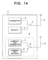
- Fig. 14 is a block diagram illustrative of the construction of a radio apparatus, such as a car phone base station.
- a radio apparatus (base station) 1 such as a car phone base station, comprises a transmitter 2, a receiver 3, an antenna change-over switch 4 for switching between transmitting and receiving modes, a transmitting/receiving antenna 5 used for normal communications, a transmitting/receiving device 6 used for loopback tests (tester), an antenna change-over switch 9 for switching between transmitting and receiving modes, and a transmitting/receiving antenna 10 used for loopback tests.
- the loopback test transmitting/receiving device further includes a loopback test transmitter 7 and a loopback test receiver 8.
- the base station 1 also comprises a controller formed of CPU, RAM, ROM, interfaces and the like, though not shown.
- radio waves transmitted from the transmitter 2 of the radio apparatus 1 are received by the loopback test receiver 8, or radio waves transmitted from the loopback test transmitter 7 are received by the receiver 3 of the radio apparatus 1, whereby it can be conventionally checked that the radio apparatus 1 properly operates.
- the radio apparatus 1 comprises the transmitter 2, the receiver 3, and the loopback test transmitting/receiving device 6 which is formed of the loopback test transmitter 7 and receiver 8.
- the radio apparatus 1 For performing a loopback test, a signal from the transmitter 2 is transmitted through the transmitting/receiving antenna 5 used for normal communications and is received by the loopback test receiver 8 through the loopback test transmitting/receiving antenna 10. If this receiving operation is correctly accomplished, it can be checked that the transmitter 2 and the antenna 5 properly operate.
- a signal from the loopback test transmitter 7 is transmitted through the loopback test transmitting/receiving antenna 10 and is received by the receiver 3 through the antenna 5 used for normal communications. If this receiving operation is correctly accomplished, it can be checked that the antenna 5 and the receiver 3 properly operate.
- the above-described conventional radio apparatus 1 has a problem in that the transmitting/receiving device (tester) 6 specifically used for loopback tests should be arranged within the apparatus 1.
- the apparatus 1 also presents the following problem.
- the loopback test indicates poor results, it is difficult to identify which element is faulty, i.e., the transmitter 2, the receiver 3, or the loopback test transmitting/receiving device (tester) 6.
- an object of the present invention is to provide a radio apparatus which is able to perform a loopback test without requiring a transmitting and receiving device (tester) specifically used for a loopback test.
- a radio apparatus comprising: a transmitter for transmitting loopback test data during an unassigned transmitting slot which is not occupied for communicating with a mobile station; an attenuator for attenuating the loopback test data transmitted from the transmitter; a receiver for receiving the loopback test data attenuated by the attenuator during the transmitting slot; a memory for storing the loopback test data received by the receiver; and a controller including a transmitting signal processing section and a receiving signal processing section, the transmitting signal processing section generating the loopback test data and transmitting it to the transmitter, the receiving signal processing section comparing the loopback test data read from the memory during an unassigned receiving slot which is not occupied for communicating with the mobile station with the loopback test data generated in the transmitting signal processing section, and upon such a comparison, issuing an alarm when an abnormality has occurred.
- a radio apparatus comprising: a transmitter for transmitting communication data during a transmitting slot which is occupied for communicating with a mobile station; an attenuator for attenuating the communication data transmitted from the transmitter; a receiver for receiving the communication data attenuated by the attenuator during the transmitting slot; a memory for storing the communication data received by the receiver; and a controller including a transmitting signal processing section and a receiving signal processing section, the transmitting signal processing section generating the communication data and transmitting it to the transmitter, the receiving signal processing section comparing the communication data read from the memory during an unassigned receiving slot which is not occupied for communicating with the mobile station with the communication data generated in the transmitting signal processing section, and upon such a comparison, issuing an alarm when an abnormality has occurred.
- a radio apparatus comprising: a receiver for receiving loopback test data through a transmitting/receiving antenna during a receiving slot which is occupied for communicating with a mobile station; a memory for storing the loopback test data received by the receiver during the receiving slot; a controller including a transmitting signal processing section, and a receiving signal processing section reading the loopback test data from the memory during a transmitting slot which is occupied for communicating with the mobile station so as to transmit the data to the transmitter; and a transmitter for transmitting the read loopback test data through the antenna during the transmitting slot.
- a radio apparatus comprising: a receiver receiving first loopback test data through a transmitting/receiving antenna during a first receiving slot occupied for communicating with a first mobile station and also receiving second loopback test data through the antenna during a second receiving slot occupied for communicating with a second mobile station; a first memory for storing the first loopback test data received by the receiver during the first receiving slot; a second memory for storing the second loopback test data received by the receiver during the second receiving slot; a controller including a transmitting signal processing section, and a receiving signal processing section reading the first loopback test data from the first memory and transmitting it to the transmitter during a second transmitting slot occupied for communicating with the second mobile station, said receiving signal processing section also reading the second loopback test data from the second memory and transmitting it to the transmitter during a first transmitting slot occupied for communicating with the first mobile station; and a transmitter transmitting the read first loopback test data through the antenna during
- Fig. 1 illustrates the construction of the first embodiment of the present invention.
- the same reference numerals in the respective figures designate the same or corresponding components.
- a radio apparatus 1A having a loopback test function comprises a transmitter 2, a receiver 3, an antenna change-over switch 4, a transmitting/receiving antenna 5, a change-over switch 12, an attenuator 13, a memory 14 for temporarily storing output signal data from the receiver 3, a change-over switch 15 for selecting between a signal output from the receiver 3 and a signal read from the memory 14, and a controller 40.
- the controller 40 includes CPU, ROM, RAM, interfaces and the like functioning as hardware.
- the controller 40 also has a transmitting signal processing section 11 primarily for generating transmitting signals and a receiving signal processing section 16 largely for producing receiving signals.
- Fig. 2 illustrates a mobile communication system using the first embodiment of the present invention.
- Fig. 3 is a time slot according to a TDMA/TDD method of the mobile communication system shown in Fig. 2.
- Fig. 4 is a flow chart illustrative of the operation of the controller 40 according to the first embodiment.
- Fig. 2 shows a radio apparatus (a car phone base station) 1A having a loopback test function and also illustrates one mobile station 20, such as a car phone or the like, having communications with the radio apparatus 1A.
- Reference numeral 21 indicates a radio communication path between the base station 1A and the mobile station 20.
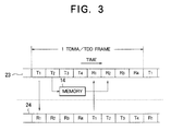
- Fig. 3 illustrates the communication between the base station 1A and the mobile station 20 and also shows a loopback test performed therebetween, the horizonal axis designating a time axis.
- Fig. 3 indicates a time slot of a mobile communication system according to a qaudruplex TDMA/TDD method by way of example. This system enables one base station to communicate with a maximum of four mobile stations. 23 designates a time slot of the base station 1A, while 24 represents a time slot of the mobile station 20.
- the time slot 23 for one frame of the base station 1A is constructed of transmitting slot segments T1, T2, T3, T4 and receiving slot segments R1, R2, R3, R4.
- a duration of 5ms is allocated to one frame of the TDMA/TDD system, and a duration of 625 ⁇ s is allocated to each slot segment.
- Information for a data length of 5ms is transmitted as burst signals to the respective four mobile stations from the base station 1A at 625 ⁇ s, at the timing shown in Fig. 3.
- Each mobile station compresses its own transmitting information into a data length of 625 ⁇ s after 2.5ms since it receives a signal from the base station 1A so as to perform burst transmission.
- Fig. 3 illustrates a communication performed between the base station 1A and the mobile station 20 shown in Fig.2 by use of a first slot (slot segments T1 and R1).
- the base station 1A transmits information using the transmitting slot segment T1 of the time slot 23
- the mobile station 20 receives such information using the receiving slot segment R1 of the time slot 24.
- the base station 1A receives such information in the receiving slot R1 of the time slot 23.
- the attenuator 13, and the change-over switch 12 connected to a path to the attenuator 13 are disposed to prevent radio waves used for a loopback test from radiating from the transmitting/receiving antenna 5.
- This attenuator 13 is also disposed for decreasing power which should be increased when transmitting signals are radiated as radio waves.
- a loopback test signal such as a press button dialing (DTMF: dual tone multi-frequency) signal or the like
- T2 is determined to be an unassigned slot, in this case.
- the controller 40 first changes the antenna change-over switch 4 to the side of the receiver 3 and connects (ON) the change-over switch 12 (step 51) through the receiving signal processing section 16.
- the controller 40 transmits through the transmitter 2 a loopback test signal (step 52), which then passes through the change-over switch 12 and the attenuator 13 so as to be input into the receiver 3.
- the received data (loopback test signal) is then stored in the memory 14 (step 53). While normal communications other than the loopback test are performed, the antenna change-over switch 4 is connected to the side of the transmitter 2 in the transmitting slot segment T1, while it is connected to the side of the receiver 3 in the receiving slot segment R1. Also, the change-over switch 12 is disconnected (OFF), and the change-over switch 15 is connected to the side of the receiver 3.
- step 54 It is again determined whether an unassigned slot is available, in this case, the receiving slot segment R2 (step 54). Then, the change-over switch 15 is changed to the side of the memory 14 (step 55), and the stored received test data is read from the memory 14 (step 56). The receiving signal processing section 16 compares the received test data with the test data generated in the transmitting signal processing section 11 (step 57). The loopback test has thus been performed according to the above-described process. If the above-mentioned two items of data do not coincide with each other, the controller 40 therefore determines that an abnormality has occurred and issues an alarm to an host exchanger (step 58).
- This embodiment takes advantages of the characteristics of the TDMA/TDD system so that a signal transmitted from its own transmitter 2 is received by its own receiver 3 within the base station 1A during an unassigned slot period, thereby realizing a loopback test. Since the base station 1A performs a loopback test by use of its own transmitter 2 and receiver 3, a tester (transmitter and receiver) specifically used for a loopback test is not required, which further eliminates the necessity of considering a possible breakdown of the loopback test transmitter and receiver. The first embodiment also offers the advantage of performing a loopback test while normal communications are being made. Further, since the base station utilizes its own transmitter and receiver, there can be an improvement in the reliability of the loopback test.
- the first embodiment has been explained in which a loopback test is performed during the second slot (T2, R2). However, since only one mobile station in the first slot is communicating with the base station 1A, a loopback test may also be performed in the third slot (T3, R3) or the fourth slot (T4, R4). When all the four mobile stations are having normal communications with the base station 1A, no unassigned slot is available, and accordingly, it is impossible to perform a loopback test.
- Advantages similar to those obtained in the first embodiment are not limited to a quadruplex system, but may be obtained in duplex, triplex, fivefold, sixfold, sevenfold, eightfold, ninefold, tenfold and twentyfold systems. In short, any multiplex system may be employed as long as at least one unassigned (not in use) slot is available.
- an unassigned slot is employed to transmit a loopback test signal and to receive it, thereby realizing a loopback test.
- a signal used in a transmitting slot segment which is occupied for communicating with the mobile station is simultaneously received by its own receiver, thus performing a loopback test.
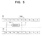
- a base station of the second embodiment is constructed in a manner similar to the first embodiment shown in Fig. 1, except for the operation timing illustrated in Figs. 5 and 6.
- Fig. 5 illustrates a time slot of a mobile communication system according to the second embodiment of the present invention.
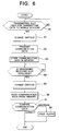
- Fig. 6 is a flow chart illustrative of the operation of the controller 40 according to the second embodiment.
- the controller 40 changes the antenna change-over switch 4 to the side of the transmitter 2 and connects (ON) the change-over switch 12 through the receiving signal processing section 16 (step 61). Subsequently, the controller 40 actuates the transmitter 2 and simultaneously operates the receiver 3 and then writes a signal which is usually employed for normal communications (communication data) into the memory 14 (steps 62 and 63).
- the controller 40 changes the change-over switch 15 to the side of the memory 14 (step 65) so as to read the received communication data from the memory 14 (step 66).
- the controller 40 compares the received communication data with communication data stored in the transmitting signal processing section 11 (step 67).
- the loopback test has thus been performed according to the above-described process. If the above-mentioned two items of data do not coincide with each other, the controller 40 determines that an abnormality has occurred and issues an alarm to a host exchanger (step 68). Hence, it is not necessary to generate loopback test transmitting data (test data) by the transmitting signal processing section 11.
- the other advantages are similar to those obtained in the first embodiment.
- FIG. 7A illustrates the construction of a base station according to the third embodiment of the present invention.
- Fig. 7B illustrates the construction of a mobile station according to the third embodiment.
- Fig. 8 illustrates a time slot of a mobile communication system according to this embodiment.
- Fig. 9 is a flow chart illustrative of the operation of the controller 40 of the base station according to this embodiment.
- a radio apparatus (base station) 1B comprises a transmitter 2, a receiver 3, an antenna change-over switch 4, a transmitting/receiving antenna 5, a memory 14 for temporarily storing output signal data from the receiver 3, a change-over switch 17 for selecting between a signal read from the memory 14 and a transmitting signal from a transmitting signal processing section 11, and a controller 40.
- a radio apparatus (mobile station) 20 comprises a transmitting/receiving antenna 22, an antenna change-over switch 26, a transmitter 27, a receiver 28, and a controller 29 formed of CPU, ROM, RAM, interfaces and the like.
- a signal received from the mobile station 20 can be looped within the base station 1B so as to be transmitted back to the mobile station 20, thus carrying out a loopback test of the mobile station 20 through use of the base station 1B.
- the base station 1B of this embodiment has the memory 14 for storing communication data (test data) received from the mobile station 20.
- the controller 40 changes the antenna change-over switch 4 to the side of the receiver 3 through the receiving signal processing section (step 71).
- the controller 40 then receives radio waves from the mobile station 20 (step 72), and writes the test data into the memory 14 (step 73).
- the controller 40 changes the change-over switch 17 to the side of the memory 14 (step 75) so as to read the test data from the memory 14(step 76) and to directly transmit the data to the mobile station 20 (step 77).
- This process enables the mobile station 20 to perform a loopback test without requiring a memory.
- a loopback test it is required that the mobile station 20 notify the base station 1B that the apparatus will go into the mobile test mode before it transmits the test data to the base station 1B.
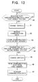
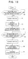
- Figs. 10, 11, 12 and 13 are flow charts illustrative of the operation of a controller according to this embodiment.
- a radio apparatus (base station) 1C comprises a transmitter 2, a receiver 3, an antenna change-over switch 4, a transmitting/receiving antenna 5, memories 14A and 14B for temporarily storing output signal data from the receiver 3, a change-over switch 18, a change-over switch 19 for selecting between a signal read from the memory 14A or 14B and a transmitting signal from the transmitting signal processing section 11, and a controller 40.
- reference numeral 30 designates a mobile station constructed in a manner similar to the mobile station 20. 25 indicates a time slot of the mobile station 30.
- the base station 1C of this embodiment having two memories 14A and 14B When the base station 1C of this embodiment having two memories 14A and 14B is operated according to a time slot shown in Fig. 11, it can function as a relay station. With this arrangement, the mobile stations 20 and 30 are able to communicate with each other via the base station 1C. One mobile station is able to perform a loopback test through use of the base station 1C and the other mobile station.
- the base station 1C receives radio waves from two mobile stations 20 and 30 so as to write signals into the memories 14A and 14B, respectively. Then, it reads one of the signals transmitted from one mobile station and transmits it to the other station at the timing of a transmitting slot segment, thus relaying between the base stations 20 and 30.
- a first receiving slot segment R1 used for receiving data from the mobile station 20 the controller 40 of the base station 1C changes the antenna change-over switch 4 and the change-over switch 18 (step 81).
- the controller 40 thus receives communication A from the mobile station 20 (step 82) and writes it into the memory 14A (step 83).
- a second transmitting slot segment T2 used for transmitting data to the mobile station 30 the controller 40 changes the change-over switch 19 and the antenna change-over switch 4 (step 85).
- the controller 40 thus reads communication B from the memory 14A (step 86) so as to transmit it to the mobile station 30 (step 87).
- a second receiving slot segment R2 used for receiving data from the mobile station 30 the controller 40 of the base station 1C changes the antenna change-over switch 4 and the change-over switch 18 (step 91).
- the controller 40 thus receives communication C from the mobile station 30 (step 92) and writes it into the memory 14B (step 93).
- the controller 40 changes the changeover switch 19 and the antenna change-over switch 4 (step 95).
- the controller 40 thus reads communication D from the memory 14B (step 96) and transmits it to the mobile station 20 (step 97).
- the mobile station 20 is able to communicate with the other mobile station 30 using its own slot, i.e, the first slot, thus carrying out a loopback test.
- the mobile station 30 is able to communicate with the mobile station 20 using its own slot, i.e., the second slot, thus performing a loopback test.
- This enables both the mobile stations 20 and 30 to each perform a loopback test without requiring a memory.
- a loopback test it is required that the mobile stations 20 and 30 notify the base station 1C that the apparatus will go into the mobile test mode before they transmit the test data to the base station 1C.
Abstract
Description
- The present invention relates to a radio apparatus, for example, a car phone base station, which performs radio communications with a plurality of mobile stations (car phones, transportable phones and the like) according to a TDMA (Time Division Multiple Access)/TDD (Time Division Duplex) system. This TDMA/TDD system is employed whereby transmitting information and receiving information can be alternately transmitted and received to effect multiplex transmission by use of respective channels of a plurality of radio carriers allocated to digital cordless phones.
- The construction of a typical conventional radio apparatus will now be explained with reference to Fig. 14. Fig. 14 is a block diagram illustrative of the construction of a radio apparatus, such as a car phone base station.
- Referring to Fig. 14, a radio apparatus (base station) 1, such as a car phone base station, comprises a
transmitter 2, areceiver 3, an antenna change-overswitch 4 for switching between transmitting and receiving modes, a transmitting/receivingantenna 5 used for normal communications, a transmitting/receivingdevice 6 used for loopback tests (tester), an antenna change-overswitch 9 for switching between transmitting and receiving modes, and a transmitting/receivingantenna 10 used for loopback tests. The loopback test transmitting/receiving device further includes a loopback test transmitter 7 and aloopback test receiver 8. Thebase station 1 also comprises a controller formed of CPU, RAM, ROM, interfaces and the like, though not shown. - A description will now be given of the operation of the conventional radio apparatus constructed as described above. As shown in Fig. 14, radio waves transmitted from the
transmitter 2 of theradio apparatus 1 are received by theloopback test receiver 8, or radio waves transmitted from the loopback test transmitter 7 are received by thereceiver 3 of theradio apparatus 1, whereby it can be conventionally checked that theradio apparatus 1 properly operates. - That is, the
radio apparatus 1 comprises thetransmitter 2, thereceiver 3, and the loopback test transmitting/receivingdevice 6 which is formed of the loopback test transmitter 7 andreceiver 8. For performing a loopback test, a signal from thetransmitter 2 is transmitted through the transmitting/receivingantenna 5 used for normal communications and is received by theloopback test receiver 8 through the loopback test transmitting/receivingantenna 10. If this receiving operation is correctly accomplished, it can be checked that thetransmitter 2 and theantenna 5 properly operate. - On the other hand, a signal from the loopback test transmitter 7 is transmitted through the loopback test transmitting/receiving
antenna 10 and is received by thereceiver 3 through theantenna 5 used for normal communications. If this receiving operation is correctly accomplished, it can be checked that theantenna 5 and thereceiver 3 properly operate. - However, the above-described
conventional radio apparatus 1 has a problem in that the transmitting/receiving device (tester) 6 specifically used for loopback tests should be arranged within theapparatus 1. - The
apparatus 1 also presents the following problem. When the loopback test indicates poor results, it is difficult to identify which element is faulty, i.e., thetransmitter 2, thereceiver 3, or the loopback test transmitting/receiving device (tester) 6. - Accordingly, in order to solve the above problems, an object of the present invention is to provide a radio apparatus which is able to perform a loopback test without requiring a transmitting and receiving device (tester) specifically used for a loopback test.
- In order to achieve the above objects, according to a first aspect of the present invention, there is provided a radio apparatus according to a TDMA/TDD system, comprising: a transmitter for transmitting loopback test data during an unassigned transmitting slot which is not occupied for communicating with a mobile station; an attenuator for attenuating the loopback test data transmitted from the transmitter; a receiver for receiving the loopback test data attenuated by the attenuator during the transmitting slot; a memory for storing the loopback test data received by the receiver; and a controller including a transmitting signal processing section and a receiving signal processing section, the transmitting signal processing section generating the loopback test data and transmitting it to the transmitter, the receiving signal processing section comparing the loopback test data read from the memory during an unassigned receiving slot which is not occupied for communicating with the mobile station with the loopback test data generated in the transmitting signal processing section, and upon such a comparison, issuing an alarm when an abnormality has occurred.
- According to a second aspect of the present invention, there is provided a radio apparatus according to a TDMA/TDD system, comprising: a transmitter for transmitting communication data during a transmitting slot which is occupied for communicating with a mobile station; an attenuator for attenuating the communication data transmitted from the transmitter; a receiver for receiving the communication data attenuated by the attenuator during the transmitting slot; a memory for storing the communication data received by the receiver; and a controller including a transmitting signal processing section and a receiving signal processing section, the transmitting signal processing section generating the communication data and transmitting it to the transmitter, the receiving signal processing section comparing the communication data read from the memory during an unassigned receiving slot which is not occupied for communicating with the mobile station with the communication data generated in the transmitting signal processing section, and upon such a comparison, issuing an alarm when an abnormality has occurred.
- According to a third aspect of the present invention, there is provided a radio apparatus according to a TDMA/TDD system, comprising: a receiver for receiving loopback test data through a transmitting/receiving antenna during a receiving slot which is occupied for communicating with a mobile station; a memory for storing the loopback test data received by the receiver during the receiving slot; a controller including a transmitting signal processing section, and a receiving signal processing section reading the loopback test data from the memory during a transmitting slot which is occupied for communicating with the mobile station so as to transmit the data to the transmitter; and a transmitter for transmitting the read loopback test data through the antenna during the transmitting slot.
- According to a fourth aspect of the present invention, there is provided a radio apparatus according to a TDMA/TDD system, comprising: a receiver receiving first loopback test data through a transmitting/receiving antenna during a first receiving slot occupied for communicating with a first mobile station and also receiving second loopback test data through the antenna during a second receiving slot occupied for communicating with a second mobile station; a first memory for storing the first loopback test data received by the receiver during the first receiving slot; a second memory for storing the second loopback test data received by the receiver during the second receiving slot; a controller including a transmitting signal processing section, and a receiving signal processing section reading the first loopback test data from the first memory and transmitting it to the transmitter during a second transmitting slot occupied for communicating with the second mobile station, said receiving signal processing section also reading the second loopback test data from the second memory and transmitting it to the transmitter during a first transmitting slot occupied for communicating with the first mobile station; and a transmitter transmitting the read first loopback test data through the antenna during the second transmitting slot and also transmitting the read second loopback test data through the antenna during the first transmitting slot.
-
- Fig. 1 illustrates a radio apparatus (base station) according to a first embodiment of the present invention;
- Fig. 2 illustrates a mobile communication system by use of the radio apparatus (base station) according to the first embodiment;
- Fig. 3 illustrates a time slot of the mobile communication system according to the first embodiment;
- Fig. 4 is a flow chart illustrative of the operation of the base station shown in Fig. 1 during a test mode;
- Fig. 5 illustrates a time slot of a mobile communication system according to a second embodiment of the present invention;
- Fig. 6 is a flow chart illustrative of the base station of the second embodiment during the test mode;
- Fig. 7A illustrates a radio apparatus (base station) according to a third embodiment of the present invention;
- Fig. 7B illustrates a radio apparatus (mobile station) according to the third embodiment;
- Fig. 8 illustrates a time slot of the mobile communication system according to the third embodiment;
- Fig. 9 is a flow chart illustrative of the operation of the base station shown in Fig. 7A during the test mode;
- Fig. 10 illustrates a radio apparatus (base station) according to a fourth embodiment of the present invention;
- Fig. 11 illustrates a time slot of the mobile communication system according to the fourth embodiment;
- Fig. 12 is a flow chart illustrative of the operation of the base station shown in Fig. 10 during the test mode;
- Fig. 13 is a flow chart illustrative of the operation of the base station shown in Fig. 10 during the test mode; and
- Fig. 14 is a block diagram illustrative of the construction of a conventional radio apparatus.
- A description will now be given of the construction of a first embodiment of the present invention with reference to Fig. 1. Fig. 1 illustrates the construction of the first embodiment of the present invention. The same reference numerals in the respective figures designate the same or corresponding components.
- Referring to Fig. 1, a
radio apparatus 1A having a loopback test function comprises atransmitter 2, areceiver 3, an antenna change-overswitch 4, a transmitting/receivingantenna 5, a change-over switch 12, anattenuator 13, amemory 14 for temporarily storing output signal data from thereceiver 3, a change-overswitch 15 for selecting between a signal output from thereceiver 3 and a signal read from thememory 14, and acontroller 40. - The
controller 40 includes CPU, ROM, RAM, interfaces and the like functioning as hardware. - The
controller 40 also has a transmittingsignal processing section 11 primarily for generating transmitting signals and a receivingsignal processing section 16 largely for producing receiving signals. - The operation of the first embodiment will now be explained with reference to Figs. 2, 3 and 4. Fig. 2 illustrates a mobile communication system using the first embodiment of the present invention. Fig. 3 is a time slot according to a TDMA/TDD method of the mobile communication system shown in Fig. 2. Fig. 4 is a flow chart illustrative of the operation of the
controller 40 according to the first embodiment. - Fig. 2 shows a radio apparatus (a car phone base station) 1A having a loopback test function and also illustrates one
mobile station 20, such as a car phone or the like, having communications with theradio apparatus 1A.Reference numeral 21 indicates a radio communication path between thebase station 1A and themobile station 20. - Fig. 3 illustrates the communication between the
base station 1A and themobile station 20 and also shows a loopback test performed therebetween, the horizonal axis designating a time axis. Fig. 3 indicates a time slot of a mobile communication system according to a qaudruplex TDMA/TDD method by way of example. This system enables one base station to communicate with a maximum of four mobile stations. 23 designates a time slot of thebase station 1A, while 24 represents a time slot of themobile station 20. - Since the quadruplex TDMA/TDD system is employed, the
time slot 23 for one frame of thebase station 1A is constructed of transmitting slot segments T1, T2, T3, T4 and receiving slot segments R1, R2, R3, R4. For example, it will now be assumed that a duration of 5ms is allocated to one frame of the TDMA/TDD system, and a duration of 625µs is allocated to each slot segment. Information for a data length of 5ms is transmitted as burst signals to the respective four mobile stations from thebase station 1A at 625µs, at the timing shown in Fig. 3. Each mobile station compresses its own transmitting information into a data length of 625µs after 2.5ms since it receives a signal from thebase station 1A so as to perform burst transmission. Fig. 3 illustrates a communication performed between thebase station 1A and themobile station 20 shown in Fig.2 by use of a first slot (slot segments T1 and R1). When thebase station 1A transmits information using the transmitting slot segment T1 of thetime slot 23, themobile station 20 receives such information using the receiving slot segment R1 of thetime slot 24. On the other hand, when themobile station 20 transmits information in the transmitting slot T1 of thetime slot 24, thebase station 1A receives such information in the receiving slot R1 of thetime slot 23. - An explanation will now be given of the operation of a loopback test performed within the
base station 1A by use of a second slot (slot segments T2 and R2). While thebase station 1A is communicating with themobile station 20 using the first slot, thetransmitter 2 and thereceiver 3 within thebase station 1A are not used to communicate with themobile station 20 during periods of second, third and fourth slots. Based on this fact, thetransmitter 2 and thereceiver 3 are actuated to perform a loopback test during a period of the second slot. - However, since normal communications are performed between the
base station 1A and themobile station 20 in the first slot, the construction of thetime slot 23 cannot be altered. Thus, a signal transmitted from thetransmitter 2 in the second slot is received by thereceiver 3 so as to be temporarily stored in thememory 14. The signal which has been stored during the receiving slot segment R2 is read from thememory 14 so as to be output to the receivingsignal processing section 16, thus realizing a loopback test. - The
attenuator 13, and the change-over switch 12 connected to a path to theattenuator 13 are disposed to prevent radio waves used for a loopback test from radiating from the transmitting/receivingantenna 5. Thisattenuator 13 is also disposed for decreasing power which should be increased when transmitting signals are radiated as radio waves. - The operation of the
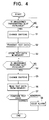
controller 40 to perform a loopback test will now be explained with reference to Fig. 4. It is first determined whether an unassigned slot is available for transmitting a loopback test signal (test data), such as a press button dialing (DTMF: dual tone multi-frequency) signal or the like, generated in the transmittingsignal processing section 11 within the controller 40 (step 50). For example, T2 is determined to be an unassigned slot, in this case. With this preparation, thecontroller 40 first changes the antenna change-overswitch 4 to the side of thereceiver 3 and connects (ON) the change-over switch 12 (step 51) through the receivingsignal processing section 16. - Then, the
controller 40 transmits through the transmitter 2 a loopback test signal (step 52), which then passes through the change-over switch 12 and theattenuator 13 so as to be input into thereceiver 3. The received data (loopback test signal) is then stored in the memory 14 (step 53). While normal communications other than the loopback test are performed, the antenna change-overswitch 4 is connected to the side of thetransmitter 2 in the transmitting slot segment T1, while it is connected to the side of thereceiver 3 in the receiving slot segment R1. Also, the change-over switch 12 is disconnected (OFF), and the change-over switch 15 is connected to the side of thereceiver 3. - It is again determined whether an unassigned slot is available, in this case, the receiving slot segment R2 (step 54). Then, the change-
over switch 15 is changed to the side of the memory 14 (step 55), and the stored received test data is read from the memory 14 (step 56). The receivingsignal processing section 16 compares the received test data with the test data generated in the transmitting signal processing section 11 (step 57). The loopback test has thus been performed according to the above-described process. If the above-mentioned two items of data do not coincide with each other, thecontroller 40 therefore determines that an abnormality has occurred and issues an alarm to an host exchanger (step 58). - This embodiment takes advantages of the characteristics of the TDMA/TDD system so that a signal transmitted from its
own transmitter 2 is received by itsown receiver 3 within thebase station 1A during an unassigned slot period, thereby realizing a loopback test. Since thebase station 1A performs a loopback test by use of itsown transmitter 2 andreceiver 3, a tester (transmitter and receiver) specifically used for a loopback test is not required, which further eliminates the necessity of considering a possible breakdown of the loopback test transmitter and receiver. The first embodiment also offers the advantage of performing a loopback test while normal communications are being made. Further, since the base station utilizes its own transmitter and receiver, there can be an improvement in the reliability of the loopback test. - The first embodiment has been explained in which a loopback test is performed during the second slot (T2, R2). However, since only one mobile station in the first slot is communicating with the
base station 1A, a loopback test may also be performed in the third slot (T3, R3) or the fourth slot (T4, R4). When all the four mobile stations are having normal communications with thebase station 1A, no unassigned slot is available, and accordingly, it is impossible to perform a loopback test. Advantages similar to those obtained in the first embodiment are not limited to a quadruplex system, but may be obtained in duplex, triplex, fivefold, sixfold, sevenfold, eightfold, ninefold, tenfold and twentyfold systems. In short, any multiplex system may be employed as long as at least one unassigned (not in use) slot is available. - In the above-described first embodiment, an unassigned slot is employed to transmit a loopback test signal and to receive it, thereby realizing a loopback test. In a second embodiment, a signal used in a transmitting slot segment which is occupied for communicating with the mobile station is simultaneously received by its own receiver, thus performing a loopback test.
- A base station of the second embodiment is constructed in a manner similar to the first embodiment shown in Fig. 1, except for the operation timing illustrated in Figs. 5 and 6. Fig. 5 illustrates a time slot of a mobile communication system according to the second embodiment of the present invention. Fig. 6 is a flow chart illustrative of the operation of the
controller 40 according to the second embodiment. - An explanation will now be given of the operation of the
controller 40 to perform a loopback test according to this embodiment with reference to Fig. 6. In the first slot during which normal communications are being made, that is, during the transmitting slot segment T1 of thetime slot 23 of thebase station 1A (step 60), thecontroller 40 changes the antenna change-overswitch 4 to the side of thetransmitter 2 and connects (ON) the change-over switch 12 through the receiving signal processing section 16 (step 61). Subsequently, thecontroller 40 actuates thetransmitter 2 and simultaneously operates thereceiver 3 and then writes a signal which is usually employed for normal communications (communication data) into the memory 14 (steps 62 and 63). - During the period of the receiving slot segment R2, which is unassigned, of the time slot 23 (step 64), the
controller 40 changes the change-over switch 15 to the side of the memory 14 (step 65) so as to read the received communication data from the memory 14 (step 66). Thecontroller 40 then compares the received communication data with communication data stored in the transmitting signal processing section 11 (step 67). The loopback test has thus been performed according to the above-described process. If the above-mentioned two items of data do not coincide with each other, thecontroller 40 determines that an abnormality has occurred and issues an alarm to a host exchanger (step 68). Hence, it is not necessary to generate loopback test transmitting data (test data) by the transmittingsignal processing section 11. The other advantages are similar to those obtained in the first embodiment. - A third embodiment of the present invention will now be described with reference to Figs. 7A, 7B, 8 and 9. Fig. 7A illustrates the construction of a base station according to the third embodiment of the present invention. Fig. 7B illustrates the construction of a mobile station according to the third embodiment. Fig. 8 illustrates a time slot of a mobile communication system according to this embodiment. Fig. 9 is a flow chart illustrative of the operation of the
controller 40 of the base station according to this embodiment. - Referring to Fig. 7A, a radio apparatus (base station) 1B comprises a
transmitter 2, areceiver 3, an antenna change-overswitch 4, a transmitting/receivingantenna 5, amemory 14 for temporarily storing output signal data from thereceiver 3, a change-over switch 17 for selecting between a signal read from thememory 14 and a transmitting signal from a transmittingsignal processing section 11, and acontroller 40. - Referring to Fig. 7B, a radio apparatus (mobile station) 20 comprises a transmitting/receiving
antenna 22, an antenna change-over switch 26, atransmitter 27, areceiver 28, and acontroller 29 formed of CPU, ROM, RAM, interfaces and the like. - With this construction shown in Fig. 7A, a signal received from the
mobile station 20 can be looped within thebase station 1B so as to be transmitted back to themobile station 20, thus carrying out a loopback test of themobile station 20 through use of thebase station 1B. - That is, the
base station 1B of this embodiment has thememory 14 for storing communication data (test data) received from themobile station 20. In the mobile station test mode, in a receiving slot segment R1 used for receiving a signal from the mobile station 20 (step 70), thecontroller 40 changes the antenna change-overswitch 4 to the side of thereceiver 3 through the receiving signal processing section (step 71). Thecontroller 40 then receives radio waves from the mobile station 20 (step 72), and writes the test data into the memory 14 (step 73). - Subsequently, at the timing of the transmitting slot segment T1 during which data is transmitted to the mobile station 20 (step 74), the
controller 40 changes the change-over switch 17 to the side of the memory 14 (step 75) so as to read the test data from the memory 14(step 76) and to directly transmit the data to the mobile station 20 (step 77). This process enables themobile station 20 to perform a loopback test without requiring a memory. When a loopback test is performed, it is required that themobile station 20 notify thebase station 1B that the apparatus will go into the mobile test mode before it transmits the test data to thebase station 1B. - Further, a fourth embodiment of the present invention will be explained with reference to Figs. 10, 11, 12 and 13. Fig. 10 illustrates the construction of the fourth embodiment of the present invention. Fig. 11 illustrates a time slot of a mobile communication system according to the fourth embodiment. Figs. 12 and 13 are flow charts illustrative of the operation of a controller according to this embodiment.
- Referring to Fig. 10, a radio apparatus (base station) 1C comprises a
transmitter 2, areceiver 3, an antenna change-overswitch 4, a transmitting/receivingantenna 5,memories receiver 3, a change-over switch 18, a change-over switch 19 for selecting between a signal read from thememory signal processing section 11, and acontroller 40. - Referring to Fig. 11,
reference numeral 30 designates a mobile station constructed in a manner similar to themobile station 20. 25 indicates a time slot of themobile station 30. - When the
base station 1C of this embodiment having twomemories mobile stations base station 1C. One mobile station is able to perform a loopback test through use of thebase station 1C and the other mobile station. - The
base station 1C receives radio waves from twomobile stations memories base stations - An explanation will now be given of the operation of the
controller 40 to perform a loopback test with reference to Figs. 12 and 13. - In a first receiving slot segment R1 used for receiving data from the mobile station 20 (step 80), the
controller 40 of thebase station 1C changes the antenna change-overswitch 4 and the change-over switch 18 (step 81). Thecontroller 40 thus receives communication A from the mobile station 20 (step 82) and writes it into thememory 14A (step 83). Subsequently, in a second transmitting slot segment T2 used for transmitting data to the mobile station 30 (step 84), thecontroller 40 changes the change-over switch 19 and the antenna change-over switch 4 (step 85). Thecontroller 40 thus reads communication B from thememory 14A (step 86) so as to transmit it to the mobile station 30 (step 87). - Further, in a second receiving slot segment R2 used for receiving data from the mobile station 30 (step 90), the
controller 40 of thebase station 1C changes the antenna change-overswitch 4 and the change-over switch 18 (step 91). Thecontroller 40 thus receives communication C from the mobile station 30 (step 92) and writes it into thememory 14B (step 93). Subsequently, in a first transmitting slot segment T1 used for transmitting data to the mobile station 20 (step 94), thecontroller 40 changes thechangeover switch 19 and the antenna change-over switch 4 (step 95). Thecontroller 40 thus reads communication D from thememory 14B (step 96) and transmits it to the mobile station 20 (step 97). - According to the above-described process, the
mobile station 20 is able to communicate with the othermobile station 30 using its own slot, i.e, the first slot, thus carrying out a loopback test. The same applies to themobile station 30. That is, themobile station 30 is able to communicate with themobile station 20 using its own slot, i.e., the second slot, thus performing a loopback test. This enables both themobile stations mobile stations base station 1C that the apparatus will go into the mobile test mode before they transmit the test data to thebase station 1C.
Claims (10)
- A radio apparatus according to a TDMA/TDD system, comprising:- a transmitter (2) for transmitting data during a transmitting slot;- an attenuator (13) for attenuating the data transmitted from the transmitter (2);- a receiver (3) for receiving the data attenuated by the attenuator (13) during the transmitting slot;- a memory (14) for storing the data received by the receiver (3); and- a controller (11, 16, 40) for comparing the data read from the memory (14) with the data transmitted from the transmitter (2) so as to assess normality of the apparatus during an unassigned receiving slot.
- A radio apparatus according to claim 1,
wherein the transmitting slot is unassigned, and the data is used for a loopback test. - A radio apparatus according to claim 1 or 2,
wherein the controller (40) comprises a transmitting signal processing section (11) and a receiving signal processing section (16), the transmitting signal processing section (11) generating the loopback test data and transmitting it to the transmitter (2), the receiving signal processing section (16) comparing the loopback test data read from the memory (14) with the loopback test data generated in the transmitting signal processing section (11), and upon such a comparison, issuing an alarm when an abnormality has occurred. - A radio apparatus according to any of claims 1 to 3, wherein- the transmitting slot is occupied for communicating with a mobile station (20), and- the data is communication data used for communicating with the mobile station (20).
- A radio apparatus according to any of claims 1 to 4,
wherein the controller (40) comprises a transmitting signal processing section (11) and a receiving signal processing section (16), the transmitting signal processing section (11) generating the communication data and transmitting it to the transmitter (2), the receiving signal processing section (16) comparing the communication data read from the memory (14) with the communication data generated in the transmitting signal processing section (11), and upon such a comparison, issuing an alarm when an abnormality has occurred. - A radio apparatus according to a TDMA/TDD system, comprising:- a receiver (3) for receiving data through a transmitting/receiving antenna (5) during a receiving slot;- a memory (14) for storing the data received by the receiver (3) during the receiving slot;- a controller (40) for reading the data from the memory (14) during a transmitting slot; and- a transmitter (2) for transmitting the data read from the memory (14) during the transmitting slot through the antenna (5).
- A radio apparatus according to claim 6,
wherein the receiving slot is occupied for communicating with a mobile station (20), and the data is loopback test data used for communicating with the mobile station (20), the transmitting slot being occupied for communicating with the mobile station (20). - A radio apparatus according to claim 6 or 7,
wherein the controller (40) comprises a transmitting signal processing section (11) and a receiving signal processing section (16), and the receiving signal processing section (16) reads the loopback test data from the memory (14) and transmits it to the transmitter (2). - A radio apparatus according to any of claims 6 to 8,
wherein the receiving slot is formed of a first receiving slot segment occupied for communicating with a first mobile station (20) and a second receiving slot segment occupied for communicating with a second mobile station (30), the data being loopback test data used for communicating with the first mobile station (20) and also used for communicating with the second mobile station (30), the transmitting slot being formed of a first transmitting slot segment occupied for communicating with the first mobile station (20) and a second transmitting slot segment occupied for communicating with the second mobile station (30). - A radio apparatus according to any of claims 6 to 9,
wherein the controller (40) comprises a transmitting signal processing section (11) and a receiving signal processing section (16), the memory (14) including first (14a) and second memory portions (14b), the receiving signal processing section (16) reading the loopback test data from the first memory portion (14a) and transmitting it to the transmitter (2) and also reading the loopback test data from the second memory portion (14b) and transmitting it to the transmitter (2).
Priority Applications (1)
| Application Number | Priority Date | Filing Date | Title |
|---|---|---|---|
| EP04000339A EP1434370A3 (en) | 1994-07-01 | 1995-07-03 | Transmitter and receiver for use in TDMA/TDD mobile radio communications systems having loopback test facilities |
Applications Claiming Priority (3)
| Application Number | Priority Date | Filing Date | Title |
|---|---|---|---|
| JP06151238A JP3078177B2 (en) | 1994-07-01 | 1994-07-01 | Wireless device |
| JP151238/94 | 1994-07-01 | ||
| JP15123894 | 1994-07-01 |
Related Child Applications (1)
| Application Number | Title | Priority Date | Filing Date |
|---|---|---|---|
| EP04000339A Division EP1434370A3 (en) | 1994-07-01 | 1995-07-03 | Transmitter and receiver for use in TDMA/TDD mobile radio communications systems having loopback test facilities |
Publications (3)
| Publication Number | Publication Date |
|---|---|
| EP0690593A2 true EP0690593A2 (en) | 1996-01-03 |
| EP0690593A3 EP0690593A3 (en) | 1999-12-15 |
| EP0690593B1 EP0690593B1 (en) | 2004-05-19 |
Family
ID=15514278
Family Applications (2)
| Application Number | Title | Priority Date | Filing Date |
|---|---|---|---|
| EP04000339A Withdrawn EP1434370A3 (en) | 1994-07-01 | 1995-07-03 | Transmitter and receiver for use in TDMA/TDD mobile radio communications systems having loopback test facilities |
| EP95110354A Expired - Lifetime EP0690593B1 (en) | 1994-07-01 | 1995-07-03 | Transmitter and receiver for use in TDMA/TDD mobile radio communications systems having loopback test facilities |
Family Applications Before (1)
| Application Number | Title | Priority Date | Filing Date |
|---|---|---|---|
| EP04000339A Withdrawn EP1434370A3 (en) | 1994-07-01 | 1995-07-03 | Transmitter and receiver for use in TDMA/TDD mobile radio communications systems having loopback test facilities |
Country Status (4)
| Country | Link |
|---|---|
| US (1) | US5742589A (en) |
| EP (2) | EP1434370A3 (en) |
| JP (1) | JP3078177B2 (en) |
| DE (1) | DE69533049T2 (en) |
Cited By (16)
| Publication number | Priority date | Publication date | Assignee | Title |
|---|---|---|---|---|
| WO1997000586A1 (en) * | 1995-06-16 | 1997-01-03 | Nokia Telecommunications Oy | Method and apparatus for establishing a test loop for monitoring the operation of a radio station |
| GB2314485A (en) * | 1996-06-17 | 1997-12-24 | Nec Corp | Testing the integrity of a radio apparatus using a loop-back test method |
| DE19625588A1 (en) * | 1996-06-27 | 1998-01-02 | Deltron Elektronische Systeme | Radio remote control system operation method e.g. for garage door |
| WO1998017019A2 (en) * | 1996-10-11 | 1998-04-23 | Siemens Aktiengesellschaft | Test method for a mobile receiver |
| WO1998037652A2 (en) * | 1997-02-24 | 1998-08-27 | At & T Wireless Services, Inc. | Transmit/receive compensation for a dual fdd/tdd architecture |
| WO1998037650A3 (en) * | 1997-02-24 | 1998-10-22 | At & T Wireless Services Inc | Transmit/receive compensation in a discrete multitone spread spectrum system |
| EP0911993A2 (en) * | 1997-10-22 | 1999-04-28 | Matsushita Electric Industrial Co., Ltd. | TDMA radio terminal capable of adjusting transmit timing by using measured delay time |
| EP0920146A2 (en) * | 1997-11-26 | 1999-06-02 | Lucent Technologies Inc. | Transceiver with rf loopback and downlink frequency scanning |
| EP0961510A2 (en) * | 1998-05-26 | 1999-12-01 | Siemens Aktiengesellschaft | System for testing the operation of a base station of a radio communication system |
| EP1154580A1 (en) * | 2000-05-09 | 2001-11-14 | Alcatel | A method for controlling the transmitter part of a radio transceiver and a corresponding radio transceiver |
| CN1086078C (en) * | 1997-01-17 | 2002-06-05 | 三星电子株式会社 | Transmitter/receiver for use in multichannel time division duplexing system |
| WO2003019825A1 (en) * | 2001-08-24 | 2003-03-06 | Siemens Aktiengesellschaft | Method for improving quality of transmitted data using loopback during operation |
| US6600776B1 (en) | 1997-02-24 | 2003-07-29 | At&T Wireless Services, Inc. | Vertical adaptive antenna array for a discrete multitone spread spectrum communications system |
| US6785300B2 (en) | 1997-02-06 | 2004-08-31 | At&T Wireless Services, Inc. | Delay compensation |
| US6999440B2 (en) | 1997-10-22 | 2006-02-14 | Matsushita Electric Industrial Co., Ltd. | TDMA radio terminal capable of adjusting transmit timing by using measured delay time |
| WO2008102313A2 (en) * | 2007-02-23 | 2008-08-28 | Nxp B.V. | Testable electronic device for wireless communication |
Families Citing this family (37)
| Publication number | Priority date | Publication date | Assignee | Title |
|---|---|---|---|---|
| JP3646393B2 (en) * | 1996-02-29 | 2005-05-11 | 三菱電機株式会社 | Digital wireless phone |
| JPH09298521A (en) * | 1996-05-08 | 1997-11-18 | Nec Eng Ltd | Method and system for controlling radio communication repetition |
| US5933421A (en) | 1997-02-06 | 1999-08-03 | At&T Wireless Services Inc. | Method for frequency division duplex communications |
| US5909641A (en) * | 1997-02-24 | 1999-06-01 | At&T Wireless Services Inc. | Transmit/receive switch |
| US6584144B2 (en) | 1997-02-24 | 2003-06-24 | At&T Wireless Services, Inc. | Vertical adaptive antenna array for a discrete multitone spread spectrum communications system |
| SE512115C2 (en) * | 1997-09-08 | 2000-01-24 | Ericsson Telefon Ab L M | Test transmitter and method of manufacturing a mobile test transmitter for a mobile telecommunication system |
| US6075986A (en) * | 1997-10-06 | 2000-06-13 | Lucent Technologies Inc. | In-set evaluation procedures for components |
| US6188876B1 (en) * | 1998-01-28 | 2001-02-13 | Fine Digital, Inc. | System and method for remote monitoring of RF units in base station of wireless communication network |
| US6397042B1 (en) * | 1998-03-06 | 2002-05-28 | Texas Instruments Incorporated | Self test of an electronic device |
| US6311044B1 (en) * | 1998-04-20 | 2001-10-30 | Motorola, Inc. | Method and apparatus for determining failure modes of a transceiver |
| WO2000036492A2 (en) * | 1998-12-18 | 2000-06-22 | Triconex Corporation | Method and apparatus for processing control using a multiple redundant processor control system |
| US6738601B1 (en) * | 1999-10-21 | 2004-05-18 | Broadcom Corporation | Adaptive radio transceiver with floating MOSFET capacitors |
| EP1232580A1 (en) * | 1999-11-16 | 2002-08-21 | Motorola, Inc. | Method and apparatus for improving bandwidth allocation in a wireless communication system |
| US20030129948A1 (en) * | 1999-11-19 | 2003-07-10 | Siemens Information And Communication Mobile Llc. | System and method for simultaneously testing multiple cordless telephones |
| US6278742B1 (en) * | 1999-11-19 | 2001-08-21 | Siemens Information And Communication Mobile Llc. | Method and system for power-conserving interference avoidance in communication between a mobile unit and a base unit in a wireless telecommunication system |
| US8089888B2 (en) * | 2001-12-10 | 2012-01-03 | Qualcomm Incorporated | Method and apparatus for testing traffic and auxiliary channels in a wireless data communication system |
| US20050257238A1 (en) * | 2002-03-14 | 2005-11-17 | Koninklijke Philips Electronics N.V. | In-home receiver system |
| US20030237037A1 (en) * | 2002-06-19 | 2003-12-25 | Koninklijke Philips Electronics N.V. | Determination of signal transmission accuracy of a wireless device |
| KR100556843B1 (en) * | 2003-04-18 | 2006-03-10 | 엘지전자 주식회사 | Up/down link synchronize apparatus and method for mobile communication device |
| KR100498352B1 (en) * | 2003-04-23 | 2005-07-01 | 엘지전자 주식회사 | Channel synchronization apparatus for time division duplex mobile terminal |
| JP2006020143A (en) * | 2004-07-02 | 2006-01-19 | Hitachi Kokusai Electric Inc | Radio base station device |
| KR100656196B1 (en) * | 2004-08-12 | 2006-12-12 | 삼성전자주식회사 | Simultaneous mode usage of TDD transceiver and Self diagnostic method |
| DE102004039393B4 (en) * | 2004-08-13 | 2008-04-17 | Qimonda Ag | Method for testing a memory device and memory device for carrying out the method |
| US7460840B2 (en) * | 2004-12-28 | 2008-12-02 | Broadcom Corporation | Method of test characterization of an analog front end receiver in a communication system |
| US20060192653A1 (en) * | 2005-02-18 | 2006-08-31 | Paul Atkinson | Device and method for selectively controlling the utility of an integrated circuit device |
| US7379716B2 (en) | 2005-03-24 | 2008-05-27 | University Of Florida Research Foundation, Inc. | Embedded IC test circuits and methods |
| DE102005056779A1 (en) * | 2005-11-28 | 2007-05-31 | Daimlerchrysler Ag | Telematic device functionality diagnosing system for use in vehicle, has main control unit with transmission unit via which radio signal for testing telematic device is emitted, and interface for exchanging data with telematic device |
| US7957328B2 (en) * | 2006-01-30 | 2011-06-07 | Broadcom Corporation | Method and system for communicating to radio frequency integrated circuit |
| DE102006009634B4 (en) * | 2006-03-02 | 2009-01-02 | Daimler Ag | High-precision testing of telematics equipment for vehicles |
| JP2007311839A (en) * | 2006-05-16 | 2007-11-29 | Matsushita Electric Ind Co Ltd | Digital radio device |
| JP4732963B2 (en) * | 2006-06-09 | 2011-07-27 | 株式会社日立製作所 | Wireless base station test equipment |
| KR100960661B1 (en) | 2007-11-30 | 2010-06-07 | 한국전자통신연구원 | Method and system for monitoring path of radio frequency signal |
| CN101222731B (en) * | 2008-01-22 | 2011-03-02 | 中兴通讯股份有限公司 | Method and device for receiving/transmitting link performance test in TDD radio communication system |
| JP2013085084A (en) * | 2011-10-07 | 2013-05-09 | Maspro Denkoh Corp | Radio communication device |
| JP2013085085A (en) * | 2011-10-07 | 2013-05-09 | Maspro Denkoh Corp | Radio communication device |
| US8913507B2 (en) * | 2012-06-21 | 2014-12-16 | Breakingpoint Systems, Inc. | Virtual data loopback and/or data capture in a computing system |
| JP2015122681A (en) * | 2013-12-25 | 2015-07-02 | 三菱電機株式会社 | Radio communication system and base station device |
Family Cites Families (12)
| Publication number | Priority date | Publication date | Assignee | Title |
|---|---|---|---|---|
| JPS6148266A (en) * | 1984-08-15 | 1986-03-08 | Fujitsu Ltd | Time division multiplex line loop back test method |
| JPS62268246A (en) * | 1986-05-16 | 1987-11-20 | Hitachi Ltd | Test system for digital interface device |
| DE3854465T2 (en) * | 1987-11-27 | 1996-05-02 | Nec Corp | Switching method in a digital cellular mobile communication system and mobile unit. |
| US4860281A (en) * | 1988-02-29 | 1989-08-22 | Motorola, Inc. | Individual subchannel loopback in the PCM interfaces of a digital telephone exchange with control of the outbound path |
| CA2030641C (en) * | 1989-11-24 | 1994-05-31 | Yasushi Yamao | Radio communication equipment for a mobile station and traffic channel hand-off method using the same |
| US5265089A (en) * | 1990-01-30 | 1993-11-23 | Nec Corporation | Loopback test circuit |
| JPH03267775A (en) * | 1990-03-19 | 1991-11-28 | Fujitsu Ltd | Loop test system in integrated circuit |
| JPH0494228A (en) * | 1990-08-09 | 1992-03-26 | Matsushita Electric Ind Co Ltd | Dynamic channel allocation method |
| JP3036854B2 (en) * | 1990-12-21 | 2000-04-24 | 日本電気株式会社 | Interference detection circuit |
| US5416778A (en) * | 1992-06-26 | 1995-05-16 | U.S. Philips Corporation | Digital radio communication system and primary and secondary station for use in such a system |
| US5521904A (en) * | 1993-12-07 | 1996-05-28 | Telefonaktiebolaget Lm Ericsson | Method and apparatus for testing a base station in a time division multiple access radio communications system |
| US5481186A (en) * | 1994-10-03 | 1996-01-02 | At&T Corp. | Method and apparatus for integrated testing of a system containing digital and radio frequency circuits |
-
1994
- 1994-07-01 JP JP06151238A patent/JP3078177B2/en not_active Expired - Fee Related
-
1995
- 1995-06-28 US US08/495,998 patent/US5742589A/en not_active Expired - Lifetime
- 1995-07-03 DE DE69533049T patent/DE69533049T2/en not_active Expired - Lifetime
- 1995-07-03 EP EP04000339A patent/EP1434370A3/en not_active Withdrawn
- 1995-07-03 EP EP95110354A patent/EP0690593B1/en not_active Expired - Lifetime
Non-Patent Citations (1)
| Title |
|---|
| None |
Cited By (29)
| Publication number | Priority date | Publication date | Assignee | Title |
|---|---|---|---|---|
| AU709275B2 (en) * | 1995-06-16 | 1999-08-26 | Nokia Telecommunications Oy | Method and apparatus for establishing a test loop for monitoring the operation of a radio station |
| WO1997000586A1 (en) * | 1995-06-16 | 1997-01-03 | Nokia Telecommunications Oy | Method and apparatus for establishing a test loop for monitoring the operation of a radio station |
| GB2314485A (en) * | 1996-06-17 | 1997-12-24 | Nec Corp | Testing the integrity of a radio apparatus using a loop-back test method |
| CN1078984C (en) * | 1996-06-17 | 2002-02-06 | 日本电气株式会社 | Radio lop-back test method having improved reliability and system using test method |
| GB2314485B (en) * | 1996-06-17 | 2000-05-03 | Nec Corp | A method of testing the integrity of radio apparatus and a system for performing the same |
| US5995811A (en) * | 1996-06-17 | 1999-11-30 | Nec Corporation | Radio loop-back test method and system which are reliable even in the presence of outside interference |
| DE19625588A1 (en) * | 1996-06-27 | 1998-01-02 | Deltron Elektronische Systeme | Radio remote control system operation method e.g. for garage door |
| WO1998017019A2 (en) * | 1996-10-11 | 1998-04-23 | Siemens Aktiengesellschaft | Test method for a mobile receiver |
| WO1998017019A3 (en) * | 1996-10-11 | 1998-06-18 | Siemens Ag | Test method for a mobile receiver |
| CN1086078C (en) * | 1997-01-17 | 2002-06-05 | 三星电子株式会社 | Transmitter/receiver for use in multichannel time division duplexing system |
| US6785300B2 (en) | 1997-02-06 | 2004-08-31 | At&T Wireless Services, Inc. | Delay compensation |
| WO1998037652A3 (en) * | 1997-02-24 | 1998-11-19 | At & T Wireless Services Inc | Transmit/receive compensation for a dual fdd/tdd architecture |
| US6600776B1 (en) | 1997-02-24 | 2003-07-29 | At&T Wireless Services, Inc. | Vertical adaptive antenna array for a discrete multitone spread spectrum communications system |
| WO1998037652A2 (en) * | 1997-02-24 | 1998-08-27 | At & T Wireless Services, Inc. | Transmit/receive compensation for a dual fdd/tdd architecture |
| WO1998037650A3 (en) * | 1997-02-24 | 1998-10-22 | At & T Wireless Services Inc | Transmit/receive compensation in a discrete multitone spread spectrum system |
| US5864543A (en) * | 1997-02-24 | 1999-01-26 | At&T Wireless Services, Inc. | Transmit/receive compensation in a time division duplex system |
| EP1515458A1 (en) * | 1997-10-22 | 2005-03-16 | Matsushita Electric Industrial Co., Ltd. | TDMA radio terminal capable of adjusting transmit timing by using measured delay time |
| EP0911993A2 (en) * | 1997-10-22 | 1999-04-28 | Matsushita Electric Industrial Co., Ltd. | TDMA radio terminal capable of adjusting transmit timing by using measured delay time |
| EP0911993A3 (en) * | 1997-10-22 | 2003-08-13 | Matsushita Electric Industrial Co., Ltd. | TDMA radio terminal capable of adjusting transmit timing by using measured delay time |
| US6693883B2 (en) | 1997-10-22 | 2004-02-17 | Matsushita Electric Industrial Co., Ltd. | TDMA radio terminal capable of adjusting transmit timing by using measured delay time |
| US6999440B2 (en) | 1997-10-22 | 2006-02-14 | Matsushita Electric Industrial Co., Ltd. | TDMA radio terminal capable of adjusting transmit timing by using measured delay time |
| EP0920146A3 (en) * | 1997-11-26 | 2002-08-14 | Lucent Technologies Inc. | Transceiver with rf loopback and downlink frequency scanning |
| EP0920146A2 (en) * | 1997-11-26 | 1999-06-02 | Lucent Technologies Inc. | Transceiver with rf loopback and downlink frequency scanning |
| EP0961510A2 (en) * | 1998-05-26 | 1999-12-01 | Siemens Aktiengesellschaft | System for testing the operation of a base station of a radio communication system |
| US6795693B2 (en) | 2000-05-09 | 2004-09-21 | Alcatel | Method for controlling the transmitter part of a radio transceiver and a corresponding radio transceiver |
| EP1154580A1 (en) * | 2000-05-09 | 2001-11-14 | Alcatel | A method for controlling the transmitter part of a radio transceiver and a corresponding radio transceiver |
| WO2003019825A1 (en) * | 2001-08-24 | 2003-03-06 | Siemens Aktiengesellschaft | Method for improving quality of transmitted data using loopback during operation |
| WO2008102313A2 (en) * | 2007-02-23 | 2008-08-28 | Nxp B.V. | Testable electronic device for wireless communication |
| WO2008102313A3 (en) * | 2007-02-23 | 2008-12-24 | Nxp Bv | Testable electronic device for wireless communication |
Also Published As
| Publication number | Publication date |
|---|---|
| JP3078177B2 (en) | 2000-08-21 |
| EP0690593B1 (en) | 2004-05-19 |
| DE69533049T2 (en) | 2005-05-12 |
| US5742589A (en) | 1998-04-21 |
| EP0690593A3 (en) | 1999-12-15 |
| JPH0819037A (en) | 1996-01-19 |
| DE69533049D1 (en) | 2004-06-24 |
| EP1434370A3 (en) | 2005-03-30 |
| EP1434370A2 (en) | 2004-06-30 |
Similar Documents
| Publication | Publication Date | Title |
|---|---|---|
| US5742589A (en) | Radio apparatus | |
| KR0139393B1 (en) | Frequency selection method and apparatus | |
| US4352955A (en) | Control signal transmission system for use in a mobile radio communication system | |
| EP0555869B1 (en) | High rate/low rate bidirectional data transmission apparatus | |
| EP0364190A2 (en) | Diversity transmission and reception method and equipment | |
| US6028845A (en) | Communication-line-quality measuring system using a conventional signal frame structure | |
| AU695990B2 (en) | Method and arrangement in a mobile unit | |
| US4780715A (en) | Communication system capable of interruption talk during data transmission | |
| US4145657A (en) | Radio transmission system for two subscribers to have a mutual connection on one of several frequency channels and having time multiplex interlace of preferred channels | |
| GB2110056A (en) | A communication system interconnecting radios and operators located at different positions | |
| US5448616A (en) | Integrated bit error rate test function in analog channel unit of digital cellular network | |
| EP0583073B1 (en) | Cordless telephone system | |
| JP3019147B2 (en) | Transmit diversity device | |
| JPH1175238A (en) | Method and device for controlling communication of mca system | |
| KR0132152B1 (en) | Method of channel swithing in the wirless phone | |
| JP2810276B2 (en) | Free channel detection method for time division multiple access communication system | |
| KR0135963B1 (en) | Radio telephone system | |
| JPH09130323A (en) | Vehicular communication system with test function | |
| JPS6351617B2 (en) | ||
| KR0121965B1 (en) | Method for accessing the time slot of the portable terminal | |
| KR950023147A (en) | TRS system for providing a plurality of repeaters and a method of configuring the same | |
| JP2879945B2 (en) | Incoming call display method for wireless telephone system | |
| KR0179202B1 (en) | Dual transceiver for satellite communication system | |
| JPH0667006B2 (en) | Radio link control method for mobile radio | |
| JPH11275636A (en) | Test board for portable telephone base station |
Legal Events
| Date | Code | Title | Description |
|---|---|---|---|
| PUAI | Public reference made under article 153(3) epc to a published international application that has entered the european phase |
Free format text: ORIGINAL CODE: 0009012 |
|
| AK | Designated contracting states |
Kind code of ref document: A2 Designated state(s): DE FR GB |
|
| PUAL | Search report despatched |
Free format text: ORIGINAL CODE: 0009013 |
|
| AK | Designated contracting states |
Kind code of ref document: A3 Designated state(s): DE FR GB |
|
| 17P | Request for examination filed |
Effective date: 20000131 |
|
| 17Q | First examination report despatched |
Effective date: 20020801 |
|
| GRAP | Despatch of communication of intention to grant a patent |
Free format text: ORIGINAL CODE: EPIDOSNIGR1 |
|
| RIN1 | Information on inventor provided before grant (corrected) |
Inventor name: MURATA, TAKASHI,C/O MITSUBISHI DENKI K.K. |
|
| GRAS | Grant fee paid |
Free format text: ORIGINAL CODE: EPIDOSNIGR3 |
|
| GRAA | (expected) grant |
Free format text: ORIGINAL CODE: 0009210 |
|
| AK | Designated contracting states |
Kind code of ref document: B1 Designated state(s): DE FR GB |
|
| REG | Reference to a national code |
Ref country code: GB Ref legal event code: FG4D |
|
| REF | Corresponds to: |
Ref document number: 69533049 Country of ref document: DE Date of ref document: 20040624 Kind code of ref document: P |
|
| ET | Fr: translation filed | ||
| PLBE | No opposition filed within time limit |
Free format text: ORIGINAL CODE: 0009261 |
|
| STAA | Information on the status of an ep patent application or granted ep patent |
Free format text: STATUS: NO OPPOSITION FILED WITHIN TIME LIMIT |
|
| 26N | No opposition filed |
Effective date: 20050222 |
|
| PGFP | Annual fee paid to national office [announced via postgrant information from national office to epo] |
Ref country code: GB Payment date: 20100630 Year of fee payment: 16 Ref country code: FR Payment date: 20100805 Year of fee payment: 16 Ref country code: DE Payment date: 20100630 Year of fee payment: 16 |
|
| GBPC | Gb: european patent ceased through non-payment of renewal fee |
Effective date: 20110703 |
|
| REG | Reference to a national code |
Ref country code: FR Ref legal event code: ST Effective date: 20120330 |
|
| PG25 | Lapsed in a contracting state [announced via postgrant information from national office to epo] |
Ref country code: FR Free format text: LAPSE BECAUSE OF NON-PAYMENT OF DUE FEES Effective date: 20110801 Ref country code: DE Free format text: LAPSE BECAUSE OF NON-PAYMENT OF DUE FEES Effective date: 20120201 |
|
| REG | Reference to a national code |
Ref country code: DE Ref legal event code: R119 Ref document number: 69533049 Country of ref document: DE Effective date: 20120201 |
|
| PG25 | Lapsed in a contracting state [announced via postgrant information from national office to epo] |
Ref country code: GB Free format text: LAPSE BECAUSE OF NON-PAYMENT OF DUE FEES Effective date: 20110703 |