EP0697641B1 - Lane image processing system for vehicle - Google Patents
Lane image processing system for vehicle Download PDFInfo
- Publication number
- EP0697641B1 EP0697641B1 EP95304855A EP95304855A EP0697641B1 EP 0697641 B1 EP0697641 B1 EP 0697641B1 EP 95304855 A EP95304855 A EP 95304855A EP 95304855 A EP95304855 A EP 95304855A EP 0697641 B1 EP0697641 B1 EP 0697641B1
- Authority
- EP
- European Patent Office
- Prior art keywords
- lane
- processing
- vehicle
- image
- region
- Prior art date
- Legal status (The legal status is an assumption and is not a legal conclusion. Google has not performed a legal analysis and makes no representation as to the accuracy of the status listed.)
- Expired - Lifetime
Links
Images


Classifications
-
- G—PHYSICS
- G05—CONTROLLING; REGULATING
- G05D—SYSTEMS FOR CONTROLLING OR REGULATING NON-ELECTRIC VARIABLES
- G05D1/00—Control of position, course or altitude of land, water, air, or space vehicles, e.g. automatic pilot
- G05D1/02—Control of position or course in two dimensions
- G05D1/021—Control of position or course in two dimensions specially adapted to land vehicles
- G05D1/0231—Control of position or course in two dimensions specially adapted to land vehicles using optical position detecting means
- G05D1/0246—Control of position or course in two dimensions specially adapted to land vehicles using optical position detecting means using a video camera in combination with image processing means
-
- G—PHYSICS
- G05—CONTROLLING; REGULATING
- G05D—SYSTEMS FOR CONTROLLING OR REGULATING NON-ELECTRIC VARIABLES
- G05D1/00—Control of position, course or altitude of land, water, air, or space vehicles, e.g. automatic pilot
- G05D1/02—Control of position or course in two dimensions
- G05D1/021—Control of position or course in two dimensions specially adapted to land vehicles
- G05D1/0268—Control of position or course in two dimensions specially adapted to land vehicles using internal positioning means
- G05D1/0272—Control of position or course in two dimensions specially adapted to land vehicles using internal positioning means comprising means for registering the travel distance, e.g. revolutions of wheels
-
- G—PHYSICS
- G06—COMPUTING; CALCULATING OR COUNTING
- G06V—IMAGE OR VIDEO RECOGNITION OR UNDERSTANDING
- G06V10/00—Arrangements for image or video recognition or understanding
- G06V10/40—Extraction of image or video features
- G06V10/48—Extraction of image or video features by mapping characteristic values of the pattern into a parameter space, e.g. Hough transformation
-
- G—PHYSICS
- G06—COMPUTING; CALCULATING OR COUNTING
- G06V—IMAGE OR VIDEO RECOGNITION OR UNDERSTANDING
- G06V20/00—Scenes; Scene-specific elements
- G06V20/50—Context or environment of the image
- G06V20/56—Context or environment of the image exterior to a vehicle by using sensors mounted on the vehicle
- G06V20/58—Recognition of moving objects or obstacles, e.g. vehicles or pedestrians; Recognition of traffic objects, e.g. traffic signs, traffic lights or roads
-
- G—PHYSICS
- G06—COMPUTING; CALCULATING OR COUNTING
- G06V—IMAGE OR VIDEO RECOGNITION OR UNDERSTANDING
- G06V20/00—Scenes; Scene-specific elements
- G06V20/50—Context or environment of the image
- G06V20/56—Context or environment of the image exterior to a vehicle by using sensors mounted on the vehicle
- G06V20/588—Recognition of the road, e.g. of lane markings; Recognition of the vehicle driving pattern in relation to the road
-
- B—PERFORMING OPERATIONS; TRANSPORTING
- B60—VEHICLES IN GENERAL
- B60T—VEHICLE BRAKE CONTROL SYSTEMS OR PARTS THEREOF; BRAKE CONTROL SYSTEMS OR PARTS THEREOF, IN GENERAL; ARRANGEMENT OF BRAKING ELEMENTS ON VEHICLES IN GENERAL; PORTABLE DEVICES FOR PREVENTING UNWANTED MOVEMENT OF VEHICLES; VEHICLE MODIFICATIONS TO FACILITATE COOLING OF BRAKES
- B60T2201/00—Particular use of vehicle brake systems; Special systems using also the brakes; Special software modules within the brake system controller
- B60T2201/08—Lane monitoring; Lane Keeping Systems
- B60T2201/089—Lane monitoring; Lane Keeping Systems using optical detection
-
- G—PHYSICS
- G05—CONTROLLING; REGULATING
- G05D—SYSTEMS FOR CONTROLLING OR REGULATING NON-ELECTRIC VARIABLES
- G05D1/00—Control of position, course or altitude of land, water, air, or space vehicles, e.g. automatic pilot
- G05D1/02—Control of position or course in two dimensions
- G05D1/021—Control of position or course in two dimensions specially adapted to land vehicles
- G05D1/0231—Control of position or course in two dimensions specially adapted to land vehicles using optical position detecting means
- G05D1/0246—Control of position or course in two dimensions specially adapted to land vehicles using optical position detecting means using a video camera in combination with image processing means
- G05D1/0251—Control of position or course in two dimensions specially adapted to land vehicles using optical position detecting means using a video camera in combination with image processing means extracting 3D information from a plurality of images taken from different locations, e.g. stereo vision
Definitions
- This invention relates to a system for processing lane images for a vehicle, more particularly to a system for processing lane images for a vehicle enabling a vehicle to accurately identify vehicle lanes while traveling on an expressway or in some other such environment including multiple vehicle lanes.
- Japanese Laid-open Patent Application No. Sho 62-155140 also teaches a method in which lane boundary positions are estimated from the processing results of the preceding cycle, while Japanese Laid-open Patent Application No. Hei 1-161403 proposes a method for using vehicle movement information to estimate lane boundary positions in the currently input image from the positions according to the processing results in the preceding cycle.
- EP-A-0361914 discloses a system for judging a contour of a road by processing data, using Hough transform methods, of an image taken of the road by a camera. The edges of the road are determined by dividing the road into upper and lower regions.
- a first object of this invention is therefore to overcome this problem.
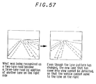
- Japanese Laid-open Patent Application No. Hei 4-36878 teaches a technique for detecting a vehicle lane (road). This prior art enables detection of the presence of a lane to the outside of a broken line insofar as the broken line can be recognized. Since perfect recognition of a broken line as such is not possible under all driving conditions, however, incertainty remains at the time of the lane pattern changes (see Figure 57).
- a second object of the invention is therefore to provide a system for processing lane images for a vehicle capable of responding flexibly to changes in the number of lanes even when the number thereof is unknown.
- the present invention provides a system for processing lane images for a vehicle, including:
- the present invention thus provides a system for processing lane images for a vehicle which enables stable and reliable vehicle self-navigation by setting the regions of the image to be processed such that the lane recognition is unaffected by the presence in the image of a preceding vehicle or other such obstacle and by selecting the optimum lane in a road environment in which obstacles such as other vehicles are present.
- FIG. 1 shows an overall perspective view of the system for processing lane images for a vehicle according to the invention and loaded on a vehicle.
- the system is equipped with an image sensor such as a CCD (charge-coupled device) monochrome TV camera 10.
- the CCD camera (image sensor) 10 is mounted above the driver's seat in the vicinity of the rearview mirror to capture a monocular view of the road ahead.
- the system is further equipped with a radar system 12 comprising of 2 millimeter-wave radars mounted at the front of the vehicle to detect the presence of obstacles such as vehicles and other solid objects from the waves they reflect.
- a yaw rate sensor 14 is mounted near the center of the passenger compartment for detecting the angular acceleration of the vehicle around the gravitational axis (z-axis).
- a vehicle speed sensor 16 constituted as a reed switch is mounted in the vicinity of the vehicle drive shaft (not shown) for detecting the vehicle travel speed
- a steering angle sensor 18 is provided in the vicinity of the steering shaft 20 for detecting the steering angle.
- the steering shaft 20 is equipped with a steering angle control motor 22, the throttle valve (not shown) is equipped with a throttle actuator 24 constituted as a stepping motor, and the brake system (not shown) is equipped with a brake pressure actuator 26 (not shown in Figure 1).
- the vehicle navigates automatically by controlling the steering angle in accordance with a calculated steering angle control amount, adjusting the vehicle speed by controlling the throttle valve opening, and, when necessary, applying the brakes.
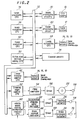
- the aforesaid configuration is shown in detail in the block diagram of Figure 2.
- the output of the CCD camera 10 is sent to image processing circuitry or hardware 30 where straight line segments are extracted by edge detection and Hough transformation, and the result is forwarded through a bus 32 for storage in a common memory 34.
- An image processing CPU 36 extracts lane boundary candidates from among the straight line segments and stores them in the common memory 34.
- An image evaluation CPU 38 reads the stored values at prescribed times and uses them to determine the lane boundaries.
- the output of the radar system 12 is sent through a radar processing circuit 40 and the bus 32 to be stored in the common memory 34.
- a radar evaluation CPU 42 reads the stored values at prescribed times for detecting the positions of obstacles within a coordinate system.
- the outputs from the vehicle speed sensor 16 etc. are sent to a locus estimating CPU 44 for estimating the vehicle locus.
- An action plan decision making CPU 50 produces a desired course based on the stored values.
- the desired course and the estimated vehicle locus are sent to a locus tracking control CPU 46 which decides a locus (desired course) tracking control amount.
- the locus tracking control CPU 46 calculates the steering angle control amount and forwards it to a steering angle control CPU 52 which drives the steering angle control motor 22 through a PWM (pulse width modulation) controller 54 and a driver 56.
- the amount by which the motor is driven is detected by an encoder 58 and used for feedback control.
- a speed/tracking control section of the action plan decision making CPU 50 calculates a desired vehicle body acceleration and forwards it to a vehicle speed control CPU 60.
- the vehicle speed control CPU 60 drives the throttle actuator 24 through an accelerator stepping motor controller 62 and a driver 64 and drives the brake pressure actuator 26 through a brake solenoid controller 66 and a driver 68.
- the amount by which the brake pressure actuator 26 is driven is detected by a pressure sensor 70 and used for secondary feedback control.
- Figure 3 shows the functions of the block diagram of Figure 2.
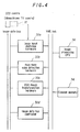
- Figure 4 is a block diagram showing the image processing circuitry or hardware of the block diagram of Figure 2 (the particulars of the system for processing vehicle lane images according to the invention).
- the image processing circuitry or hardware 30 of Figure 4 specifically includes image input digitizing hardware 30a, real-time edge detection hardware 30b, Hough transformation hardware 30c and an image data bus controller 30d.
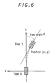
- this is done by, for example, defining the system startup time as time 0 and estimating the movement of the vehicle in an absolute coordinate system whose origin is the position of the vehicle at this time.
- the vehicle's position (x, y) and its yaw angle ⁇ relative to the axis of the coordinate system at time T are calculated by a locus estimating section (the locus estimating CPU 44 in Figure 2) using the speed and yaw rate detected by the vehicle sensors.
- the image processing CPU 36 Prior to image input, receives these data and converts them to information regarding the vehicle position and yaw angle at the time of image input.
- a camera pitch angle correction value is calculated from the amount of vehicle pitch angle variation.
- This is for use in correcting the position and elevation of the CCD camera 10, which change owing to change in the attitude (pitch angle) of the vehicle during acceleration or deceleration. Specifically, this is achieved by mounting height sensors at the four corners of the vehicle (these sensors are omitted from Figures 1 and 2), determining the positional relationship between the vehicle and the road surface, and using the information obtained to correct the camera elevation, thereby preventing errors in mapping calculations between coordinates in the image and coordinates in the actual plane coordinates.
- the lane boundary positions estimated by the image evaluation CPU 38 up to the preceding processing cycle are read and the lane boundaries on the vehicle sides are stored as historical information. This information is an important factor in the setting of the processing region of the image input in the current cycle and the constraints on the straight lines detected by Hough transformation.
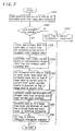
- the estimated lane boundary data up to the preceding cycle are read from the image data estimation.
- the estimated lane boundaries in the actual plane of an image data evaluation such as shown in Figure 8 are read.
- S102 a check is made as to whether lane boundary data are available. Since the result of this discrimination is naturally NO at system startup, the program advances to S104 in which a flag is reset to 0 to indicate "No historical information". On the other hand, if the result of the discrimination in the S102 is YES, the program advances to S106 in which lane boundary data for both sides of the vehicle are derived from all evaluated estimated lane boundary point sequence data. The estimated lane boundary data evaluated by image data evaluation and the vehicle position are assigned IDs from the left side in accordance with the rule set out in Figure 9.
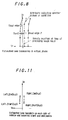
- the start points and end points of approximative straight lines are determined from the lane boundary point sequence data. As shown in Figure 10, this is conducted by selecting the second point of each set of estimated lane boundary point sequence data as the start point and the third point thereof as the end point.
- Figure 11 shows the estimated lane boundary on each side of the vehicle and the selected start and end points.
- the estimated locus data at the time of most recent image input and the estimated locus data at the time of image input in the current cycle are used to correct the start points and end points to the positions at the time of image input in the current cycle.
- the image data evaluation is conducted by converting the four points Left-Start, Left-End, Right-Start and Right-End in the relative coordinate system (Xr1, Yr1) whose origin is the position of the vehicle at the input time T1 of the image which is the most recent image processing result used in the evaluation to points in the relative coordinate system (Xr2, Yr2) at the input time T2 of the image to be processed in the current cycle.
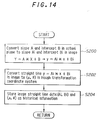
- each (rho, ⁇ ) in the image is calculated from the slope and intercept of each line in the actual plane and the result is stored as historical information. This calculation is conducted by steps S200 to S204 of Figure 14.
- the left and right straight lines Left (slope A_L, intercept B_L) Right (slope A_R, intercept B_R) in the actual plane coordinate system having the vehicle position at the time of current cycle image input as its origin are converted to the lines in the image, the (rho, ⁇ ) values in the Hough transformation coordinate system, namely Left' (rho_L, ⁇ _L) Right' (rho_R, ⁇ _R) are calculated, and the results are stored as "historical information.”
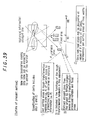
- the origin of the Hough transformation coordinate system in the image is defined as the center of the lower edge of the image
- the length of a line drawn perpendicular to line L from the origin is defined as rho
- the angle thereof measured counterclockwise from the lower edge of the image is defined as ⁇ .
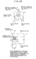
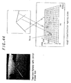
- Camera parameters such as shown in Figure 16 are used in converting positions in the actual plane to positions in the image.
- camera height H 1150 (mm)
- camera elevation Th 0.043 (rad)
- lens focal distance F 12 (mm).
- the imaging element is a 1/2-inch CCD (512 x 512 dot)
- X ⁇ is set to 0.0115 (mm/dot) and Y ⁇ to 0.0095 (mm/dot)
- X ⁇ and Y ⁇ are parameters indicating the length which a single dot in memory assumes in the image plane of the CCD camera 10.
- the program then advances to S116 in the subroutine of Figure 7, wherein a flag is set to 1 to indicate "Historical information available".
- obstacle refers mainly to the preceding vehicle but also includes fixed objects.
- S300 the most recent forward obstacle data are read from the radar data evaluation (radar evaluation CPU 42 in Figure 2).
- S302 a flag is initially reset to 0 to indicate "No obstacle data", whereafter a check is made in S304 as to whether or not obstacle data are available and the number of obstacles is greater than zero.
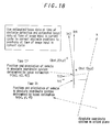
- the program moves to S306, in which estimated locus data at the time of obstacle detection and estimated locus data at the time of image input in the current cycle are used to correct obstacle positions to positions at the time of image input in the current cycle.
- This operation is explained in Figure 18. As shown in this figure, this is conducted by converting the position in the relative coordinate system (Xr1, Yr1) whose origin is the position of the vehicle at the input time T1 of the image which is the most recent image processing result used in the evaluation to points in the relative coordinate system (Xr2, Yr2) at the input time T2 of the image to be processed in the current cycle.
- the obstacle positions (x, y) are substituted into the L and R equations and the obstacle is judged to be within the camera field if y is between the so-obtained yL and yR and also within the length of the inspection zone.
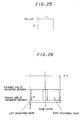
- left and right processing regions that overlap in the middle are set in S500.
- the overlapping of the regions in the middle is for enabling obstacle detection even when the vehicle straddles a lane boundary.
- the set values are stored as the processing regions (Default-L, R).
- each of the left and right processing regions is represented to have a start point (sx, sy) at the upper left and to extend lateral and vertical distances (1x, 1y) from the start point.
- Figure 26 shows the processing regions set in the foregoing manner.
- the nearest side of the recognition distance is set at 5 m and the farthest side at 80 m.
- the positions of the nearest and farthest sides in the image is calculated using an equation for converting from actual plane positions to image positions.
- 16-dot overlaps are provided to the left and right of the image center line. This is to accommodate vehicle tilt relative to the lane boundary during ordinary lane change while driving on an expressway. Further, for avoiding the effect of edge detection processing and other such filtering, 8-dot margins are provided at the left and right edges of the image.
- S404 a check is made as to whether or not obstacle data are available. If the result is YES, the program advances to S406 in which processing forbidden regions are set with respect to the left and right processing regions based on the obstacle position.
- the obstacle referred to here is the preceding vehicle or the like read in S16 of Figure 5.
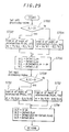
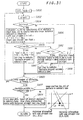
- the subroutine for this processing is shown by the flowchart of Figure 27. The operation is explained in Figure 28.
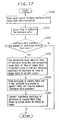
- the obstacle positions are divided into left, right and center zones (S600), the nearest obstacle in each zone is selected (S602), and processing forbidden regions of prescribed width W are set in the respective zones (S604, S606, S608). Since no historical information is available, the processing forbidden regions are centered on the obstacles.
- the predefined detection distance and the slopes and intercepts represented by left and right straight lines are used, first to set a left side processing region according to the direction of the slope by calculating the intersection with the detection distance (S700, S702, S704 and S706) and then to set a right side processing region by similar processing (S708, S710, S712 and S714). Since no obstacle is present in this case, the set regions are substantially the same as those that would be set in S402.
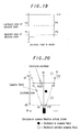
- a counter value is initialized (S800), the value is incremented by 1 (S802), the y-axis value yn of an obstacle in the camera field is confirmed to be less than Ymax (value on the y-axis of the nearest obstacle in the vehicle's lane; explained later) (S804), yn is substituted into the historical information linear equations to obtain x-axis values Lx, Rx (S806), a check is made as to whether or not the x-axis value xn of the obstacle falls between Lx and Rx (S808) and, if it does, a flag indicating that an obstacle is present in the vehicle's lane is set (S810).
- values xn and Lx are compared (S812), whether the obstacle is to the left or right of the vehicle's lane is detected from the result and a flag is set indicating "Obstacle present outside vehicle's lane" (S814, S816, S818).
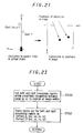
- the program then advances to S414 in the subroutine of Figure 22, where it is determined from the aforesaid flag whether or not an obstacle is present in the vehicle's lane. If the result is YES, left and right processing regions are set in S416 using the distance to the nearest obstacle in the vehicle's lane and the historical information.
- the subroutine for this processing is shown by the flowchart of Figure 32 and the operation is explained in Figure 33.
- the left and right processing regions are set as shown in Figure 33 so as to avoid a region in the vicinity of the obstacle, namely, a region in which the obstacle interferes with detection of the lane boundaries.
- a processing forbidden or prohibited range is set between the left and right regions with the obstacle as a reference.
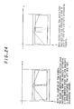
- S420 a check is made as to whether or not an obstacle is present outside the vehicle's lane and, if the result is YES, the program advances to S422 in which processing forbidden regions are set with respect to the established right and left processing regions based on the positions of obstacles present outside the vehicle's lane.
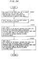
- the details of this operation are shown in the subroutine flowchart of Figure 34 and explained in Figure 35. Specifically, a discrimination is made as to whether the obstacle outside the vehicle's lane is to the left or right (S1000), the nearest obstacle is selected (S1002), and processing forbidden regions of a prescribed width W are set (S1004, S1006).
- the program then moves to S20 in the main routine of Figure 5, where Hough transformation constraints are specified using historical information. This is aimed at eliminating the effect of irregularly appearing shadows, road markers and the like by using the historical information in image data evaluation to conduct preferential segment detection of at least the estimated lane boundaries of the vehicle's lane. It is also for detecting new lane boundaries as they become visible at the time of lane pattern changes or the like.
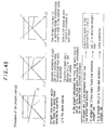
- S1100 a check is made as to whether or not historical information is available and, if the result is YES, the program advances to S1102 and S1104 in which sorting areas for the left and right processing regions are specified. These comprise of predefined fixed areas and variable areas of prescribed size centered on the straight line data of the left and right side historical information. This is illustrated in Figure 38.
- variable areas are set to a width of rho : 32 [dot], ⁇ : 10 [deg] centered on (rho, ⁇ ) of the historical information.
- the fixed areas are set in the range of (rho : 100 - 480 [dot], ⁇ : 98 - 116 [deg]) and (rho : 100 - 480 [dot], ⁇ : 65 - 82 [deg]). If S1100 finds that no historical information is available, two areas of predefined range are set in the left and right processing regions in S1106 and S1108.
- fixed areas are set in the same manner as above, while (rho : 10-380 [dot], ⁇ : 110 - 179 [deg]) and (rho : 10 - 380 [dot], ⁇ : 1 - 70 [deg]) in place of the variable areas.
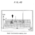
- Sorting areas are set in the Hough transformation (rho, ⁇ ) plane of the current cycle to a prescribed width centered on the historical information (rho, ⁇ ).
- the sorting areas are permanently set at fixed widths. (As will be explained later, straight lines are extracted from the largest to fiftieth largest peaks in the Hough transformation-processed variable and fixed sorting areas.)
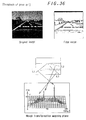
- Figure 40 shows the results of Hough transformation when the present method is applied to the road image of Figure 36. It will be noted that the peak corresponding to the broken line can be easily distinguished.
- the estimated lane boundaries are preferentially extracted from the Hough transformation results using the historical information from the image data evaluation and, similarly, preferential extraction is also conducted in the vicinity of the horizon where the probability of detecting new lane boundaries is high. As a result, it is possible to detect the lane in which the vehicle is traveling with high stability while also maintaining flexibility in response to changes in the lane pattern or in the number of lanes.
- the program proceeds to S22 in the main routine of Figure 5 in which the image is input and its edges are detected.
- the CCD camera 10 image sensor
- the analog NTSC video signal output by the CCD camera (monochrome TV camera) 10 is converted to a 512 x 512 pixels, 8-bit quantized digital image.
- the digital image is imparted with a time delay of the required number of lines (three lines in this embodiment) and input for edge detection processing.
- a sobel operator was used for the edge detection procession.
- the edge detection processing results were output as a 512 x 512 edge image represented at an edge intensity of 8 bits (256 magnitude levels). No particular preprocessing for correction of pixel intensity or noise reduction was conducted. This is because the straight line extraction capability of Hough transformation is very robust to noise and, further, because influence from shadows and road markers other than lane boundaries is adequately prevented by the provision of the constraints at the time the results are selected.
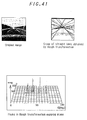
- the edge points in the processing region are Hough transformed. Specifically, in each of the left and right processing regions the edge points of the edge detection processed digital image data having magnitude exceeding the threshold value SLD of the processing region concerned are Hough transformed (according to the "Ohtsu Threshold Value Determination Method," described, for example, in Image Analysis Handbook , P503 (University of Tokyo Publishing Society). The edge points in the processing forbidden regions are not processed.
- representative lines are selected from the Hough transformation results of the left and right regions by clustering. This is for picking out the lane boundaries, i.e. the main line segments, by statistically sorting the group of detected straight lines obtained by Hough transforming a road image such as shown in Figure 41.
- the K-mean method was found to produce the most natural cluster division results.
- the number of clusters can be increased or decreased merely by changing the value of K, while with the other methods it is not clear how many clusters will result until the processing is completed.
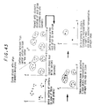
- the clustering method for extracting road lane boundary values was based on the K-mean method, but the number of clusters K thereof was controlled based on the standard deviation within the clusters of the K number of clusters and the capability to unite proximate clusters was added.
- S1200 to S1226 of the flowchart of Figure 42 indicate the operation for clustering the straight line group detected by Hough transformation.
- Figure 43 is a diagram outlining the method used. The procedure, which will not be explained in detail, comprises of evaluating the clustering results by the K-mean method based on the standard deviations within the individual clusters and repeating the processing while increasing/decreasing K (number of clusters).
- the program next advances to S28 in the main routine of Figure 5, in which a check is made for misdetection of the boundaries of the vehicle's lane using road (lane) width.
- the road width in the actual plane is calculated from the two straight lines L1 and L3 and this new road width is used thereafter. The method can therefore deal with changes in road width or some degree of difference between the actual road width and the initially set value.
- the program proceeds to S30 of the main routine of Figure 5 in which the matching between the representative segments and the edge image is checked.
- Japanese Laid-open Patent Application Nos. Hei 3-139706 and Hei 4-36878 teach systems in which the effect of shadows and other such noise is eliminated by setting small processing regions at positions estimated from the processing results in the preceding cycle and curves are coped with by edge inspection and the use of processing regions divided into to far and near sections.
- this method can handle only a prescribed number of lanes and is unable to detect new lane boundaries and lane branches that come into view when changes occur in the lane pattern.
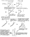
- FIG. 48 This embodiment therefore uses the method shown in Figure 48.
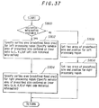
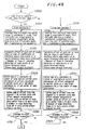
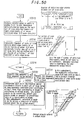
- S1300 to S1334 of the flowchart of Figures 49 and 50 indicate the operation for checking candidate segments against the edge image based on this method.
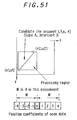
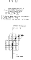
- Figures 51 and 52 are diagrams for explaining the subroutine according to Figure 49.
- the road edges are detected by a heuristic method using the processing results of the preceding cycle.
- the candidate lane boundary point sequences are converted from coordinates in the image to coordinates in the actual plane.
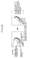
- the aforesaid method requires only detection of the center of edge point distribution on the scanned lines and simple rules for shifting the scanning center, it does not involve any complex conditional branching. Since line segments are obtained by cutting the representative lines selected by clustering after Hough transformation at their intersections, the ensuing processing can be carried out independently for each divided line segment, which makes it possible to achieve high processing speed by processing the segments in parallel.
- the method is less susceptible to horizontal lines resulting from shadows and the like than is the method of investigating and tracking edge points sequentially and is able to cope with broken lines and breaks without need for complex inspection rules.
- the program proceeds to S32 in the main routine of Figure 5 in which the geometric characteristics of the candidate line segments are determined. This involves determining the geometric characteristics of each segment of the lane boundary candidates detected in S30 with respect to the other such segments and attaching the determined characteristics to the output data. These characteristics include, for example, the angles at which each segment connects with other segments.
- the detected lane boundary data is output to the image data evaluation section (the image evaluation CPU 38 in Figure 2) and the program returns to the beginning of the main routine (to S10).
- image processing regions are set based on historical information and obstacle position so that lane recognition is not affected by the preceding vehicle and other obstacles.
- lane recognition errors do not occur when driving behind another vehicle, for example.
- Hough transformation constraints are specified using historical information, changes in the number of lanes can be coped with even in a driving environment with an unknown number of lanes.
Description
Left (slope A_L, intercept B_L)
Right (slope A_R, intercept B_R)
in the actual plane coordinate system having the vehicle position at the time of current cycle image input as its origin are converted to the lines in the image, the (rho, ) values in the Hough transformation coordinate system, namely
Left' (rho_L, _L)
Right' (rho_R, _R)
are calculated, and the results are stored as "historical information." (As shown in Figure 15, in this embodiment the origin of the Hough transformation coordinate system in the image is defined as the center of the lower edge of the image, the length of a line drawn perpendicular to line L from the origin is defined as rho, and the angle thereof measured counterclockwise from the lower edge of the image is defined as .)
Claims (9)
- A system for processing lane images for a vehicle, including:an image sensor (10) mounted on the vehicle for viewing a roadway scene ahead of the vehicle to output image data of the roadway scene including a lane on which the vehicle travels;image data processing means (30) for processing the image data to output lane information;lane recognition means (36) for recognizing the lane on which the vehicle travels based on the output lane information; andobstacle position determining means (12,40,42) for determining the position of an obstacle present in the roadway scene; characterized byprocessing forbidden region setting means (30,S406) for setting a processing forbidden region based on the position of the obstacle; andprocessing region determining means (30, S416) for determining a region of the data image to be processed at least based on the set processing forbidden region such that the region excludes the detected obstacle position.
- A system according to claim 1, wherein said processing region determining means (30) determines the region such that the region is made up of a left half and a right half that overlap partially with each other.
- A system according to claim 1 or 2, further including:lane boundary position storing means (34) for storing a lane boundary position estimated up to a preceding image data processing as historical information; andsaid processing region determining means (30) determines the region based on the set processing forbidden region and the historical information.
- A system according to any of preceding claims 1 to 3, wherein said image data processing means (30) includes:area determining means for determining an area in the image;edge image extracting means (30b) for extracting edge images in the image data of the area;Hough transforming means (30c) for carrying out Hough transformation on the edge images;straight line detecting means for detecting from one from among straight lines obtained from the Hough transformation; andsaid lane recognition means recognizes the lane on which the vehicle travels based on the detected straight line.
- A system according to claim 4, further including:lane boundary position storing means for storing a lane boundary position estimated up to a preceding image data processing as historical information; andsaid area determining means determines a first area based on the historical information and a second area based on a position where a new lane boundary can be expected to appear.
- A system according to claim 5, wherein said area determining means determines the second area based on a position corresponding to a horizon in the roadway scene.
- A system according to any of preceding claims 4 to 6, wherein said straight line detecting means includes;setting means initially setting centers of clusters of the straight lines obtained from the Hough transformation;clustering means for clustering the straight lines obtained from the Hough transformation;defining means for defining an average in each cluster as new centers; anduniting means for uniting proximate clusters to detect said straight line.
- A system according to any of preceding claims 1 to 6, wherein said image sensor is a CCD camera (10).
- A system according to any preceding claim, wherein said processing forbidden region setting means (30,S406) sets the processing forbidden region based on a nearest one among the obstacles determined by said obstacle position determining means.
Applications Claiming Priority (2)
| Application Number | Priority Date | Filing Date | Title |
|---|---|---|---|
| JP18294094A JP3357749B2 (en) | 1994-07-12 | 1994-07-12 | Vehicle road image processing device |
| JP182940/94 | 1994-07-12 |
Publications (3)
| Publication Number | Publication Date |
|---|---|
| EP0697641A2 EP0697641A2 (en) | 1996-02-21 |
| EP0697641A3 EP0697641A3 (en) | 1996-05-01 |
| EP0697641B1 true EP0697641B1 (en) | 1998-10-07 |
Family
ID=16127037
Family Applications (1)
| Application Number | Title | Priority Date | Filing Date |
|---|---|---|---|
| EP95304855A Expired - Lifetime EP0697641B1 (en) | 1994-07-12 | 1995-07-11 | Lane image processing system for vehicle |
Country Status (4)
| Country | Link |
|---|---|
| US (1) | US5790403A (en) |
| EP (1) | EP0697641B1 (en) |
| JP (1) | JP3357749B2 (en) |
| DE (1) | DE69505214T2 (en) |
Cited By (15)
| Publication number | Priority date | Publication date | Assignee | Title |
|---|---|---|---|---|
| EP1705613A1 (en) * | 2005-03-22 | 2006-09-27 | Delphi Technologies, Inc. | Lane marker projection method for a motor vehicle vision system |
| US8818042B2 (en) | 2004-04-15 | 2014-08-26 | Magna Electronics Inc. | Driver assistance system for vehicle |
| US8842176B2 (en) | 1996-05-22 | 2014-09-23 | Donnelly Corporation | Automatic vehicle exterior light control |
| US8917169B2 (en) | 1993-02-26 | 2014-12-23 | Magna Electronics Inc. | Vehicular vision system |
| US8993951B2 (en) | 1996-03-25 | 2015-03-31 | Magna Electronics Inc. | Driver assistance system for a vehicle |
| US9014904B2 (en) | 2004-12-23 | 2015-04-21 | Magna Electronics Inc. | Driver assistance system for vehicle |
| US9171217B2 (en) | 2002-05-03 | 2015-10-27 | Magna Electronics Inc. | Vision system for vehicle |
| US9191574B2 (en) | 2001-07-31 | 2015-11-17 | Magna Electronics Inc. | Vehicular vision system |
| US9205776B2 (en) | 2013-05-21 | 2015-12-08 | Magna Electronics Inc. | Vehicle vision system using kinematic model of vehicle motion |
| US9357208B2 (en) | 2011-04-25 | 2016-05-31 | Magna Electronics Inc. | Method and system for dynamically calibrating vehicular cameras |
| US9436880B2 (en) | 1999-08-12 | 2016-09-06 | Magna Electronics Inc. | Vehicle vision system |
| US9440535B2 (en) | 2006-08-11 | 2016-09-13 | Magna Electronics Inc. | Vision system for vehicle |
| US9491451B2 (en) | 2011-11-15 | 2016-11-08 | Magna Electronics Inc. | Calibration system and method for vehicular surround vision system |
| US9491450B2 (en) | 2011-08-01 | 2016-11-08 | Magna Electronic Inc. | Vehicle camera alignment system |
| US9563951B2 (en) | 2013-05-21 | 2017-02-07 | Magna Electronics Inc. | Vehicle vision system with targetless camera calibration |
Families Citing this family (241)
| Publication number | Priority date | Publication date | Assignee | Title |
|---|---|---|---|---|
| US7339149B1 (en) * | 1993-02-26 | 2008-03-04 | Donnelly Corporation | Vehicle headlight control using imaging sensor |
| JP3357749B2 (en) * | 1994-07-12 | 2002-12-16 | 本田技研工業株式会社 | Vehicle road image processing device |
| JP3120724B2 (en) * | 1996-03-13 | 2000-12-25 | トヨタ自動車株式会社 | Automatic traveling equipment for vehicles |
| US6061628A (en) * | 1996-04-24 | 2000-05-09 | Aisin Aw Co., Ltd. | Navigation system for vehicles |
| JP3556766B2 (en) * | 1996-05-28 | 2004-08-25 | 松下電器産業株式会社 | Road white line detector |
| US5991427A (en) * | 1996-07-31 | 1999-11-23 | Aisin Seiki Kabushiki Kaisha | Method and apparatus for detecting a lane on a road |
| EP0827127B1 (en) * | 1996-08-28 | 2006-10-04 | Matsushita Electric Industrial Co., Ltd. | Local positioning apparatus, and method therefor |
| IT1284976B1 (en) * | 1996-10-17 | 1998-05-28 | Sgs Thomson Microelectronics | METHOD FOR THE IDENTIFICATION OF SIGN STRIPES OF ROAD LANES |
| DE19650863C1 (en) * | 1996-12-07 | 1998-04-16 | Bosch Gmbh Robert | Method of detecting distance sensor vertical adjustment error |
| US5978717A (en) * | 1997-01-17 | 1999-11-02 | Optram, Inc. | Computer system for railway maintenance |
| US6157737A (en) * | 1997-04-04 | 2000-12-05 | Minolta Co., Ltd. | Method of and apparatus for image processing |
| JPH10302050A (en) * | 1997-04-30 | 1998-11-13 | Fujitsu Ltd | Data transformation processing circuit |
| JPH1166488A (en) * | 1997-08-21 | 1999-03-09 | Honda Motor Co Ltd | White line recognizing device |
| JPH1186182A (en) * | 1997-09-01 | 1999-03-30 | Honda Motor Co Ltd | Automatic driving control system |
| JP2986439B2 (en) * | 1998-01-12 | 1999-12-06 | 松下電器産業株式会社 | Vehicle image processing device |
| JPH11213137A (en) * | 1998-01-29 | 1999-08-06 | Matsushita Electric Ind Co Ltd | Image processor |
| GB9804112D0 (en) | 1998-02-27 | 1998-04-22 | Lucas Ind Plc | Road profile prediction |
| US5899956A (en) * | 1998-03-31 | 1999-05-04 | Advanced Future Technologies, Inc. | Vehicle mounted navigation device |
| US6128558A (en) * | 1998-06-09 | 2000-10-03 | Wabtec Railway Electronics, Inc. | Method and apparatus for using machine vision to detect relative locomotive position on parallel tracks |
| JP3307335B2 (en) | 1998-07-22 | 2002-07-24 | 日本電気株式会社 | Vehicle region detection device and vehicle region verification method |
| JP3102478B2 (en) * | 1998-08-17 | 2000-10-23 | 日本電気株式会社 | Linear mark detection method and device |
| KR20000025578A (en) * | 1998-10-13 | 2000-05-06 | 윤종용 | Method for modeling traffic road and method for recognizing traffic lane using the same |
| DE19859345A1 (en) * | 1998-12-22 | 2000-07-06 | Mannesmann Vdo Ag | Device for displaying a control situation determined by a distance control device of a motor vehicle |
| JP2000259998A (en) * | 1999-03-12 | 2000-09-22 | Yazaki Corp | Back monitoring device for vehicle |
| US6226592B1 (en) * | 1999-03-22 | 2001-05-01 | Veridian Erim International, Inc. | Method and apparatus for prompting a motor vehicle operator to remain within a lane |
| JP4007723B2 (en) * | 1999-06-16 | 2007-11-14 | 本田技研工業株式会社 | Vehicle travel safety device |
| KR100305797B1 (en) * | 1999-07-08 | 2001-09-13 | 이계안 | Method for noise removing of the beyond lane alarm device for vehicle |
| JP3808242B2 (en) * | 1999-07-26 | 2006-08-09 | パイオニア株式会社 | Image processing apparatus, image processing method, and navigation apparatus |
| JP3092804B1 (en) * | 1999-09-22 | 2000-09-25 | 富士重工業株式会社 | Driving support device for vehicles |
| CN100533482C (en) * | 1999-11-03 | 2009-08-26 | 特许科技有限公司 | Image processing techniques for a video based traffic monitoring system and methods therefor |
| JP2001134769A (en) * | 1999-11-04 | 2001-05-18 | Honda Motor Co Ltd | Object recognizing device |
| DE19962491A1 (en) * | 1999-12-23 | 2001-07-05 | Daimler Chrysler Ag | Method for the optical monitoring of the surroundings of a moving vehicle |
| JP4647055B2 (en) * | 2000-03-03 | 2011-03-09 | 富士重工業株式会社 | Vehicle motion control device |
| US6396408B2 (en) | 2000-03-31 | 2002-05-28 | Donnelly Corporation | Digital electrochromic circuit with a vehicle network |
| KR100373002B1 (en) * | 2000-04-03 | 2003-02-25 | 현대자동차주식회사 | Method for judgment out of lane of vehicle |
| US6292714B1 (en) * | 2000-05-12 | 2001-09-18 | Fujitsu Limited | Robot cooperation device, and robot cooperation program storage medium |
| JP3539362B2 (en) * | 2000-07-07 | 2004-07-07 | 日産自動車株式会社 | Lane following travel control device |
| US6894606B2 (en) * | 2000-11-22 | 2005-05-17 | Fred Forbes | Vehicular black box monitoring system |
| US7035434B2 (en) * | 2000-12-11 | 2006-04-25 | Texas Instruments Incorporated | Hough transform based motion detection image recording system and method |
| US6498570B2 (en) | 2001-05-24 | 2002-12-24 | Phillip N. Ross | Optical highway line detector |
| US6679181B2 (en) | 2001-05-24 | 2004-01-20 | Richard B. Fox | Dual mode transportation system and method |
| US6741186B2 (en) | 2001-05-24 | 2004-05-25 | Phillip N. Ross | Infrared road line detector |
| JP4156214B2 (en) * | 2001-06-13 | 2008-09-24 | 株式会社デンソー | Vehicle periphery image processing apparatus and recording medium |
| US6934413B2 (en) * | 2001-06-25 | 2005-08-23 | International Business Machines Corporation | Segmentation of text lines in digitized images |
| TWI246665B (en) * | 2001-07-12 | 2006-01-01 | Ding-Jang Tzeng | Method for aiding the driving safety of road vehicle by monocular computer vision |
| US6882287B2 (en) | 2001-07-31 | 2005-04-19 | Donnelly Corporation | Automotive lane change aid |
| US6693557B2 (en) * | 2001-09-27 | 2004-02-17 | Wavetronix Llc | Vehicular traffic sensor |
| SG125895A1 (en) * | 2002-04-04 | 2006-10-30 | Xrgomics Pte Ltd | Reduced keyboard system that emulates qwerty-type mapping and typing |
| US20060061008A1 (en) | 2004-09-14 | 2006-03-23 | Lee Karner | Mounting assembly for vehicle interior mirror |
| US10144353B2 (en) | 2002-08-21 | 2018-12-04 | Magna Electronics Inc. | Multi-camera vision system for a vehicle |
| JP3964287B2 (en) * | 2002-09-04 | 2007-08-22 | 富士重工業株式会社 | Outside-of-vehicle monitoring device and travel control device equipped with this out-of-vehicle monitoring device |
| JP4176430B2 (en) * | 2002-09-18 | 2008-11-05 | 富士重工業株式会社 | Outside-of-vehicle monitoring device and travel control device equipped with this out-of-vehicle monitoring device |
| JP2004117071A (en) | 2002-09-24 | 2004-04-15 | Fuji Heavy Ind Ltd | Vehicle surroundings monitoring apparatus and traveling control system incorporating the same |
| US7426450B2 (en) * | 2003-01-10 | 2008-09-16 | Wavetronix, Llc | Systems and methods for monitoring speed |
| DE10333670B4 (en) | 2003-07-18 | 2019-07-04 | Iav Gmbh Ingenieurgesellschaft Auto Und Verkehr | Method for determining the road course from image data |
| DE10343331A1 (en) * | 2003-09-12 | 2005-04-07 | Valeo Schalter Und Sensoren Gmbh | Method and computer program for detecting the contour of an obstacle in the surroundings of a vehicle |
| US7308341B2 (en) | 2003-10-14 | 2007-12-11 | Donnelly Corporation | Vehicle communication system |
| GB0325990D0 (en) * | 2003-11-07 | 2003-12-10 | Trw Ltd | Method and apparatus for discriminating the colour of road markings |
| JP4281543B2 (en) | 2003-12-16 | 2009-06-17 | 日産自動車株式会社 | VEHICLE DRIVE OPERATION ASSISTANCE DEVICE AND VEHICLE HAVING VEHICLE DRIVE OPERATION ASSISTANCE DEVICE |
| US7349767B2 (en) * | 2003-12-16 | 2008-03-25 | Nissan Motor Co., Ltd. | Method and system for intention estimation and operation assistance |
| JP4226455B2 (en) * | 2003-12-16 | 2009-02-18 | 日産自動車株式会社 | Driving intention estimation device, vehicle driving assistance device, and vehicle equipped with vehicle driving assistance device |
| JP4162618B2 (en) * | 2004-03-12 | 2008-10-08 | 株式会社豊田中央研究所 | Lane boundary judgment device |
| US7482916B2 (en) | 2004-03-15 | 2009-01-27 | Anita Au | Automatic signaling systems for vehicles |
| US7751973B2 (en) * | 2004-05-04 | 2010-07-06 | Visteon Global Technologies, Inc. | Curve warning system |
| JP4092308B2 (en) * | 2004-06-02 | 2008-05-28 | トヨタ自動車株式会社 | Boundary line detection device |
| DE102004028763A1 (en) * | 2004-06-16 | 2006-01-19 | Daimlerchrysler Ag | Andockassistent |
| JP4437714B2 (en) * | 2004-07-15 | 2010-03-24 | 三菱電機株式会社 | Lane recognition image processing device |
| DE102004045585A1 (en) * | 2004-09-17 | 2006-04-06 | Vehico Gmbh | Driving dynamics device for yielding measured values to determine driving dynamics capacities for motor vehicles has devices to scan a marker signal and to evaluate scanned values captured |
| US7974778B2 (en) * | 2004-09-17 | 2011-07-05 | Honda Motor Co., Ltd. | Vehicular control object determination system and vehicular travel locus estimation system |
| US7881496B2 (en) | 2004-09-30 | 2011-02-01 | Donnelly Corporation | Vision system for vehicle |
| US7474961B2 (en) * | 2005-02-04 | 2009-01-06 | Visteon Global Technologies, Inc. | System to determine the path of a vehicle |
| US7782374B2 (en) * | 2005-03-03 | 2010-08-24 | Nissan Motor Co., Ltd. | Processor and processing method for generating a panoramic image for a vehicle |
| JP4539415B2 (en) * | 2005-04-15 | 2010-09-08 | 株式会社デンソー | Image processing device |
| JP4616068B2 (en) * | 2005-04-28 | 2011-01-19 | 本田技研工業株式会社 | Vehicle, image processing system, image processing method, and image processing program |
| JP4715334B2 (en) * | 2005-06-24 | 2011-07-06 | 日産自動車株式会社 | Vehicular image generation apparatus and method |
| JP4046742B2 (en) * | 2005-07-14 | 2008-02-13 | 三菱電機株式会社 | Road shape estimation device |
| JP4185077B2 (en) * | 2005-07-15 | 2008-11-19 | 本田技研工業株式会社 | Vehicle, image processing system, image processing method, and image processing program |
| US7545956B2 (en) * | 2005-08-12 | 2009-06-09 | Visteon Global Technologies, Inc. | Single camera system and method for range and lateral position measurement of a preceding vehicle |
| DE602005017144D1 (en) * | 2005-08-18 | 2009-11-26 | Honda Res Inst Europe Gmbh | Driver assistance system |
| US8248272B2 (en) * | 2005-10-31 | 2012-08-21 | Wavetronix | Detecting targets in roadway intersections |
| US8665113B2 (en) | 2005-10-31 | 2014-03-04 | Wavetronix Llc | Detecting roadway targets across beams including filtering computed positions |
| DE102005055348A1 (en) * | 2005-11-21 | 2007-05-24 | Robert Bosch Gmbh | Device for warning the driver of a motor vehicle |
| US20070150138A1 (en) | 2005-12-08 | 2007-06-28 | James Plante | Memory management in event recording systems |
| US10878646B2 (en) | 2005-12-08 | 2020-12-29 | Smartdrive Systems, Inc. | Vehicle event recorder systems |
| US9201842B2 (en) | 2006-03-16 | 2015-12-01 | Smartdrive Systems, Inc. | Vehicle event recorder systems and networks having integrated cellular wireless communications systems |
| US8996240B2 (en) | 2006-03-16 | 2015-03-31 | Smartdrive Systems, Inc. | Vehicle event recorders with integrated web server |
| JP4661658B2 (en) * | 2006-03-30 | 2011-03-30 | アイシン・エィ・ダブリュ株式会社 | Driving support method, driving support device, and driving support program |
| US8314708B2 (en) | 2006-05-08 | 2012-11-20 | Drivecam, Inc. | System and method for reducing driving risk with foresight |
| US7804426B2 (en) | 2006-05-08 | 2010-09-28 | Drivecam, Inc. | System and method for selective review of event data |
| US20080043736A1 (en) * | 2006-08-18 | 2008-02-21 | Drivecam, Inc. | Data Transfer System and Method |
| US9836716B2 (en) | 2006-05-09 | 2017-12-05 | Lytx, Inc. | System and method for reducing driving risk with hindsight |
| US7659827B2 (en) | 2006-05-08 | 2010-02-09 | Drivecam, Inc. | System and method for taking risk out of driving |
| US20070268158A1 (en) * | 2006-05-09 | 2007-11-22 | Drivecam, Inc. | System and Method for Reducing Driving Risk With Insight |
| US8373567B2 (en) | 2006-05-08 | 2013-02-12 | Drivecam, Inc. | System and method for identifying non-event profiles |
| JP4793094B2 (en) * | 2006-05-17 | 2011-10-12 | 株式会社デンソー | Driving environment recognition device |
| JP4743037B2 (en) * | 2006-07-28 | 2011-08-10 | 株式会社デンソー | Vehicle detection device |
| US8649933B2 (en) | 2006-11-07 | 2014-02-11 | Smartdrive Systems Inc. | Power management systems for automotive video event recorders |
| US8989959B2 (en) | 2006-11-07 | 2015-03-24 | Smartdrive Systems, Inc. | Vehicle operator performance history recording, scoring and reporting systems |
| US8868288B2 (en) | 2006-11-09 | 2014-10-21 | Smartdrive Systems, Inc. | Vehicle exception event management systems |
| US8275170B2 (en) * | 2006-12-08 | 2012-09-25 | Electronics And Telecommunications Research Institute | Apparatus and method for detecting horizon in sea image |
| US8013780B2 (en) * | 2007-01-25 | 2011-09-06 | Magna Electronics Inc. | Radar sensing system for vehicle |
| US7881497B2 (en) * | 2007-03-08 | 2011-02-01 | Honeywell International Inc. | Vision based navigation and guidance system |
| US8184159B2 (en) * | 2007-03-26 | 2012-05-22 | Trw Automotive U.S. Llc | Forward looking sensor system |
| US8239092B2 (en) | 2007-05-08 | 2012-08-07 | Smartdrive Systems Inc. | Distributed vehicle event recorder systems having a portable memory data transfer system |
| US7914187B2 (en) | 2007-07-12 | 2011-03-29 | Magna Electronics Inc. | Automatic lighting system with adaptive alignment function |
| US8017898B2 (en) | 2007-08-17 | 2011-09-13 | Magna Electronics Inc. | Vehicular imaging system in an automatic headlamp control system |
| US8451107B2 (en) | 2007-09-11 | 2013-05-28 | Magna Electronics, Inc. | Imaging system for vehicle |
| WO2009046268A1 (en) | 2007-10-04 | 2009-04-09 | Magna Electronics | Combined rgb and ir imaging sensor |
| JP4744537B2 (en) * | 2008-02-05 | 2011-08-10 | 日立オートモティブシステムズ株式会社 | Driving lane detector |
| US8306270B2 (en) * | 2008-03-21 | 2012-11-06 | Honda Motor Co., Ltd. | Vehicle travel support device, vehicle, vehicle travel support program |
| JP4622001B2 (en) * | 2008-05-27 | 2011-02-02 | トヨタ自動車株式会社 | Road lane marking detection apparatus and road lane marking detection method |
| JP5065210B2 (en) * | 2008-09-17 | 2012-10-31 | トヨタ自動車株式会社 | Lane recognition device |
| DE102009050368A1 (en) | 2008-10-24 | 2010-05-27 | Magna Electronics Europe Gmbh & Co.Kg | Method for automatically calibrating a virtual camera |
| US8964032B2 (en) | 2009-01-30 | 2015-02-24 | Magna Electronics Inc. | Rear illumination system |
| EP2401176B1 (en) | 2009-02-27 | 2019-05-08 | Magna Electronics | Alert system for vehicle |
| US8376595B2 (en) | 2009-05-15 | 2013-02-19 | Magna Electronics, Inc. | Automatic headlamp control |
| US8896686B2 (en) * | 2009-06-23 | 2014-11-25 | Here Global B.V. | Determining a geometric parameter from a single image |
| US8854453B2 (en) * | 2009-06-23 | 2014-10-07 | Here Global B.V. | Determining geographic position information from a single image |
| EP2459416B2 (en) | 2009-07-27 | 2019-12-25 | Magna Electronics Inc. | Parking assist system |
| US9495876B2 (en) | 2009-07-27 | 2016-11-15 | Magna Electronics Inc. | Vehicular camera with on-board microcontroller |
| US8675060B2 (en) * | 2009-08-28 | 2014-03-18 | Indian Institute Of Science | Machine vision based obstacle avoidance system |
| EP2473871B1 (en) | 2009-09-01 | 2015-03-11 | Magna Mirrors Of America, Inc. | Imaging and display system for vehicle |
| KR101276871B1 (en) * | 2009-12-14 | 2013-06-18 | 안동대학교 산학협력단 | Method and apparatus for collision avoidance of vehicle |
| EP2523831B1 (en) | 2010-01-13 | 2015-12-16 | Magna Electronics Inc. | Vehicular camera and method for periodic calibration of vehicular camera |
| JP5471521B2 (en) * | 2010-01-29 | 2014-04-16 | カシオ計算機株式会社 | Image processing apparatus and method, and program |
| US8890955B2 (en) | 2010-02-10 | 2014-11-18 | Magna Mirrors Of America, Inc. | Adaptable wireless vehicle vision system based on wireless communication error |
| US9117123B2 (en) | 2010-07-05 | 2015-08-25 | Magna Electronics Inc. | Vehicular rear view camera display system with lifecheck function |
| US8509982B2 (en) | 2010-10-05 | 2013-08-13 | Google Inc. | Zone driving |
| US9180908B2 (en) | 2010-11-19 | 2015-11-10 | Magna Electronics Inc. | Lane keeping system and lane centering system |
| US9900522B2 (en) | 2010-12-01 | 2018-02-20 | Magna Electronics Inc. | System and method of establishing a multi-camera image using pixel remapping |
| FR2969099B1 (en) * | 2010-12-21 | 2014-09-12 | Peugeot Citroen Automobiles Sa | METHOD FOR MONITORING A FUNCTION OF AID FOR MONITORING A CIRCULATION PATH COMPRISING TWO LINES |
| US9264672B2 (en) | 2010-12-22 | 2016-02-16 | Magna Mirrors Of America, Inc. | Vision display system for vehicle |
| CN102156979B (en) * | 2010-12-31 | 2012-07-04 | 上海电机学院 | Method and system for rapid traffic lane detection based on GrowCut |
| US9085261B2 (en) | 2011-01-26 | 2015-07-21 | Magna Electronics Inc. | Rear vision system with trailer angle detection |
| US9194943B2 (en) | 2011-04-12 | 2015-11-24 | Magna Electronics Inc. | Step filter for estimating distance in a time-of-flight ranging system |
| US9547795B2 (en) | 2011-04-25 | 2017-01-17 | Magna Electronics Inc. | Image processing method for detecting objects using relative motion |
| US9834153B2 (en) | 2011-04-25 | 2017-12-05 | Magna Electronics Inc. | Method and system for dynamically calibrating vehicular cameras |
| EP2720213A4 (en) * | 2011-06-13 | 2015-03-11 | Nissan Motor | Device for determining road profile, onboard image-recognition device, device for adjusting image-capturing axis, and lane-recognition method. |
| US10793067B2 (en) | 2011-07-26 | 2020-10-06 | Magna Electronics Inc. | Imaging system for vehicle |
| DE112012003931T5 (en) | 2011-09-21 | 2014-07-10 | Magna Electronics, Inc. | Image processing system for a motor vehicle with image data transmission and power supply via a coaxial cable |
| WO2013048994A1 (en) | 2011-09-26 | 2013-04-04 | Magna Electronics, Inc. | Vehicle camera image quality improvement in poor visibility conditions by contrast amplification |
| US9146898B2 (en) | 2011-10-27 | 2015-09-29 | Magna Electronics Inc. | Driver assist system with algorithm switching |
| WO2013081985A1 (en) | 2011-11-28 | 2013-06-06 | Magna Electronics, Inc. | Vision system for vehicle |
| US9762880B2 (en) | 2011-12-09 | 2017-09-12 | Magna Electronics Inc. | Vehicle vision system with customized display |
| US10457209B2 (en) | 2012-02-22 | 2019-10-29 | Magna Electronics Inc. | Vehicle vision system with multi-paned view |
| WO2013126715A2 (en) | 2012-02-22 | 2013-08-29 | Magna Electronics, Inc. | Vehicle camera system with image manipulation |
| US8694224B2 (en) | 2012-03-01 | 2014-04-08 | Magna Electronics Inc. | Vehicle yaw rate correction |
| US8948954B1 (en) * | 2012-03-15 | 2015-02-03 | Google Inc. | Modifying vehicle behavior based on confidence in lane estimation |
| US10609335B2 (en) | 2012-03-23 | 2020-03-31 | Magna Electronics Inc. | Vehicle vision system with accelerated object confirmation |
| US8718861B1 (en) | 2012-04-11 | 2014-05-06 | Google Inc. | Determining when to drive autonomously |
| WO2013158592A2 (en) | 2012-04-16 | 2013-10-24 | Magna Electronics, Inc. | Vehicle vision system with reduced image color data processing by use of dithering |
| US10089537B2 (en) | 2012-05-18 | 2018-10-02 | Magna Electronics Inc. | Vehicle vision system with front and rear camera integration |
| KR101428165B1 (en) * | 2012-06-29 | 2014-08-07 | 엘지이노텍 주식회사 | Lane Departure Warning System and Lane Departure Warning Method |
| KR101382902B1 (en) * | 2012-06-29 | 2014-04-23 | 엘지이노텍 주식회사 | Lane Departure Warning System and Lane Departure Warning Method |
| US9728228B2 (en) | 2012-08-10 | 2017-08-08 | Smartdrive Systems, Inc. | Vehicle event playback apparatus and methods |
| DE112013004044T5 (en) * | 2012-08-13 | 2015-05-13 | Honda Motor Co., Ltd. | Road environment recognition device |
| JP5466342B1 (en) * | 2012-08-13 | 2014-04-09 | 本田技研工業株式会社 | Road environment recognition device |
| US9340227B2 (en) | 2012-08-14 | 2016-05-17 | Magna Electronics Inc. | Vehicle lane keep assist system |
| DE102013217430A1 (en) | 2012-09-04 | 2014-03-06 | Magna Electronics, Inc. | Driver assistance system for a motor vehicle |
| CN103679691B (en) * | 2012-09-24 | 2016-11-16 | 株式会社理光 | Continuous lane segmentation object detecting method and device |
| US9558409B2 (en) | 2012-09-26 | 2017-01-31 | Magna Electronics Inc. | Vehicle vision system with trailer angle detection |
| US9446713B2 (en) | 2012-09-26 | 2016-09-20 | Magna Electronics Inc. | Trailer angle detection system |
| US9633564B2 (en) | 2012-09-27 | 2017-04-25 | Google Inc. | Determining changes in a driving environment based on vehicle behavior |
| US8949016B1 (en) * | 2012-09-28 | 2015-02-03 | Google Inc. | Systems and methods for determining whether a driving environment has changed |
| US9723272B2 (en) | 2012-10-05 | 2017-08-01 | Magna Electronics Inc. | Multi-camera image stitching calibration system |
| US9090234B2 (en) | 2012-11-19 | 2015-07-28 | Magna Electronics Inc. | Braking control system for vehicle |
| US9743002B2 (en) | 2012-11-19 | 2017-08-22 | Magna Electronics Inc. | Vehicle vision system with enhanced display functions |
| US10025994B2 (en) | 2012-12-04 | 2018-07-17 | Magna Electronics Inc. | Vehicle vision system utilizing corner detection |
| US9481301B2 (en) | 2012-12-05 | 2016-11-01 | Magna Electronics Inc. | Vehicle vision system utilizing camera synchronization |
| US9063548B1 (en) * | 2012-12-19 | 2015-06-23 | Google Inc. | Use of previous detections for lane marker detection |
| US9081385B1 (en) | 2012-12-21 | 2015-07-14 | Google Inc. | Lane boundary detection using images |
| US9412271B2 (en) | 2013-01-30 | 2016-08-09 | Wavetronix Llc | Traffic flow through an intersection by reducing platoon interference |
| US20140218529A1 (en) | 2013-02-04 | 2014-08-07 | Magna Electronics Inc. | Vehicle data recording system |
| US9092986B2 (en) | 2013-02-04 | 2015-07-28 | Magna Electronics Inc. | Vehicular vision system |
| US10179543B2 (en) | 2013-02-27 | 2019-01-15 | Magna Electronics Inc. | Multi-camera dynamic top view vision system |
| US9688200B2 (en) | 2013-03-04 | 2017-06-27 | Magna Electronics Inc. | Calibration system and method for multi-camera vision system |
| US10027930B2 (en) | 2013-03-29 | 2018-07-17 | Magna Electronics Inc. | Spectral filtering for vehicular driver assistance systems |
| US9327693B2 (en) | 2013-04-10 | 2016-05-03 | Magna Electronics Inc. | Rear collision avoidance system for vehicle |
| US10232797B2 (en) | 2013-04-29 | 2019-03-19 | Magna Electronics Inc. | Rear vision system for vehicle with dual purpose signal lines |
| US9508014B2 (en) | 2013-05-06 | 2016-11-29 | Magna Electronics Inc. | Vehicular multi-camera vision system |
| US10567705B2 (en) | 2013-06-10 | 2020-02-18 | Magna Electronics Inc. | Coaxial cable with bidirectional data transmission |
| US9260095B2 (en) | 2013-06-19 | 2016-02-16 | Magna Electronics Inc. | Vehicle vision system with collision mitigation |
| US20140375476A1 (en) | 2013-06-24 | 2014-12-25 | Magna Electronics Inc. | Vehicle alert system |
| US10755110B2 (en) | 2013-06-28 | 2020-08-25 | Magna Electronics Inc. | Trailering assist system for vehicle |
| US10326969B2 (en) | 2013-08-12 | 2019-06-18 | Magna Electronics Inc. | Vehicle vision system with reduction of temporal noise in images |
| US9619716B2 (en) | 2013-08-12 | 2017-04-11 | Magna Electronics Inc. | Vehicle vision system with image classification |
| US9501878B2 (en) | 2013-10-16 | 2016-11-22 | Smartdrive Systems, Inc. | Vehicle event playback apparatus and methods |
| US9610955B2 (en) | 2013-11-11 | 2017-04-04 | Smartdrive Systems, Inc. | Vehicle fuel consumption monitor and feedback systems |
| US9499139B2 (en) | 2013-12-05 | 2016-11-22 | Magna Electronics Inc. | Vehicle monitoring system |
| US9988047B2 (en) | 2013-12-12 | 2018-06-05 | Magna Electronics Inc. | Vehicle control system with traffic driving control |
| US10160382B2 (en) | 2014-02-04 | 2018-12-25 | Magna Electronics Inc. | Trailer backup assist system |
| US8892310B1 (en) | 2014-02-21 | 2014-11-18 | Smartdrive Systems, Inc. | System and method to detect execution of driving maneuvers |
| KR20150113589A (en) * | 2014-03-31 | 2015-10-08 | 팅크웨어(주) | Electronic apparatus and control method thereof |
| US9623878B2 (en) | 2014-04-02 | 2017-04-18 | Magna Electronics Inc. | Personalized driver assistance system for vehicle |
| US9487235B2 (en) | 2014-04-10 | 2016-11-08 | Magna Electronics Inc. | Vehicle control system with adaptive wheel angle correction |
| US9460624B2 (en) | 2014-05-06 | 2016-10-04 | Toyota Motor Engineering & Manufacturing North America, Inc. | Method and apparatus for determining lane identification in a roadway |
| US10328932B2 (en) | 2014-06-02 | 2019-06-25 | Magna Electronics Inc. | Parking assist system with annotated map generation |
| US9321461B1 (en) | 2014-08-29 | 2016-04-26 | Google Inc. | Change detection using curve alignment |
| US9925980B2 (en) | 2014-09-17 | 2018-03-27 | Magna Electronics Inc. | Vehicle collision avoidance system with enhanced pedestrian avoidance |
| US9248834B1 (en) | 2014-10-02 | 2016-02-02 | Google Inc. | Predicting trajectories of objects based on contextual information |
| US9663127B2 (en) | 2014-10-28 | 2017-05-30 | Smartdrive Systems, Inc. | Rail vehicle event detection and recording system |
| US11069257B2 (en) | 2014-11-13 | 2021-07-20 | Smartdrive Systems, Inc. | System and method for detecting a vehicle event and generating review criteria |
| US10713506B2 (en) | 2014-12-18 | 2020-07-14 | Magna Electronics Inc. | Vehicle vision system with 3D registration for distance estimation |
| US9946940B2 (en) | 2014-12-18 | 2018-04-17 | Magna Electronics Inc. | Vehicle vision system with adaptive lane marker detection |
| JP6483446B2 (en) | 2015-01-15 | 2019-03-13 | トヨタ自動車株式会社 | Composite line determination apparatus and composite line determination method |
| US9916660B2 (en) | 2015-01-16 | 2018-03-13 | Magna Electronics Inc. | Vehicle vision system with calibration algorithm |
| KR101744724B1 (en) * | 2015-03-19 | 2017-06-08 | 현대자동차주식회사 | Audio navigation device, vehicle having the same, user device, and method for controlling vehicle |
| US10286855B2 (en) | 2015-03-23 | 2019-05-14 | Magna Electronics Inc. | Vehicle vision system with video compression |
| US9679420B2 (en) | 2015-04-01 | 2017-06-13 | Smartdrive Systems, Inc. | Vehicle event recording system and method |
| US10946799B2 (en) | 2015-04-21 | 2021-03-16 | Magna Electronics Inc. | Vehicle vision system with overlay calibration |
| US10819943B2 (en) | 2015-05-07 | 2020-10-27 | Magna Electronics Inc. | Vehicle vision system with incident recording function |
| US10449899B2 (en) | 2015-05-08 | 2019-10-22 | Magna Electronics Inc. | Vehicle vision system with road line sensing algorithm and lane departure warning |
| US10214206B2 (en) | 2015-07-13 | 2019-02-26 | Magna Electronics Inc. | Parking assist system for vehicle |
| US9884623B2 (en) * | 2015-07-13 | 2018-02-06 | GM Global Technology Operations LLC | Method for image-based vehicle localization |
| US10078789B2 (en) | 2015-07-17 | 2018-09-18 | Magna Electronics Inc. | Vehicle parking assist system with vision-based parking space detection |
| US10086870B2 (en) | 2015-08-18 | 2018-10-02 | Magna Electronics Inc. | Trailer parking assist system for vehicle |
| US10875403B2 (en) | 2015-10-27 | 2020-12-29 | Magna Electronics Inc. | Vehicle vision system with enhanced night vision |
| US10217363B2 (en) * | 2015-10-29 | 2019-02-26 | Faraday&Future Inc. | Methods and systems for electronically assisted lane entrance |
| US10144419B2 (en) | 2015-11-23 | 2018-12-04 | Magna Electronics Inc. | Vehicle dynamic control system for emergency handling |
| US11277558B2 (en) | 2016-02-01 | 2022-03-15 | Magna Electronics Inc. | Vehicle vision system with master-slave camera configuration |
| US11433809B2 (en) | 2016-02-02 | 2022-09-06 | Magna Electronics Inc. | Vehicle vision system with smart camera video output |
| US10160437B2 (en) | 2016-02-29 | 2018-12-25 | Magna Electronics Inc. | Vehicle control system with reverse assist |
| US20170253237A1 (en) | 2016-03-02 | 2017-09-07 | Magna Electronics Inc. | Vehicle vision system with automatic parking function |
| US10132971B2 (en) | 2016-03-04 | 2018-11-20 | Magna Electronics Inc. | Vehicle camera with multiple spectral filters |
| US10055651B2 (en) | 2016-03-08 | 2018-08-21 | Magna Electronics Inc. | Vehicle vision system with enhanced lane tracking |
| US10121367B2 (en) * | 2016-04-29 | 2018-11-06 | Ford Global Technologies, Llc | Vehicle lane map estimation |
| CN106054886B (en) * | 2016-06-27 | 2019-03-26 | 常熟理工学院 | The identification of automated guided vehicle route and control method based on visible images |
| CA2945564A1 (en) * | 2016-10-18 | 2018-03-01 | Peter Yeung | Roadway information detection sensor device/system for autonomous vehicles |
| US11043124B2 (en) | 2018-01-31 | 2021-06-22 | Peter Yeung | Roadway information detection system consists of sensors on the autonomous vehicles and devices for the road |
| CN106407893B (en) * | 2016-08-29 | 2019-11-22 | 东软集团股份有限公司 | A kind of method, apparatus and equipment detecting lane line |
| US10311551B2 (en) | 2016-12-13 | 2019-06-04 | Westinghouse Air Brake Technologies Corporation | Machine vision based track-occupancy and movement validation |
| US10846541B2 (en) * | 2017-01-04 | 2020-11-24 | Qualcomm Incorporated | Systems and methods for classifying road features |
| US10744941B2 (en) | 2017-10-12 | 2020-08-18 | Magna Electronics Inc. | Vehicle vision system with bird's eye view display |
| US11320284B2 (en) | 2017-12-15 | 2022-05-03 | Regents Of The University Of Minnesota | Real-time lane departure detection using map shape points and trajectory histories |
| US11080562B1 (en) | 2018-06-15 | 2021-08-03 | Apple Inc. | Key point recognition with uncertainty measurement |
| DE102019003238B4 (en) * | 2019-05-08 | 2023-04-20 | Mercedes-Benz Group AG | Vehicle location by map comparison taking into account a street profile |
| CN112630799B (en) * | 2019-09-24 | 2022-11-29 | 阿波罗智能技术(北京)有限公司 | Method and apparatus for outputting information |
| US11946771B2 (en) | 2020-04-01 | 2024-04-02 | Industrial Technology Research Institute | Aerial vehicle and orientation detection method using same |
| CN111523471B (en) * | 2020-04-23 | 2023-08-04 | 阿波罗智联(北京)科技有限公司 | Method, device, equipment and storage medium for determining lane where vehicle is located |
| CN114898325B (en) * | 2022-07-12 | 2022-11-25 | 深圳市城市交通规划设计研究中心股份有限公司 | Vehicle dangerous lane change detection method and device and electronic equipment |
| CN115661267B (en) * | 2022-11-10 | 2023-04-25 | 凌度(广东)智能科技发展有限公司 | Monocular ranging model calibration method, electronic equipment and curtain wall robot |
Family Cites Families (17)
| Publication number | Priority date | Publication date | Assignee | Title |
|---|---|---|---|---|
| JPS62155140A (en) | 1985-12-27 | 1987-07-10 | Aisin Warner Ltd | Road image input system for controlling vehicle |
| JPH0610774B2 (en) | 1987-12-17 | 1994-02-09 | 株式会社クボタ | Imaging type steering control device for automated driving vehicles |
| DE68925091T2 (en) * | 1988-09-28 | 1996-05-09 | Honda Motor Co Ltd | Method and device for estimating the route |
| US5359666A (en) * | 1988-09-28 | 1994-10-25 | Honda Giken Kogyo Kabushiki Kaisha | Driving way judging device and method |
| US4970653A (en) * | 1989-04-06 | 1990-11-13 | General Motors Corporation | Vision method of detecting lane boundaries and obstacles |
| JP2707761B2 (en) | 1989-10-25 | 1998-02-04 | トヨタ自動車株式会社 | Vehicle state quantity measurement device |
| JP2883131B2 (en) | 1989-11-17 | 1999-04-19 | 本田技研工業株式会社 | Driving lane identification method |
| JP2843079B2 (en) * | 1989-12-22 | 1999-01-06 | 本田技研工業株式会社 | Driving path determination method |
| JPH03201110A (en) * | 1989-12-28 | 1991-09-03 | Toyota Central Res & Dev Lab Inc | Position azimuth detecting device for autonomous traveling vehicle |
| JP2754871B2 (en) | 1990-06-01 | 1998-05-20 | 日産自動車株式会社 | Roadway detection device |
| JPH05296767A (en) * | 1992-04-20 | 1993-11-09 | Mitsubishi Electric Corp | Car-to-car distance detector |
| JPH0696397A (en) * | 1992-09-16 | 1994-04-08 | Mitsubishi Electric Corp | Device and method for image tracking |
| JPH06213660A (en) * | 1993-01-19 | 1994-08-05 | Aisin Seiki Co Ltd | Detecting method for approximate straight line of image |
| US5487116A (en) * | 1993-05-25 | 1996-01-23 | Matsushita Electric Industrial Co., Ltd. | Vehicle recognition apparatus |
| JP3169483B2 (en) * | 1993-06-25 | 2001-05-28 | 富士通株式会社 | Road environment recognition device |
| JP3431962B2 (en) * | 1993-09-17 | 2003-07-28 | 本田技研工業株式会社 | Automatic traveling vehicle equipped with a lane marking recognition device |
| JP3357749B2 (en) * | 1994-07-12 | 2002-12-16 | 本田技研工業株式会社 | Vehicle road image processing device |
-
1994
- 1994-07-12 JP JP18294094A patent/JP3357749B2/en not_active Expired - Lifetime
-
1995
- 1995-07-11 US US08/501,232 patent/US5790403A/en not_active Expired - Lifetime
- 1995-07-11 DE DE69505214T patent/DE69505214T2/en not_active Expired - Lifetime
- 1995-07-11 EP EP95304855A patent/EP0697641B1/en not_active Expired - Lifetime
Non-Patent Citations (1)
| Title |
|---|
| S.K. KENUE: "Lanelok: Detection of lane boundaries and vehicule tracking using image-processing techniques", PROCESSING OF THE SPIE (INTERNATIONAL SOCIETY FOR OPTICAL ENGINEERING), MOBILE ROBOTS IV, vol. 1195, 7 November 1989 (1989-11-07), PHILADELPHIA, PA, USA, pages 221 - 245 * |
Cited By (22)
| Publication number | Priority date | Publication date | Assignee | Title |
|---|---|---|---|---|
| US8917169B2 (en) | 1993-02-26 | 2014-12-23 | Magna Electronics Inc. | Vehicular vision system |
| US8993951B2 (en) | 1996-03-25 | 2015-03-31 | Magna Electronics Inc. | Driver assistance system for a vehicle |
| US8842176B2 (en) | 1996-05-22 | 2014-09-23 | Donnelly Corporation | Automatic vehicle exterior light control |
| US9131120B2 (en) | 1996-05-22 | 2015-09-08 | Magna Electronics Inc. | Multi-camera vision system for a vehicle |
| US9436880B2 (en) | 1999-08-12 | 2016-09-06 | Magna Electronics Inc. | Vehicle vision system |
| US9191574B2 (en) | 2001-07-31 | 2015-11-17 | Magna Electronics Inc. | Vehicular vision system |
| US9376060B2 (en) | 2001-07-31 | 2016-06-28 | Magna Electronics Inc. | Driver assist system for vehicle |
| US9555803B2 (en) | 2002-05-03 | 2017-01-31 | Magna Electronics Inc. | Driver assistance system for vehicle |
| US9171217B2 (en) | 2002-05-03 | 2015-10-27 | Magna Electronics Inc. | Vision system for vehicle |
| US9191634B2 (en) | 2004-04-15 | 2015-11-17 | Magna Electronics Inc. | Vision system for vehicle |
| US9428192B2 (en) | 2004-04-15 | 2016-08-30 | Magna Electronics Inc. | Vision system for vehicle |
| US9008369B2 (en) | 2004-04-15 | 2015-04-14 | Magna Electronics Inc. | Vision system for vehicle |
| US8818042B2 (en) | 2004-04-15 | 2014-08-26 | Magna Electronics Inc. | Driver assistance system for vehicle |
| US9193303B2 (en) | 2004-12-23 | 2015-11-24 | Magna Electronics Inc. | Driver assistance system for vehicle |
| US9014904B2 (en) | 2004-12-23 | 2015-04-21 | Magna Electronics Inc. | Driver assistance system for vehicle |
| EP1705613A1 (en) * | 2005-03-22 | 2006-09-27 | Delphi Technologies, Inc. | Lane marker projection method for a motor vehicle vision system |
| US9440535B2 (en) | 2006-08-11 | 2016-09-13 | Magna Electronics Inc. | Vision system for vehicle |
| US9357208B2 (en) | 2011-04-25 | 2016-05-31 | Magna Electronics Inc. | Method and system for dynamically calibrating vehicular cameras |
| US9491450B2 (en) | 2011-08-01 | 2016-11-08 | Magna Electronic Inc. | Vehicle camera alignment system |
| US9491451B2 (en) | 2011-11-15 | 2016-11-08 | Magna Electronics Inc. | Calibration system and method for vehicular surround vision system |
| US9205776B2 (en) | 2013-05-21 | 2015-12-08 | Magna Electronics Inc. | Vehicle vision system using kinematic model of vehicle motion |
| US9563951B2 (en) | 2013-05-21 | 2017-02-07 | Magna Electronics Inc. | Vehicle vision system with targetless camera calibration |
Also Published As
| Publication number | Publication date |
|---|---|
| EP0697641A3 (en) | 1996-05-01 |
| JP3357749B2 (en) | 2002-12-16 |
| DE69505214T2 (en) | 1999-02-25 |
| US5790403A (en) | 1998-08-04 |
| DE69505214D1 (en) | 1998-11-12 |
| JPH0830770A (en) | 1996-02-02 |
| EP0697641A2 (en) | 1996-02-21 |
Similar Documents
| Publication | Publication Date | Title |
|---|---|---|
| EP0697641B1 (en) | Lane image processing system for vehicle | |
| EP0810569B1 (en) | Lane detection sensor and navigation system employing the same | |
| US5307419A (en) | Control device of an autonomously moving body and evaluation method for data thereof | |
| US6091833A (en) | Local positioning apparatus, and a method therefor | |
| US7106886B2 (en) | Road white line recognition apparatus and method | |
| US6489887B2 (en) | Lane-keep assisting system for vehicle | |
| JP3352655B2 (en) | Lane recognition device | |
| US6053268A (en) | Vehicle environment recognition system | |
| Ferryman et al. | Visual surveillance for moving vehicles | |
| Wijesoma et al. | Road-boundary detection and tracking using ladar sensing | |
| EP2422320B1 (en) | Object detection device | |
| US7706572B2 (en) | Obstacle detection system and method therefor | |
| US7266454B2 (en) | Obstacle detection apparatus and method for automotive vehicle | |
| EP1944734B1 (en) | Distance correcting apparatus of surrounding monitoring system and vanishing point correcting apparatus thereof | |
| US7623700B2 (en) | Stereoscopic image processing apparatus and the method of processing stereoscopic images | |
| US20100098295A1 (en) | Clear path detection through road modeling | |
| US20030069695A1 (en) | Apparatus for monitoring area adjacent to vehicle | |
| JPH06266828A (en) | Outside monitoring device for vehicle | |
| GB2313971A (en) | Obstacle tracking by moving vehicle | |
| CN115923839A (en) | Vehicle path planning method | |
| JPH07296291A (en) | Traveling lane detector for vehicle | |
| JP2002132343A (en) | Travel control method for autonomous travel body | |
| Kato et al. | Visual navigation along reference lines and collision avoidance for autonomous vehicles | |
| 後方カメラ用画像処理技術 et al. | Image processing technology for rear view camera (1): Development of lane detection system | |
| JP2001101420A (en) | Device and method for detecting obstacle |
Legal Events
| Date | Code | Title | Description |
|---|---|---|---|
| PUAI | Public reference made under article 153(3) epc to a published international application that has entered the european phase |
Free format text: ORIGINAL CODE: 0009012 |
|
| AK | Designated contracting states |
Kind code of ref document: A2 Designated state(s): DE FR GB |
|
| PUAL | Search report despatched |
Free format text: ORIGINAL CODE: 0009013 |
|
| RHK1 | Main classification (correction) |
Ipc: G05D 1/03 |
|
| AK | Designated contracting states |
Kind code of ref document: A3 Designated state(s): DE FR GB |
|
| 17P | Request for examination filed |
Effective date: 19960906 |
|
| 17Q | First examination report despatched |
Effective date: 19961125 |
|
| GRAG | Despatch of communication of intention to grant |
Free format text: ORIGINAL CODE: EPIDOS AGRA |
|
| GRAG | Despatch of communication of intention to grant |
Free format text: ORIGINAL CODE: EPIDOS AGRA |
|
| GRAH | Despatch of communication of intention to grant a patent |
Free format text: ORIGINAL CODE: EPIDOS IGRA |
|
| GRAH | Despatch of communication of intention to grant a patent |
Free format text: ORIGINAL CODE: EPIDOS IGRA |
|
| GRAA | (expected) grant |
Free format text: ORIGINAL CODE: 0009210 |
|
| AK | Designated contracting states |
Kind code of ref document: B1 Designated state(s): DE FR GB |
|
| REF | Corresponds to: |
Ref document number: 69505214 Country of ref document: DE Date of ref document: 19981112 |
|
| ET | Fr: translation filed | ||
| PLBE | No opposition filed within time limit |
Free format text: ORIGINAL CODE: 0009261 |
|
| STAA | Information on the status of an ep patent application or granted ep patent |
Free format text: STATUS: NO OPPOSITION FILED WITHIN TIME LIMIT |
|
| 26N | No opposition filed | ||
| REG | Reference to a national code |
Ref country code: GB Ref legal event code: IF02 |
|
| PGFP | Annual fee paid to national office [announced via postgrant information from national office to epo] |
Ref country code: FR Payment date: 20090710 Year of fee payment: 15 |
|
| PGFP | Annual fee paid to national office [announced via postgrant information from national office to epo] |
Ref country code: GB Payment date: 20090708 Year of fee payment: 15 |
|
| GBPC | Gb: european patent ceased through non-payment of renewal fee |
Effective date: 20100711 |
|
| REG | Reference to a national code |
Ref country code: FR Ref legal event code: ST Effective date: 20110331 |
|
| PG25 | Lapsed in a contracting state [announced via postgrant information from national office to epo] |
Ref country code: FR Free format text: LAPSE BECAUSE OF NON-PAYMENT OF DUE FEES Effective date: 20100802 |
|
| PG25 | Lapsed in a contracting state [announced via postgrant information from national office to epo] |
Ref country code: GB Free format text: LAPSE BECAUSE OF NON-PAYMENT OF DUE FEES Effective date: 20100711 |
|
| REG | Reference to a national code |
Ref country code: DE Ref legal event code: R084 Ref document number: 69505214 Country of ref document: DE Effective date: 20120523 |
|
| PGFP | Annual fee paid to national office [announced via postgrant information from national office to epo] |
Ref country code: DE Payment date: 20130703 Year of fee payment: 19 |
|
| REG | Reference to a national code |
Ref country code: DE Ref legal event code: R119 Ref document number: 69505214 Country of ref document: DE |
|
| PG25 | Lapsed in a contracting state [announced via postgrant information from national office to epo] |
Ref country code: DE Free format text: LAPSE BECAUSE OF NON-PAYMENT OF DUE FEES Effective date: 20150203 |
|
| REG | Reference to a national code |
Ref country code: DE Ref legal event code: R119 Ref document number: 69505214 Country of ref document: DE Effective date: 20150203 |