EP0698373A2 - Occlusion device for closing an opening in a vessel - Google Patents
Occlusion device for closing an opening in a vessel Download PDFInfo
- Publication number
- EP0698373A2 EP0698373A2 EP95113341A EP95113341A EP0698373A2 EP 0698373 A2 EP0698373 A2 EP 0698373A2 EP 95113341 A EP95113341 A EP 95113341A EP 95113341 A EP95113341 A EP 95113341A EP 0698373 A2 EP0698373 A2 EP 0698373A2
- Authority
- EP
- European Patent Office
- Prior art keywords
- closure
- closure device
- closure body
- locking means
- duct
- Prior art date
- Legal status (The legal status is an assumption and is not a legal conclusion. Google has not performed a legal analysis and makes no representation as to the accuracy of the status listed.)
- Granted
Links
Images

Classifications
-
- A—HUMAN NECESSITIES
- A61—MEDICAL OR VETERINARY SCIENCE; HYGIENE
- A61B—DIAGNOSIS; SURGERY; IDENTIFICATION
- A61B17/00—Surgical instruments, devices or methods, e.g. tourniquets
- A61B17/12—Surgical instruments, devices or methods, e.g. tourniquets for ligaturing or otherwise compressing tubular parts of the body, e.g. blood vessels, umbilical cord
- A61B17/12022—Occluding by internal devices, e.g. balloons or releasable wires
-
- A—HUMAN NECESSITIES
- A61—MEDICAL OR VETERINARY SCIENCE; HYGIENE
- A61B—DIAGNOSIS; SURGERY; IDENTIFICATION
- A61B17/00—Surgical instruments, devices or methods, e.g. tourniquets
- A61B17/0057—Implements for plugging an opening in the wall of a hollow or tubular organ, e.g. for sealing a vessel puncture or closing a cardiac septal defect
-
- A—HUMAN NECESSITIES
- A61—MEDICAL OR VETERINARY SCIENCE; HYGIENE
- A61B—DIAGNOSIS; SURGERY; IDENTIFICATION
- A61B17/00—Surgical instruments, devices or methods, e.g. tourniquets
- A61B17/12—Surgical instruments, devices or methods, e.g. tourniquets for ligaturing or otherwise compressing tubular parts of the body, e.g. blood vessels, umbilical cord
- A61B17/12022—Occluding by internal devices, e.g. balloons or releasable wires
- A61B17/12099—Occluding by internal devices, e.g. balloons or releasable wires characterised by the location of the occluder
- A61B17/12109—Occluding by internal devices, e.g. balloons or releasable wires characterised by the location of the occluder in a blood vessel
-
- A—HUMAN NECESSITIES
- A61—MEDICAL OR VETERINARY SCIENCE; HYGIENE
- A61B—DIAGNOSIS; SURGERY; IDENTIFICATION
- A61B17/00—Surgical instruments, devices or methods, e.g. tourniquets
- A61B17/12—Surgical instruments, devices or methods, e.g. tourniquets for ligaturing or otherwise compressing tubular parts of the body, e.g. blood vessels, umbilical cord
- A61B17/12022—Occluding by internal devices, e.g. balloons or releasable wires
- A61B17/12131—Occluding by internal devices, e.g. balloons or releasable wires characterised by the type of occluding device
- A61B17/12168—Occluding by internal devices, e.g. balloons or releasable wires characterised by the type of occluding device having a mesh structure
- A61B17/12172—Occluding by internal devices, e.g. balloons or releasable wires characterised by the type of occluding device having a mesh structure having a pre-set deployed three-dimensional shape
-
- A—HUMAN NECESSITIES
- A61—MEDICAL OR VETERINARY SCIENCE; HYGIENE
- A61B—DIAGNOSIS; SURGERY; IDENTIFICATION
- A61B17/00—Surgical instruments, devices or methods, e.g. tourniquets
- A61B17/12—Surgical instruments, devices or methods, e.g. tourniquets for ligaturing or otherwise compressing tubular parts of the body, e.g. blood vessels, umbilical cord
- A61B17/12022—Occluding by internal devices, e.g. balloons or releasable wires
- A61B17/12131—Occluding by internal devices, e.g. balloons or releasable wires characterised by the type of occluding device
- A61B17/12181—Occluding by internal devices, e.g. balloons or releasable wires characterised by the type of occluding device formed by fluidized, gelatinous or cellular remodelable materials, e.g. embolic liquids, foams or extracellular matrices
-
- A—HUMAN NECESSITIES
- A61—MEDICAL OR VETERINARY SCIENCE; HYGIENE
- A61B—DIAGNOSIS; SURGERY; IDENTIFICATION
- A61B17/00—Surgical instruments, devices or methods, e.g. tourniquets
- A61B17/0057—Implements for plugging an opening in the wall of a hollow or tubular organ, e.g. for sealing a vessel puncture or closing a cardiac septal defect
- A61B2017/00575—Implements for plugging an opening in the wall of a hollow or tubular organ, e.g. for sealing a vessel puncture or closing a cardiac septal defect for closure at remote site, e.g. closing atrial septum defects
- A61B2017/00592—Elastic or resilient implements
-
- A—HUMAN NECESSITIES
- A61—MEDICAL OR VETERINARY SCIENCE; HYGIENE
- A61B—DIAGNOSIS; SURGERY; IDENTIFICATION
- A61B17/00—Surgical instruments, devices or methods, e.g. tourniquets
- A61B17/0057—Implements for plugging an opening in the wall of a hollow or tubular organ, e.g. for sealing a vessel puncture or closing a cardiac septal defect
- A61B2017/00575—Implements for plugging an opening in the wall of a hollow or tubular organ, e.g. for sealing a vessel puncture or closing a cardiac septal defect for closure at remote site, e.g. closing atrial septum defects
- A61B2017/00601—Implements entirely comprised between the two sides of the opening
-
- A—HUMAN NECESSITIES
- A61—MEDICAL OR VETERINARY SCIENCE; HYGIENE
- A61B—DIAGNOSIS; SURGERY; IDENTIFICATION
- A61B17/00—Surgical instruments, devices or methods, e.g. tourniquets
- A61B17/0057—Implements for plugging an opening in the wall of a hollow or tubular organ, e.g. for sealing a vessel puncture or closing a cardiac septal defect
- A61B2017/00575—Implements for plugging an opening in the wall of a hollow or tubular organ, e.g. for sealing a vessel puncture or closing a cardiac septal defect for closure at remote site, e.g. closing atrial septum defects
- A61B2017/00606—Implements H-shaped in cross-section, i.e. with occluders on both sides of the opening
-
- A—HUMAN NECESSITIES
- A61—MEDICAL OR VETERINARY SCIENCE; HYGIENE
- A61B—DIAGNOSIS; SURGERY; IDENTIFICATION
- A61B17/00—Surgical instruments, devices or methods, e.g. tourniquets
- A61B17/0057—Implements for plugging an opening in the wall of a hollow or tubular organ, e.g. for sealing a vessel puncture or closing a cardiac septal defect
- A61B2017/00575—Implements for plugging an opening in the wall of a hollow or tubular organ, e.g. for sealing a vessel puncture or closing a cardiac septal defect for closure at remote site, e.g. closing atrial septum defects
- A61B2017/00623—Introducing or retrieving devices therefor
-
- A—HUMAN NECESSITIES
- A61—MEDICAL OR VETERINARY SCIENCE; HYGIENE
- A61B—DIAGNOSIS; SURGERY; IDENTIFICATION
- A61B17/00—Surgical instruments, devices or methods, e.g. tourniquets
- A61B17/12—Surgical instruments, devices or methods, e.g. tourniquets for ligaturing or otherwise compressing tubular parts of the body, e.g. blood vessels, umbilical cord
- A61B17/12022—Occluding by internal devices, e.g. balloons or releasable wires
- A61B2017/1205—Introduction devices
Definitions
- the invention relates to a closure device for closing a physical anomaly such as vascular opening such as arterial duct, atrial septal defect, foramen ovale or ventricel septum defect, comprising a closure body extending inside the vascular opening and wire-shaped elastic locking means extending outside the vascular opening.
- the invention further relates to a closure device for closing a physical anomaly such as vascular opening such as arterial duct, atrial septal defect, foramen ovale or ventricel septum defect, comprising a closure body extending within the vascular opening with an axially extending middle part.
- the human blood circulation consists of a cardiovascular and a pulmonary circulation.
- the ductus arteriosus connects the aorta (body circulation) with the pulmonary artery (lung circulation).
- this duct grows after birth.
- pathological development it can happen that the duct does not overgrow, which means that the two blood circuits remain connected even after birth. This can greatly reduce the baby's life expectancy.
- a closure device of the type mentioned at the beginning can be found in DD 233 303 A1.
- the closure body has a single-shell, hyperboloid-like basic shape and can consist of metal, a metal alloy, plastic and similar materials. Extending outside the closure body are wire-shaped locking means, which end at a point, so that there is a risk of injury to the vessel walls.
- the closure device To implant the closure device, it is grasped by a holding wire extending within a securing sleeve and displaced by a catheter. Due to the shape of the closure body and the pointed ends of the locking means there is a risk of serious injury to a patient, the possibility of pulling a misplaced closure device back into the catheter.
- the present invention is based on the problem of developing a closure device of the type described above in such a way that the locking of the closure device within the vessel opening is improved and thus a secure closure is made available.
- the implantation should also be facilitated, with the possibility of correcting incorrect placement without difficulty.
- the problem is essentially solved in that the locking means are spherical or lenticular at their free ends or are provided with spherical or lenticular elements.
- the inventive design of the closure device ensures that injury to the vessel walls by the locking means is excluded. This has the advantage that a change in position of the closure is readily possible when the closure device is implanted.
- the spherical or lenticular ends of the locking means also ensure that when there is a high pressure difference between the vessels connected by the duct, the fixing elements, which normally rest against the inner walls of the vessels, cannot lead to injury due to the movement of the closure device.
- the spherical ends also prevent injury, even if the device may be transported through the vessels without securing the catheter.
- the locking elements which can also be referred to as fixing elements, preferably radiate from the closure body.
- the locking means it is possible to design the locking means as loops, which results in larger contact surfaces for the locking means on the inner walls of the vessel.
- the locking elements exerting a function of spring elements can be made of Platinum, nickel alloys, titanium or other suitable materials.
- a nickel wire with a platinum coating can also be used.
- the spherical or lenticular ends are preferably polished titanium balls or laser welding beads.
- the articulation means with the closure body are fixed in position on the face side by sewing. This ensures that the closure body cannot be moved or compressed due to the pressure difference at the ends of the vessel opening if it is a plastic part.
- the locking means can be connected via a central part extending axially within the closure body. A connection to the locking means assigned to the respective vessels can then take place through the central part.
- the middle part itself can be made in one or more parts like a telescope. Receptacles for the locking means can be formed as openings in the end sections of the middle parts.
- the end sections of the central part can be designed as separate receptacles which are connected to the central part as if welded.
- each duct should be closed as tightly and with as much implantation mass as possible. This also ensures that the space in the guide catheter is always optimally filled, i.e. the implant material (IVALON®) can only be moved onto the application forceps with a little effort.
- the invention provides that these are always sewn to the implant.
- the device can either have a central part or be designed without one.
- At least one locking means extends from its central region and / or the central part extends axially Closure body on a molding such as a clutch, which can be gripped by a pair of guide pliers.
- a molding such as a clutch
- This preferably spherical shape makes it possible for the closure device to be easily handled within a guide catheter by means of flexible guide pliers.
- a particularly noteworthy embodiment of the invention provides that between the closure device and the A safety connection such as thread exists.
- the closure body which is to be referred to as an implant
- the closure body is designed to be rotationally symmetrical and, at least in some areas, frustoconical.
- the implant is inserted in such a way that a tapered side of the implant points towards the vessel with less pressure.
- the surface with an enlarged cross section points towards the vessel with increased pressure.
- the shunt connection is thereby sealed like a wedge. Slipping of the implant within the shunt connection can also be avoided.
- the implant can have a cylindrical base region and a frustoconical tip region, the frustoconical tip region having a surface that either follows a truncated cone shell or a concave shape.
- the base region has a base surface with a diameter D1 which is at least 4 mm larger than an average diameter MD of the implant.
- the mean diameter MD is in the middle of the axial extension of the implant measured at the frustoconical tip area.
- metal wires or bristles projecting from the central part of the closure body and forming a brush-like body.
- a vessel opening is not immediately closed.
- the protruding bristles or wires damage the wall of the opening, which promotes thrombus formation and thus closes the opening.
- plastic fiber threads can also originate from the central part, which also supports thrombus formation.
- wires or bristles extending from the central part also extend outside the vessel opening, these should be end-shaped in the manner described above in the manner of lenses or spheres in order to rule out damage to the vessel walls in this area.
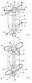
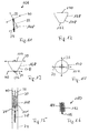
- Fig. 1 shows a first embodiment of a closure device (10), which - without the invention being restricted thereby - is referred to as a duct closure.
- the duct closure (10) unifies a locking device (12) and a preferably cylindrical implant (14) as the closure body.
- the implant (14) can consist of a foam material such as IVALON®, which is characterized in that it is well absorbed by the human body and forms a connection with the surrounding vascular tissue.
- the closure body (14) closing a vessel opening has an opening (16) which is designed to receive the locking device (12).
- the closure body (14) also axially enclose the locking device (12).
- the locking device (12) has a central part (18) which, in a first embodiment, is made in one piece.
- the middle part (18) has end regions (20), (22) into which openings (24), (26), (28) are made, which are used to hold locking means - also fixing elements (30), (32), ( 34) called - serve.
- the central part (18) has a spherical or cylindrical coupling element (38) at an end region (22), preferably spaced apart by a web (36) or a constriction.
- the central part (18), the web (36) and the spherical coupling (38) have a common central axis.
- the middle part (18) is preferably ground or turned from one part, a round material, eg. B. made of titanium or another material such as platinum alloy, with a diameter of about 1 mm to achieve a high degree of flexibility between the end regions (20), (22) to a diameter of about 0.4 mm - 0.6 mm or is rotated.
- the end regions (20), (22) can have a spherical or cylindrical shape.
- the openings (24), (26) made in the end regions (20) run one above the other and are preferably offset from one another by an angle of 90 °.
- the fixing elements (30), (32), (34) can consist of highly elastic titanium wire and have polished laser welding beads (40) at their ends in order to avoid injuries to the vessel walls.
- the ends can also be provided with polished titanium balls, which have a blind hole of approximately 0.3 mm - 0.4 mm in diameter and are welded to the ends of the wire-shaped fixing elements (30), (32), (34).
- Fig. 2 shows a second embodiment of a duct closure (22), which is essentially a modified design of a locking device (44) the embodiment of FIG. 1 differs.
- the locking device (44) has a central part (46), at the ends of which brackets (48), (50) are fastened as welded.
- the brackets (48), (50) have a cylindrical shape and have receptacles (52), (54) for the central part (47).
- a web (56) is molded onto the holder (50) on the side opposite the receptacle (52) and merges into a spherical coupling (58). 1, the center piece (47), the web (56) and the spherical coupling (58) lie on a common central axis.
- the brackets (48), (50) furthermore have receptacles (60) for receiving locking means or fixing or holding elements (62), (64), (66), (68), (70).
- the receptacles (60) are introduced into outer surfaces (72), (74) of the holders (48), (50) lying on a circumferential line.
- the fixing or holding elements (62), (64), (66), (68), (70) are each fastened with their ends in the receptacles (60) of the holding elements (48), (50) .
- the holding or fixing elements (62), (64), (66), (68), (70), which preferably consist of highly elastic titanium wire, are mechanically fixed in the receptacles (60).
- the preferred loop-shaped design of the fixing or holding elements (62), (64), (66), (68), (70) prevents injuries to vessel walls. This also results in the largest possible contact surface on the inner walls of the vessel.
- FIG. 3 shows the duct closure (10) according to FIG. 1 inserted in a guide catheter (74).
- the duct closure (10) lies with its curved fixing elements (30), (32), (34) and the polished laser welding beads or titanium balls ( 40) on an inner wall (76) of the catheter (74).
- the punctiform contact of the duct closure (10) within the catheter (74) enables the duct closure (10) to be moved easily.
- the cylindrical sealing implant such as IVALON® can be easily inserted into the catheter (74) together with the locking device (12), (44).
- the duct closure (10) is held by a flexible guide forceps (78) which is attached to the spherical or cylindrical Coupling (38) of the duct lock (10) engages, held.
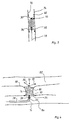
- Fig. 4 shows the duct closure (10) introduced into a duct (80).
- the duct closure (10) is introduced into the duct (80) via the catheter (74), for example from a leg vein via the inferior vena cava, right atrium, right chamber and pulmonary artery (84).
- the catheter (74) or the guiding forceps (78) have diameters which are in the range from 2 mm to 6 mm. Especially with small diameters, e.g. 2.5 mm, it is also possible to treat infants and young children.
- the duct (80) forms the connection between a vessel (82) such as the aorta and another vessel (84) such as the pulmonary artery.
- the duct lock (10) is inserted into the duct (80) by means of the catheter (74).
- the catheter (74) with inserted duct closure (10) is inserted through the pulmonary artery (84) into the duct (80) until an upper edge (86) of the catheter (74) protrudes into the aorta (82).
- the duct lock (10) lies at the level of the duct (80).
- the wall (76) of the catheter (74) is then moved towards the artery (84) with the position of the duct closure (10) held constant, as a result of which the fixing elements (30), (32) move against an inner wall (88) of the aorta ( 82) can create.
- the implant (14) is then exposed so that it can adapt to the inner wall (90) of the duct (80).
- the position of the duct lock (10) is kept constant by the guide pliers (78), which engage the coupling (38) of the duct lock (10).
- the fixing element (34) facing the pulmonary artery (84) is finally exposed, which can thus adapt to the inner wall (92) of the pulmonary artery (84).
- the implant (14) swells due to contact with liquid such as blood, so that the duct (80) is sealed.
- the fixing elements (30), (32), (34) lying against the inner walls (88), (92) cause an axial displacement of the implant (14) due to the high pressure difference between the vessels (82, 84) prevented.
- the implant (14) is sewn to the locking device (12) by means of suture material. This prevents a relative movement between the implant (14) and the locking device (12).
- the flexible can Guide forceps (78) are loosened from the spherical coupling (38) and removed from the pulmonary artery (84).
- the geometry of the implant (14) is designed such that the end regions (20), (22) and the fixing elements (30), (32), (34) are at least partially surrounded by the swollen implant material. The device according to the invention can thus be used to implement a secure duct closure in a simple and inexpensive manner.
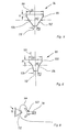
- implants (94), (96) are rotationally symmetrical bodies which are frustoconical at least in some areas and preferably consist of a foam such as Ivalon®.
- the implants (94), (96) essentially consist of a cylindrical base region (98), (100), which is followed by a frustoconical tip region (102), (104).
- the cylindrical base region (98), (100) has a diameter D1 in the range of, for example, 12 to 14 mm, which, however, is preferably at least 4 mm larger than an average diameter MD of the implant (94), (96).
- a diameter of the frustoconical tip region (102), (104) is defined as the mean diameter MD, which is determined in the middle between the base surface (99), (101) and the end surface (110), (112).
- the end surface (110), (112) has a diameter D2, which is preferably in the range between 4 and 6 mm.
- the cylindrical base region (98), (100) has a height H, which is preferably 2 mm.
- the cylindrical base region (98) is followed by a frustoconical tip region (102), the surface (106) of which follows the shape of a truncated cone shell.
- the frustoconical tip region (104) according to FIG. 6 can have a surface (108) which is concave.
- the flexible insertion forceps (78) for the duct closure (10), (42) is shown.
- the insertion forceps (78) has a forceps body (114) which is connected to a handle (118) via a flexible intermediate piece (116).
- the pliers body (114) consists of two cup-shaped claw elements (120), (122) which are connected to an actuating ring (124) of the handle (118) via a linkage (not shown) which runs within the flexible intermediate piece (116) stands.
- the shell-shaped claw elements (120), (122) can be closed by moving the actuating ring (124) in the direction of the arrow (126). A movement of the actuating ring (124) in the direction of the arrow (128), on the other hand, causes the claw elements (120), (122) to open.
- the actuating ring (124) can be locked by a threaded sleeve (130).
- a threaded sleeve 130
- the guide pliers (78) themselves can be held using a holder ring (132).
- the claw elements (120), (122) each have recesses (134), (136) which, when the claw position is closed, form a preferably circular opening (138) in the axial direction of the insertion forceps (78).
- the opening (138) serves to receive the locking means (12), (44) integrally formed web (36), (56), on which the projection (38), (58) is integrally formed like a coupling in the axial extent.
- the molded part (38), (58) is located in a cavity (140) formed by the trough-shaped claws.
- FIG. 7c shows a side view of the claw element (122).
- the claw wall has an opening (142) for receiving a security thread (144) which serves to lock the duct closure (10), (42).
- Fig. 8 shows the securing of the duct lock (10) by means of the security thread (144) on the insertion forceps (78).
- the security thread (144) is guided through the implant (102) and knotted with one end (146) in the opening (142) of the claw element (122).
- the duct lock (10) is also secured by the security thread (144) if the claw elements (120), (122) open unintentionally or if it slips after being decoupled. This reduces the risk of embolism.
- the safety thread (144) is easily pulled through the guide catheter again with the insertion forceps (78).
- middle parts (148) and (150) which extend in the axial direction of a closure body and have end reinforcements (152), (154) which are traversed by locking or fixing means (not shown) are and are connected to them in a mechanical manner.
- the locking means should be sewn to the closure body by triple or double stitching with three knots in order to prevent relative movement of the closure body along the middle part (148) and (150).
- the central part (148) extends with a web-shaped central section (156), within a closure body, not shown.
- the cross-section-enlarged end regions (152) and (154) run at least when the closure device is not implanted outside the closure body.
- each middle part (148), (150) in connection with FIGS. 1, 2, 3 and 4 and serving as a coupling (158) has around the middle part ( 148), (150) and thus the respective closure device to be grasped by an insertion forceps.
- the embodiment according to FIG. 10 can be changed in length in that a web-shaped lower section (160) is telescopically adjustable to the upper and first surrounding section (162). There is preferably a connection between the outer section (162) and the web-shaped inner section (160) via a tension spring (164), which results in an optimal adaptation to the length of a duct to be closed.
- FIG. 11 shows a locking device (166) for a closure device, which can also be referred to as a scaffold, which comprises a central part (148) corresponding to FIG. 9, for example, and locking or fixing elements (30), (32 ), (34) with end polished titanium balls (40).
- a corresponding scaffold (164) is now surrounded by a closure body (168), preferably made of IVALON® and to be designated as a plug, which corresponds to that of FIG. 5, so that reference is made to the relevant statements.
- the locking means (30), (32) and (34) are connected to the end faces (170), (172) of the closure body (168).
- the upper and star-shaped locking elements (30), (32) by means of double seam with three knots, the single-beam locking means (34) are fixed to the end face (172) by means of a triple seam with three knots.
- the corresponding connections are indicated purely in principle by the reference symbols (174) (double seam with three knots) and (176) (triple seam with three knots).
- the preferred embodiment of the closure device shown in FIGS. 11 to 14 does not necessarily have to have the central part (148). Rather, the locking means (30), (32), (34) can be fixed to the closure body (168) solely by sewing them on.
- FIG. 15 A closure device corresponding to the structure of FIGS. 11-14 is shown in FIG. 15 in a position inserted in a guide catheter (74). It can be seen that the plug (168) lies against the inner walls of the catheter (74) and that the locking elements (30), (32) and (34) with their ends (40) consisting of titanium balls on the inner wall of the guide catheter (74 ) issue. Furthermore, the closure device is gripped by means of flexible guiding and fixing pliers (78) via the spherical projection (158). Furthermore, the closure device is connected to the fixing pliers (78) via the security thread (144).
- the frustoconical shape of the plug (168) also has the advantage that the closure device can be pulled back into the guide catheter (74) after the closure device has been removed from it without risk of injury, since the lower locking elements ( 34) can initially rest on the frustoconical section (178) of the plug (168), since there is a free space between the latter and the guide catheter (74); because the diameter of the end face (172) should be smaller than the inside diameter of the guide catheter (74).
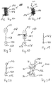
- 16-20 are particularly noteworthy developments of closure devices to remove a vessel opening.
- One of the closure devices (180) shown in FIG. 16 consists of a central part (182) which is coiled as shown in FIGS. 19 and 20 and from which inherently stiff but elastic threads, wires or bristles emanate around a brush-like closure body which forms a closure body Form body (184).
- the protruding threads, wires or bristles should preferably consist of plastic.
- the brush (184) has a cylindrical shape, the threads, wires or bristles leading to injury to the wall inside the vessel opening to an extent such that thrombus formation is promoted when the closure device is introduced into a vessel opening.
- further fibers or other plastic elements can originate from the central part (162), which supports thrombus promotion.
- the middle part (182) has a molded part (186) in order to be gripped by a pair of pliers, as described above.
- FIG. 17 differs from that in FIG. 16 in that longer bristles or wires (190), (192), preferably made of platinum, extend above and below the cylindrical closure body (184), Extend platinum alloy or titanium, which perform the function of the locking means (30), (32), (34) according to FIG. 11 and wax into the end walls of the vessel.
- corresponding locking means (30), (32) and (34) with spherical or lenticular ends (40) made of, for example, titanium can be provided.
- Thrombogenic synthetic threads, fiberglass threads or threads made of natural materials such as cotton can also originate from the middle part (182).
- FIGS. 19 and 20 Middle parts of the closure devices (180), (188) are shown enlarged in FIGS. 19 and 20. It can thus be seen that the central part (182) shown in FIG. 19 is coiled and has the molding (186) on the end.
- the molded part (186) is then located below the enlarged section (198).
- a closure device 200
- the scaffold (166) for example shown in FIG. 11
- a closure body for example made of IVALON®, so that this consists of a central incised section (204) and outer expanded sections (206) and (208).
- the latter sections (206), (208) extend with the locking means (30), (32), (34) running in them and the end balls (40), which are made, for example, of polished titanium, outside the vessel opening to be closed.
- the tapered area (204) then represents the actual closure body.
- closure body itself preferably has a cylindrical or truncated cone shape based on the exemplary embodiments, other geometries are also conceivable; because the shape itself essentially depends on that of the defect to be closed, such as the opening of the vessel. However, a truncated cone shape is preferred for the reasons described above.
- the locking or fixing elements can be straight. Spiral or curved shapes are also conceivable.
- the locking means can also consist of textile or glass fibers or have appropriate materials. Also a coating with plastic or metal is possible.
- the closure body itself can consist of plastic, metal, ceramic or other suitable biocompatible materials. It is also conceivable that the closure body shows a round, square, hexagonal or octagonal geometry in cross section.
Abstract
Description
Die Erfindung bezieht sich auf eine Verschlußeinrichtung zum Verschließen einer körperlichen Anomalie wie Gefäßöffnung wie Ductus arteriosus, Atrium-septum-Defekt, Foramen ovale oder Ventricel-septum-Defekt, umfassend einen sich innerhalb der Gefäßöffnung erstreckenden Verschlußkörper sowie außerhalb der Gefäßöffnung erstreckende drahtförmige elastische Arretierungsmittel. Ferner bezieht sich die Erfindung auf eine Verschlußeinrichtung zum Verschließen einer körperlichen Anomalie wie Gefäßöffnung wie Ductus arteriosus, Atrium-septum-Defekt, Foramen ovale oder Ventricel-septum-Defekt, umfassend einen sich innerhalb der Gefäßöffnung erstreckenden Verschlußkörper mit axial sich erstreckendem Mittelteil.The invention relates to a closure device for closing a physical anomaly such as vascular opening such as arterial duct, atrial septal defect, foramen ovale or ventricel septum defect, comprising a closure body extending inside the vascular opening and wire-shaped elastic locking means extending outside the vascular opening. The invention further relates to a closure device for closing a physical anomaly such as vascular opening such as arterial duct, atrial septal defect, foramen ovale or ventricel septum defect, comprising a closure body extending within the vascular opening with an axially extending middle part.
Der menschliche Blutkreislauf besteht aus einem Herz- und einem Lungenkreislauf. In der embryonalen Phase der Entwicklung eines Menschen sind die beiden Weisläufe durch den Ductus arteriosus miteinander verbunden. Der Ductus verbindet die Aorta (Körperkreislauf) mit der Pulmonalarterie (Lungenkreislauf). Bei einer normalen Entwicklung eines Säuglings verwächst dieser Ductus nach der Geburt. Bei krankhafter Entwicklung kann der Fall eintreten, daß der Ductus nicht zuwächst, wodurch die beiden Blutkreisläufe auch nach der Geburt miteinander verbunden bleiben. Dadurch kann die Lebenserwartung des Säuglings stark reduziert werden.The human blood circulation consists of a cardiovascular and a pulmonary circulation. In the embryonic phase of human development, the two courses of wisdom are connected by the ductus arteriosus. The duct connects the aorta (body circulation) with the pulmonary artery (lung circulation). In the normal development of an infant, this duct grows after birth. In the case of pathological development, it can happen that the duct does not overgrow, which means that the two blood circuits remain connected even after birth. This can greatly reduce the baby's life expectancy.
Es ist bekannt, den Ductus durch einen chirurgischen Eingriff zu verschließen. Dieser Eingriff ist jedoch sehr kostenintensiv und ist mit einem Risiko für den Patienten verbunden.It is known to close the duct by surgery. However, this procedure is very expensive and involves a risk for the patient.
Weiterhin ist es bekannt, den Ductus mittels eines IVALON®-Schaumstoffpfropfens zu verschließen (Porstmann-Technik). Dabei wird eine Leitschiene durch eine Femoralarterie in die Aorta eingeführt, durch den Ductus in die Pulmonalarterie und von dort durch die rechte Herzkammer und den rechten Vorhof und schließlich über die gegenseitige Femoralvene wieder nach außen geführt. Anschließend wird der Ductuspfropfen in den Ductus geschoben, wo er "festgeklemmt" wird. Aufgrund des hohen Druckunterschiedes zwischen Aorta und Pulmonalarterie werden an die Arretierung des Ductuspfropfens innerhalb des Ductus hohe Anforderungen gestellt.It is also known to close the duct using an IVALON® foam plug (Porstmann technology). A guide is inserted through a femoral artery into the aorta, through the duct into the pulmonary artery and from there through the right ventricle and right atrium and finally out through the mutual femoral vein. The duct plug is then pushed into the duct, where it is "clamped". Due to the high pressure difference between the aorta and pulmonary artery, high demands are placed on the locking of the duct plug within the duct.
Daher müssen verhältnismäßig große Pfropfen verwendet werden, die in etwa 10-fach in der Länge gestaucht werden und 30% größer als der Durchmesser des Ductus sind. Entsprechend große Schleusen werden zur Einführung des Pfropfens in die Femoralarterie benötigt. Bei Säuglingen ist das Kaliber der Gefäße zu Klein und oft bei Kindern < 30 kg auch nicht ausreichend für einen derartigen Eingriff.Therefore, relatively large plugs must be used, which are compressed about 10 times in length and 30% larger than the diameter of the duct. Correspondingly large locks are required to insert the graft into the femoral artery. The caliber of the vessels is too small for infants and often not sufficient for such an intervention in children <30 kg.
Eine Verschlußeinrichtung der eingangs genannten Art ist der DD 233 303 A1 zu entnehmen. Bei der bekannten Verschlußeinrichtung weist der Verschlußkörper eine einschalige hyperboloidähnliche Grundform auf und kann aus Metall, einer Metallegierung, Kunststoff und ähnlichen Materialien bestehen. Außerhalb des Verschlußkörpers erstrecken sich drahtförmige Arretierungsmittel, die endseitig spitz auslaufen, so daß die Gefahr von Verletzungen von Gefäßwandungen besteht.A closure device of the type mentioned at the beginning can be found in DD 233 303 A1. In the known closure device, the closure body has a single-shell, hyperboloid-like basic shape and can consist of metal, a metal alloy, plastic and similar materials. Extending outside the closure body are wire-shaped locking means, which end at a point, so that there is a risk of injury to the vessel walls.
Zum Implantieren der Verschlußeinrichtung wird diese von einem sich innerhalb einer Sicherungshülse erstreckendem Haltedraht erfaßt und durch einen Katheter verschoben. Aufgrund der Form des Verschlußkörpers und der spitz zulaufenden Enden der Arretierungsmittel besteht mit erheblicher Verletzungsgefahr für einen Patienten die Möglichkeit, eine fehlgesetzte Verschlußeinrichtung wieder in den Katheter zurückzuziehen.To implant the closure device, it is grasped by a holding wire extending within a securing sleeve and displaced by a catheter. Due to the shape of the closure body and the pointed ends of the locking means there is a risk of serious injury to a patient, the possibility of pulling a misplaced closure device back into the catheter.
Der vorliegenden Erfindung liegt das Problem zugrunde, eine Verschlußeinrichtung der zuvor beschriebenen Art so weiterzubilden, daß die Arretierung der Verschlußeinrichtung innerhalb der Gefäßöffnung verbessert und somit ein sicherer Verschluß zur Verfügung gestellt wird. Auch soll die Implantation erleichert werden, wobei die Möglichkeit gegeben sein soll, Fehlplazierungen ohne Schwierigkeiten zu korrigieren.The present invention is based on the problem of developing a closure device of the type described above in such a way that the locking of the closure device within the vessel opening is improved and thus a secure closure is made available. The implantation should also be facilitated, with the possibility of correcting incorrect placement without difficulty.
Da Problem wird erfindungsgemäß im wesentlichen dadurch gelöst, daß die Arretierungsmittel an ihren freien Enden kugel- oder linsenförmig ausgebildet oder mit kugel- oder linsenförmigen Elementen versehen sind. Durch die erfindungsgemäße Ausbildung der Verschlußeinrichtung ist sichergestellt, daß eine Verletzung der Gefäßwandungen durch die Arretierungsmittel ausgeschlossen wird. Hierdurch ergibt sich der Vorteil, daß beim Implantieren der Verschlußeinrichtung eine Lageveränderung des Verschlusses ohne weiteres möglich ist. Durch die kugel- bzw. linsenförmigen Enden der Arretierungsmittel ist auch gewährleistet, daß bei hohem Druckunterschied der zwischen den durch den Ductus verbundenen Gefäße die Fixierelemente, die normalerweise an den Innenwandungen der Gefäße anliegen, zu einer Verletzung aufgrund der Bewegung der Verschlußeinrichtung nicht führen können. Die kugeligen Enden verhindern auch eine Verletzung, selbst wenn die Vorrichtung gegebenenfalls ohne Sicherung des Katheters durch die Gefäße transportiert wird.According to the invention, the problem is essentially solved in that the locking means are spherical or lenticular at their free ends or are provided with spherical or lenticular elements. The inventive design of the closure device ensures that injury to the vessel walls by the locking means is excluded. This has the advantage that a change in position of the closure is readily possible when the closure device is implanted. The spherical or lenticular ends of the locking means also ensure that when there is a high pressure difference between the vessels connected by the duct, the fixing elements, which normally rest against the inner walls of the vessels, cannot lead to injury due to the movement of the closure device. The spherical ends also prevent injury, even if the device may be transported through the vessels without securing the catheter.
Die auch als Fixierelemente zu bezeichnenden Arretierungselemente gehen dabei vorzugsweise strahlenförmig von dem Verschlußkörper aus. Alternativ besteht die Möglichkeit, die Arretierungsmittel als Schleifen auszubilden, wodurch sich größere Auflageflächen für die Arretierungsmittel an den Innenwandungen der Gefäß ergeben.The locking elements, which can also be referred to as fixing elements, preferably radiate from the closure body. Alternatively, it is possible to design the locking means as loops, which results in larger contact surfaces for the locking means on the inner walls of the vessel.
Die eine Funktion von Federelementen ausübenden Arretierungselemente können aus Platin, Nickel-Legierungen, Titan oder anderen geeigneten Materialien bestehen. Auch kann ein Nickeldraht mit Platinbeschichtung zum Einsatz gelangen. Die kugel- oder linsenförmigen Enden sich vorzugsweise polierte Titankugeln bzw. Laserschweißperlen.The locking elements exerting a function of spring elements can be made of Platinum, nickel alloys, titanium or other suitable materials. A nickel wire with a platinum coating can also be used. The spherical or lenticular ends are preferably polished titanium balls or laser welding beads.
Nach einer besonders hervorzuhebenden Ausgestaltung der Erfindung sind die Artetierungsmittel mit dem Verschlußkörper stirnflächenseitig durch Nähen lagefixiert. Hierdurch ist sichergestellt, daß der Verschlußkörper aufgrund des Druckunterschiedes an den Enden der Gefäßöffnung nicht verschoben bzw. kompremiert werden kann, sofern es sich um ein Kunststoffteil handeln sollte.According to a particularly noteworthy embodiment of the invention, the articulation means with the closure body are fixed in position on the face side by sewing. This ensures that the closure body cannot be moved or compressed due to the pressure difference at the ends of the vessel opening if it is a plastic part.
Die Arretierungsmittel können über ein sich axial innerhalb des Verschlußkörpers erstreckendes Mittelteil verbunden sein. Durch das Mittelteil kann sodann eine Verbindung zu den den jeweiligen Gefäßen zugeordneten Arretierungsmitteln erfolgen. Das Mittelteil selbst kann ein- oder mehrteilig wie teleskopartig ausgebildet sein. Aufnahmen für die Arretierungsmittel können als Durchbrechungen in den Endabschnitten der Mittelteile ausgebildet sein. Die Endabschnitte des Mittelteils können als separate Aufnahmen ausgebildet sein, die mit dem Mittelteil verbunden wie verschweißt sind.The locking means can be connected via a central part extending axially within the closure body. A connection to the locking means assigned to the respective vessels can then take place through the central part. The middle part itself can be made in one or more parts like a telescope. Receptacles for the locking means can be formed as openings in the end sections of the middle parts. The end sections of the central part can be designed as separate receptacles which are connected to the central part as if welded.
Erfindungsgemäß sollte jeder Ductus so dicht und mit so viel Implantationsmasse wie möglich verschlossen werden. Hierdurch ist auch gewährleistet, daß der Raum im Führungskatheter stets optimal ausgefüllt ist, d.h. das Implantationsmaterial (IVALON®) kann nur mit einigem Kraftaufwand auf die Applikationszange verschoben werden. Um ein Lösen oder unkontrolliertes Verschieben des Implantats zu den Arretierungselementen auszuschließen, ist erfindungsgemäß vorgesehen, daß diese stets mit dem Implantat vernäht sind. Um eine optimale Füllung des Ductus zu erreichen, kann die Einrichtung sowohl ein Mittelteil aufweisen als auch ohne ein solches ausgebildet sein.According to the invention, each duct should be closed as tightly and with as much implantation mass as possible. This also ensures that the space in the guide catheter is always optimally filled, i.e. the implant material (IVALON®) can only be moved onto the application forceps with a little effort. In order to rule out loosening or uncontrolled displacement of the implant to the locking elements, the invention provides that these are always sewn to the implant. In order to achieve an optimal filling of the duct, the device can either have a central part or be designed without one.
In einer weiteren Ausbildung der Erfindung weist zumindest ein Arretierungsmittel von dessen Mittenbereich ausgehend und/oder das Mittelteil in axialer Erstreckung des Verschlußkörpers eine Anformung wie Kupplung auf, die von einer Führungszange erfaßbar ist. Durch diese vorzugsweise kugelförmige Anformung ist die Möglichkeit gegeben, daß die Verschlußeinrichtung mittels einer flexiblen Führungszange innerhalb eines Führungskatheters leicht handbar ist.In a further embodiment of the invention, at least one locking means extends from its central region and / or the central part extends axially Closure body on a molding such as a clutch, which can be gripped by a pair of guide pliers. This preferably spherical shape makes it possible for the closure device to be easily handled within a guide catheter by means of flexible guide pliers.
Um nach dem Implantieren der Verschlußeinrichtung ein Lösen von der Führungszange erst dann vorzunehmen, wenn eine ordnungsgemäße Positionierung erfolgt ist bzw. um gegebenenfalls ein Zurückziehen der Verschlußeinrichtung in den Katheter zu ermöglichen, sieht eine besonders hervorzuhebende Ausgestaltung der Erfindung vor, daß zwischen der Verschlußeinrichtung und der Führungszange eine Sicherheitsverbindung wie -faden besteht.In order to only undo the implantation of the guiding forceps after the implantation of the closure device when proper positioning has taken place or to enable the closure device to be withdrawn into the catheter, a particularly noteworthy embodiment of the invention provides that between the closure device and the A safety connection such as thread exists.
Um eine besonders gute Abdichtung der Gefäßöffnung (Shuntverbindung) zu gewährleisten, ist weiterhin vorgesehen, daß der als Implantat zu bezeichnende Verschlußkörper rotationssymmetrisch und zumindest bereichsweise kegelstumpfförmig ausgebildet ist. Das Implantat wird derart eingesetzt, daß eine verjüngte Seite des Implantats in Richtung des Gefäßes mit geringerem Druck zeigt. Die Oberfläche mit vergrößerten, Querschnitt zeigt in Richtung des Gefäßes mit erhöhtem Druck. Dadurch wird die Shuntverbindung keilartig abgedichtet. Auch ein Verrutschen des Implantats innerhalb der Shuntverbindung kann vermieden werden.In order to ensure a particularly good seal of the vessel opening (shunt connection), it is further provided that the closure body, which is to be referred to as an implant, is designed to be rotationally symmetrical and, at least in some areas, frustoconical. The implant is inserted in such a way that a tapered side of the implant points towards the vessel with less pressure. The surface with an enlarged cross section points towards the vessel with increased pressure. The shunt connection is thereby sealed like a wedge. Slipping of the implant within the shunt connection can also be avoided.
In Weiterbildung der Erfindung kann das Implantat einen zylinderförmigen Basisbereich und einen kegelstumpfförmigen Spitzenbereich aufweisen, wobei der kegelstumpfförmige Spitzenbereich eine Oberfläche hat, die entweder einem Kegelstumpfmantel oder einer konkaven Form folgt.In a further development of the invention, the implant can have a cylindrical base region and a frustoconical tip region, the frustoconical tip region having a surface that either follows a truncated cone shell or a concave shape.
Um eine bevorzugte Keilform zu erzielen, weist der Basisbereich eine Basisfläche mit einem Durchmesser D1 auf, der zumindest 4 mm größer ist als ein mittlerer Durchmesser MD des Implantats. Der mittlere Durchmesser MD wird dabei in der Mitte der axialen Erstreckung des Implantats an dem kegelstumpfförmigen Spitzenbereich gemessen.In order to achieve a preferred wedge shape, the base region has a base surface with a diameter D1 which is at least 4 mm larger than an average diameter MD of the implant. The mean diameter MD is in the middle of the axial extension of the implant measured at the frustoconical tip area.
Nach einem selbständigen Lösungsverschlag ist vorgesehen, daß von dem Mittelteil des Verschlußkörpers abragende einen bürstenartigen Körper bildende Metalldrähte oder Borsten ausgehen. Beim Einsetzen eines entsprechend ausgebildeten Verschlußkörpers wird eine Gefäßöffnung zwar nicht unmittelbar verschlossen. Durch die abragenden Borsten oder Drähte wird jedoch die Wandung der Öffnung verletzt, wodurch eine Thrombenbildung gefördert wird und damit ein Verschluß der Öffnung erfolgt. Zusätzlich können von dem Mittelteil Kunststoffaserfäden ausgehen, die ebenfalls die Thrombenbildung unterstützt.After an independent solution, it is provided that metal wires or bristles projecting from the central part of the closure body and forming a brush-like body. When a correspondingly designed closure body is inserted, a vessel opening is not immediately closed. However, the protruding bristles or wires damage the wall of the opening, which promotes thrombus formation and thus closes the opening. In addition, plastic fiber threads can also originate from the central part, which also supports thrombus formation.
Sofern sich auch außerhalb der Gefäßöffnung vom Mittelteil ausgehende Drähte oder Borsten erstrecken, sollten diese endseitig nach der zuvor beschriebenen Art linsen- bzw. bzw. kugelförmig ausgebildet sein, um in diesem Bereich eine Verletzung der Gefäßwandungen auszuschließen.If wires or bristles extending from the central part also extend outside the vessel opening, these should be end-shaped in the manner described above in the manner of lenses or spheres in order to rule out damage to the vessel walls in this area.
Weitere Einzelheiten, Vorteile und Merkmale der Erfindung ergeben sich nicht nur aus den Ansprüchen, den diesen zu entnehmenden Merkmalen - für sich und/oder in Kombination -, sondern auch aus der nachfolgenden Beschreibung von der Zeichnung zu entnehmenden bevorzugten Ausführungsbeispielen.Further details, advantages and features of the invention result not only from the claims, the features to be extracted from them - by themselves and / or in combination - but also from the following description of preferred exemplary embodiments which can be found in the drawing.
Es zeigen:
- Fig. 1
- eine erste Ausführungsform einer Verschlußeinrichtung in perspektivischer Darstellung,
- Fig. 2
- eine zweite Ausführungsform einer Verschlußeinrichtung in perspektivischer Darstellung,
- Fig. 3
- die Verschlußeinrichtung gemäß Fig. 1 eingeführt in einen Führungskatheter,
- Fig. 4
- die an ihrem Einsatzort eingesetzte Verschlußeinrichtung gemäß Fig. 1,
- Fig. 5
- eine erste Ausführungsform eines Verschlußkörpers für einen VE in Schnittdarstellung,
- Fig. 6
- eine zweite Ausführungsform eines Verschlußkörpers in Schnittdarstellung,
- Fig. 7
- eine Einführungszange zum Einführen eines Verschlußeinrichtung durch einen Katheter,
- Fig. 8
- eine über einen Sicherheitsfaden mit der Einführungszange verbundene Verschlußeinrichtung,
- Fig. 9
- eine Detaildarstellung eines Mittelteils einer Verschlußeinrichtung,
- Fig. 10
- eine weitere Ausführungsform eines Mittelteils einer Verschlußeinrichtung,
- Fig. 11
- ein Gerüst einer Verschlußeinrichtung,
- Fig. 12
- eine bevorzugte Ausführungsform eines Verschlußkörpers,
- Fig. 13
- der Verschlußkörper nach Fig. 12 mit mit diesem verbundenen Arretierungsmitteln,
- Fig. 14
- den Verschlußkörper nach Fig. 13 in Draufsicht,
- Fig. 15
- den Verschlußkörper gemäß Fig. 13, positioniert in einem Führungskatheter,
- Fig. 16
- eine weitere hervorzuhebende Ausführungsform einer Verschlußeinrichtung,
- Fig. 17
- eine erste Weiterbildung der Verschlußeinrichtung nach Fig. 16,
- Fig. 18
- eine zweite Weiterbildung der Verschlußeinrichtung nach Fig. 16,
- Fig. 19
- ein für eine Verschlußeinrichtung nach der Fig. 16 oder Fig. 17 geeignetes Mittelteil,
- Fig. 20
- ein für die Verschlußeinrichtung der Fig. 16 oder Fig. 17 geeignetes weiteres Mittelteil und
- Fig. 21
- einen Verschlußkörper mit von diesem umgebenen Gerüst.
- Fig. 1
- a first embodiment of a closure device in a perspective view,
- Fig. 2
- a second embodiment of a closure device in a perspective view,
- Fig. 3
- 1 inserted into a guide catheter,
- Fig. 4
- 1, the closure device used at its place of use,
- Fig. 5
- 1 shows a first embodiment of a closure body for a VE in a sectional view,
- Fig. 6
- 2 shows a second embodiment of a closure body in a sectional view,
- Fig. 7
- an insertion forceps for inserting a closure device through a catheter,
- Fig. 8
- a closure device connected to the insertion forceps via a security thread,
- Fig. 9
- a detailed representation of a central part of a closure device,
- Fig. 10
- another embodiment of a middle part of a closure device,
- Fig. 11
- a framework of a locking device,
- Fig. 12
- a preferred embodiment of a closure body,
- Fig. 13
- 12 with the locking means connected to it,
- Fig. 14
- 13 in top view,
- Fig. 15
- 13, positioned in a guide catheter,
- Fig. 16
- another embodiment of a closure device to be emphasized,
- Fig. 17
- 16 a first development of the closure device according to FIG. 16,
- Fig. 18
- 16 shows a second development of the closure device according to FIG. 16,
- Fig. 19
- a middle part suitable for a closure device according to FIG. 16 or FIG. 17,
- Fig. 20
- a further middle part suitable for the closure device of FIG. 16 or FIG. 17 and
- Fig. 21
- a closure body with the framework surrounded by it.
Fig. 1 zeigt eine erste Ausführungsform einer Verschlußeinrichtung (10), die - ohne daß die Erfindung hierdurch eingeschränkt werden soll -, als Ductusverschluß bezeichnet wird. Der Ductusverschluß (10) unifaßt eine Arretierungsvorrichtung (12) sowie ein vorzugsweise zylinderförmiges Implantat (14) als Verschlußkörper. Das Implantat (14) kann aus einem schaumstofförmigen Material wie IVALON® bestehen, das sich dadurch auszeichnet, daß es vom menschlichen Körper gut aufgenommen wird und mit dem umschließenden Gefäßgewebe eine Verbindung eingeht. Axial weist der eine Gefäßöffnung verschließende Verschlußkörper (14) eine Durchbrechung (16) auf, die zur Aufnahme der Arretierungsvorrichtung (12) ausgebildet ist. Selbstverständlich kann der Verschlußkörper (14) die Arretierungsvorrichtung (12) auch axial umschließen.Fig. 1 shows a first embodiment of a closure device (10), which - without the invention being restricted thereby - is referred to as a duct closure. The duct closure (10) unifies a locking device (12) and a preferably cylindrical implant (14) as the closure body. The implant (14) can consist of a foam material such as IVALON®, which is characterized in that it is well absorbed by the human body and forms a connection with the surrounding vascular tissue. Axially, the closure body (14) closing a vessel opening has an opening (16) which is designed to receive the locking device (12). Of course, the closure body (14) also axially enclose the locking device (12).
Die Arretierungsvorrichtung (12) weist ein Mittelteil (18) auf, das in einer ersten Ausführungsform einteilig ausgebildet ist. Das Mittelteil (18) weist Endbereiche (20), (22) auf, in die Durchbrechungen (24), (26), (28) eingebracht sind, die zur Aufnahme von Arretierungsmitteln - auch Fixierelemente (30), (32), (34) genannt - dienen. Weiterhin weist das Mittelteil (18) an einem Endbereich (22) vorzugsweise durch einen Steg (36) oder eine Einschnürung beabstandet ein kugelförmiges oder zylinderförmiges Kupplungselement (38) auf. Das Mittelteil (18), der Steg (36) und die kugelförmige Kupplung (38) weisen eine gemeinsame Mittelachse auf.The locking device (12) has a central part (18) which, in a first embodiment, is made in one piece. The middle part (18) has end regions (20), (22) into which openings (24), (26), (28) are made, which are used to hold locking means - also fixing elements (30), (32), ( 34) called - serve. Furthermore, the central part (18) has a spherical or cylindrical coupling element (38) at an end region (22), preferably spaced apart by a web (36) or a constriction. The central part (18), the web (36) and the spherical coupling (38) have a common central axis.
Das Mittelteil (18) ist vorzugsweise aus einem Teil geschliffen oder gedreht, wobei ein Rundmaterial, z. B. aus Titan oder einem anderen Material wie Platinlegierung, mit einem Durchmesser von ca. 1 mm zur Erreichung einer hohen Flexibilität zwischen den Endbereichen (20), (22) auf einen Durchmesser von ca. 0,4 mm - 0,6 mm geschliffen oder gedreht wird. Die Endbereiche (20), (22) können eine kugelförmige oder zylindrische Form aufweisen. Die in den Endbereichen (20) eingebrachten Durchbrechungen (24), (26) verlaufen übereinander und sind vorzugsweise um einen Winkel von 90° zueinander versetzt.The middle part (18) is preferably ground or turned from one part, a round material, eg. B. made of titanium or another material such as platinum alloy, with a diameter of about 1 mm to achieve a high degree of flexibility between the end regions (20), (22) to a diameter of about 0.4 mm - 0.6 mm or is rotated. The end regions (20), (22) can have a spherical or cylindrical shape. The openings (24), (26) made in the end regions (20) run one above the other and are preferably offset from one another by an angle of 90 °.
Die Fixierelemente (30), (32), (34) können aus hochelastischem Titandraht bestehen, und weisen an ihren Enden polierte Laserschweißperlen (40) auf, um Verletzungen der Gefäßwände zu vermeiden. Die Enden können auch mit polierten Titankugeln versehen sein, die eine Sacklochbohrung von ca. 0,3 mm - 0,4 mm Durchmesser aufweisen und mit den Enden der drahtförmigen Fixierelemente (30), (32), (34) verschweißt sind.The fixing elements (30), (32), (34) can consist of highly elastic titanium wire and have polished laser welding beads (40) at their ends in order to avoid injuries to the vessel walls. The ends can also be provided with polished titanium balls, which have a blind hole of approximately 0.3 mm - 0.4 mm in diameter and are welded to the ends of the wire-shaped fixing elements (30), (32), (34).
Fig. 2 zeigt eine zweite Ausführungsform eines Ductusverschlusses (22), der sich im wesentlichen durch eine geänderte Gestaltung einer Arretierungsvorrichtung (44) von der Ausführungsform gemäß Fig. 1 unterscheidet. Die Arretierungsvorrichtung (44) weist ein Mittelteil (46) auf, an dessen Enden Halterungen (48), (50) befestigt wie verschweißt sind. Die Halterungen (48), (50) haben eine zylindrische Form und weisen Aufnahmen (52), (54) für das Mittelteil (47) auf. An der Halterung (50) ist an der der Aufnahme (52) gegenüberliegenden Seite ein Steg (56) angeformt, der in eine kugelförmige Kupplung (58) übergeht. Entsprechend Fig. 1 liegen das Mittelstück (47), der Steg (56) und die kugelförmige Kupplung (58) auf einer gemeinsamen Mittelachse.Fig. 2 shows a second embodiment of a duct closure (22), which is essentially a modified design of a locking device (44) the embodiment of FIG. 1 differs. The locking device (44) has a central part (46), at the ends of which brackets (48), (50) are fastened as welded. The brackets (48), (50) have a cylindrical shape and have receptacles (52), (54) for the central part (47). A web (56) is molded onto the holder (50) on the side opposite the receptacle (52) and merges into a spherical coupling (58). 1, the center piece (47), the web (56) and the spherical coupling (58) lie on a common central axis.
Die Halterungen (48), (50) weisen weiterhin Aufnahmen (60) zur Aufnahme von Arretierungsmitteln bzw. Fixier- oder Halteelementen (62), (64), (66), (68), (70) auf. Die Aufnahmen (60) sind in Außenflächen (72), (74) der Halterungen (48), (50) auf einer Umfangslinie liegend eingebracht. Zur Bildung einer Schleife sind die Fixier- bzw. Halteelemente (62), (64), (66), (68), (70) jeweils mit ihren Enden in den Aufnahmen (60) der Halteelemente (48), (50) befestigt. Die Halte- bzw. Fixierelemente (62), (64), (66), (68), (70), die vorzugsweise aus hochelastischem Titandraht bestehen, werden in den Aufnahmen (60) mechanisch fixiert. Durch die bevorzugte schleifenförmige Ausbildung der Fixier- bzw. Halteelemente (62), (64), (66), (68), (70) werden Verletzungen von Gefäßwänden vermieden. Auch wird dadurch eine möglichst große Auflagefläche an den Gefäßinnenwänden erreicht.The brackets (48), (50) furthermore have receptacles (60) for receiving locking means or fixing or holding elements (62), (64), (66), (68), (70). The receptacles (60) are introduced into outer surfaces (72), (74) of the holders (48), (50) lying on a circumferential line. To form a loop, the fixing or holding elements (62), (64), (66), (68), (70) are each fastened with their ends in the receptacles (60) of the holding elements (48), (50) . The holding or fixing elements (62), (64), (66), (68), (70), which preferably consist of highly elastic titanium wire, are mechanically fixed in the receptacles (60). The preferred loop-shaped design of the fixing or holding elements (62), (64), (66), (68), (70) prevents injuries to vessel walls. This also results in the largest possible contact surface on the inner walls of the vessel.
Fig. 3 zeigt den in einen Führungskatheter (74) eingelegten Ductusverschluß (10) gemäß Fig. 1. Der Ductusverschluß (10) liegt dabei mit seinen gebogenen Fixierelementen (30), (32), (34) sowie den polierten Laserschweißperlen oder Titankugeln (40) an einer Innenwandung (76) des Katheters (74) an. Durch das punktförmige Anliegen des Ductusverschlusses (10) innerhalb des Katheters (74) wird ein leichtes Bewegen des Ductusverschlusses (10) ermöglicht. Im ursprünglichen Zustand läßt sich das zylinderförmige Dichtungsimplantat wie IVALON® zusammen mit der Arretierungsvorrichtung (12), (44) leicht in den Katheter (74) einführen. Innerhalb des Katheters wird der Ductusverschluß (10) durch eine flexible Führungszange (78), die an der kugel- beziehungsweise zylinderförmigen Kupplung (38) des Ductusverschlusses (10) eingreift, gehalten.3 shows the duct closure (10) according to FIG. 1 inserted in a guide catheter (74). The duct closure (10) lies with its curved fixing elements (30), (32), (34) and the polished laser welding beads or titanium balls ( 40) on an inner wall (76) of the catheter (74). The punctiform contact of the duct closure (10) within the catheter (74) enables the duct closure (10) to be moved easily. In the original state, the cylindrical sealing implant such as IVALON® can be easily inserted into the catheter (74) together with the locking device (12), (44). Inside the catheter, the duct closure (10) is held by a flexible guide forceps (78) which is attached to the spherical or cylindrical Coupling (38) of the duct lock (10) engages, held.
Fig. 4 zeigt den in einen Ductus (80) eingebrachten Ductusverschuß (10). Der Ductusverschluß (10) wird über den Katheter (74) zum Beispiel von einer Beinvene über untere Hohlvene, rechten Vorhof, rechte Kammer und Pulmonalarterie (84) in den Ductus (80) eingebracht. Der Katheter (74) bzw. die Führungszange (78) weisen Durchmesser auf, die im Bereich von 2 mm bis 6 mm liegen. Insbesondere bei kleinen Durchmessern, wie z.B. 2,5 mm, besteht die Möglichkeit, auch Säuglinge und Kleinkinder zu behandeln.Fig. 4 shows the duct closure (10) introduced into a duct (80). The duct closure (10) is introduced into the duct (80) via the catheter (74), for example from a leg vein via the inferior vena cava, right atrium, right chamber and pulmonary artery (84). The catheter (74) or the guiding forceps (78) have diameters which are in the range from 2 mm to 6 mm. Especially with small diameters, e.g. 2.5 mm, it is also possible to treat infants and young children.
Der Ductus (80) bildet hier die Verbindung zwischen einem Gefäß (82) wie Aorta und einem weiteren Gefäß (84) wie Lungenarterie. In der wie in Fig. 3 gezeigten Anordnung wird der Ductusverschluß (10) mittels des Katheters (74) in den Ductus (80) eingesetzt. Dazu wird der Katheter (74) mit eingelegtem Ductusverschluß (10) durch die Lungenarterie (84) in den Ductus (80) eingeführt, bis eine Oberkante (86) des Katheters (74) in die Aorta (82) hineinragt. Der Ductusverschluß (10) liegt dabei in Höhe des Ductus (80). Anschließend wird die Wandung (76) des Katheters (74) bei konstant gehaltener Position des Ductusverschlusses (10) in Richtung zur Arterie (84) bewegt, wodurch sich die Fixierelemente (30), (32) an einer Innenwandung (88) der Aorta (82) anlegen können. Anschließend wird das Implantat (14) freigelegt, so daß es sich an die Innenwandung (90) des Ductus (80) anpassen kann. Die Position des Ductusverschlusses (10) wird dabei durch die Führungszange (78), die an der Kupplung (38) des Ductusverschlusses (10) angreift, konstant gehalten. Nachdem das Implantant (14) freigelegt ist, wird schließlich das der Lungenarterie (84) zugewandte Fixierelement (34) freigelegt, das sich somit an die Innenwandung (92) der Lungenarterie (84) anpassen kann.The duct (80) forms the connection between a vessel (82) such as the aorta and another vessel (84) such as the pulmonary artery. In the arrangement as shown in FIG. 3, the duct lock (10) is inserted into the duct (80) by means of the catheter (74). For this purpose, the catheter (74) with inserted duct closure (10) is inserted through the pulmonary artery (84) into the duct (80) until an upper edge (86) of the catheter (74) protrudes into the aorta (82). The duct lock (10) lies at the level of the duct (80). The wall (76) of the catheter (74) is then moved towards the artery (84) with the position of the duct closure (10) held constant, as a result of which the fixing elements (30), (32) move against an inner wall (88) of the aorta ( 82) can create. The implant (14) is then exposed so that it can adapt to the inner wall (90) of the duct (80). The position of the duct lock (10) is kept constant by the guide pliers (78), which engage the coupling (38) of the duct lock (10). After the implant (14) is exposed, the fixing element (34) facing the pulmonary artery (84) is finally exposed, which can thus adapt to the inner wall (92) of the pulmonary artery (84).
Durch den Kontakt mit Flüssigkeit wie Blut quillt das Implantat (14) auf, so daß der Ductus (80) dicht verschlossen wird. Durch die an den Innenwandungen (88), (92) anliegenden Fixierelemente (30), (32), (34) wird eine axiale Verschiebung des Implantats (14) aufgrund des hohen Druckunterschiedes zwischen den Gefäßen (82, 84) verhindert. Zur weiteren Fixierung des Implantats ist vorgesehen, daß das Implantat (14) mit der Arretierungsvorrichtung (12) mittels Nahtmaterial vernäht wird. Dadurch wird eine Relativbewegung zwischen Implantat (14) und Arretiervngsvorrichtung (12) unterbunden. Nachdem der Ductusverschluß innerhalb des Ductus (80) eingesetzt ist, und die Fixierelemente (30), (32), (34) an den Innenwandungen (88), (92) der Gefäße (82), (84) anliegen, kann die flexible Führungszange (78) von der kugelförmigen Kupplung (38) gelöst werden und aus der Lungenarterie (84) entfernt werden. Die Geometrie des Implantats (14) ist derart ausgelegt, daß die Endbereiche (20), (22) und die Fixierelemente (30), (32), (34) wenigstens teilweise von dem aufgequollenen Implantatmaterial eingefaßt werden. Durch die erfindungsgemäße Vorrichtung kann somit auf einfache und kostengünstige Weise ein sicherer Ductusverschluß realisiert werden.The implant (14) swells due to contact with liquid such as blood, so that the duct (80) is sealed. The fixing elements (30), (32), (34) lying against the inner walls (88), (92) cause an axial displacement of the implant (14) due to the high pressure difference between the vessels (82, 84) prevented. For further fixation of the implant, it is provided that the implant (14) is sewn to the locking device (12) by means of suture material. This prevents a relative movement between the implant (14) and the locking device (12). After the duct closure is inserted within the duct (80) and the fixing elements (30), (32), (34) rest against the inner walls (88), (92) of the vessels (82), (84), the flexible can Guide forceps (78) are loosened from the spherical coupling (38) and removed from the pulmonary artery (84). The geometry of the implant (14) is designed such that the end regions (20), (22) and the fixing elements (30), (32), (34) are at least partially surrounded by the swollen implant material. The device according to the invention can thus be used to implement a secure duct closure in a simple and inexpensive manner.
Die Fig. 5 und 6 zeigen verschiedene Ausführungsformen von Implantaten (94), (96). Bei den Implantaten (94), (96) handelt es sich um rotationssymmetrische Körper, die zumindest bereichsweise kegelstumpfförmig ausgebildet sind und vorzugsweise aus einem Schaumstoff wie Ivalon® bestehen.5 and 6 show different embodiments of implants (94), (96). The implants (94), (96) are rotationally symmetrical bodies which are frustoconical at least in some areas and preferably consist of a foam such as Ivalon®.
Die Implantate (94), (96) bestehen im wesentlichen aus einem zylinderförmigen Basisbereich (98), (100), an den sich ein kegelstumpfförmiger Spitzenbereich (102), (104) anschließt. Der zylinderförmige Basisbereich (98), (100) weist einen Durchmesser D1 im Bereich von zum Beispiel 12 bis 14 mm auf, der jedoch vorzugsweise zumindest 4 mm größer ist als ein mittlerer Durchmesser MD des Implantats (94), (96). Als mittlerer Durchmesser MD wird ein Durchmesser des kegelstumpfförmigen Spitzenbereichs (102), (104) definiert, der in der Mitte zwischen Basisfläche (99), (101) und Endfläche (110), (112) ermittelt wird. Die Endfläche (110), (112) hat einen Durchmesser D2, der vorzugsweise im Bereich zwischen 4 bis 6 mm liegt. Ferner weist der zylinderförmige Basisbereich (98), (100) eine Höhe H auf, die vorzugsweise 2 mm beträgt.The implants (94), (96) essentially consist of a cylindrical base region (98), (100), which is followed by a frustoconical tip region (102), (104). The cylindrical base region (98), (100) has a diameter D1 in the range of, for example, 12 to 14 mm, which, however, is preferably at least 4 mm larger than an average diameter MD of the implant (94), (96). A diameter of the frustoconical tip region (102), (104) is defined as the mean diameter MD, which is determined in the middle between the base surface (99), (101) and the end surface (110), (112). The end surface (110), (112) has a diameter D2, which is preferably in the range between 4 and 6 mm. Furthermore, the cylindrical base region (98), (100) has a height H, which is preferably 2 mm.
Gemäß Fig. 5 schließt sich an den zylinderförmigen Basisbereich (98) ein kegelstumpfförmiger Spitzenbereich (102) an, dessen Oberfläche (106) der Form eines Kegelstumpfmantels folgt.5, the cylindrical base region (98) is followed by a frustoconical tip region (102), the surface (106) of which follows the shape of a truncated cone shell.
Alternativ kann der kegelstumpfförmige Spitzenbereich (104) gemäß Fig. 6 eine Oberfläche (108) aufweisen, die konkav verläuft.Alternatively, the frustoconical tip region (104) according to FIG. 6 can have a surface (108) which is concave.
In Fig. 7a ist die flexible Einführungszange (78) für den Ductus-Verschluß (10), (42) dargestellt. Die Einführungszange (78) weist einen Zangenkörper (114) auf, die über ein flexibles Zwischenstück (116) mit einer Handhabe (118) verbunden ist. Der Zangenkörper (114) besteht aus zwei schalenförmigen Klauenelementen (120), (122), die über ein Gestänge (nicht dargestellt), welches innerhalb des flexiblen Zwischenstücks (116) verläuft, mit einem Betätigungsring (124) der Handhabe (118) in Verbindung steht. Durch Verschieben des Betätigungsrings (124) in Richtung des Pfeils (126) können die schalenförmigen Klauenelemente (120), (122) verschlossen werden. Eine Bewegung des Betätigungsrings (124) in Richtung des Pfeils (128) hingegen bewirkt ein Öffnen der Klauenelemente (120), (122).In Fig. 7a, the flexible insertion forceps (78) for the duct closure (10), (42) is shown. The insertion forceps (78) has a forceps body (114) which is connected to a handle (118) via a flexible intermediate piece (116). The pliers body (114) consists of two cup-shaped claw elements (120), (122) which are connected to an actuating ring (124) of the handle (118) via a linkage (not shown) which runs within the flexible intermediate piece (116) stands. The shell-shaped claw elements (120), (122) can be closed by moving the actuating ring (124) in the direction of the arrow (126). A movement of the actuating ring (124) in the direction of the arrow (128), on the other hand, causes the claw elements (120), (122) to open.
In geschlossener Stellung der Klauenelemente (120), (122) kann der Betätigungsring (124) durch eine Gewindehülse (130) arretiert werden. Zum Öffnen der Klauen (120), (122) ist somit ein Lösen der Gewindehülse (130) erforderlich, so daß der Betätigungsring (124) in Richtung des Pfeils (128) verschoben werden kann. Die Führungszange (78) selbst kann über einen Halterring (132) gehalten werden.In the closed position of the claw elements (120), (122), the actuating ring (124) can be locked by a threaded sleeve (130). To open the claws (120), (122) it is therefore necessary to loosen the threaded sleeve (130) so that the actuating ring (124) can be moved in the direction of the arrow (128). The guide pliers (78) themselves can be held using a holder ring (132).
Fig. 7b zeigt eine Draufsicht in axialer Richtung auf die Klauenelemente (120), (122), wenn diese sich in geschlossener Stellung befinden. Die Klauenelemente (120), (122) weisen dabei jeweils Aussparungen (134), (136) auf, die bei geschlossener Klauenstellung eine vorzugsweise kreisförmige Öffnung (138) in axialer Richtung der Einführzange (78) bilden. Die Öffnung (138) dient zur Aufnahme des an das Arretierungsmittel (12), (44) angeformten Steges (36), (56), an den in axialer Erstreckung die Anformung (38), (58) wie Kupplung angeformt ist. In geschlossener Stellung der Klauen (120), (122) befindet sich die Anformung (38), (58) in einem durch die wannenförmigen Klauen ausgebildeten Hohlraum (140).7b shows a top view in the axial direction of the claw elements (120), (122) when they are in the closed position. The claw elements (120), (122) each have recesses (134), (136) which, when the claw position is closed, form a preferably circular opening (138) in the axial direction of the insertion forceps (78). The opening (138) serves to receive the locking means (12), (44) integrally formed web (36), (56), on which the projection (38), (58) is integrally formed like a coupling in the axial extent. In the closed position of the claws (120), (122), the molded part (38), (58) is located in a cavity (140) formed by the trough-shaped claws.
Fig. 7c zeigt eine Seitenansicht des Klauenelementes (122). Die Klauenwandung weist eine Durchbrechung (142) zur Aufnahme eines Sicherheitsfadens (144) auf, der zur Arretierung des Ductus-Verschlußes (10), (42) dient.7c shows a side view of the claw element (122). The claw wall has an opening (142) for receiving a security thread (144) which serves to lock the duct closure (10), (42).
Fig. 8 zeigt die Sicherung des Ductus-Verschlußes (10) mittels des Sicherheitsfadens (144) an der Einführungszange (78). Dazu wird der Sicherheitsfaden (144) durch das Implantat (102) geführt und mit einem Ende (146) in der Öffnung (142) des Klauenelementes (122) verknotet. Durch den Sicherheitsfaden (144) ist der Ductus-Verschluß (10) auch dann gesichert, wenn die Klauenelemente (120), (122) unbeabsichtigt öffnen, oder wenn dieser nach gewolltem Abkoppeln verrutscht. Die Gefahr einer Embolie wird dadurch vermindert. Nach gelungener Implantation wird der Sicherheitsfaden (144) problemlos mit der Einführungszange (78) wieder durch den Führungskatheter gezogen.Fig. 8 shows the securing of the duct lock (10) by means of the security thread (144) on the insertion forceps (78). For this purpose, the security thread (144) is guided through the implant (102) and knotted with one end (146) in the opening (142) of the claw element (122). The duct lock (10) is also secured by the security thread (144) if the claw elements (120), (122) open unintentionally or if it slips after being decoupled. This reduces the risk of embolism. After successful implantation, the safety thread (144) is easily pulled through the guide catheter again with the insertion forceps (78).
In den Fig. 9 und 10 sind besondere Ausführungsformen von Mittelteilen (148) und (150) dargestellt, die sich in axialer Richtung eines Verschlußkörpers erstrecken und endseitige Verstärkungen (152), (154) aufweisen, die von nicht dargestellten Arretierungs- oder Fixiermitteln durchsetzt sind und mit diesen auf mechanische Weise verbunden werden. Zusätzlich sollten die Arretierungsmittel mit dem Verschlußkörper durch Dreifach- bzw. Doppelnaht mit drei Knoten vernäht werden, um eine Relativbewegung des Verschlußkörpers entlang des Mittelteils (148) und (150) zu unterbinden.9 and 10 show special embodiments of middle parts (148) and (150) which extend in the axial direction of a closure body and have end reinforcements (152), (154) which are traversed by locking or fixing means (not shown) are and are connected to them in a mechanical manner. In addition, the locking means should be sewn to the closure body by triple or double stitching with three knots in order to prevent relative movement of the closure body along the middle part (148) and (150).
Das Mittelteil (148) erstreckt sich mit einem stegförmigen Mittelabschnitt (156), innerhalb eines nicht dargestellten Verschlußkörpers. Die querschnittvergrößerten Endbereiche (152) und (154) verlaufen zumindest im nicht implantierten Zustand der Verschlußeinrichtung außerhalb des Verschlußkörpers.The central part (148) extends with a web-shaped central section (156), within a closure body, not shown. The cross-section-enlarged end regions (152) and (154) run at least when the closure device is not implanted outside the closure body.
Endseitig, und zwar im Bereich des verstärkten Endes (154) weist jedes Mittelteil (148), (150) im Zusammenhang mit den Fig. 1, 2, 3 und 4 beschriebene und als Kupplung dienende Anformungen (158) auf, um das Mittelteil (148), (150) und damit die jeweilige Verschlußeinrichtung von einer Einführungszange zu erfassen.At the end, namely in the area of the reinforced end (154), each middle part (148), (150) in connection with FIGS. 1, 2, 3 and 4 and serving as a coupling (158) has around the middle part ( 148), (150) and thus the respective closure device to be grasped by an insertion forceps.
Ist das Mittelteil (148) gemäß Fig. 9 einteilig ausgebildet, so weist die Ausführungsform nach Fig. 10 eine Längenveränderbarkeit dadurch auf, daß ein stegförmiger unterer Abschnitt (160) teleskopartig zum oberen und ersteren umgebenden Abschnitt (162) verstellbar ist. Dabei besteht zwischen dem äußeren Abschnitt (162) und dem stegförmigen inneren Abschnitt (160) vorzugsweise eine Verbindung über eine Zugfeder (164), wodurch sich eine optimale Anpassung an die Länge eines zu verschließenden Ductus ergibt.If the middle part (148) according to FIG. 9 is made in one piece, the embodiment according to FIG. 10 can be changed in length in that a web-shaped lower section (160) is telescopically adjustable to the upper and first surrounding section (162). There is preferably a connection between the outer section (162) and the web-shaped inner section (160) via a tension spring (164), which results in an optimal adaptation to the length of a duct to be closed.
In Fig. 11 ist eine auch als Gerüst zu bezeichnende Arretierungsvorrichtung (166) für eine Verschlußeinrichtung dargestellt, die aus einem zum Beispiel der Fig. 9 entsprechendem Mittelteil (148) sowie endseitig von diesem ausgehenden Arretierungs- bzw. Fixierelementen (30), (32), (34) mit endseitigen polierten Titankugeln (40) besteht.FIG. 11 shows a locking device (166) for a closure device, which can also be referred to as a scaffold, which comprises a central part (148) corresponding to FIG. 9, for example, and locking or fixing elements (30), (32 ), (34) with end polished titanium balls (40).
Ein entsprechendes Gerüst (164) wird nunmehr von einem vorzugsweise aus IVALON® bestehenden und als Pfropfen zu bezeichnenden Verschlußkörper (168) umgeben, der dein der Fig. 5 entspricht, so daß auf die diesbezüglichen Ausführungen verwiesen werden.A corresponding scaffold (164) is now surrounded by a closure body (168), preferably made of IVALON® and to be designated as a plug, which corresponds to that of FIG. 5, so that reference is made to the relevant statements.
Nachdem das Gerüst (166) von dem IVALON®-Pfropfens (168) umgeben ist, werden die Arretierungsmittel (30), (32) und (34) mit den Stirnflächen (170), (172) des Verschlußkörpers (168) verbunden. Dabei können die oberen und sternförmig zueinander verlaufenden Arretierungselemente (30), (32) mittels Doppelnaht mit drei Knoten, das einstrahlige Arretierungsmittel (34) mit der Stirnseite (172) mittels Dreifachnaht mit drei Knoten fixiert werden. Die entsprechenden Verbindungen sind rein prinzipiell durch die Bezugszeichen (174) (Doppelnaht mit drei Knoten) und (176) (Dreifachnaht mit drei Knoten) angedeutet.After the framework (166) is surrounded by the IVALON® plug (168), the locking means (30), (32) and (34) are connected to the end faces (170), (172) of the closure body (168). The upper and star-shaped locking elements (30), (32) by means of double seam with three knots, the single-beam locking means (34) are fixed to the end face (172) by means of a triple seam with three knots. The corresponding connections are indicated purely in principle by the reference symbols (174) (double seam with three knots) and (176) (triple seam with three knots).
Zu erwähnen ist noch, daß die bevorzugte Ausführungsform der den Figuren 11 bis 14 zu entnehmen Verschlußeinrichtung nicht zwingend das Mittelteil (148) aufweisen muß. Vielmehr können die Arretierungsmittel (30), (32), (34) allein durch Festnähen an dem Verschlußkörper (168) fixiert werden.It should also be mentioned that the preferred embodiment of the closure device shown in FIGS. 11 to 14 does not necessarily have to have the central part (148). Rather, the locking means (30), (32), (34) can be fixed to the closure body (168) solely by sewing them on.
Eine dem Aufbau der Fig. 11 - 14 entsprechende Verschlußeinrichtung ist in Fig. 15 in einer in einem Führungskatheter (74) eingebrachten Position dargestellt. Man erkennt, daß der Pfropfen (168) an den Innenwandungen des Katheters (74) anliegt und daß die Arretierungselemente (30), (32) bzw. (34) mit ihren aus Titankugeln bestehenden Enden (40) an der Innenwandung des Führungskatheters (74) anliegen. Ferner ist die Verschlußeinrichtung mittels einer flexiblen Führungs- und Fixierzange (78) über die kugelförmige Anformung (158) erfaßt. Ferner ist die Verschlußeinrichtung mit der Fixierzange (78) über den Sicherheitsfaden (144) verbunden.A closure device corresponding to the structure of FIGS. 11-14 is shown in FIG. 15 in a position inserted in a guide catheter (74). It can be seen that the plug (168) lies against the inner walls of the catheter (74) and that the locking elements (30), (32) and (34) with their ends (40) consisting of titanium balls on the inner wall of the guide catheter (74 ) issue. Furthermore, the closure device is gripped by means of flexible guiding and fixing pliers (78) via the spherical projection (158). Furthermore, the closure device is connected to the fixing pliers (78) via the security thread (144).
Durch die kegelstumpfförmige Form des Pfropfens (168) ergibt sich des weiteren der Vorteil, daß ein Zurückziehen der Verschlußeinrichtung in den Führungskatheter (74), nachdem die Verschlußeinrichtung aus diesen, herausgebracht worden ist, ohne Verletzungsgefahr möglich ist, da sich dann die unteren Arretierungselemente (34) zunächst an den kegelstumpfförmigen Abschnitt (178) des Propfens (168) anlegen können, da zwischen diesen, und dem Führungskatheter (74) ein Freiraum besteht; denn der Durchmesser der Stirnfläche (172) sollte kleiner als der Innendurchmesser des Führungskatheters (74) sein.The frustoconical shape of the plug (168) also has the advantage that the closure device can be pulled back into the guide catheter (74) after the closure device has been removed from it without risk of injury, since the lower locking elements ( 34) can initially rest on the frustoconical section (178) of the plug (168), since there is a free space between the latter and the guide catheter (74); because the diameter of the end face (172) should be smaller than the inside diameter of the guide catheter (74).
Den Fig. 16 - 20 sind besonders hervorzuhebende Weiterbildungen von Verschlußeinrichtungen zum Verschließen einer Gefäßöffnung zu entnehmen.16-20 are particularly noteworthy developments of closure devices to remove a vessel opening.
Eine der Fig. 16 zu entnehmende Verschlußeinrichtung (180) besteht aus einem Mittelteil (182), der entsprechend den Fig. 19 und 20 gewendelt ist und von dem eigensteife, jedoch elastische Fäden, Drähte bzw. Borsten ausgehen, um einen einen Verschlußkörper bildenden bürstenartigen Körper (184) zu bilden. Die abragenden Fäden, Drähte oder Borsten sollten dabei vorzugsweise aus Kunststoff bestehen.One of the closure devices (180) shown in FIG. 16 consists of a central part (182) which is coiled as shown in FIGS. 19 and 20 and from which inherently stiff but elastic threads, wires or bristles emanate around a brush-like closure body which forms a closure body Form body (184). The protruding threads, wires or bristles should preferably consist of plastic.
Die Bürste (184) weist eine Zylinderform auf, wobei beim Einbringen der Verschlußeinrichtung in eine Gefäßöffnung die Fäden, Drähte oder Borsten zur Verletzung der Wandung innerhalb der Gefäßöffnung in einem Umfang führen, daß eine Thrombenbildung gefördert wird. Zusätzlich können von dem Mittelteil (162) weitere Fasern oder sonstige Kunststoffelemente ausgehen, wodurch die Thrombenförderung unterstützt wird.The brush (184) has a cylindrical shape, the threads, wires or bristles leading to injury to the wall inside the vessel opening to an extent such that thrombus formation is promoted when the closure device is introduced into a vessel opening. In addition, further fibers or other plastic elements can originate from the central part (162), which supports thrombus promotion.
Endseitig weist das Mittelteil (182) eine Anformung (186) auf, um - wie zuvor beschrieben- von einer Zange erfaßt zu werden.At the end, the middle part (182) has a molded part (186) in order to be gripped by a pair of pliers, as described above.
Das der Fig. 17 zu entnehmende Ausführungsbeispiel einer Verschlußeinrichtung (188) unterscheidet sich von der der Fig. 16 dahingehend, daß sich ober- und unterhalb des zylinderförmigen Verschlußkörpers (184) längere Borsten oder Drähte (190), (192) vorzugsweise aus Platin, Platinlegierung bzw. Titan erstrecken, die die Funktion der Arretierungsmittel (30), (32), (34) gemäß Fig. 11 ausüben und endseitig in Gefäßwandungen einwachsen. Alternativ und wie in Fig. 18 dargestellt können zum Beispiel der Fig. 1 oder 11 entsprechende Arretierungsmittel (30), (32) und (34) mit kugel- bzw. linsenförmige Enden (40) aus zum Beispiel Titan vorgesehen sein. Zusätzlich können thrombenfördernde synthetische Fäden, Fieberglasfäden oder Fäden aus natürlichen Materialien wie Baumwolle von dein Mittelteil (182) ausgehen.The embodiment of a closure device (188) shown in FIG. 17 differs from that in FIG. 16 in that longer bristles or wires (190), (192), preferably made of platinum, extend above and below the cylindrical closure body (184), Extend platinum alloy or titanium, which perform the function of the locking means (30), (32), (34) according to FIG. 11 and wax into the end walls of the vessel. Alternatively and as shown in FIG. 18, for example, corresponding locking means (30), (32) and (34) with spherical or lenticular ends (40) made of, for example, titanium can be provided. Thrombogenic synthetic threads, fiberglass threads or threads made of natural materials such as cotton can also originate from the middle part (182).
Mittelteile, der Verschlußeinrichtungen (180), (188) sind vergrößert in den Fig. 19 und 20 dargestellt. So erkennt man, daß das in Fig. 19 dargestellte Mittelteil (182) gewendelt ist und endseitig die Anformung (186) aufweist. Ein der Fig. 20 zu entnehmendes Mittelteil (194), das für eine Verschlußeinrichtung gemäß Fig. 18 bestimmt sein kann, ist im Bereich des Verschlußkörpers ebenfalls gewendelt und weist endseitig vergrößerte Abschnitte (196), (198) auf, die von den Arretierungsmitteln (30), (32), (34) durchsetzt sind, wie dies anhand der Fig. 9 beschrieben worden ist. Unterhalb des vergrößerten Abschnitts (198) befindet sich sodann die Anformung (186).Middle parts of the closure devices (180), (188) are shown enlarged in FIGS. 19 and 20. It can thus be seen that the central part (182) shown in FIG. 19 is coiled and has the molding (186) on the end. A middle part (194) shown in FIG. 20, which can be intended for a closure device according to FIG. 18, is also coiled in the region of the closure body and has enlarged portions (196), (198) at the end, which are separated from the locking means ( 30), (32), (34) are interspersed, as has been described with reference to FIG. 9. The molded part (186) is then located below the enlarged section (198).
Bei einer weiteren der Fig. 21 zu entnehmenden Ausführungsform einer Verschlußeinrichtung (200) ist vorgesehen, daß das zum Beispiel der Fig. 11 zu entnehmende Gerüst (166) vollständig von einem zum Beispiel aus IVALON® bestehenden Verschlußkörper (202) umgeben ist, so daß dieser aus einem mittleren eingeschnittenen Abschnitts (204) und äußeren erweiterten Abschnitten (206) und (208) besteht. Letztere Abschnitte (206), (208) erstrecken sich mit den in diesen verlaufenden Arretierungsmitteln (30), (32), (34) und den zum Beispiel aus poliertem Titan bestehenden Endkugeln (40) außerhalb der zu verschließenden Gefäßöffnung. Der verjüngte Bereich (204) stellt sodann den eigentlichen Verschlußkörper dar.In a further embodiment of a closure device (200), which can be seen in FIG. 21, it is provided that the scaffold (166), for example shown in FIG. 11, is completely surrounded by a closure body (202), for example made of IVALON®, so that this consists of a central incised section (204) and outer expanded sections (206) and (208). The latter sections (206), (208) extend with the locking means (30), (32), (34) running in them and the end balls (40), which are made, for example, of polished titanium, outside the vessel opening to be closed. The tapered area (204) then represents the actual closure body.
Auch wenn anhand der Ausführungsbeispiele der Verschlußkörper selbst vorzugsweise eine Zylinder- oder Kegelstumpfform aufweist, sind andere Geometrien gleichfalls denkbar; denn die Form selbst hängt im wesentlichen von der des zu verschließenden Defekts wie Gefäßöffnung ab. Bevorzugt ist jedoch aus zuvor beschriebenen Gründen eine Kegelstumpfform anzugeben.Even if the closure body itself preferably has a cylindrical or truncated cone shape based on the exemplary embodiments, other geometries are also conceivable; because the shape itself essentially depends on that of the defect to be closed, such as the opening of the vessel. However, a truncated cone shape is preferred for the reasons described above.
Ferner ist es nicht zwingend erforderlich, daß die Arretierungs- bzw. Fixierelemente geradlinig ausgebildet sind. Gewendelte oder gebogene Formen sind gleichfalls denkbar. Auch können die Arretierungsmittel aus Textil- oder Glasfasern bestehen oder entsprechende Materialien aufweisen. Auch eine Beschichtung mit Kunststoff oder Metall ist möglich.Furthermore, it is not absolutely necessary for the locking or fixing elements to be straight. Spiral or curved shapes are also conceivable. The locking means can also consist of textile or glass fibers or have appropriate materials. Also a coating with plastic or metal is possible.
Der Verschlußkörper selbst kann aus Kunststoff, Metall, Keramik oder sonstigen geeigneten biokompatiblen Werkstoffen bestehen. Auch ist denkbar, daß der Verschlußkörper im Querschnitt eine runde, viereckige, sechs- oder achteckige Geometrie zeigt.The closure body itself can consist of plastic, metal, ceramic or other suitable biocompatible materials. It is also conceivable that the closure body shows a round, square, hexagonal or octagonal geometry in cross section.
Claims (12)
dadurch gekennzeichnet,
daß die Arretierungsmittel (30, 32, 34) an ihren freien Enden kugel- oder linsenförmig ausgebildet oder mit kugelförmigen oder linsenförmigen Elementen (40) versehen sind. 1. Closure device (10, 42) for closing a physical anomaly such as vascular opening (80) such as arterial duct, atrial septal defect, foramenovale or ventricular septal defect, comprising a closure body (14, 94, extending at least within the vascular opening) 168, 184) and wire-shaped elastic locking means (30, 32, 34) extending outside the vessel opening,
characterized,
that the locking means (30, 32, 34) are spherical or lenticular at their free ends or are provided with spherical or lenticular elements (40).
dadurch gekennzeichnet,
daß die kugel- oder linsenförmigen Elemente (40) polierte Laserschweißperlen oder polierte Thitankugeln sind. 2. Closure device according to claim 1,
characterized,
that the spherical or lenticular elements (40) are polished laser welding beads or polished titanium balls.
dadurch gekennzeichnet,
daß die Arretierungsmittel (30, 32, 34) mit dem Verschlußkörper (94, 168) stirnflächenseitig durch Nähen lagefixiert sind. 3. Closure device according to claim 1 or 2,
characterized,
that the locking means (30, 32, 34) with the closure body (94, 168) are fixed on the face side by sewing.
dadurch gekennzeichnet,
daß der Verschlußkörper (94, 96, 168) rotationssymmetrisch und zumindest bereichsweise kegelstumpfförmig ausgebildet ist. 4. Closure device according to at least one of the preceding claims,
characterized,
that the closure body (94, 96, 168) is rotationally symmetrical and at least partially frustoconical.
dadurch gekennzeichnet,
daß der Verschlußkörper (94, 96, 168) einen zylinderförmigen Basisabschnitt (98, 100) und einen kegelstumpfförmigen spitzen Abschnitt (102, 104, 178) aufweist, dessen Oberfläche (106) einem Kegelstumpfmantel oder einer konkaven Form folgt, wobei vorzugsweise der Basisabschnitt eine Basisfläche mit einem Durchmesser D1 aufweist, der zumindest 4mm größer als ein mittlerer Durchmesser MD gemessen auf der Hälfte der axialen Erstreckung des Verschlußkörpers ist. 5. Closure device according to at least one of the preceding claims,
characterized,
that the closure body (94, 96, 168) has a cylindrical base section (98, 100) and a frustoconical tip section (102, 104, 178), the surface (106) of which follows a truncated cone or a concave shape, preferably the base section being one Has base surface with a diameter D1, which is at least 4mm larger than an average diameter MD measured on half the axial extent of the closure body.
dadurch gekennzeichnet,
daß die Arretierungsmittel (30, 32, 34) vollständig oder nahezu vollständig innerhalb des Verschlußkörpers (202) verlaufen und vorzugsweise in dem Veschlußkörper eingeschäumt sind. 6. Closure device according to at least one of the preceding claims,
characterized,
that the locking means (30, 32, 34) run completely or almost completely within the closure body (202) and are preferably foamed in the closure body.
dadurch gekennzeichnet,
daß die Arretierungsmittel (30, 32, 34) vorzugsweise über ein sich in Achsrichtung des Verschlußkörpers (40, 46, 94, 96, 168) erstreckendes Mittelteil (18, 46, 148, 150, 182, 194) verbunden sind, das in axialer Erstreckung eine Anformung wie Kupplung (38, 58, 158, 186) aufweist, die beim Implantieren der Verschlußeinrichtung (10, 42, 180, 188, 200) von einer innerhalb eines Katheters (72) sich erstreckenden Führungszange (74) erfaßbar ist. 8. Closure device according to at least one of the preceding claims,
characterized,
that the locking means (30, 32, 34) are preferably connected via a central part (18, 46, 148, 150, 182, 194) which extends in the axial direction of the closure body (40, 46, 94, 96, 168) and which is connected axially Extension has a molding such as a coupling (38, 58, 158, 186), which can be grasped by a guide forceps (74) extending within a catheter (72) when the closure device (10, 42, 180, 188, 200) is implanted.
dadurch gekennzeichnet,
daß von zumindest einem Arretierungsmittel (34) und/oder dem Verschlußkörper (94, 168) und/oder dem Mittelteil ein mit der Führungszange (74) verbundenes Sicherheitselement wie Sicherheitsfaden (144) ausgeht. 9. Closure device according to at least one of the preceding claims,
characterized,
that from at least one locking means (34) and / or the closure body (94, 168) and / or the central part a security element such as security thread (144) is connected to the guide pliers (74).
dadurch gekennzeichnet,
daß das Mittelteil (150) längenveränderbar ausgebildet ist und vorzugsweise aus zwei teleskopartig zueinander verschiebbaren Abschnitten (160, 162) besteht. 10. Closure device according to at least one of the preceding claims,
characterized,
that the middle part (150) is designed to be variable in length and preferably consists of two telescopically displaceable sections (160, 162).
dadurch gekennzeichnet,
daß das Mittelteil (18, 46, 148, 150, 194) endseitig Verstärkungen (20, 22, 48, 50, 152, 158, 196, 198) aufweist, an denen die Arretierungsmittel (30, 32, 34) befestigt sind. 11. Closure device according to at least one of the preceding claims,
characterized,
that the middle part (18, 46, 148, 150, 194) has reinforcements (20, 22, 48, 50, 152, 158, 196, 198) at the end to which the locking means (30, 32, 34) are attached.
dadurch gekennzeichnet,
daß von dem Mittelteil (182, 194) den Verschlußkörper (184) bildenden flexible elastische Drähte, Fäden oder Borsten ausgehen. 12. Closure device for closing a physical anomaly such as vascular opening such as arterial duct, atrial septal defect, oval foramen or ventricular septal defect, comprising a closure body (184) extending at least inside the vascular opening with an axially extending middle part (182, 194) ,
characterized,
that from the central part (182, 194), the closure body (184) forming flexible elastic wires, threads or bristles.
dadurch gekennzeichnet,
daß von dem Mittelteil (182, 194) weiche Faserfäden ausgehen. 13. Closure device according to at least one of the preceding claims,
characterized,
that soft fiber threads emanate from the central part (182, 194).
Applications Claiming Priority (4)
| Application Number | Priority Date | Filing Date | Title |
|---|---|---|---|
| DE9413645U | 1994-08-24 | ||
| DE19949413645 DE9413645U1 (en) | 1994-08-24 | 1994-08-24 | Device for closing a duct, in particular the ductus arteriosus |
| DE29500381U DE29500381U1 (en) | 1994-08-24 | 1995-01-11 | Device for closing a duct, in particular the ductus arteriosus |
| DE29500381U | 1995-01-11 |
Publications (3)
| Publication Number | Publication Date |
|---|---|
| EP0698373A2 true EP0698373A2 (en) | 1996-02-28 |
| EP0698373A3 EP0698373A3 (en) | 1996-06-12 |
| EP0698373B1 EP0698373B1 (en) | 2003-11-05 |
Family
ID=25962369
Family Applications (1)
| Application Number | Title | Priority Date | Filing Date |
|---|---|---|---|
| EP95113341A Expired - Lifetime EP0698373B1 (en) | 1994-08-24 | 1995-08-24 | Occlusion device for closing an opening in a vessel |
Country Status (3)
| Country | Link |
|---|---|
| EP (1) | EP0698373B1 (en) |
| AT (1) | ATE253326T1 (en) |
| DE (2) | DE29500381U1 (en) |
Cited By (8)
| Publication number | Priority date | Publication date | Assignee | Title |
|---|---|---|---|---|
| WO1999007289A1 (en) | 1997-08-08 | 1999-02-18 | Cardia, Inc. | Occlusion device for the closure of a physical anomaly |
| EP1174097A2 (en) * | 2000-07-20 | 2002-01-23 | Dr. Osypka GmbH | Device for occluding the connection between aorta and arteria pulmonalis |
| BE1016067A3 (en) * | 2004-06-03 | 2006-02-07 | Frid Noureddine | Luminal endoprosthesis FOR OBSTRUCTION OF ANEURYSM AND METHOD OF MANUFACTURING SUCH STENT. |
| DE102005053906A1 (en) * | 2005-11-11 | 2007-05-24 | Occlutech Gmbh | Occlusion device e.g. for septal defects in medical technology, has interlaced structure of thin wires or threads whereby holder, on its free end, has top section with eyelet in form of cross bore |
| WO2010130617A1 (en) * | 2009-04-16 | 2010-11-18 | Occlutech Gmbh | Implant, medical implant, and method for delivery of a medical implant |
| US7955354B2 (en) | 2005-11-14 | 2011-06-07 | Occlutech Gmbh | Occlusion device and surgical instrument and method for its implantation/explantation |
| EP2609872B2 (en) † | 2009-05-06 | 2019-01-02 | Occlutech Holding AG | Medical device for a delivery of a medical implant |
| EP4005501A4 (en) * | 2020-06-16 | 2022-11-16 | Shanghai Shape Memory Alloy Co., Ltd. | Head end enveloping-type clamping and conveying system |
Families Citing this family (14)
| Publication number | Priority date | Publication date | Assignee | Title |
|---|---|---|---|---|
| US6183411B1 (en) | 1998-09-21 | 2001-02-06 | Myocor, Inc. | External stress reduction device and method |
| US7883539B2 (en) | 1997-01-02 | 2011-02-08 | Edwards Lifesciences Llc | Heart wall tension reduction apparatus and method |
| US5961440A (en) * | 1997-01-02 | 1999-10-05 | Myocor, Inc. | Heart wall tension reduction apparatus and method |
| US6050936A (en) | 1997-01-02 | 2000-04-18 | Myocor, Inc. | Heart wall tension reduction apparatus |
| US6332893B1 (en) | 1997-12-17 | 2001-12-25 | Myocor, Inc. | Valve to myocardium tension members device and method |
| US6260552B1 (en) | 1998-07-29 | 2001-07-17 | Myocor, Inc. | Transventricular implant tools and devices |
| US6723038B1 (en) | 2000-10-06 | 2004-04-20 | Myocor, Inc. | Methods and devices for improving mitral valve function |
| PT1423066E (en) | 2001-09-07 | 2008-09-29 | Mardil Inc | Method and apparatus for external heart stabilization |
| US6764510B2 (en) | 2002-01-09 | 2004-07-20 | Myocor, Inc. | Devices and methods for heart valve treatment |
| US7112219B2 (en) | 2002-11-12 | 2006-09-26 | Myocor, Inc. | Devices and methods for heart valve treatment |
| US9138208B2 (en) | 2006-08-09 | 2015-09-22 | Coherex Medical, Inc. | Devices for reducing the size of an internal tissue opening |
| US8529597B2 (en) | 2006-08-09 | 2013-09-10 | Coherex Medical, Inc. | Devices for reducing the size of an internal tissue opening |
| US8840655B2 (en) | 2006-08-09 | 2014-09-23 | Coherex Medical, Inc. | Systems and devices for reducing the size of an internal tissue opening |
| CH701269A1 (en) * | 2009-06-10 | 2010-12-15 | Carag Ag | Occluder. |
Citations (13)
| Publication number | Priority date | Publication date | Assignee | Title |
|---|---|---|---|---|
| US3874388A (en) * | 1973-02-12 | 1975-04-01 | Ochsner Med Found Alton | Shunt defect closure system |
| US4007743A (en) * | 1975-10-20 | 1977-02-15 | American Hospital Supply Corporation | Opening mechanism for umbrella-like intravascular shunt defect closure device |
| JPS5724132B2 (en) * | 1977-06-22 | 1982-05-22 | ||
| DD233303A1 (en) * | 1984-12-28 | 1986-02-26 | Univ Berlin Humboldt | CLOSURE BODY FOR BLOOD OBJECTS AND METHOD FOR ITS INTRODUCTION |
| EP0362113A1 (en) * | 1988-08-29 | 1990-04-04 | Eleftherios B. Sideris | Buttoned device for the transvenous occlusion of intracardiac defects |
| US5108420A (en) * | 1991-02-01 | 1992-04-28 | Temple University | Aperture occlusion device |
| EP0541063A2 (en) * | 1991-11-05 | 1993-05-12 | The Children's Medical Center Corporation | Improved occluder for repair of cardiac and vascular defects |
| WO1993016650A1 (en) * | 1992-02-24 | 1993-09-02 | Regents Of The University Of California | Endovascular electrolytically detachable wire for thrombus formation |
| DE4222291C1 (en) * | 1992-07-07 | 1994-01-20 | Krmek Mirko | Prosthesis for closing atrial or ventricular-septal defect - comprises two equally shaped units of elastic sprung material with six radially running arms spaced apart by equal edges |
| WO1994009705A1 (en) * | 1992-10-26 | 1994-05-11 | Target Therapeutics, Inc. | Vasoocclusion coil with woven fibrous tubular covering |
| WO1994009706A1 (en) * | 1992-10-30 | 1994-05-11 | Interventional Therapeutics Corp. | Embolization device including method and apparatus for delivering |
| US5334137A (en) * | 1992-02-21 | 1994-08-02 | Eagle Vision, Inc. | Lacrimal fluid control device |
| DE9413645U1 (en) * | 1994-08-24 | 1994-10-27 | Schneidt Bernhard Ing Grad | Device for closing a duct, in particular the ductus arteriosus |
-
1995
- 1995-01-11 DE DE29500381U patent/DE29500381U1/en not_active Expired - Lifetime
- 1995-08-24 EP EP95113341A patent/EP0698373B1/en not_active Expired - Lifetime
- 1995-08-24 AT AT95113341T patent/ATE253326T1/en not_active IP Right Cessation
- 1995-08-24 DE DE59510820T patent/DE59510820D1/en not_active Expired - Lifetime
Patent Citations (13)
| Publication number | Priority date | Publication date | Assignee | Title |
|---|---|---|---|---|
| US3874388A (en) * | 1973-02-12 | 1975-04-01 | Ochsner Med Found Alton | Shunt defect closure system |
| US4007743A (en) * | 1975-10-20 | 1977-02-15 | American Hospital Supply Corporation | Opening mechanism for umbrella-like intravascular shunt defect closure device |
| JPS5724132B2 (en) * | 1977-06-22 | 1982-05-22 | ||
| DD233303A1 (en) * | 1984-12-28 | 1986-02-26 | Univ Berlin Humboldt | CLOSURE BODY FOR BLOOD OBJECTS AND METHOD FOR ITS INTRODUCTION |
| EP0362113A1 (en) * | 1988-08-29 | 1990-04-04 | Eleftherios B. Sideris | Buttoned device for the transvenous occlusion of intracardiac defects |
| US5108420A (en) * | 1991-02-01 | 1992-04-28 | Temple University | Aperture occlusion device |
| EP0541063A2 (en) * | 1991-11-05 | 1993-05-12 | The Children's Medical Center Corporation | Improved occluder for repair of cardiac and vascular defects |
| US5334137A (en) * | 1992-02-21 | 1994-08-02 | Eagle Vision, Inc. | Lacrimal fluid control device |
| WO1993016650A1 (en) * | 1992-02-24 | 1993-09-02 | Regents Of The University Of California | Endovascular electrolytically detachable wire for thrombus formation |
| DE4222291C1 (en) * | 1992-07-07 | 1994-01-20 | Krmek Mirko | Prosthesis for closing atrial or ventricular-septal defect - comprises two equally shaped units of elastic sprung material with six radially running arms spaced apart by equal edges |
| WO1994009705A1 (en) * | 1992-10-26 | 1994-05-11 | Target Therapeutics, Inc. | Vasoocclusion coil with woven fibrous tubular covering |
| WO1994009706A1 (en) * | 1992-10-30 | 1994-05-11 | Interventional Therapeutics Corp. | Embolization device including method and apparatus for delivering |
| DE9413645U1 (en) * | 1994-08-24 | 1994-10-27 | Schneidt Bernhard Ing Grad | Device for closing a duct, in particular the ductus arteriosus |
Cited By (12)
| Publication number | Priority date | Publication date | Assignee | Title |
|---|---|---|---|---|
| WO1999007289A1 (en) | 1997-08-08 | 1999-02-18 | Cardia, Inc. | Occlusion device for the closure of a physical anomaly |
| EP1174097A2 (en) * | 2000-07-20 | 2002-01-23 | Dr. Osypka GmbH | Device for occluding the connection between aorta and arteria pulmonalis |
| EP1174097A3 (en) * | 2000-07-20 | 2003-01-29 | Dr. Osypka GmbH | Device for occluding the connection between aorta and arteria pulmonalis |
| BE1016067A3 (en) * | 2004-06-03 | 2006-02-07 | Frid Noureddine | Luminal endoprosthesis FOR OBSTRUCTION OF ANEURYSM AND METHOD OF MANUFACTURING SUCH STENT. |
| DE102005053906A1 (en) * | 2005-11-11 | 2007-05-24 | Occlutech Gmbh | Occlusion device e.g. for septal defects in medical technology, has interlaced structure of thin wires or threads whereby holder, on its free end, has top section with eyelet in form of cross bore |
| US7955354B2 (en) | 2005-11-14 | 2011-06-07 | Occlutech Gmbh | Occlusion device and surgical instrument and method for its implantation/explantation |
| WO2010130617A1 (en) * | 2009-04-16 | 2010-11-18 | Occlutech Gmbh | Implant, medical implant, and method for delivery of a medical implant |
| US9993234B2 (en) | 2009-04-16 | 2018-06-12 | Occlutech Holding Ag | Implant, medical implant, and method for delivery of a medical implant |
| US11571198B2 (en) | 2009-04-16 | 2023-02-07 | Maslanka Patentverwaltung Gmbh | Implant, medical implant, and method for delivery of a medical implant |
| EP2609872B2 (en) † | 2009-05-06 | 2019-01-02 | Occlutech Holding AG | Medical device for a delivery of a medical implant |
| US11213282B2 (en) | 2009-05-06 | 2022-01-04 | Occlutech Holding Ag | Implant, medical implant, and method for delivery of a medical implant |
| EP4005501A4 (en) * | 2020-06-16 | 2022-11-16 | Shanghai Shape Memory Alloy Co., Ltd. | Head end enveloping-type clamping and conveying system |
Also Published As
| Publication number | Publication date |
|---|---|
| ATE253326T1 (en) | 2003-11-15 |
| DE59510820D1 (en) | 2003-12-11 |
| EP0698373A3 (en) | 1996-06-12 |
| DE29500381U1 (en) | 1995-07-20 |
| EP0698373B1 (en) | 2003-11-05 |
Similar Documents
| Publication | Publication Date | Title |
|---|---|---|
| EP0698373B1 (en) | Occlusion device for closing an opening in a vessel | |
| DE60133081T2 (en) | IMPLANT FOR CLOSING DEFECTIVE OPENINGS IN THE HUMAN OR ANIMAL BODY AND DEVICE FOR IMPLEMENTING SUCH AN IMPLANT | |
| DE69936415T2 (en) | Vascular wound closure and catheter | |
| DE102008015781B4 (en) | Device for sealing defects in the vascular system | |
| DE69932996T2 (en) | Closure device for transcatheter surgery and catheter device therefor | |
| DE69834322T2 (en) | METHOD AND DEVICE FOR MOUNTING OR LOCKING AN IMPLANT ON THE WALL OF A VESSEL OR A CAVITY ORGAN | |
| DE19547617C1 (en) | Appliance for inserting and replacing surgical implant | |
| DE69838436T2 (en) | PERKUTANKATHETER FOR SETTING AN OKKLUSIONS- BZW. The tourniquet | |
| EP1962702B1 (en) | Device for the removal of thrombi from blood vessels | |
| DE69938249T2 (en) | MEDICAL TRANSPLANTER CONNECTOR AND ITS MANUFACTURING AND IMPLEMENTING METHOD | |
| DE10362223B4 (en) | Basic coil shape | |
| EP1948030B1 (en) | Occlusion instrument for closing a cardiac auricle | |
| DE19604817C2 (en) | Device for closing defect openings in the human or animal body | |
| EP0571422B1 (en) | Spiral implant for bodily ducts | |
| DE60214160T2 (en) | CLOSING DEVICES AND TOOLS | |
| DE60103973T2 (en) | DEVICE FOR RECEIVING FOREIGN BODIES | |
| DE602005002209T2 (en) | Sleeve for safe insertion of medical filters | |
| DE19509464C1 (en) | Implant for artery or vein, with anchor piece fixed to wall of vessel | |
| WO2007054118A1 (en) | Occlusion device and surgical instrument and method for implanting or explanting the same | |
| EP2340770B1 (en) | Medical implant for closing vascular openings | |
| DE29825257U1 (en) | Percutaneous catheter-guided closure devices | |
| DE4410256A1 (en) | Thrombosis filter and process for its manufacture | |
| DE202007019662U1 (en) | Percutaneous catheter-guided intravascular occlusion devices | |
| DE19607451B4 (en) | Occlusion implant for occluding arteriovenous shorting connections | |
| DE19704269A1 (en) | Reinforced implant for organ pathways |
Legal Events
| Date | Code | Title | Description |
|---|---|---|---|
| PUAI | Public reference made under article 153(3) epc to a published international application that has entered the european phase |
Free format text: ORIGINAL CODE: 0009012 |
|
| AK | Designated contracting states |
Kind code of ref document: A2 Designated state(s): AT BE CH DE DK ES FR GB GR IE IT LI NL PT SE |
|
| RHK1 | Main classification (correction) |
Ipc: A61B 17/12 |
|
| PUAL | Search report despatched |
Free format text: ORIGINAL CODE: 0009013 |
|
| AK | Designated contracting states |
Kind code of ref document: A3 Designated state(s): AT BE CH DE DK ES FR GB GR IE IT LI LU MC NL PT SE |
|
| RBV | Designated contracting states (corrected) |
Designated state(s): AT BE CH DE DK ES FR GB GR IE IT LI NL PT SE |
|
| 17P | Request for examination filed |
Effective date: 19961204 |
|
| RAP1 | Party data changed (applicant data changed or rights of an application transferred) |
Owner name: APPLIED BIOMETRICS, INC. |
|
| 17Q | First examination report despatched |
Effective date: 20011108 |
|
| GRAH | Despatch of communication of intention to grant a patent |
Free format text: ORIGINAL CODE: EPIDOS IGRA |
|
| GRAS | Grant fee paid |
Free format text: ORIGINAL CODE: EPIDOSNIGR3 |
|
| GRAA | (expected) grant |
Free format text: ORIGINAL CODE: 0009210 |
|
| RAP1 | Party data changed (applicant data changed or rights of an application transferred) |
Owner name: CARDIA, INC. |
|
| AK | Designated contracting states |
Kind code of ref document: B1 Designated state(s): AT BE CH DE DK ES FR GB GR IE IT LI NL PT SE |
|
| PG25 | Lapsed in a contracting state [announced via postgrant information from national office to epo] |
Ref country code: NL Free format text: LAPSE BECAUSE OF FAILURE TO SUBMIT A TRANSLATION OF THE DESCRIPTION OR TO PAY THE FEE WITHIN THE PRESCRIBED TIME-LIMIT Effective date: 20031105 Ref country code: IE Free format text: LAPSE BECAUSE OF FAILURE TO SUBMIT A TRANSLATION OF THE DESCRIPTION OR TO PAY THE FEE WITHIN THE PRESCRIBED TIME-LIMIT Effective date: 20031105 |
|
| REG | Reference to a national code |
Ref country code: GB Ref legal event code: FG4D Free format text: NOT ENGLISH |
|
| REG | Reference to a national code |
Ref country code: CH Ref legal event code: NV Representative=s name: ICB INGENIEURS CONSEILS EN BREVETS SA Ref country code: CH Ref legal event code: EP |
|
| REF | Corresponds to: |
Ref document number: 59510820 Country of ref document: DE Date of ref document: 20031211 Kind code of ref document: P |
|
| REG | Reference to a national code |
Ref country code: IE Ref legal event code: FG4D Free format text: GERMAN |
|
| PG25 | Lapsed in a contracting state [announced via postgrant information from national office to epo] |
Ref country code: SE Free format text: LAPSE BECAUSE OF FAILURE TO SUBMIT A TRANSLATION OF THE DESCRIPTION OR TO PAY THE FEE WITHIN THE PRESCRIBED TIME-LIMIT Effective date: 20040205 Ref country code: GR Free format text: LAPSE BECAUSE OF FAILURE TO SUBMIT A TRANSLATION OF THE DESCRIPTION OR TO PAY THE FEE WITHIN THE PRESCRIBED TIME-LIMIT Effective date: 20040205 Ref country code: DK Free format text: LAPSE BECAUSE OF FAILURE TO SUBMIT A TRANSLATION OF THE DESCRIPTION OR TO PAY THE FEE WITHIN THE PRESCRIBED TIME-LIMIT Effective date: 20040205 |
|
| PG25 | Lapsed in a contracting state [announced via postgrant information from national office to epo] |
Ref country code: ES Free format text: LAPSE BECAUSE OF FAILURE TO SUBMIT A TRANSLATION OF THE DESCRIPTION OR TO PAY THE FEE WITHIN THE PRESCRIBED TIME-LIMIT Effective date: 20040216 |
|
| GBT | Gb: translation of ep patent filed (gb section 77(6)(a)/1977) |
Effective date: 20040128 |
|
| NLV1 | Nl: lapsed or annulled due to failure to fulfill the requirements of art. 29p and 29m of the patents act | ||
| REG | Reference to a national code |
Ref country code: IE Ref legal event code: FD4D |
|
| ET | Fr: translation filed | ||
| PG25 | Lapsed in a contracting state [announced via postgrant information from national office to epo] |
Ref country code: AT Free format text: LAPSE BECAUSE OF NON-PAYMENT OF DUE FEES Effective date: 20040824 |
|
| PLBE | No opposition filed within time limit |
Free format text: ORIGINAL CODE: 0009261 |
|
| STAA | Information on the status of an ep patent application or granted ep patent |
Free format text: STATUS: NO OPPOSITION FILED WITHIN TIME LIMIT |
|
| 26N | No opposition filed |
Effective date: 20040806 |
|
| REG | Reference to a national code |
Ref country code: CH Ref legal event code: PCAR Free format text: ISLER & PEDRAZZINI AG;POSTFACH 1772;8027 ZUERICH (CH) |
|
| PG25 | Lapsed in a contracting state [announced via postgrant information from national office to epo] |
Ref country code: PT Free format text: LAPSE BECAUSE OF NON-PAYMENT OF DUE FEES Effective date: 20040405 |
|
| PGFP | Annual fee paid to national office [announced via postgrant information from national office to epo] |
Ref country code: DE Payment date: 20130731 Year of fee payment: 19 Ref country code: CH Payment date: 20130828 Year of fee payment: 19 |
|
| PGFP | Annual fee paid to national office [announced via postgrant information from national office to epo] |
Ref country code: GB Payment date: 20130731 Year of fee payment: 19 Ref country code: FR Payment date: 20130821 Year of fee payment: 19 |
|
| PGFP | Annual fee paid to national office [announced via postgrant information from national office to epo] |
Ref country code: IT Payment date: 20130827 Year of fee payment: 19 |
|
| PGFP | Annual fee paid to national office [announced via postgrant information from national office to epo] |
Ref country code: BE Payment date: 20130819 Year of fee payment: 19 |
|
| REG | Reference to a national code |
Ref country code: DE Ref legal event code: R119 Ref document number: 59510820 Country of ref document: DE |
|
| REG | Reference to a national code |
Ref country code: CH Ref legal event code: PL |
|
| GBPC | Gb: european patent ceased through non-payment of renewal fee |
Effective date: 20140824 |
|
| PG25 | Lapsed in a contracting state [announced via postgrant information from national office to epo] |
Ref country code: BE Free format text: LAPSE BECAUSE OF NON-PAYMENT OF DUE FEES Effective date: 20140831 Ref country code: CH Free format text: LAPSE BECAUSE OF NON-PAYMENT OF DUE FEES Effective date: 20140831 Ref country code: LI Free format text: LAPSE BECAUSE OF NON-PAYMENT OF DUE FEES Effective date: 20140831 Ref country code: IT Free format text: LAPSE BECAUSE OF NON-PAYMENT OF DUE FEES Effective date: 20140824 |
|
| REG | Reference to a national code |
Ref country code: DE Ref legal event code: R119 Ref document number: 59510820 Country of ref document: DE Effective date: 20150303 |
|
| REG | Reference to a national code |
Ref country code: FR Ref legal event code: ST Effective date: 20150430 |
|
| PG25 | Lapsed in a contracting state [announced via postgrant information from national office to epo] |
Ref country code: GB Free format text: LAPSE BECAUSE OF NON-PAYMENT OF DUE FEES Effective date: 20140824 Ref country code: DE Free format text: LAPSE BECAUSE OF NON-PAYMENT OF DUE FEES Effective date: 20150303 |
|
| PG25 | Lapsed in a contracting state [announced via postgrant information from national office to epo] |
Ref country code: FR Free format text: LAPSE BECAUSE OF NON-PAYMENT OF DUE FEES Effective date: 20140901 |