EP0706003A2 - Diaphragm valve - Google Patents
Diaphragm valve Download PDFInfo
- Publication number
- EP0706003A2 EP0706003A2 EP95115676A EP95115676A EP0706003A2 EP 0706003 A2 EP0706003 A2 EP 0706003A2 EP 95115676 A EP95115676 A EP 95115676A EP 95115676 A EP95115676 A EP 95115676A EP 0706003 A2 EP0706003 A2 EP 0706003A2
- Authority
- EP
- European Patent Office
- Prior art keywords
- concave
- flexible layer
- substantially planar
- valve
- rigid
- Prior art date
- Legal status (The legal status is an assumption and is not a legal conclusion. Google has not performed a legal analysis and makes no representation as to the accuracy of the status listed.)
- Granted
Links
Images

Classifications
-
- F—MECHANICAL ENGINEERING; LIGHTING; HEATING; WEAPONS; BLASTING
- F16—ENGINEERING ELEMENTS AND UNITS; GENERAL MEASURES FOR PRODUCING AND MAINTAINING EFFECTIVE FUNCTIONING OF MACHINES OR INSTALLATIONS; THERMAL INSULATION IN GENERAL
- F16K—VALVES; TAPS; COCKS; ACTUATING-FLOATS; DEVICES FOR VENTING OR AERATING
- F16K99/00—Subject matter not provided for in other groups of this subclass
- F16K99/0001—Microvalves
-
- F—MECHANICAL ENGINEERING; LIGHTING; HEATING; WEAPONS; BLASTING
- F15—FLUID-PRESSURE ACTUATORS; HYDRAULICS OR PNEUMATICS IN GENERAL
- F15C—FLUID-CIRCUIT ELEMENTS PREDOMINANTLY USED FOR COMPUTING OR CONTROL PURPOSES
- F15C3/00—Circuit elements having moving parts
- F15C3/04—Circuit elements having moving parts using diaphragms
-
- F—MECHANICAL ENGINEERING; LIGHTING; HEATING; WEAPONS; BLASTING
- F15—FLUID-PRESSURE ACTUATORS; HYDRAULICS OR PNEUMATICS IN GENERAL
- F15C—FLUID-CIRCUIT ELEMENTS PREDOMINANTLY USED FOR COMPUTING OR CONTROL PURPOSES
- F15C5/00—Manufacture of fluid circuit elements; Manufacture of assemblages of such elements integrated circuits
-
- F—MECHANICAL ENGINEERING; LIGHTING; HEATING; WEAPONS; BLASTING
- F16—ENGINEERING ELEMENTS AND UNITS; GENERAL MEASURES FOR PRODUCING AND MAINTAINING EFFECTIVE FUNCTIONING OF MACHINES OR INSTALLATIONS; THERMAL INSULATION IN GENERAL
- F16K—VALVES; TAPS; COCKS; ACTUATING-FLOATS; DEVICES FOR VENTING OR AERATING
- F16K7/00—Diaphragm valves or cut-off apparatus, e.g. with a member deformed, but not moved bodily, to close the passage ; Pinch valves
- F16K7/12—Diaphragm valves or cut-off apparatus, e.g. with a member deformed, but not moved bodily, to close the passage ; Pinch valves with flat, dished, or bowl-shaped diaphragm
- F16K7/14—Diaphragm valves or cut-off apparatus, e.g. with a member deformed, but not moved bodily, to close the passage ; Pinch valves with flat, dished, or bowl-shaped diaphragm arranged to be deformed against a flat seat
- F16K7/17—Diaphragm valves or cut-off apparatus, e.g. with a member deformed, but not moved bodily, to close the passage ; Pinch valves with flat, dished, or bowl-shaped diaphragm arranged to be deformed against a flat seat the diaphragm being actuated by fluid pressure
-
- F—MECHANICAL ENGINEERING; LIGHTING; HEATING; WEAPONS; BLASTING
- F16—ENGINEERING ELEMENTS AND UNITS; GENERAL MEASURES FOR PRODUCING AND MAINTAINING EFFECTIVE FUNCTIONING OF MACHINES OR INSTALLATIONS; THERMAL INSULATION IN GENERAL
- F16K—VALVES; TAPS; COCKS; ACTUATING-FLOATS; DEVICES FOR VENTING OR AERATING
- F16K99/00—Subject matter not provided for in other groups of this subclass
- F16K99/0001—Microvalves
- F16K99/0003—Constructional types of microvalves; Details of the cutting-off member
- F16K99/0015—Diaphragm or membrane valves
-
- F—MECHANICAL ENGINEERING; LIGHTING; HEATING; WEAPONS; BLASTING
- F16—ENGINEERING ELEMENTS AND UNITS; GENERAL MEASURES FOR PRODUCING AND MAINTAINING EFFECTIVE FUNCTIONING OF MACHINES OR INSTALLATIONS; THERMAL INSULATION IN GENERAL
- F16K—VALVES; TAPS; COCKS; ACTUATING-FLOATS; DEVICES FOR VENTING OR AERATING
- F16K99/00—Subject matter not provided for in other groups of this subclass
- F16K99/0001—Microvalves
- F16K99/0034—Operating means specially adapted for microvalves
- F16K99/0055—Operating means specially adapted for microvalves actuated by fluids
- F16K99/0059—Operating means specially adapted for microvalves actuated by fluids actuated by a pilot fluid
-
- F—MECHANICAL ENGINEERING; LIGHTING; HEATING; WEAPONS; BLASTING
- F16—ENGINEERING ELEMENTS AND UNITS; GENERAL MEASURES FOR PRODUCING AND MAINTAINING EFFECTIVE FUNCTIONING OF MACHINES OR INSTALLATIONS; THERMAL INSULATION IN GENERAL
- F16K—VALVES; TAPS; COCKS; ACTUATING-FLOATS; DEVICES FOR VENTING OR AERATING
- F16K99/00—Subject matter not provided for in other groups of this subclass
- F16K2099/0073—Fabrication methods specifically adapted for microvalves
- F16K2099/008—Multi-layer fabrications
-
- F—MECHANICAL ENGINEERING; LIGHTING; HEATING; WEAPONS; BLASTING
- F16—ENGINEERING ELEMENTS AND UNITS; GENERAL MEASURES FOR PRODUCING AND MAINTAINING EFFECTIVE FUNCTIONING OF MACHINES OR INSTALLATIONS; THERMAL INSULATION IN GENERAL
- F16K—VALVES; TAPS; COCKS; ACTUATING-FLOATS; DEVICES FOR VENTING OR AERATING
- F16K99/00—Subject matter not provided for in other groups of this subclass
- F16K2099/0082—Microvalves adapted for a particular use
- F16K2099/0084—Chemistry or biology, e.g. "lab-on-a-chip" technology
-
- F—MECHANICAL ENGINEERING; LIGHTING; HEATING; WEAPONS; BLASTING
- F16—ENGINEERING ELEMENTS AND UNITS; GENERAL MEASURES FOR PRODUCING AND MAINTAINING EFFECTIVE FUNCTIONING OF MACHINES OR INSTALLATIONS; THERMAL INSULATION IN GENERAL
- F16K—VALVES; TAPS; COCKS; ACTUATING-FLOATS; DEVICES FOR VENTING OR AERATING
- F16K99/00—Subject matter not provided for in other groups of this subclass
- F16K2099/0082—Microvalves adapted for a particular use
- F16K2099/0086—Medical applications
Definitions
- the present invention relates to a valve assembly and in particular, a fluid valve with an elastomeric diaphragm.
- Fluid valves of this type are known in the art, as can be seen for example in U.S.P. 4,852,851.
- the main object of the present invention is to provide a valve which eliminates the disadvantages of prior art valves.
- the present invention provides higher sealing pressure, low dead volume, low carryover, long life, chemical compatibility and dense packaging.
- Another object of the present invention is to provide a valve which alternately stops or allows the flow of a liquid or air through an acrylic or other manifold conduit which is fused or otherwise sealed.
- the fluid being controlled is isolated by an elastic diaphragm from the pressure/vacuum solenoid valve or mechanism.
- a further object of the present invention is to provide a high density miniature valve with a small dead volume to provide a diaphragm configuration that permits equal deformation in both open and closed states.
- a valve comprising a first rigid layer having a substantially planar first surface, a second rigid layer having a substantially planar second surface facing the first surface and a substantially planar third surface opposite the second surface, a flexible layer positioned between the first and second surfaces, a valve chamber demarcated by a concave surface in the substantially planar first surface and one surface of the flexible layer, a first fluid passageway in the first rigid layer opening into the fluid chamber at the concave surface to alternatively apply a vacuum and pressure thereto, a fluid chamber demarcated by the other surface of the flexible layer and a concave-convex surface in the substantially planar second surface.
- the concave-convex surface comprises an inner circular convex portion and a concentric annular outer concave portion. Two fluid passageways in the second rigid layer open into the valve chamber at the convex surface.
- the flexible layer When a vacuum is applied to the valve chamber, the flexible layer flexes to space the other surface thereof apart from the concave-convex surface to permit communication between the two second fluid passageways. When a pressure is applied to the valve chamber, the flexible layer flexes to dispose the other surface of the flexible layer on the concave-convex surface to prevent communication between the two fluid passageways.
- the valve also includes a third rigid layer having a substantially planar fourth surface facing the third surface.
- the two second fluid passageways comprise a channel in the third and fourth surfaces which are aligned when the second and third rigid layers are connected.
- the concave-convex surface is a combination of shapes that provides for equal elastomer stretch deformation in both the open and closed positions, with positive closure in the closed position by providing a "positive wrap" around the shut passages.
- the valve also contains an annulus which fully contains the extruded diaphragm material due to the perimeter compression required to seal the valve, eliminating compromising the elastic diaphragm performance and perimeter deformability.
- the rigid layers are preferably acrylic plastic material which are preferably clear.
- the layers are preferably connected by diffusion, adhesive or solvent bonding as set forth in U.S.P. 4,875,956, the disclosure of which is hereby incorporated by reference.
- the layers can also be connected mechanically by fasteners such as bolts or screws.
- valve in accordance with the present invention is preferably used in unified fluid circuits for clinical diagnostic analyzers for hematology, chemistry, chemical and immunology.
- the valve 1 comprises a first rigid layer 10 having substantially planar surfaces 11 and 12, a second rigid layer 20 having substantially planar surface 21 and 22 and a third rigid layer 40 having substantially planar surfaces 41 and 42. Disposed between surfaces 12 and 21 is a flexible layer 30 of elastomeric material such as rubber.
- the valve further includes a valve chamber demarcated by a concave surface 14 in the planar surface 12 and by one surface 31 of the flexible layer 30. At least one fluid passageway 15 in the first rigid layer 10 opens into the valve chamber at the concave surface 14 and the fluid passageway 15 is connected to a valve 4 which alternately applies vacuum 5 or pressure 6 to the valve chamber.
- the valve also includes a fluid chamber demarcated by the surface 32 of the flexible layer 30 and a concave-convex surface in the surface 21 comprising an inner circular convex portion 24 and a concentric annular outer concave portion 25.
- the convex portion 24 preferably has a dome point at the center thereof and the tangent thereto is coplanar with the surface 21 of rigid layer 20. That dome point is aligned with the center of the concave surface 14.
- Surface 12 also includes a compression-expansion relief annulus 13 which surrounds the concave surface 14.
- Surface 21 includes a compression-expansion relief channel 23 which surrounds the annulus 13 and the concave-convex surface and defines a compression zone 33 between the annulus 13 and the channel 23.
- the compression zone compresses the flexible layer 30 and the channel 23 provides for extruded diaphragm material.
- the compression zone 33 acts to seal the periphery of the valve and fluid chambers.
- the rigid layer 20 includes two fluid passageways 26 and 27 which open into the fluid chamber at the convex portion 24 and extend to the surface 22 thereof.
- the rigid layer 20 has channel 44 formed in the surface 22 thereof and the rigid layer 40 has channel 43 in the surface thereof which is aligned with channel 44 to form fluid conduit 28.
- Fluid conduit 29 is formed in the surface 41 of layer 40.
- the surfaces 41 and 22 are bonded together by diffusion bonding in order to seal the passageways 28 and 29.
- Channel 29 is in communication with passageway 27 and hydraulic input 2 and channel 28 is in communication with passageway 26 and hydraulic output 3.
- the flexible layer 30 flexes into the closed position P2 so that the surface 32 is tightly against the convex and concave surfaces 24 and 25 preventing communication between the hydraulic input 2 and the hydraulic output 3.
- the rigid layers are composed of fully normalized clear cast acrylic and the flexible layer is composed of silicone sheeting.
- Each of the rigid layers are about 0.10" to 0.25" thick and the flexible layer is about 0.01" thick and has a diameter of about 0.375".
- Channel 23 has an inner diameter of 0.322" and an outer diameter of 0.4" and a height of 0.012".
- Annulus 13 has a diameter of 0.225" and steps down 0.005" from surface 12.
- Compression zone 33 has an inner diameter of 0.225" and an outer diameter of 0.322" and the surface 21 is stepped down by 0.009" in the compression zone.
- Passageway 15 has a diameter of 0.031" and passageways 26 and 27 have a diameter of 0.02" and a center to center spacing of 0.05".
- Concave surface 31 has a diameter of 0.156", a spherical radius of 0.1" and a depth of 0.025".
- Convex portion 24 has an outer diameter of 0.156", an inner diameter of 0.06" and a radius of curvature of 0.02".
- Concave portion 24 has a diameter of 0.06" and a spherical radius of 0.08".
Abstract
Description
- The present invention relates to a valve assembly and in particular, a fluid valve with an elastomeric diaphragm.
- Fluid valves of this type are known in the art, as can be seen for example in U.S.P. 4,852,851.
- Early valves had a non-elastic diaphragm which necessitated equal deformations between open and closed positions.
- In later prior art valves of this type, because of the geometry of the fluid and valve chambers formed therein, the flexible sheet member wrinkled and puckered as a result of the unequal deformations between the open and closed position of the valve, resulting in unreliable valve function due to improper sealing.
- The main object of the present invention is to provide a valve which eliminates the disadvantages of prior art valves. The present invention provides higher sealing pressure, low dead volume, low carryover, long life, chemical compatibility and dense packaging.
- Another object of the present invention is to provide a valve which alternately stops or allows the flow of a liquid or air through an acrylic or other manifold conduit which is fused or otherwise sealed. The fluid being controlled is isolated by an elastic diaphragm from the pressure/vacuum solenoid valve or mechanism.
- A further object of the present invention is to provide a high density miniature valve with a small dead volume to provide a diaphragm configuration that permits equal deformation in both open and closed states.
- These and other objects and advantages of the present invention are achieved in accordance with the present invention by a valve comprising a first rigid layer having a substantially planar first surface, a second rigid layer having a substantially planar second surface facing the first surface and a substantially planar third surface opposite the second surface, a flexible layer positioned between the first and second surfaces, a valve chamber demarcated by a concave surface in the substantially planar first surface and one surface of the flexible layer, a first fluid passageway in the first rigid layer opening into the fluid chamber at the concave surface to alternatively apply a vacuum and pressure thereto, a fluid chamber demarcated by the other surface of the flexible layer and a concave-convex surface in the substantially planar second surface. The concave-convex surface comprises an inner circular convex portion and a concentric annular outer concave portion. Two fluid passageways in the second rigid layer open into the valve chamber at the convex surface.
- When a vacuum is applied to the valve chamber, the flexible layer flexes to space the other surface thereof apart from the concave-convex surface to permit communication between the two second fluid passageways. When a pressure is applied to the valve chamber, the flexible layer flexes to dispose the other surface of the flexible layer on the concave-convex surface to prevent communication between the two fluid passageways.
- The valve also includes a third rigid layer having a substantially planar fourth surface facing the third surface. The two second fluid passageways comprise a channel in the third and fourth surfaces which are aligned when the second and third rigid layers are connected.
- In this way, the fluid pathway is located in a plane which is displaced from the plane of the flexible layer. The concave-convex surface is a combination of shapes that provides for equal elastomer stretch deformation in both the open and closed positions, with positive closure in the closed position by providing a "positive wrap" around the shut passages.
- The valve also contains an annulus which fully contains the extruded diaphragm material due to the perimeter compression required to seal the valve, eliminating compromising the elastic diaphragm performance and perimeter deformability.
- The rigid layers are preferably acrylic plastic material which are preferably clear. The layers are preferably connected by diffusion, adhesive or solvent bonding as set forth in U.S.P. 4,875,956, the disclosure of which is hereby incorporated by reference. The layers can also be connected mechanically by fasteners such as bolts or screws.
- The valve in accordance with the present invention is preferably used in unified fluid circuits for clinical diagnostic analyzers for hematology, chemistry, chemical and immunology.
- These and other features and advantages of the present invention will be described in more detail with reference to the attached drawings wherein:
-
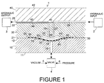
- Fig. 1 is a sectional view of a valve according to the present invention; and
- Fig. 2 is an exploded view of the valve of Fig. 1.
- Referring now to Figs. 1 and 2, the valve 1 comprises a first
rigid layer 10 having substantiallyplanar surfaces rigid layer 20 having substantiallyplanar surface rigid layer 40 having substantiallyplanar surfaces surfaces flexible layer 30 of elastomeric material such as rubber. - The valve further includes a valve chamber demarcated by a
concave surface 14 in theplanar surface 12 and by onesurface 31 of theflexible layer 30. At least onefluid passageway 15 in the firstrigid layer 10 opens into the valve chamber at theconcave surface 14 and thefluid passageway 15 is connected to avalve 4 which alternately appliesvacuum 5 orpressure 6 to the valve chamber. - The valve also includes a fluid chamber demarcated by the
surface 32 of theflexible layer 30 and a concave-convex surface in thesurface 21 comprising an innercircular convex portion 24 and a concentric annular outerconcave portion 25. - The
convex portion 24 preferably has a dome point at the center thereof and the tangent thereto is coplanar with thesurface 21 ofrigid layer 20. That dome point is aligned with the center of theconcave surface 14. -
Surface 12 also includes a compression-expansion relief annulus 13 which surrounds theconcave surface 14.Surface 21 includes a compression-expansion relief channel 23 which surrounds theannulus 13 and the concave-convex surface and defines acompression zone 33 between theannulus 13 and thechannel 23. The compression zone compresses theflexible layer 30 and thechannel 23 provides for extruded diaphragm material. When therigid layers compression zone 33 acts to seal the periphery of the valve and fluid chambers. - The
rigid layer 20 includes twofluid passageways convex portion 24 and extend to thesurface 22 thereof. - The
rigid layer 20 haschannel 44 formed in thesurface 22 thereof and therigid layer 40 haschannel 43 in the surface thereof which is aligned withchannel 44 to formfluid conduit 28.Fluid conduit 29 is formed in thesurface 41 oflayer 40. Thesurfaces passageways - Channel 29 is in communication with
passageway 27 andhydraulic input 2 andchannel 28 is in communication withpassageway 26 andhydraulic output 3. - In operation, when
vacuum 5 is applied to the valve chamber throughpassageway 15, the flexible layer flexes into position P1 so thatsurface 32 is spaced apart from theconvex portion 24 and the fluid chamber is open permitting communication between thehydraulic input 2 and thehydraulic output 3 viapassageways - When
pressure 6 is applied to the valve chamber, theflexible layer 30 flexes into the closed position P2 so that thesurface 32 is tightly against the convex andconcave surfaces hydraulic input 2 and thehydraulic output 3. - As a result of the concave-convex surface, there will be equal elastomer stretch deformation in both the open and closed positions P1 and P2.
- In one embodiment of the present invention, the rigid layers are composed of fully normalized clear cast acrylic and the flexible layer is composed of silicone sheeting. Each of the rigid layers are about 0.10" to 0.25" thick and the flexible layer is about 0.01" thick and has a diameter of about 0.375". Channel 23 has an inner diameter of 0.322" and an outer diameter of 0.4" and a height of 0.012".
Annulus 13 has a diameter of 0.225" and steps down 0.005" fromsurface 12.Compression zone 33 has an inner diameter of 0.225" and an outer diameter of 0.322" and thesurface 21 is stepped down by 0.009" in the compression zone. - Passageway 15 has a diameter of 0.031" and
passageways Concave surface 31 has a diameter of 0.156", a spherical radius of 0.1" and a depth of 0.025". Convexportion 24 has an outer diameter of 0.156", an inner diameter of 0.06" and a radius of curvature of 0.02".Concave portion 24 has a diameter of 0.06" and a spherical radius of 0.08". - It is understood that the embodiments described hereinabove are merely illustrative and are not intended to limit the scope of the invention. It is realized that various changes, alterations, rearrangements and modifications can be made by those skilled in the art without substantially departing from the spirit and scope of the present invention.
Claims (10)
- A valve comprising:
a first rigid layer having a substantially planar first surface;
a second rigid layer having a substantially planar second surface facing the first surface and a substantially planar third surface opposite the second surface;
a flexible layer positioned between the first and second surfaces;
a valve chamber demarcated by a concave surface in the substantially planar first surface and one surface of the flexible layer;
at least one first fluid passageway in the first rigid layer opening into the valve chamber at the concave surface to alternatively apply a vacuum and pressure thereto;
a fluid chamber demarcated by another surface of the flexible layer and a concave-convex surface in the substantially planar second surface and comprising an inner circular convex portion and a concentric annular outer concave portion; and
at least two second fluid passageways in the second rigid layer opening into the valve chamber at the convex surface;
whereby when a vacuum is applied to the valve chamber the flexible layer flexes to space the other surface of the flexible layer apart from the concave-convex surface to permit communication between the at least two second fluid passageways and when a pressure is applied to the valve chamber the flexible layer flexes to dispose the other surface of the flexible layer on the concave-convex surface to prevent communication between the at least two second fluid passageways. - The valve according to claim 1, wherein the concave surface in the first surface and the convex portion of the concave-convex surface have common center points.
- The valve according to claim 1, further comprising a compression-expansion relief annulus in the first substantially planar surface surrounding the concave surface and a compression-expansion relief channel in the second substantially planar surface surrounding the concave-convex surface and around the relief annulus to form a compression zone therebetween.
- The valve according to claim 3, further comprising means connecting the first and second rigid layers with the flexible layer therebetween, whereby a portion of the flexible layer in the compression zone effects a sealing of the fluid and valve chambers.
- The valve according to claim 1, further comprising a third rigid layer having a substantially planar fourth surface facing the third surface.
- The valve according to claim 5, further comprising means connecting the second and third rigid layers with the third and fourth surfaces adjacent each other.
- The valve according to claim 6, wherein the at least two second fluid passageways each comprise a channel in the third and fourth surfaces which are aligned when the second and third rigid layers are connected.
- The valve according to claim 7, wherein the means connecting the second and third rigid layers comprises means forming a seal around the channels in the third and fourth surfaces.
- The valve according to claim 8, wherein the first, second and third rigid layers comprise acrylic plastic and wherein the means forming a seal comprises means forming a diffusion bond.
- The valve according to claim 1, wherein the convex portion of the concave-convex surface has a center point which is coplanar with the first surface.
Applications Claiming Priority (2)
| Application Number | Priority Date | Filing Date | Title |
|---|---|---|---|
| US08/319,918 US5496009A (en) | 1994-10-07 | 1994-10-07 | Valve |
| US319918 | 2002-12-13 |
Publications (3)
| Publication Number | Publication Date |
|---|---|
| EP0706003A2 true EP0706003A2 (en) | 1996-04-10 |
| EP0706003A3 EP0706003A3 (en) | 1997-03-05 |
| EP0706003B1 EP0706003B1 (en) | 2000-06-07 |
Family
ID=23244146
Family Applications (1)
| Application Number | Title | Priority Date | Filing Date |
|---|---|---|---|
| EP95115676A Expired - Lifetime EP0706003B1 (en) | 1994-10-07 | 1995-10-05 | Diaphragm valve |
Country Status (9)
| Country | Link |
|---|---|
| US (1) | US5496009A (en) |
| EP (1) | EP0706003B1 (en) |
| JP (1) | JPH08210528A (en) |
| AU (1) | AU684997B2 (en) |
| CA (1) | CA2157647A1 (en) |
| DE (1) | DE69517380T2 (en) |
| ES (1) | ES2146692T3 (en) |
| IL (1) | IL115325A (en) |
| NO (1) | NO309113B1 (en) |
Cited By (4)
| Publication number | Priority date | Publication date | Assignee | Title |
|---|---|---|---|---|
| DE19913689A1 (en) * | 1999-03-25 | 2000-09-28 | Focke & Co | Device for controlling flowing media |
| US6684777B2 (en) | 2001-02-20 | 2004-02-03 | Heidelberger Druckmaschinen Ag | Device for the control of blowing air, turner bar assembly, and printing machine |
| WO2007093939A1 (en) * | 2006-02-13 | 2007-08-23 | Koninklijke Philips Electronics N.V. | Microfluidic device for molecular diagnostic applications |
| US10035148B2 (en) | 2008-07-14 | 2018-07-31 | Koninklijke Philips N.V. | Device for use in molecular diagnostics testing |
Families Citing this family (47)
| Publication number | Priority date | Publication date | Assignee | Title |
|---|---|---|---|---|
| SE501713C2 (en) * | 1993-09-06 | 1995-05-02 | Pharmacia Biosensor Ab | Diaphragm-type valve, especially for liquid handling blocks with micro-flow channels |
| IT1294948B1 (en) * | 1997-09-24 | 1999-04-23 | Giacomo Orioli | PILOTED VALVE FOR INTERCEPTION OF FLUIDS |
| US6007046A (en) * | 1997-12-15 | 1999-12-28 | Coulter International Corp. | Fluid transport circuit and valve structure therefor |
| US6196521B1 (en) | 1998-08-18 | 2001-03-06 | Precision Valve & Automation, Inc. | Fluid dispensing valve and method |
| US7144616B1 (en) * | 1999-06-28 | 2006-12-05 | California Institute Of Technology | Microfabricated elastomeric valve and pump systems |
| US6829753B2 (en) * | 2000-06-27 | 2004-12-07 | Fluidigm Corporation | Microfluidic design automation method and system |
| AU1189702A (en) * | 2000-10-13 | 2002-04-22 | Fluidigm Corp | Microfluidic device based sample injection system for analytical devices |
| AU2002212904B2 (en) * | 2000-11-02 | 2006-01-12 | Ge Healthcare Bio-Sciences Ab | Valve integrally associated with microfluidic liquid transport assembly |
| AU2002307152A1 (en) * | 2001-04-06 | 2002-10-21 | California Institute Of Technology | Nucleic acid amplification utilizing microfluidic devices |
| US8440093B1 (en) | 2001-10-26 | 2013-05-14 | Fuidigm Corporation | Methods and devices for electronic and magnetic sensing of the contents of microfluidic flow channels |
| US7691333B2 (en) * | 2001-11-30 | 2010-04-06 | Fluidigm Corporation | Microfluidic device and methods of using same |
| EP1463796B1 (en) * | 2001-11-30 | 2013-01-09 | Fluidigm Corporation | Microfluidic device and methods of using same |
| EP1499706A4 (en) | 2002-04-01 | 2010-11-03 | Fluidigm Corp | Microfluidic particle-analysis systems |
| US6637476B2 (en) | 2002-04-01 | 2003-10-28 | Protedyne Corporation | Robotically manipulable sample handling tool |
| US7312085B2 (en) * | 2002-04-01 | 2007-12-25 | Fluidigm Corporation | Microfluidic particle-analysis systems |
| US20060086309A1 (en) * | 2002-06-24 | 2006-04-27 | Fluiding Corporation | Recirculating fluidic network and methods for using the same |
| EP1551753A2 (en) | 2002-09-25 | 2005-07-13 | California Institute Of Technology | Microfluidic large scale integration |
| JP5695287B2 (en) | 2002-10-02 | 2015-04-01 | カリフォルニア インスティテュート オブ テクノロジー | Nucleic acid analysis of microfluids |
| US7249529B2 (en) * | 2003-03-28 | 2007-07-31 | Protedyne Corporation | Robotically manipulable sample handling tool |
| US20050145496A1 (en) | 2003-04-03 | 2005-07-07 | Federico Goodsaid | Thermal reaction device and method for using the same |
| US7476363B2 (en) | 2003-04-03 | 2009-01-13 | Fluidigm Corporation | Microfluidic devices and methods of using same |
| US8828663B2 (en) * | 2005-03-18 | 2014-09-09 | Fluidigm Corporation | Thermal reaction device and method for using the same |
| US7604965B2 (en) * | 2003-04-03 | 2009-10-20 | Fluidigm Corporation | Thermal reaction device and method for using the same |
| US7666361B2 (en) * | 2003-04-03 | 2010-02-23 | Fluidigm Corporation | Microfluidic devices and methods of using same |
| US7413712B2 (en) * | 2003-08-11 | 2008-08-19 | California Institute Of Technology | Microfluidic rotary flow reactor matrix |
| DE10360709A1 (en) * | 2003-12-19 | 2005-10-06 | Bartels Mikrotechnik Gmbh | Micropump and glue-free process for bonding two substrates |
| US20100171054A1 (en) * | 2006-11-28 | 2010-07-08 | Astc Aerospace Ab | Micromechanical slow acting valve system |
| US8961902B2 (en) * | 2008-04-23 | 2015-02-24 | Bioscale, Inc. | Method and apparatus for analyte processing |
| US20110229877A1 (en) | 2008-07-07 | 2011-09-22 | Oxford Nanopore Technologies Limited | Enzyme-pore constructs |
| DE102008035372A1 (en) * | 2008-07-30 | 2010-02-11 | Knorr-Bremse Systeme für Schienenfahrzeuge GmbH | Diaphragm valve, in particular for an ABS or antiskid valve |
| NZ602489A (en) * | 2010-03-19 | 2014-10-31 | Ambrosios Kambouris | Valve assembly |
| CN103370617B (en) | 2010-10-01 | 2015-11-25 | 牛津纳米孔技术有限公司 | Biochemical analysis equipment and rotary valve |
| US9618129B2 (en) * | 2010-10-07 | 2017-04-11 | Vanderbilt University | Normally closed microvalve and applications of the same |
| US20120181460A1 (en) * | 2011-01-14 | 2012-07-19 | Integenx Inc. | Valves with Hydraulic Actuation System |
| GB2492955A (en) * | 2011-07-13 | 2013-01-23 | Oxford Nanopore Tech Ltd | One way valve |
| JP5596639B2 (en) * | 2011-08-23 | 2014-09-24 | Ckd株式会社 | Dripping prevention valve |
| WO2013038164A2 (en) | 2011-09-15 | 2013-03-21 | Oxford Nanopore Technologies Limited | Piston seal |
| US20150137015A1 (en) * | 2012-07-12 | 2015-05-21 | Agency For Science, Technology And Research | Connector for microfluidic device, a method for injecting fluid into microfluidic device using the connector and a method of providing and operating a valve |
| WO2015089202A1 (en) * | 2013-12-10 | 2015-06-18 | Semba Biosciences, Inc. | High-flow fluid valve block |
| WO2015105700A1 (en) * | 2014-01-07 | 2015-07-16 | Sundew Technologies, Llc | Fluid-actuated flow control valves |
| DE102014219712B4 (en) * | 2014-09-29 | 2016-04-07 | Siemens Aktiengesellschaft | Multi-way valve |
| DE102015016265A1 (en) | 2015-12-15 | 2017-06-22 | Wabco Europe Bvba | Valve unit for pressure modulation in a compressed air brake system |
| WO2018167829A1 (en) * | 2017-03-13 | 2018-09-20 | 株式会社島津製作所 | Microvalve |
| FR3067652B1 (en) * | 2017-06-15 | 2020-09-25 | SOCIéTé BIC | FREE INK WRITING INSTRUMENT INCLUDING A MICROFLUIDIC VALVE |
| WO2019068060A1 (en) * | 2017-09-29 | 2019-04-04 | Chee Howe Shien | Bicycle saddle bag |
| EP3707414A4 (en) | 2017-11-07 | 2021-09-15 | Equilibar, LLC | Valve for single-use applications |
| JP6904267B2 (en) * | 2018-01-18 | 2021-07-14 | 株式会社島津製作所 | Valve system |
Citations (2)
| Publication number | Priority date | Publication date | Assignee | Title |
|---|---|---|---|---|
| US4852851A (en) | 1987-12-11 | 1989-08-01 | Integrated Fluidics, Inc. | Valve with flexible sheet member |
| US4875956A (en) | 1987-10-06 | 1989-10-24 | Integrated Fluidics, Inc. | Method of bonding plastics |
Family Cites Families (15)
| Publication number | Priority date | Publication date | Assignee | Title |
|---|---|---|---|---|
| US3176714A (en) * | 1961-04-11 | 1965-04-06 | Burroughs Corp | Valve assembly |
| US3312238A (en) * | 1964-12-24 | 1967-04-04 | Ibm | Monostable fluid logic element and actuator |
| DE1947533A1 (en) * | 1969-09-19 | 1971-03-25 | Messerschmitt Boelkow Blohm | Automatic shut-off valve for pressure test - equipment |
| DE2235990A1 (en) * | 1971-07-26 | 1973-02-08 | Leesona Corp | PRESSURE FLUID LOGIC ELEMENT |
| US3782682A (en) * | 1971-11-01 | 1974-01-01 | W Lale | Fluid flow controller |
| DE2648751C2 (en) * | 1976-10-27 | 1986-04-30 | Max-Planck-Gesellschaft zur Förderung der Wissenschaften e.V., 3400 Göttingen | Device for feeding liquid or gaseous substances to a processing vessel |
| US4119120A (en) * | 1976-11-29 | 1978-10-10 | Beckman Instruments, Inc. | Fluid switch |
| US4304257A (en) * | 1980-07-01 | 1981-12-08 | Instrumentation Laboratory Inc. | Valve with flexible sheet member |
| DE3209643A1 (en) * | 1982-03-17 | 1983-09-29 | Frhr. von Hardo Dr.med. 7400 Tübingen Gise | Pneumatically or hydrodynamically controlled diaphragm valve for liquid and gaseous media |
| US4703913A (en) * | 1982-09-22 | 1987-11-03 | California Institute Of Technology | Diaphragm valve |
| US4744388A (en) * | 1986-05-19 | 1988-05-17 | Fujikura Rubber Ltd. | Diaphragm type of pilot operated directional control valve |
| US4723131A (en) * | 1986-09-12 | 1988-02-02 | Diagraph Corporation | Printhead for ink jet printing apparatus |
| US4848722A (en) * | 1987-12-11 | 1989-07-18 | Integrated Fluidics, Inc. | Valve with flexible sheet member |
| US4858883A (en) * | 1987-12-11 | 1989-08-22 | Integrated Fluidics, Inc. | Valve with flexible sheet member |
| FR2664671B1 (en) * | 1990-07-12 | 1992-10-09 | Centre Nat Rech Scient | MULTIWAY VALVE AND DEVICE, PARTICULARLY FOR CORROSIVE FLUIDS. |
-
1994
- 1994-10-07 US US08/319,918 patent/US5496009A/en not_active Expired - Lifetime
-
1995
- 1995-09-06 CA CA002157647A patent/CA2157647A1/en not_active Abandoned
- 1995-09-15 IL IL11532595A patent/IL115325A/en active IP Right Grant
- 1995-09-27 AU AU32926/95A patent/AU684997B2/en not_active Ceased
- 1995-10-04 JP JP7279923A patent/JPH08210528A/en active Pending
- 1995-10-05 EP EP95115676A patent/EP0706003B1/en not_active Expired - Lifetime
- 1995-10-05 DE DE69517380T patent/DE69517380T2/en not_active Expired - Fee Related
- 1995-10-05 ES ES95115676T patent/ES2146692T3/en not_active Expired - Lifetime
- 1995-10-06 NO NO953981A patent/NO309113B1/en not_active IP Right Cessation
Patent Citations (2)
| Publication number | Priority date | Publication date | Assignee | Title |
|---|---|---|---|---|
| US4875956A (en) | 1987-10-06 | 1989-10-24 | Integrated Fluidics, Inc. | Method of bonding plastics |
| US4852851A (en) | 1987-12-11 | 1989-08-01 | Integrated Fluidics, Inc. | Valve with flexible sheet member |
Cited By (6)
| Publication number | Priority date | Publication date | Assignee | Title |
|---|---|---|---|---|
| DE19913689A1 (en) * | 1999-03-25 | 2000-09-28 | Focke & Co | Device for controlling flowing media |
| US6554026B1 (en) | 1999-03-25 | 2003-04-29 | Focke & Co. (Gmbh & Co.) | Device for controlling flowing media |
| US6684777B2 (en) | 2001-02-20 | 2004-02-03 | Heidelberger Druckmaschinen Ag | Device for the control of blowing air, turner bar assembly, and printing machine |
| WO2007093939A1 (en) * | 2006-02-13 | 2007-08-23 | Koninklijke Philips Electronics N.V. | Microfluidic device for molecular diagnostic applications |
| US10035148B2 (en) | 2008-07-14 | 2018-07-31 | Koninklijke Philips N.V. | Device for use in molecular diagnostics testing |
| US10343169B2 (en) | 2008-07-14 | 2019-07-09 | Koninklijke Philips N.V. | Device for use in molecular diagnostics testing |
Also Published As
| Publication number | Publication date |
|---|---|
| AU684997B2 (en) | 1998-01-08 |
| DE69517380T2 (en) | 2000-10-12 |
| IL115325A0 (en) | 1995-12-31 |
| ES2146692T3 (en) | 2000-08-16 |
| JPH08210528A (en) | 1996-08-20 |
| IL115325A (en) | 1998-12-27 |
| NO309113B1 (en) | 2000-12-11 |
| DE69517380D1 (en) | 2000-07-13 |
| NO953981L (en) | 1996-04-09 |
| EP0706003B1 (en) | 2000-06-07 |
| AU3292695A (en) | 1996-04-18 |
| US5496009A (en) | 1996-03-05 |
| EP0706003A3 (en) | 1997-03-05 |
| NO953981D0 (en) | 1995-10-06 |
| CA2157647A1 (en) | 1996-04-08 |
Similar Documents
| Publication | Publication Date | Title |
|---|---|---|
| EP0706003B1 (en) | Diaphragm valve | |
| EP0706004A2 (en) | Relief valve | |
| US5902096A (en) | Diaphragm pump having multiple rigid layers with inlet and outlet check valves | |
| US4858883A (en) | Valve with flexible sheet member | |
| US4852851A (en) | Valve with flexible sheet member | |
| US4848722A (en) | Valve with flexible sheet member | |
| US5213485A (en) | Air driven double diaphragm pump | |
| US5169296A (en) | Air driven double diaphragm pump | |
| CN102812276B (en) | Microvalve | |
| EP1030989B1 (en) | Diaphragm valve for a fluid circuit | |
| US7779867B2 (en) | Miniature valve | |
| US3856046A (en) | Valve | |
| US4523610A (en) | Check valve | |
| US5025828A (en) | Valve assembly for a piston compressor | |
| WO1995014874A1 (en) | Self-biasing diaphragm in a valve | |
| JPH11257533A (en) | Solenoid valve | |
| US20200239214A1 (en) | Pressure relief valve with floating diaphragm | |
| JPH03223580A (en) | Piezoelectric type valve device | |
| JPS6078175A (en) | Four-way selector valve | |
| JPH0743443Y2 (en) | accumulator | |
| JPH07229579A (en) | Microvalve device | |
| JPH04160279A (en) | Diaphragm valve | |
| AU1724399A (en) | Ferroelectric fluid flow control valve | |
| EP0513268A1 (en) | Diaphragm valve | |
| JPS5899507A (en) | Valve apparatus |
Legal Events
| Date | Code | Title | Description |
|---|---|---|---|
| PUAI | Public reference made under article 153(3) epc to a published international application that has entered the european phase |
Free format text: ORIGINAL CODE: 0009012 |
|
| AK | Designated contracting states |
Kind code of ref document: A2 Designated state(s): BE CH DE DK ES FR GB IT LI NL SE |
|
| PUAL | Search report despatched |
Free format text: ORIGINAL CODE: 0009013 |
|
| AK | Designated contracting states |
Kind code of ref document: A3 Designated state(s): BE CH DE DK ES FR GB IT LI NL SE |
|
| RAP1 | Party data changed (applicant data changed or rights of an application transferred) |
Owner name: BAYER CORPORATION |
|
| 17P | Request for examination filed |
Effective date: 19970905 |
|
| GRAG | Despatch of communication of intention to grant |
Free format text: ORIGINAL CODE: EPIDOS AGRA |
|
| 17Q | First examination report despatched |
Effective date: 19990723 |
|
| GRAG | Despatch of communication of intention to grant |
Free format text: ORIGINAL CODE: EPIDOS AGRA |
|
| GRAH | Despatch of communication of intention to grant a patent |
Free format text: ORIGINAL CODE: EPIDOS IGRA |
|
| GRAH | Despatch of communication of intention to grant a patent |
Free format text: ORIGINAL CODE: EPIDOS IGRA |
|
| GRAA | (expected) grant |
Free format text: ORIGINAL CODE: 0009210 |
|
| AK | Designated contracting states |
Kind code of ref document: B1 Designated state(s): BE CH DE DK ES FR GB IT LI NL SE |
|
| PG25 | Lapsed in a contracting state [announced via postgrant information from national office to epo] |
Ref country code: NL Free format text: LAPSE BECAUSE OF FAILURE TO SUBMIT A TRANSLATION OF THE DESCRIPTION OR TO PAY THE FEE WITHIN THE PRESCRIBED TIME-LIMIT Effective date: 20000607 Ref country code: LI Free format text: LAPSE BECAUSE OF FAILURE TO SUBMIT A TRANSLATION OF THE DESCRIPTION OR TO PAY THE FEE WITHIN THE PRESCRIBED TIME-LIMIT Effective date: 20000607 Ref country code: CH Free format text: LAPSE BECAUSE OF FAILURE TO SUBMIT A TRANSLATION OF THE DESCRIPTION OR TO PAY THE FEE WITHIN THE PRESCRIBED TIME-LIMIT Effective date: 20000607 Ref country code: BE Free format text: LAPSE BECAUSE OF FAILURE TO SUBMIT A TRANSLATION OF THE DESCRIPTION OR TO PAY THE FEE WITHIN THE PRESCRIBED TIME-LIMIT Effective date: 20000607 |
|
| REG | Reference to a national code |
Ref country code: CH Ref legal event code: EP |
|
| REF | Corresponds to: |
Ref document number: 69517380 Country of ref document: DE Date of ref document: 20000713 |
|
| ET | Fr: translation filed | ||
| ITF | It: translation for a ep patent filed |
Owner name: ING. C. GREGORJ S.P.A. |
|
| REG | Reference to a national code |
Ref country code: ES Ref legal event code: FG2A Ref document number: 2146692 Country of ref document: ES Kind code of ref document: T3 |
|
| PG25 | Lapsed in a contracting state [announced via postgrant information from national office to epo] |
Ref country code: DK Free format text: LAPSE BECAUSE OF FAILURE TO SUBMIT A TRANSLATION OF THE DESCRIPTION OR TO PAY THE FEE WITHIN THE PRESCRIBED TIME-LIMIT Effective date: 20000907 |
|
| NLV1 | Nl: lapsed or annulled due to failure to fulfill the requirements of art. 29p and 29m of the patents act | ||
| REG | Reference to a national code |
Ref country code: CH Ref legal event code: PL |
|
| PLBE | No opposition filed within time limit |
Free format text: ORIGINAL CODE: 0009261 |
|
| STAA | Information on the status of an ep patent application or granted ep patent |
Free format text: STATUS: NO OPPOSITION FILED WITHIN TIME LIMIT |
|
| 26N | No opposition filed | ||
| PGFP | Annual fee paid to national office [announced via postgrant information from national office to epo] |
Ref country code: ES Payment date: 20011108 Year of fee payment: 7 |
|
| REG | Reference to a national code |
Ref country code: GB Ref legal event code: IF02 |
|
| PGFP | Annual fee paid to national office [announced via postgrant information from national office to epo] |
Ref country code: SE Payment date: 20020919 Year of fee payment: 8 |
|
| PG25 | Lapsed in a contracting state [announced via postgrant information from national office to epo] |
Ref country code: ES Free format text: LAPSE BECAUSE OF NON-PAYMENT OF DUE FEES Effective date: 20021006 |
|
| PG25 | Lapsed in a contracting state [announced via postgrant information from national office to epo] |
Ref country code: SE Free format text: LAPSE BECAUSE OF NON-PAYMENT OF DUE FEES Effective date: 20031006 |
|
| REG | Reference to a national code |
Ref country code: ES Ref legal event code: FD2A Effective date: 20031112 |
|
| EUG | Se: european patent has lapsed | ||
| PG25 | Lapsed in a contracting state [announced via postgrant information from national office to epo] |
Ref country code: IT Free format text: LAPSE BECAUSE OF NON-PAYMENT OF DUE FEES Effective date: 20051005 |
|
| PGFP | Annual fee paid to national office [announced via postgrant information from national office to epo] |
Ref country code: GB Payment date: 20061025 Year of fee payment: 12 |
|
| PGFP | Annual fee paid to national office [announced via postgrant information from national office to epo] |
Ref country code: DE Payment date: 20061130 Year of fee payment: 12 |
|
| GBPC | Gb: european patent ceased through non-payment of renewal fee |
Effective date: 20071005 |
|
| PG25 | Lapsed in a contracting state [announced via postgrant information from national office to epo] |
Ref country code: DE Free format text: LAPSE BECAUSE OF NON-PAYMENT OF DUE FEES Effective date: 20080501 |
|
| PG25 | Lapsed in a contracting state [announced via postgrant information from national office to epo] |
Ref country code: GB Free format text: LAPSE BECAUSE OF NON-PAYMENT OF DUE FEES Effective date: 20071005 |
|
| PGFP | Annual fee paid to national office [announced via postgrant information from national office to epo] |
Ref country code: FR Payment date: 20121031 Year of fee payment: 18 |
|
| REG | Reference to a national code |
Ref country code: FR Ref legal event code: ST Effective date: 20140630 |
|
| PG25 | Lapsed in a contracting state [announced via postgrant information from national office to epo] |
Ref country code: FR Free format text: LAPSE BECAUSE OF NON-PAYMENT OF DUE FEES Effective date: 20131031 |