EP0714203A2 - Video display system with digital processingM - Google Patents
Video display system with digital processingM Download PDFInfo
- Publication number
- EP0714203A2 EP0714203A2 EP95118461A EP95118461A EP0714203A2 EP 0714203 A2 EP0714203 A2 EP 0714203A2 EP 95118461 A EP95118461 A EP 95118461A EP 95118461 A EP95118461 A EP 95118461A EP 0714203 A2 EP0714203 A2 EP 0714203A2
- Authority
- EP
- European Patent Office
- Prior art keywords
- video
- sources
- video data
- data
- digital
- Prior art date
- Legal status (The legal status is an assumption and is not a legal conclusion. Google has not performed a legal analysis and makes no representation as to the accuracy of the status listed.)
- Withdrawn
Links
- 230000000750 progressive effect Effects 0.000 claims abstract description 9
- 230000001360 synchronised effect Effects 0.000 claims 1
- 230000006870 function Effects 0.000 description 4
- 238000006243 chemical reaction Methods 0.000 description 3
- 239000002131 composite material Substances 0.000 description 2
- 238000010586 diagram Methods 0.000 description 2
- 230000005540 biological transmission Effects 0.000 description 1
- 238000003708 edge detection Methods 0.000 description 1
- 230000000694 effects Effects 0.000 description 1
- 238000003702 image correction Methods 0.000 description 1
- 239000004973 liquid crystal related substance Substances 0.000 description 1
- 238000000034 method Methods 0.000 description 1
Images

Classifications
-
- H—ELECTRICITY
- H04—ELECTRIC COMMUNICATION TECHNIQUE
- H04N—PICTORIAL COMMUNICATION, e.g. TELEVISION
- H04N5/00—Details of television systems
- H04N5/44—Receiver circuitry for the reception of television signals according to analogue transmission standards
- H04N5/445—Receiver circuitry for the reception of television signals according to analogue transmission standards for displaying additional information
- H04N5/45—Picture in picture, e.g. displaying simultaneously another television channel in a region of the screen
-
- H—ELECTRICITY
- H04—ELECTRIC COMMUNICATION TECHNIQUE
- H04N—PICTORIAL COMMUNICATION, e.g. TELEVISION
- H04N7/00—Television systems
- H04N7/01—Conversion of standards, e.g. involving analogue television standards or digital television standards processed at pixel level
- H04N7/0117—Conversion of standards, e.g. involving analogue television standards or digital television standards processed at pixel level involving conversion of the spatial resolution of the incoming video signal
- H04N7/012—Conversion between an interlaced and a progressive signal
Definitions
- This invention relates to digital television systems, more particularly to special features for digital television systems.
- Digital television has several advantages over the current standard analog system. Because the digital data can be packed, more data can be transmitted that allows for a better picture. Additionally, manipulation of the data on a picture element (pixel) level can reduce artifacts and increase the resolution and overall clarity of the picture.
- pixel picture element
- PIP picture-in-picture
- Picture-outside-picture typically has the extra channels along the side, top or bottom of the main channel, but instead of encroaching on the main channel's picture, they are boxed next to it.
- Additional special features are zoom, freeze, TV guide and his/hers.
- TV guide usually involves some number of channels all displayed simultaneously, with no main channel picture, so the viewer can decide what to watch. His/hers includes two pictures, side by side on the TV.
- a digital implementation of a television system with special features is disclosed.
- the ability to perform these functions digitally allows the system to function entirely in the digital realm after reception of the signal. If the signal received is analog, it is converted once to the digital domain and processed digitally all the way through the system. Performing these special functions in the digital domain also has the advantage of eliminating conversion to analog then back to digital if the incoming signal is digital. Addition of a switch allows all of these features to be provided with no redundant circuitry and therefore at minimum cost.
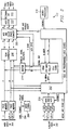
- Figure 1 shows a digital display system with a special features module.
- the incoming video could be in several formats. It could come in through a receiver such as 102 and enter the switch 106 as a composite video signal.
- Lines 104 represent input in S-Video format, where the chrominance and luminance have been separated into channels. All channels receivable by the television set, either in composite or in S-Video format, will be received at switch 106.
- the feature select line 116 represents the viewers' input.
- the main channel data will travel to the special features box through the chrominance and luminance switch (Y/C switch) 120 onto path 108 and the auxiliary video on path 110.
- the auxiliary channel could be handled in ways separate from the way in which the main channel is handled. However, for ease of discussion they are both processed the same way in Figure 1. Which channels comprise the auxiliary video depends upon the feature select signal 116 which is passed to the special features module 112 along path 118. For example, if the viewer wanted to watch channel 8 and have 2 picture-in-picture (PIP) displays of channels 4 and 6, the main channel data would be channel 8 and the selected, or predetermined, auxiliary channel data would be two channels wide with channels 4 and 6. The number of channels selectable is only limited by the amount of memory in the system. Additionally, all of the elements within box 100 could be on one device.
- PIP picture-in-picture
- Special features created by the special features circuitry include PIP, picture out of picture (POP), zoom, freeze, his/hers, and TV guide.
- PIP features has a main channel picture of moving video, with a smaller picture of moving video within the borders of the main picture. More than one smaller picture could be displayed. For circuitry conservation, the additional pictures may not be moving video, but "frozen" where one frame of data is displayed without change.
- POP differs from PIP in that the main channel picture remains uncovered by the smaller pictures.
- the two channels are reproduced side by side on the same screen. Zoom enlarges a portion of the picture to fill the entire display area. Freeze pauses the main video picture. Finally, TV guide allows the viewer to simultaneously display several channels of TV in order to select the one which is to be watched.
- ASIC application specific integrated circuit
- programmable logic device 212 programmable logic device 212 that will create the special features.
- the special feature data must be inserted in the appropriate place in the progressively scanned picture. Eventually, this adjusted data will be returned to the main video data stream just before it enters the scan converter 216, which actually performs the interlace to progressive scan conversion.
- Joining the signals from the main video channel are the signals from the auxiliary video channel.
- the luminance and color difference signals are low-pass filtered to eliminate any high frequency noise and sent to a multiplexer and analog to digital converter (MUX & A/D) 210. If the incoming data is digital television, the use of the A/D is no longer necessary.
- MUX & A/D analog to digital converter
- the ASIC or programmable logic device 212 also receives a horizontal and vertical synchronization signal from the main channel and the auxiliary channel. It decodes these signals and coordinates the flow of data from each channel accordingly. It also decodes the auxiliary channel synchronization signals to generate the multiplexer select and sample clock of the MUX & A/D 210.
- the ASIC 212 creates the appropriate feature to the correct scale under control of microprocessor 218.
- the feature data is processed it is sent via a 16-bit DRAM bus to a VRAM 226. At the appropriate time, the data then passes to buffer 214, or in the case of PIP/POP data, directly to MUX and color space converter 220.
- the ASIC 212 generates the necessary VRAM read and write addresses and control signals to implement the desired feature. For certain features, such as PIP/POP, the ASIC 212 also converts the auxiliary channel's interlaced data to progressive scan data for mixing into the main video channel's stream. Other features may utilize the scan converter 216 via the buffer 214.
- the color space converter inserts the PIP/POP data into the appropriate part of the picture data and converts the entire frame into red-green-blue (RGB) data. This RGB data is then sent to a data latch 222. Finally, if the signal contains gamma correction, the gamma must be removed via a degamma lookup table (LUT) 224 and the proscan video output is sent to the array.
- LUT degamma lookup table
- the resultant image has the appropriate feature, as selected by the viewer, in the overall picture, typically sent to the display device as one data stream.
- the digital processing of these features will become important if the incoming data stream is digital, rather than the analog standards currently used.
- using a digital means of display such as the DMD and LCD light modulators in conjunction with a digital special features implementation allows for better coordination and image correction by allowing additional processing of the data before it moves to the array to reduce other artifacts not necessarily related to the processing of special features. This includes such elements as motion and edge detection to eliminate other processing artifacts, or to enhance color and contrast.
Abstract
Description
- This invention relates to digital television systems, more particularly to special features for digital television systems.
- Digital television has several advantages over the current standard analog system. Because the digital data can be packed, more data can be transmitted that allows for a better picture. Additionally, manipulation of the data on a picture element (pixel) level can reduce artifacts and increase the resolution and overall clarity of the picture.
- Currently, most televisions that implement digital displays remain restricted by the analog transmission standard. Because of that and because, to some extent, adding special features in analog requires less data manipulation, most of these sets do all of the processing in the analog realm and convert to digital just before display.
- While some special feature processing modules process data in the digital realm internally, most have analog input and output (I/O) to support analog broadcast and display standards. These processing modules must then include an analog to digital (A/D) converter for the inputs and a digital to analog (D/A) converter for the outputs. This increases the complexity and cost of the processing circuitry over a circuit with digital I/O. Further, each converter degrades the digital signal. For televisions that implement digital displays and several special feature modules, this series of A/Ds and D/As can noticeably corrupt the television picture.
- Special features include picture-in-picture (PIP), which allows other channels to be viewed within the main channel's picture. These usually reside in small windows around the outside of the main channel's picture, or the channel being viewed. Picture-outside-picture typically has the extra channels along the side, top or bottom of the main channel, but instead of encroaching on the main channel's picture, they are boxed next to it. Additional special features are zoom, freeze, TV guide and his/hers.
- TV guide usually involves some number of channels all displayed simultaneously, with no main channel picture, so the viewer can decide what to watch. His/hers includes two pictures, side by side on the TV.
- Most current television systems perform the channel manipulation and set up in analog and then convert the incoming data to digital format for display. This becomes awkward when either the entire television system functions digitally, or the incoming signal is itself digital. Therefore, a need exists for the ability to provide the special features of a television set in the digital realm.
- A digital implementation of a television system with special features is disclosed. The ability to perform these functions digitally allows the system to function entirely in the digital realm after reception of the signal. If the signal received is analog, it is converted once to the digital domain and processed digitally all the way through the system. Performing these special functions in the digital domain also has the advantage of eliminating conversion to analog then back to digital if the incoming signal is digital. Addition of a switch allows all of these features to be provided with no redundant circuitry and therefore at minimum cost.
- For a more complete understanding of the present invention and for further advantages thereof, reference is now made to the following Detailed Description taken in conjunction with the accompanying Drawings in which:
- Figure 1 shows a system level diagram of a digital television system; and
- Figure 2 shows a schematic diagram of the special features processor of a digital television system.
- Figure 1 shows a digital display system with a special features module. The incoming video could be in several formats. It could come in through a receiver such as 102 and enter the
switch 106 as a composite video signal.Lines 104 represent input in S-Video format, where the chrominance and luminance have been separated into channels. All channels receivable by the television set, either in composite or in S-Video format, will be received atswitch 106. The featureselect line 116 represents the viewers' input. - For whatever feature the viewer selects, the main channel data will travel to the special features box through the chrominance and luminance switch (Y/C switch) 120 onto
path 108 and the auxiliary video onpath 110. The auxiliary channel could be handled in ways separate from the way in which the main channel is handled. However, for ease of discussion they are both processed the same way in Figure 1. Which channels comprise the auxiliary video depends upon the featureselect signal 116 which is passed to thespecial features module 112 alongpath 118. For example, if the viewer wanted to watchchannel 8 and have 2 picture-in-picture (PIP) displays ofchannels 4 and 6, the main channel data would bechannel 8 and the selected, or predetermined, auxiliary channel data would be two channels wide withchannels 4 and 6. The number of channels selectable is only limited by the amount of memory in the system. Additionally, all of the elements withinbox 100 could be on one device. - Special features created by the special features circuitry include PIP, picture out of picture (POP), zoom, freeze, his/hers, and TV guide. The PIP features has a main channel picture of moving video, with a smaller picture of moving video within the borders of the main picture. More than one smaller picture could be displayed. For circuitry conservation, the additional pictures may not be moving video, but "frozen" where one frame of data is displayed without change. POP differs from PIP in that the main channel picture remains uncovered by the smaller pictures.
- In his/her format, the two channels are reproduced side by side on the same screen. Zoom enlarges a portion of the picture to fill the entire display area. Freeze pauses the main video picture. Finally, TV guide allows the viewer to simultaneously display several channels of TV in order to select the one which is to be watched.
- All of these features are enabled in digital format by the
special features module 112 in Figure 2. Starting with themain video lines 204, adjustment must first be made for the interlaced nature of most broadcast video. Broadcast video typically comes in a format that requires two fields to be interlaced together. One field typically contains the odd-numbered lines and the other field contains the even-numbered lines. The fields are put together on a cathode ray tube type display. Some examples of digital type displays are digital micromirror device (DMD) displays, and liquid crystal device (LCD displays). Additionally an A/D converter, not shown, is necessary for analog digital input. - These types of displays use an array of individually addressable cells that are typically addressed by rows and columns. Because of the nature of this addressing, it is impractical to interlace the fields as in the CRT applications. The entire frame must be recreated on the face of the device before it is transmitted to the screen, referred to in this context as progressive scan. In order to compensate for this interlacing effect, the luminance signal Y is sent to a field memory and the chrominance difference signals U/R-Y and V/B-Y are sent to a field memory. This allows storage of the data needed to convert the signal from interlace to progressive scan. Conversion of the interlaced signal to progressive scan is also discussed in Published European Patent document 0,651,577.
- These three signals are also sent to an application specific integrated circuit (ASIC) or
programmable logic device 212 that will create the special features. The special feature data must be inserted in the appropriate place in the progressively scanned picture. Eventually, this adjusted data will be returned to the main video data stream just before it enters thescan converter 216, which actually performs the interlace to progressive scan conversion. - Joining the signals from the main video channel are the signals from the auxiliary video channel. The luminance and color difference signals are low-pass filtered to eliminate any high frequency noise and sent to a multiplexer and analog to digital converter (MUX & A/D) 210. If the incoming data is digital television, the use of the A/D is no longer necessary.
- The ASIC or
programmable logic device 212 also receives a horizontal and vertical synchronization signal from the main channel and the auxiliary channel. It decodes these signals and coordinates the flow of data from each channel accordingly. It also decodes the auxiliary channel synchronization signals to generate the multiplexer select and sample clock of the MUX & A/D 210. TheASIC 212 creates the appropriate feature to the correct scale under control ofmicroprocessor 218. When the feature data is processed it is sent via a 16-bit DRAM bus to a VRAM 226. At the appropriate time, the data then passes to buffer 214, or in the case of PIP/POP data, directly to MUX andcolor space converter 220. TheASIC 212 generates the necessary VRAM read and write addresses and control signals to implement the desired feature. For certain features, such as PIP/POP, theASIC 212 also converts the auxiliary channel's interlaced data to progressive scan data for mixing into the main video channel's stream. Other features may utilize thescan converter 216 via thebuffer 214. - The color space converter inserts the PIP/POP data into the appropriate part of the picture data and converts the entire frame into red-green-blue (RGB) data. This RGB data is then sent to a
data latch 222. Finally, if the signal contains gamma correction, the gamma must be removed via a degamma lookup table (LUT) 224 and the proscan video output is sent to the array. - The resultant image has the appropriate feature, as selected by the viewer, in the overall picture, typically sent to the display device as one data stream. The digital processing of these features will become important if the incoming data stream is digital, rather than the analog standards currently used. Additionally, using a digital means of display such as the DMD and LCD light modulators in conjunction with a digital special features implementation allows for better coordination and image correction by allowing additional processing of the data before it moves to the array to reduce other artifacts not necessarily related to the processing of special features. This includes such elements as motion and edge detection to eliminate other processing artifacts, or to enhance color and contrast.
Claims (14)
- A video display system, comprising:
multiple video input sources;
a switch for selecting at least two sources from said multiple input sources;
circuitry for digitally multiplexing said at least two sources into one stream of video data;
a display for displaying said digitally multiplexed video data. - The system of Claim 1, wherein said circuitry comprises;
a special feature module. - The system of claims 1-2, wherein said multiple input video sources include both analog and digital sources, said analog sources being digitized for use in said system.
- The system of claims 1-2, wherein said multiple input video sources include only analog sources, said analog sources being digitized for use in said system.
- The system of claims 1-4, wherein said special feature module includes an application specific integrated circuit for processing one of said at least two sources as an auxiliary input source.
- The system of claims 1-5, wherein said special feature module includes a scan converter for mixing said at least two sources into one digital output stream of video data.
- The system of Claims 1-6, further comprising:
a switch for receiving incoming video signals and a feature selection signal. - The system of Claims 1-7, further comprising:
a main video channel for displaying;
video data received from a predetermined one of said sources. - The system of Claim 8, further comprising:
an auxiliary video channel for displaying video data from at least one alternate predetermined source. - The system of Claims 8-9, further comprising:
a scan converter for converting said incoming video data from an interlaced format to video data comprising progressive scan video images. - The system of Claims 8-10, further comprising:
a logic device for mixing video data from said at least one alternate predetermined source with video data from said main channel data. - The system of Claims 8-11, further comprising:
a master synchronization circuit for coordinating timing of said video data such that said video data is synchronous with said progressive scan video image. - The system of claims 11-12, wherein said logic device incorporates video data from said at least one alternate predetermined source into said progressive scan video images.
- The system of claims 11-13, wherein said logic device is operable to provide video data from said at least one alternate predetermined source to said scan converter.
Applications Claiming Priority (2)
| Application Number | Priority Date | Filing Date | Title |
|---|---|---|---|
| US34425694A | 1994-11-23 | 1994-11-23 | |
| US344256 | 1994-11-23 |
Publications (2)
| Publication Number | Publication Date |
|---|---|
| EP0714203A2 true EP0714203A2 (en) | 1996-05-29 |
| EP0714203A3 EP0714203A3 (en) | 1998-04-08 |
Family
ID=23349723
Family Applications (1)
| Application Number | Title | Priority Date | Filing Date |
|---|---|---|---|
| EP95118461A Withdrawn EP0714203A3 (en) | 1994-11-23 | 1995-11-23 | Video display system with digital processingM |
Country Status (5)
| Country | Link |
|---|---|
| US (1) | US5999227A (en) |
| EP (1) | EP0714203A3 (en) |
| JP (1) | JPH08251504A (en) |
| KR (1) | KR960020415A (en) |
| TW (1) | TW441213B (en) |
Cited By (1)
| Publication number | Priority date | Publication date | Assignee | Title |
|---|---|---|---|---|
| EP1024663A2 (en) * | 1999-01-29 | 2000-08-02 | Canon Kabushiki Kaisha | Image processing device |
Families Citing this family (12)
| Publication number | Priority date | Publication date | Assignee | Title |
|---|---|---|---|---|
| KR100206114B1 (en) * | 1996-10-11 | 1999-07-01 | 윤종용 | Advanced video line connector |
| DE69738816D1 (en) * | 1996-10-28 | 2008-08-21 | Texas Instruments Inc | Improvements to image display systems |
| JP3360586B2 (en) * | 1997-11-21 | 2002-12-24 | 日本電気株式会社 | Scan conversion apparatus and method |
| CA2312562C (en) | 1998-10-01 | 2006-07-25 | Matsushita Electric Industrial Co., Ltd. | Image signal conversion equipment |
| US6971118B1 (en) * | 1999-07-28 | 2005-11-29 | Sharp Laboratories Of America, Inc. | System for displaying programming guide information |
| JP3998399B2 (en) * | 1999-12-03 | 2007-10-24 | 松下電器産業株式会社 | Video signal converter |
| KR100441504B1 (en) * | 2002-01-15 | 2004-07-23 | 삼성전자주식회사 | Image Signal Recovering Apparatus having a function each analog to digital converting composite and component signal of main picture and sub picture |
| KR100586669B1 (en) * | 2003-08-27 | 2006-06-08 | 닛뽕빅터 가부시키가이샤 | Transmission system |
| GB0419870D0 (en) * | 2004-09-08 | 2004-10-13 | Koninkl Philips Electronics Nv | Apparatus and method for processing video data |
| KR100716771B1 (en) * | 2005-07-14 | 2007-05-14 | 삼성전자주식회사 | Display apparatus and control method thereof |
| US8947297B2 (en) * | 2006-01-30 | 2015-02-03 | The Invention Science Fund I, Llc | Positional display elements |
| EP2416565A1 (en) * | 2010-08-05 | 2012-02-08 | Thomson Licensing | Method for handling of audio/video signals and corresponding device |
Citations (1)
| Publication number | Priority date | Publication date | Assignee | Title |
|---|---|---|---|---|
| EP0651577A2 (en) | 1993-10-27 | 1995-05-03 | Texas Instruments Incorporated | Digital television system |
Family Cites Families (17)
| Publication number | Priority date | Publication date | Assignee | Title |
|---|---|---|---|---|
| US4712130A (en) * | 1986-08-29 | 1987-12-08 | Rca Corporation | Chrominance signal frequency converter as for a pix-in-pix television receiver |
| US4743958A (en) * | 1986-10-06 | 1988-05-10 | The Grass Valley Group, Inc. | Multiple television standards input selector and convertor |
| US4809069A (en) * | 1988-03-10 | 1989-02-28 | North American Philips Corporation | Multifunction memory for digital television |
| US5250933A (en) * | 1989-03-02 | 1993-10-05 | Hewlett-Packard Company | Method and apparatus for the simultaneous display of one or more selected images |
| US5134484A (en) * | 1989-06-01 | 1992-07-28 | Mindseye Educational Systems, Inc. | Superimposing method and apparatus useful for subliminal messages |
| US5367334A (en) * | 1991-05-20 | 1994-11-22 | Matsushita Electric Industrial Co., Ltd. | Video signal encoding and decoding apparatus |
| JPH04365278A (en) * | 1991-06-13 | 1992-12-17 | Matsushita Electric Ind Co Ltd | Multi-screen display circuit |
| EP0523299A1 (en) * | 1991-07-18 | 1993-01-20 | International Business Machines Corporation | System and method for combining multiple composite video signals |
| KR950000828B1 (en) * | 1991-12-11 | 1995-02-02 | 삼성전자 주식회사 | Multi-function tv |
| US5157495A (en) * | 1991-12-20 | 1992-10-20 | Eastman Kodak Company | Multi-mode video standard selection circuit and selection method |
| JPH05183833A (en) * | 1992-01-07 | 1993-07-23 | Sony Corp | Display device |
| US5351129A (en) * | 1992-03-24 | 1994-09-27 | Rgb Technology D/B/A Rgb Spectrum | Video multiplexor-encoder and decoder-converter |
| US5347318A (en) * | 1992-06-16 | 1994-09-13 | Canon Kabushiki Kaisha | Apparatus for processing video signals having different aspect ratios |
| US5331417A (en) * | 1992-09-15 | 1994-07-19 | Digital Pictures, Inc. | System and method of displaying a plurality of digital video images |
| JPH06189345A (en) * | 1992-12-22 | 1994-07-08 | Matsushita Electric Ind Co Ltd | Hdtv signal transmitter |
| US5420534A (en) * | 1993-10-27 | 1995-05-30 | Loral Fairchild Corporation | Programmable NxM switching system with charge-coupled device multiplexer |
| US5453796A (en) * | 1994-06-28 | 1995-09-26 | Thomson Consumer Electronics, Inc. | Signal swap apparatus for a television receiver having an HDTV main picture signal processor and an NTSC Pix-in-Pix signal processor |
-
1995
- 1995-11-22 KR KR1019950042834A patent/KR960020415A/en not_active Application Discontinuation
- 1995-11-23 EP EP95118461A patent/EP0714203A3/en not_active Withdrawn
- 1995-11-24 JP JP7305828A patent/JPH08251504A/en active Pending
-
1996
- 1996-01-05 TW TW085100071A patent/TW441213B/en not_active IP Right Cessation
-
1997
- 1997-06-13 US US08/876,112 patent/US5999227A/en not_active Expired - Lifetime
Patent Citations (1)
| Publication number | Priority date | Publication date | Assignee | Title |
|---|---|---|---|---|
| EP0651577A2 (en) | 1993-10-27 | 1995-05-03 | Texas Instruments Incorporated | Digital television system |
Cited By (4)
| Publication number | Priority date | Publication date | Assignee | Title |
|---|---|---|---|---|
| EP1024663A2 (en) * | 1999-01-29 | 2000-08-02 | Canon Kabushiki Kaisha | Image processing device |
| EP1024663A3 (en) * | 1999-01-29 | 2003-07-23 | Canon Kabushiki Kaisha | Image processing device |
| US6831634B1 (en) | 1999-01-29 | 2004-12-14 | Canon Kabushiki Kaisha | Image processing device |
| US7079129B2 (en) | 1999-01-29 | 2006-07-18 | Canon Kabushiki Kaisha | Image processing device |
Also Published As
| Publication number | Publication date |
|---|---|
| JPH08251504A (en) | 1996-09-27 |
| TW441213B (en) | 2001-06-16 |
| KR960020415A (en) | 1996-06-17 |
| US5999227A (en) | 1999-12-07 |
| EP0714203A3 (en) | 1998-04-08 |
Similar Documents
| Publication | Publication Date | Title |
|---|---|---|
| US5796442A (en) | Multi-format television reciever | |
| US6421094B1 (en) | HDTV video display processor | |
| EP0766470B1 (en) | Television receiver for teletext | |
| KR100256443B1 (en) | Multimedia display device | |
| US20100277645A1 (en) | Video apparatus and image sensing apparatus | |
| KR100186409B1 (en) | Circuit for processing pip image signal suitable type in the tv and pc | |
| CA2241457A1 (en) | High definition television for simultaneously displaying plural images contained in broadcasting signals of mutually different broadcasting systems | |
| US5999227A (en) | Special features for digital television | |
| US5729300A (en) | Double-screen simultaneous viewing circuit of a wide-television | |
| KR100312392B1 (en) | Digital TV Unit | |
| CN1094014C (en) | Apparatus for controling caption display on wide aspect ratio screen | |
| EP0710016A2 (en) | Television receiver for broadcast systems with a multiple of display formats | |
| KR100311009B1 (en) | Apparatus and method for converting video format using common format | |
| JPH09149335A (en) | Multiformat television receiver system and television picture generating method | |
| JPS63200681A (en) | High definition television receiver | |
| KR940007547B1 (en) | Apparatus for displaying one type two ntsc/hdtv screens on the other type hdtv/ntsc screens | |
| AU746029B2 (en) | Picture-in-guide generator | |
| KR100413471B1 (en) | Video Processing Apparatus for DTV | |
| JP2646132B2 (en) | Television receiver | |
| KR920009876B1 (en) | Pip (picture in picture) device of teletext | |
| US20050190297A1 (en) | Video signal processor and video display device | |
| KR100213005B1 (en) | Screen moving device | |
| KR100279628B1 (en) | PDPD screen magnifier | |
| JPH0213076A (en) | Television signal receiver | |
| KR0138100Y1 (en) | Circuit for displaying an image screen |
Legal Events
| Date | Code | Title | Description |
|---|---|---|---|
| PUAI | Public reference made under article 153(3) epc to a published international application that has entered the european phase |
Free format text: ORIGINAL CODE: 0009012 |
|
| AK | Designated contracting states |
Kind code of ref document: A2 Designated state(s): DE FR GB IT NL |
|
| PUAL | Search report despatched |
Free format text: ORIGINAL CODE: 0009013 |
|
| AK | Designated contracting states |
Kind code of ref document: A3 Designated state(s): DE FR GB IT NL |
|
| 17P | Request for examination filed |
Effective date: 19981006 |
|
| 17Q | First examination report despatched |
Effective date: 19991022 |
|
| STAA | Information on the status of an ep patent application or granted ep patent |
Free format text: STATUS: THE APPLICATION IS DEEMED TO BE WITHDRAWN |
|
| 18D | Application deemed to be withdrawn |
Effective date: 20000302 |