EP0715958A2 - Ink catridge for ink jet recording apparatus - Google Patents
Ink catridge for ink jet recording apparatus Download PDFInfo
- Publication number
- EP0715958A2 EP0715958A2 EP96103079A EP96103079A EP0715958A2 EP 0715958 A2 EP0715958 A2 EP 0715958A2 EP 96103079 A EP96103079 A EP 96103079A EP 96103079 A EP96103079 A EP 96103079A EP 0715958 A2 EP0715958 A2 EP 0715958A2
- Authority
- EP
- European Patent Office
- Prior art keywords
- ink
- case
- outlet piece
- bag
- ink cartridge
- Prior art date
- Legal status (The legal status is an assumption and is not a legal conclusion. Google has not performed a legal analysis and makes no representation as to the accuracy of the status listed.)
- Granted
Links
Images


Classifications
-
- B—PERFORMING OPERATIONS; TRANSPORTING
- B41—PRINTING; LINING MACHINES; TYPEWRITERS; STAMPS
- B41J—TYPEWRITERS; SELECTIVE PRINTING MECHANISMS, i.e. MECHANISMS PRINTING OTHERWISE THAN FROM A FORME; CORRECTION OF TYPOGRAPHICAL ERRORS
- B41J2/00—Typewriters or selective printing mechanisms characterised by the printing or marking process for which they are designed
- B41J2/005—Typewriters or selective printing mechanisms characterised by the printing or marking process for which they are designed characterised by bringing liquid or particles selectively into contact with a printing material
- B41J2/01—Ink jet
- B41J2/17—Ink jet characterised by ink handling
- B41J2/175—Ink supply systems ; Circuit parts therefor
- B41J2/17503—Ink cartridges
- B41J2/17513—Inner structure
Definitions
- the present invention relates to an ink cartridge for use with an ink jet recording apparatus.
- the ink cartridge includes an ink bag a , and a tubular ink outlet piece b is integrated with the ink bag a by applying thermal fusion on one of the thermally fused sides (represented by hatched lines), thereby to allow ink in the ink bag a to be conducted to the outside through the ink outlet piece b .
- the ink outlet piece b is provided with a pair of flanges c through which holes d are formed.
- the ink bag a can be positioned and fixedly received in the case e by fitting a pair of projections f on the front end part of the case e into the holes d .
- the ink cartridge includes a cover j which is placed on the opening of the case e .
- the cover j is integrated with the case e by thermally sealing the peripheral edge of the case e using an ultrasonic welding process.
- a holder m having the case e received therein is fixedly mounted on an ink jet recording apparatus (not shown).
- the holder m includes a pair of frames n on the opposite sides thereof so as to guide slidable insertion of the ink cartridge h composed of the ink bag a and the case e .
- the holder m includes a pair of leaf springs p at the innermost end of the frame n .
- an object of the present invention is to provide an ink cartridge for an ink jet recording apparatus wherein an ink outlet piece can be correctly aligned with an ink feeding needle regardless of a slight positional deviation from their preferred positions:
- the ink cartridge of the invention is preferably for use with an ink jet recording apparatus that performs a recording operation by jetting a series of ink droplets onto a recording paper through a nozzle.
- the present invention provides an ink cartridge for an ink jet recording apparatus wherein a case and a cover placed on the opening of the case can repeatedly be used.
- an ink cartridge for an ink jet recording apparatus wherein the ink cartridge includes a fitting portion formed on a front plate of a case constituting the ink cartridge, the fitting portion serving to hold and locate an ink outlet piece in an engaged state by engaging the fitting portion with an engaging portion on the ink outlet piece so that an ink feeding needle disposed at an innermost end of the cartridge holder is capable of piercing through the ink outlet piece to reach the interior of the ink bag and at least one position determining hole formed on the front plate of the case, the position determining hole serving to properly locate the ink cartridge relative to a cartridge holder by allowing the insertion of a position determining shaft projecting from the innermost end of the cartridge holder through the position determining hole.
- the ink feeding needle can be correctly located in alignment with the ink outlet piece with the front plate of the case serving as a reference.
- engagement holes are formed on the front plate of the case positioned so as to engage with the corresponding corner portions disposed on the front edge of a cover, and engagement portions are formed on the opposite side plates of the case at the rear end of the same positioned so as to engage with the corresponding pawls disposed on the opposite sides of the cover at the rear end of the same, whereby the cover can be repeatedly fitted to the case in a snap fit fashion.
- Fig. 1 is a perspective view which illustrates an ink cartridge for an ink jet recording apparatus and which is constructed in accordance with a preferred embodiment of the present invention
- Fig. 2 is a cross-sectional view of an ink outlet piece to be fitted to an ink bag
- Fig. 3 is a partially sectioned view of a position determining/engaging mechanism for the ink outlet piece.
- the ink bag designated by reference numeral 1 is constructed using a laminated aluminum film which is laminated with two films such that the outside of the ink bag is lined with, e . g . , a nylon film, while the inside of the same is lined with, e . g . , a polyethylene film in order to improve the gas barrier property of the ink bag. These films are thermally fused together along the outer peripheral edge of the ink bag 1.
- an ink outlet piece 2 is integrated with the ink bag 1 by thermal fusion on the front side, as seen in Fig. 1.
- the ink outlet piece 2 is molded of a plastic material.
- the rear part of the ink outlet piece 2 i.e ., the joint location where the ink bag 1 is thermally fused with the ink outlet piece 2
- the central part exhibits an convex arc having a large radius of curvature and the opposite ends exhibit an concave arc having a large radius of curvature.
- the forward half of the ink outlet piece 2 has a circular sectional shape, and an annular engagement groove 2a for holding the ink bag 1 at a predetermined position on a case 4 (similar to the position determining annular engagement groove 2 disclosed in commonly assigned Japanese Examined Patent Application Publication (Kokai) No. Hei. 2-192953) is formed around the outer periphery of the ink outlet piece 2.
- a fitting portion 4b of the case 4 is fitted into the engagement groove 2a (see Fig. 3).
- a chuck portion 2b is formed around the central part of the ink outlet piece 2 so as to facilitate grasping of the ink bag 1 during a step of automatically receiving the ink bag 1 in the case 4 on a mass production line.
- a conduit 2c is formed along the center axis of the ink outlet piece 2 so as to conduct ink from the ink bag 1 to the outside.
- a sealing member 3 molded of an elastic material such rubber or the like is fitted into the forward end part of the ink outlet piece 2 so as to reliably maintain airtightness between the member 3 and an ink feeding needle 15 (to be described later). Further, a film portion 2d is interposed between the conduit 2c and the sealing member 3 in order to prevent incorrect printing from being performed due to undesirable elution or deposition of the rubber caused by direct contact of the ink with the sealing member 3.
- the case 4 for receiving the ink bag 1 is designed in a box-shaped configuration having a small thickness.
- a fitting portion 4b having a semicircular recess to be engaged with the engagement groove 2a of the ink outlet piece 2 is formed on a front plate 4a of the case 4 in a snap-fit fashion.
- an opposing pair of position determining holes 4g and 4h are formed on the front plate 4a of the case 4 with the fitting portion located therebetween.
- the case 4 is correctly held at a predetermined position as seen not only in the upward/downward direction but also in the leftward/rightward direction by inserting a position determining shaft 16 and a guide shaft 17 on a holder 9 into the position determining holes 4g and 4h.
- the ink bag 1 is firmly held in position in the case with the aid of a pressure-sensitive-adhesive double-sided tape (hereinafter referred to simply as an adhesive tape), and a detection plate 5, of which the forward end is bent at a right angle, is adhesively attached to the upper surface of the ink bag 1 with the aid of an adhesive tape.
- an adhesive tape a pressure-sensitive-adhesive double-sided tape
- a detection plate 5 of which the forward end is bent at a right angle
- a cover 6 placed on the opening portion of the case 4 includes a pair of projecting portions 6a along the front edge thereof, and a pair of pawls 6b on the opposite sides at the rear end thereof.
- the cover 6 can be firmly fitted to the case 4 in a snap-fit fashion by inserting the corner portions 6a into holes 4d on the front plate 4 of the case 4 and then fitting the pawls 6b into recesses 4e on side plates 4c of the case 4 at the rear part of the same.
- a label 7 having a caution instruction or the like printed thereon is adhesively arranged on the cover 6 in such a manner as to hide the cutout 4f from the outside. This arrangement prevents not only dislodgment of the cover 6 from the case 4 due to vibration or careless dropping, but also intentional opening of the cover 6.
- an ink cartridge may be constructed such that the projecting portions 6a and the pawls 6b on the cover 6 are eliminated and the cover 6 is firmly held merely by the label 7.
- the label 7 it is necessary that the label 7 be adhesively placed on the case 4 while extending from the front plate 4a to the rear plate 4j of the case 4.
- a holder 9 is fixedly mounted on the ink jet recording apparatus I (not shown). To assure that the ink cartridge 8 is correctly received in the holder 9 and then firmly held at a predetermined position on the holder 9, an opposing pair of frames 10 are arranged for constructing the holder 9.
- a shutter 12 is arranged so as to prevent the ink feeding needle 15 projecting into the interior of the holder 9 to touch the user's hand when the ink cartridge is received in the holder 9.
- the shutter 12 is turnably supported on the holder 9 to turn about a rotational center axis 12a so that it normally assumes the position shown by the action of a shutter spring (not shown). While the shutter is in the position shown, it is engaged with pawls of elastically deformable lock arms 10a disposed along the lower edges of the frames 10.
- each of the lock arms 10a normally projects into a guide groove 10b extending along the lower edge of the frame 10.
- Leaf springs 13 arranged at the innermost ends of the opposing pair of frames 10 project into the region where the ink cartridge 8 is to be received.
- the leaf springs 13 engage with the ribs 4k on the case 4, whereby the ink cartridge 8 is firmly held in place.
- the ink feeding needle 15 disposed at the innermost end of the cartridge 9 projects toward the ink cartridge 8 at the position where it is located slightly behind the position determining shaft 16 and the guide pin 17.
- the ink feeding needle 15 pierces through the sealing member 3 and the ink outlet piece 2 to reach the interior of the ink bag 1.
- reference numeral 4w designates ribs which are formed on the opposite side of the case 4 at the rearmost end of the same so as to prevent erroneous insertion of the ink cartridge 8. If the ink cartridge 8 is inserted in the reverse direction by mistake, the ribs 4w collide with erroneous insertion preventing projections 10c on the frames 10, making it impossible for the ink cartridge 8 to be inserted into the holder 8 any further.
- Fig. 5 is a diagrammatic view which illustrates an ink flow passage system for the ink jet recording apparatus.
- a filter 21 is arranged on the left-hand end surface of the holder 9 for preventing dust or other foreign material from entering the ink flow passage system.
- the ink feeding needle 15 is connected to a printing head 18 via the filter 21 and an ink feeding tube 19.
- reference numeral 24 designates a cap disposed outside of a non-printing region.
- the cap 24 communicates with a waste liquid bag 26 via a waste liquid tube 22 and a pump 23.
- a printing head 18 returns to a waiting position, the cap 24 comes into contact with the nozzle surface of the printing head 18 so that ink remaining in the printing head 18 is recovered in a waste liquid absorbing material 27 in the waste liquid bag 26 so as to prevent the printing head 18 from being clogged with used ink when the ink jet recording apparatus is held in an inoperative state.
- the ink outlet piece 2 the rear half of which has a leaf-shaped cross-sectional contour, can be secured to the upper and lower films of the ink bag 1 by thermal fusion not only without any gap therebetween but also without large warpage thereof.
- the forward half of the ink outlet piece 2 projecting outside of the ink bag 1 is located in alignment with the front plate 4a of the case 4 so as to allow the engagement groove 2a of the ink outlet piece 2 to be engaged with the fitting portion 4b at the central part of the front plate 4a.
- the ink bag 1 is located and received at a predetermined position on the case 4 while the front plate 4a of the case 4 serves as a reference.
- the detection plate 5 is adhesively placed on the upper surface of the ink bag 1 using adhesive tape, and thereafter the cover 6 is placed on the case 4.
- the corner portions 6a on the front edge of the plate 4a of the case 4 the rear end part of the cover 6 is depressed with an user's hand, causing the pawls 6b on the opposite sides of the case 4 at the rear end of the same to be engaged with the recesses 4e on the side plates 4c of the case 4. Consequently, the cover 6 is firmly fitted into the opening of the case 4 in the snap-fit fashion.
- the ink cartridge 8 assembled in the above-described manner When the ink cartridge 8 assembled in the above-described manner is received in the holder 9, the ink cartridge 8 having the ink outlet piece 2 located ahead thereof is inserted into the holder 9 by sliding the same along the guide grooves 10b of the frames 10. As the ribs 4k are slidably displaced in this manner, first they deflect the lock arms 10a in the outward direction so as to allow the shutter 12 to be released from the engaged state. Then, the ink cartridge 8 turns the shutter in the upward direction, whereby it is introduced into the holder 7.
- the position determining shaft 16 and the guide shaft 17 horizontally projecting toward the front plate 4a of the case 4 are inserted through the corresponding holes 4g and 4h on the front plate 4a of the case 4 so that the ink cartridge 8 is correctly received in the holder 9 not only in the upward/downward direction but also in the leftward/rightward direction.
- the ink feeding needle 15 projecting from the innermost end of the holder 9 pierces the sealing member 3 and the film portion 2d so as to be inserted into the ink bag 1. At this point, the ink contained in the ink bag 1 is ready for use.
Abstract
Description
- The present invention relates to an ink cartridge for use with an ink jet recording apparatus.
- Various kinds of ink feeding systems for an ink jet recording apparatus of the aforementioned type have been hitherto proposed and put to practical use.
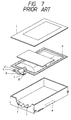
- To facilitate understanding of the present invention, a conventional ink cartridge having a flexible ink bag received therein and a mechanism for installing the ink cartridge will briefly be described below with reference to Fig. 7 and Fig. 8.
- The ink cartridge includes an ink bag a, and a tubular ink outlet piece b is integrated with the ink bag a by applying thermal fusion on one of the thermally fused sides (represented by hatched lines), thereby to allow ink in the ink bag a to be conducted to the outside through the ink outlet piece b. To fixedly hold the ink bag a at a predetermined position in a case e, the ink outlet piece b is provided with a pair of flanges c through which holes d are formed. Thus, the ink bag a can be positioned and fixedly received in the case e by fitting a pair of projections f on the front end part of the case e into the holes d. In addition, the ink cartridge includes a cover j which is placed on the opening of the case e. The cover j is integrated with the case e by thermally sealing the peripheral edge of the case e using an ultrasonic welding process.
- A holder m having the case e received therein is fixedly mounted on an ink jet recording apparatus (not shown). The holder m includes a pair of frames n on the opposite sides thereof so as to guide slidable insertion of the ink cartridge h composed of the ink bag a and the case e. In addition, the holder m includes a pair of leaf springs p at the innermost end of the frame n. When ribs i on the opposite side walls of the ink cartridge h are engaged with the leaf springs p, the ribs i are fixedly retained by the leaf springs p. At this time, an ink feeding needle g projecting from the ink jet recording apparatus is ready to pierce the central part of the ink outlet piece b.
- With such construction, the positional relationship between the ink feeding needle g and the opposing pair of frames n, the positional relationship between the leaf springs p and the ribs i and the positional relationship between the case e and the ink outlet piece b are liable to be undesirably disturbed during steps of fitting and assembling. Thus, there is left unsolved a problem that the ink feeding needle g sometimes cannot be correctly located in alignment with the ink outlet piece b.
- In addition, if the cover j is removed from the case e, it is difficult as a practical matter to reunite the former with the latter again such as by employing a thermal fusion process. For this reason, the ink cartridge h cannot repeatedly be used. Further, since the ink outlet piece b is secured to the thermally fused surfaces of the ink bag a, there is left unsolved another problem that a certain gap appears between the ink outlet piece b and the thermally fused surfaces.
- Accordingly, an object of the present invention is to provide an ink cartridge for an ink jet recording apparatus wherein an ink outlet piece can be correctly aligned with an ink feeding needle regardless of a slight positional deviation from their preferred positions: This object is solved by the ink cartridge according to
independent claim 1. Further advantageous features, aspects and details of the invention are evident from the dependent claims, the description and the drawings. The claims are intended to be understood as a first non-limiting approach of defining the invention in general terms. - The ink cartridge of the invention is preferably for use with an ink jet recording apparatus that performs a recording operation by jetting a series of ink droplets onto a recording paper through a nozzle.
- The present invention provides an ink cartridge for an ink jet recording apparatus wherein a case and a cover placed on the opening of the case can repeatedly be used.
- According to a preferred aspect of the present invention, there is provided an ink cartridge for an ink jet recording apparatus wherein the ink cartridge includes a fitting portion formed on a front plate of a case constituting the ink cartridge, the fitting portion serving to hold and locate an ink outlet piece in an engaged state by engaging the fitting portion with an engaging portion on the ink outlet piece so that an ink feeding needle disposed at an innermost end of the cartridge holder is capable of piercing through the ink outlet piece to reach the interior of the ink bag and at least one position determining hole formed on the front plate of the case, the position determining hole serving to properly locate the ink cartridge relative to a cartridge holder by allowing the insertion of a position determining shaft projecting from the innermost end of the cartridge holder through the position determining hole. With such construction, the ink feeding needle can be correctly located in alignment with the ink outlet piece with the front plate of the case serving as a reference.
- To assure that the case and the cover can repeatedly be used, engagement holes are formed on the front plate of the case positioned so as to engage with the corresponding corner portions disposed on the front edge of a cover, and engagement portions are formed on the opposite side plates of the case at the rear end of the same positioned so as to engage with the corresponding pawls disposed on the opposite sides of the cover at the rear end of the same, whereby the cover can be repeatedly fitted to the case in a snap fit fashion.
- Other objects, features and advantages of the present invention will become apparent from reading of the following description which has been made in conjunction with the accompanying drawings.
- Fig. 1 is a perspective view of a preferred embodiment of an ink cartridge for an ink jet type recording apparatus constructed in accordance with the present invention, particularly illustrating the structure of the ink cartridge in a disassembled state;
- Fig. 2 is a cross-sectional view of an ink outlet piece to be secured to an ink bag;
- Fig. 3 is a sectional view of a position determining/engaging mechanism for the ink outlet piece;
- Fig. 4 is a perspective view of the ink cartridge and a holder, particularly illustrating the structure of the holder in a disassembled state;
- Fig. 5 is a diagrammatic view schematically illustrating an ink flow passage system for the ink jet recording apparatus;
- Fig. 6. is a sectional view of the ink cartridge, particularly illustrating displacement of a detection plate in the ink cartridge;
- Fig. 7 is a perspective view of a conventional ink cartridge, particularly illustrating the structure of the ink cartridge in a disassembled state; and
- Fig. 8 is a perspective view of the ink cartridge and a holder, particularly illustrating the structure of the holder.
- The present invention will hereinafter be described in detail with reference to the accompanying drawings, which illustrate preferred embodiments of the present invention.
- Fig. 1 is a perspective view which illustrates an ink cartridge for an ink jet recording apparatus and which is constructed in accordance with a preferred embodiment of the present invention, Fig. 2 is a cross-sectional view of an ink outlet piece to be fitted to an ink bag, and Fig. 3 is a partially sectioned view of a position determining/engaging mechanism for the ink outlet piece.
- The ink bag designated by
reference numeral 1 is constructed using a laminated aluminum film which is laminated with two films such that the outside of the ink bag is lined with, e.g., a nylon film, while the inside of the same is lined with, e.g., a polyethylene film in order to improve the gas barrier property of the ink bag. These films are thermally fused together along the outer peripheral edge of theink bag 1. - To conduct ink out of the
ink bag 1 to the outside, anink outlet piece 2 is integrated with theink bag 1 by thermal fusion on the front side, as seen in Fig. 1. Theink outlet piece 2 is molded of a plastic material. As shown in Fig. 2, the rear part of theink outlet piece 2, i.e., the joint location where theink bag 1 is thermally fused with theink outlet piece 2, is constructed in a leaf-shaped configuration such that the central part exhibits an convex arc having a large radius of curvature and the opposite ends exhibit an concave arc having a large radius of curvature. With this construction, a gap between theink bag 1 and theink outlet piece 2 is fully filled with molten material during a thermal fusing operation to provide a reliable seal. - The forward half of the
ink outlet piece 2 has a circular sectional shape, and anannular engagement groove 2a for holding theink bag 1 at a predetermined position on a case 4 (similar to the position determiningannular engagement groove 2 disclosed in commonly assigned Japanese Examined Patent Application Publication (Kokai) No. Hei. 2-192953) is formed around the outer periphery of theink outlet piece 2. Afitting portion 4b of thecase 4 is fitted into theengagement groove 2a (see Fig. 3). In addition, achuck portion 2b is formed around the central part of theink outlet piece 2 so as to facilitate grasping of theink bag 1 during a step of automatically receiving theink bag 1 in thecase 4 on a mass production line. A conduit 2c is formed along the center axis of theink outlet piece 2 so as to conduct ink from theink bag 1 to the outside. A sealingmember 3 molded of an elastic material such rubber or the like is fitted into the forward end part of theink outlet piece 2 so as to reliably maintain airtightness between themember 3 and an ink feeding needle 15 (to be described later). Further, a film portion 2d is interposed between the conduit 2c and the sealingmember 3 in order to prevent incorrect printing from being performed due to undesirable elution or deposition of the rubber caused by direct contact of the ink with the sealingmember 3. - The
case 4 for receiving theink bag 1 is designed in a box-shaped configuration having a small thickness. A fittingportion 4b having a semicircular recess to be engaged with theengagement groove 2a of theink outlet piece 2 is formed on a front plate 4a of thecase 4 in a snap-fit fashion. In addition, an opposing pair ofposition determining holes case 4 with the fitting portion located therebetween. As shown in Fig. 4, thecase 4 is correctly held at a predetermined position as seen not only in the upward/downward direction but also in the leftward/rightward direction by inserting aposition determining shaft 16 and aguide shaft 17 on aholder 9 into theposition determining holes - The
ink bag 1 is firmly held in position in the case with the aid of a pressure-sensitive-adhesive double-sided tape (hereinafter referred to simply as an adhesive tape), and adetection plate 5, of which the forward end is bent at a right angle, is adhesively attached to the upper surface of theink bag 1 with the aid of an adhesive tape. As the quantity of the ink in theink bag 1 decreases, thebent part 5a of thedetection plate 5 is projected outside of a rectangular hole 4i at the lower part of thecase 4, whereby a so-called "near-end" state of the ink can be detected by anink end detector 11, as shown in Fig. 6. - A
cover 6 placed on the opening portion of thecase 4 includes a pair of projectingportions 6a along the front edge thereof, and a pair ofpawls 6b on the opposite sides at the rear end thereof. Thus, thecover 6 can be firmly fitted to thecase 4 in a snap-fit fashion by inserting thecorner portions 6a intoholes 4d on thefront plate 4 of thecase 4 and then fitting thepawls 6b intorecesses 4e on side plates 4c of thecase 4 at the rear part of the same. When thecover 6 is to be removed from thecase 4, it is recommended to insert a jig or other tool into acutout 4f on arear plate 4j of thecase 4 and then pry off thecover 6. - A
label 7 having a caution instruction or the like printed thereon is adhesively arranged on thecover 6 in such a manner as to hide thecutout 4f from the outside. This arrangement prevents not only dislodgment of thecover 6 from thecase 4 due to vibration or careless dropping, but also intentional opening of thecover 6. - According to a modified embodiment of the present invention, an ink cartridge may be constructed such that the projecting
portions 6a and thepawls 6b on thecover 6 are eliminated and thecover 6 is firmly held merely by thelabel 7. In this embodiment, it is necessary that thelabel 7 be adhesively placed on thecase 4 while extending from the front plate 4a to therear plate 4j of thecase 4. With this construction, the ink cartridge can be provided at a more inexpensive cost. - Next, a mechanism for installing an
ink cartridge 8 in an ink jet recording apparatus will be described below with reference to Fig. 4. - A
holder 9 is fixedly mounted on the ink jet recording apparatus I (not shown). To assure that theink cartridge 8 is correctly received in theholder 9 and then firmly held at a predetermined position on theholder 9, an opposing pair offrames 10 are arranged for constructing theholder 9. In addition, ashutter 12 is arranged so as to prevent theink feeding needle 15 projecting into the interior of theholder 9 to touch the user's hand when the ink cartridge is received in theholder 9. Theshutter 12 is turnably supported on theholder 9 to turn about arotational center axis 12a so that it normally assumes the position shown by the action of a shutter spring (not shown). While the shutter is in the position shown, it is engaged with pawls of elastically deformable lockarms 10a disposed along the lower edges of theframes 10. - The forwardmost end of each of the
lock arms 10a normally projects into aguide groove 10b extending along the lower edge of theframe 10. Thus, when theink cartridge 8 is inserted midway between both theframes 10, thelock arms 10a are squeezed byribs 4k on the opposite sides of thecase 4 at the forwardmost end of the same so that they are displaced from the engaged state. - Leaf springs 13 arranged at the innermost ends of the opposing pair of
frames 10 project into the region where theink cartridge 8 is to be received. When theink cartridge 8 is inserted and reaches the innermost end of theholder 9 while being guided by aposition determining shaft 16 and aguide shaft 17, theleaf springs 13 engage with theribs 4k on thecase 4, whereby theink cartridge 8 is firmly held in place. - As is best seen in Fig. 4, the
ink feeding needle 15 disposed at the innermost end of thecartridge 9 projects toward theink cartridge 8 at the position where it is located slightly behind theposition determining shaft 16 and theguide pin 17. Thus, when theink cartridge 8 is firmly retained by theleaf spring 13, theink feeding needle 15 pierces through the sealingmember 3 and theink outlet piece 2 to reach the interior of theink bag 1. - In Fig. 4, reference numeral 4w designates ribs which are formed on the opposite side of the
case 4 at the rearmost end of the same so as to prevent erroneous insertion of theink cartridge 8. If theink cartridge 8 is inserted in the reverse direction by mistake, the ribs 4w collide with erroneousinsertion preventing projections 10c on theframes 10, making it impossible for theink cartridge 8 to be inserted into theholder 8 any further. - Fig. 5 is a diagrammatic view which illustrates an ink flow passage system for the ink jet recording apparatus.
- As shown in the drawing, a
filter 21 is arranged on the left-hand end surface of theholder 9 for preventing dust or other foreign material from entering the ink flow passage system. Theink feeding needle 15 is connected to aprinting head 18 via thefilter 21 and anink feeding tube 19. - In Fig. 5,
reference numeral 24 designates a cap disposed outside of a non-printing region. Thecap 24 communicates with awaste liquid bag 26 via awaste liquid tube 22 and apump 23. When aprinting head 18 returns to a waiting position, thecap 24 comes into contact with the nozzle surface of theprinting head 18 so that ink remaining in theprinting head 18 is recovered in a wasteliquid absorbing material 27 in thewaste liquid bag 26 so as to prevent theprinting head 18 from being clogged with used ink when the ink jet recording apparatus is held in an inoperative state. - Next, the installation of the
ink cartridge 8 constructed in the above-mentioned manner will be described below. - The
ink outlet piece 2, the rear half of which has a leaf-shaped cross-sectional contour, can be secured to the upper and lower films of theink bag 1 by thermal fusion not only without any gap therebetween but also without large warpage thereof. - When the
ink bag 1 is received in thecase 4, the forward half of theink outlet piece 2 projecting outside of theink bag 1 is located in alignment with the front plate 4a of thecase 4 so as to allow theengagement groove 2a of theink outlet piece 2 to be engaged with thefitting portion 4b at the central part of the front plate 4a. Thus, theink bag 1 is located and received at a predetermined position on thecase 4 while the front plate 4a of thecase 4 serves as a reference. - Next, the
detection plate 5 is adhesively placed on the upper surface of theink bag 1 using adhesive tape, and thereafter thecover 6 is placed on thecase 4. At this time, while thecorner portions 6a on the front edge of the plate 4a of thecase 4, the rear end part of thecover 6 is depressed with an user's hand, causing thepawls 6b on the opposite sides of thecase 4 at the rear end of the same to be engaged with therecesses 4e on the side plates 4c of thecase 4. Consequently, thecover 6 is firmly fitted into the opening of thecase 4 in the snap-fit fashion. - When the
ink cartridge 8 assembled in the above-described manner is received in theholder 9, theink cartridge 8 having theink outlet piece 2 located ahead thereof is inserted into theholder 9 by sliding the same along theguide grooves 10b of theframes 10. As theribs 4k are slidably displaced in this manner, first they deflect thelock arms 10a in the outward direction so as to allow theshutter 12 to be released from the engaged state. Then, theink cartridge 8 turns the shutter in the upward direction, whereby it is introduced into theholder 7. - When the
ink cartridge 8 is inserted to a position in the vicinity of the innermost end of theholder 9, theposition determining shaft 16 and theguide shaft 17 horizontally projecting toward the front plate 4a of thecase 4 are inserted through the correspondingholes case 4 so that theink cartridge 8 is correctly received in theholder 9 not only in the upward/downward direction but also in the leftward/rightward direction. - Subsequently, when the
ink cartridge 8 is squeezed further to contact the innermost end of theholder 9 with the aid of theposition determining shaft 16 and theguide shaft 17, theink feeding needle 15 projecting from the innermost end of theholder 9 pierces the sealingmember 3 and the film portion 2d so as to be inserted into theink bag 1. At this point, the ink contained in theink bag 1 is ready for use. - While the present invention has been described above with respect to preferred embodiments, various changes and modifications may be made without departure from the scope of the present invention as defined by the appended claims.
Claims (7)
- An ink cartridge (8) for an ink jet recording apparatus having a cartridge holder (9) in which said ink cartridge (8) is inserted, said ink cartridge (8) comprising:- a case (4) having a front plate (4a) and a fitting portion (4b) formed on said front plate (4a);- an ink bag (1) containing a supply of ink, said ink bag (1) being received in said case (4); and- an ink outlet piece (2) having an ink flow path therein communicating with said ink bag (2), so that an ink feeding needle (15) disposed at an innermost end of the cartridge holder (9) is capable of piercing through the ink outlet piece (2) to reach the interior of the ink bag (1), said ink outlet piece (2) having an engaging portion (2a) engaged with said fitting portion (4b) so as to hold and locate said ink outlet piece (2) at a predetermined position relative to said case (4)characterised in that
the case (4) has at least one position determining hole (4g, 4h) being formed in said front plate (4a), said position determining hole (4g, 4h) allowing the insertion of a position determining shaft (16, 17) projecting from the innermost end of said cartridge holder (9) through said position determining hole (4g, 4h) so as to guide and properly locate said ink cartridge (8) relative to said cartridge holder (9), whereby the ink feeding needle (15) projects toward the ink cartridge (8) at a position where it is located slightly behind the position determining shaft (16, 17). - The ink cartridge according to claim 1, wherein said outlet piece (2) comprises an ink conduit tube (2c) extending along a center axis of said outlet piece (2), said ink conduit being sealed with a thin film (2d), and a sealing member (3) made of an elastic material, said sealing member (3) being located on a front surface side of said thin film (2d) away from an ink feeding needle (15) to assure airtightness relative to said ink feeding needle (15).
- The ink cartridge according to claim 1 or 2, further comprising a cover (6) for said case (4), said cover (6) having a pair of pawls (6b) formed on opposite sides of a rear end portion of said cover (6), and wherein engagement holes (4d) are formed on said front plate (4a) of said case (4) so as to be engaged with corresponding projecting portions (6a) on a front edge of said cover (6), and wherein engagement portions (4e) are formed on opposite side plates (4c) of said case (4) at a rear end of said case (4) so as to be engaged with corresponding ones of said pawls (6b).
- The ink cartridge according to any one of the preceding claims, further comprising a plate-shaped detection plate (5) arranged in said case (4), said detection plate (5) being located in a detecting region extending from an upper surface of said ink bag for detecting and indicating an ink near-end state.
- The ink cartridge according to any one of the preceding claims, wherein said ink bag (1) comprises a laminated aluminum film comprising an outer nylon film and an inner polyethylene film.
- The ink cartridge according to any one of the preceding claims, wherein a rear end portion of said ink outlet piece (2) is thermally fused to said ink bag (1), said rear end portion of said ink outlet piece having a leaf-like shape in cross section.
- The ink cartridge according to any one of the preceding claims, wherein a forward end portion of said ink outlet piece (2) is circular in cross section, said engagement portion being defined by an annular groove (2a) formed in said forward end portion.
Applications Claiming Priority (9)
| Application Number | Priority Date | Filing Date | Title |
|---|---|---|---|
| JP121136/91 | 1991-05-27 | ||
| JP12113691A JP3024260B2 (en) | 1991-05-27 | 1991-05-27 | ink cartridge |
| JP166854/91 | 1991-07-08 | ||
| JP166856/91 | 1991-07-08 | ||
| JP166855/91 | 1991-07-08 | ||
| JP16685591A JP3141894B2 (en) | 1991-07-08 | 1991-07-08 | ink cartridge |
| JP16685691A JP3352706B2 (en) | 1991-07-08 | 1991-07-08 | Ink cartridge for inkjet recording device |
| JP16685491A JPH0516377A (en) | 1991-07-08 | 1991-07-08 | Ink cartridge |
| EP92108959A EP0516088B1 (en) | 1991-05-27 | 1992-05-27 | Ink cartridge for ink jet recording apparatus |
Related Parent Applications (2)
| Application Number | Title | Priority Date | Filing Date |
|---|---|---|---|
| EP92108959.5 Division | 1992-05-27 | ||
| EP92108959A Division EP0516088B1 (en) | 1991-05-27 | 1992-05-27 | Ink cartridge for ink jet recording apparatus |
Publications (3)
| Publication Number | Publication Date |
|---|---|
| EP0715958A2 true EP0715958A2 (en) | 1996-06-12 |
| EP0715958A3 EP0715958A3 (en) | 1996-07-17 |
| EP0715958B1 EP0715958B1 (en) | 1998-08-12 |
Family
ID=27470753
Family Applications (2)
| Application Number | Title | Priority Date | Filing Date |
|---|---|---|---|
| EP92108959A Expired - Lifetime EP0516088B1 (en) | 1991-05-27 | 1992-05-27 | Ink cartridge for ink jet recording apparatus |
| EP96103079A Expired - Lifetime EP0715958B1 (en) | 1991-05-27 | 1992-05-27 | Ink cartridge for ink jet recording apparatus |
Family Applications Before (1)
| Application Number | Title | Priority Date | Filing Date |
|---|---|---|---|
| EP92108959A Expired - Lifetime EP0516088B1 (en) | 1991-05-27 | 1992-05-27 | Ink cartridge for ink jet recording apparatus |
Country Status (5)
| Country | Link |
|---|---|
| US (1) | US5666146A (en) |
| EP (2) | EP0516088B1 (en) |
| DE (3) | DE9218185U1 (en) |
| HK (2) | HK1000417A1 (en) |
| SG (1) | SG47827A1 (en) |
Cited By (11)
| Publication number | Priority date | Publication date | Assignee | Title |
|---|---|---|---|---|
| EP0834403A2 (en) * | 1996-10-07 | 1998-04-08 | Seiko Epson Corporation | An ink cartridge |
| EP0857575A2 (en) * | 1997-02-10 | 1998-08-12 | Seiko Epson Corporation | Ink feed container |
| EP0865925A1 (en) * | 1997-03-17 | 1998-09-23 | Pelikan Produktions Ag | Ink cartridge for an ink jet printer or plotter |
| WO1998055323A1 (en) * | 1997-06-04 | 1998-12-10 | Hewlett-Packard Company | An ink container having a multiple function chassis |
| EP0891867A2 (en) * | 1997-07-14 | 1999-01-20 | Owens-Illinois Closure Inc. | Liquid containment and dispensing device with improved resistance to shock loads |
| EP0904940A2 (en) * | 1997-09-26 | 1999-03-31 | Brother Kogyo Kabushiki Kaisha | Ink supplying device |
| EP0890441A3 (en) * | 1997-06-05 | 1999-08-25 | Hewlett-Packard Company | Ink containment system for an ink-jet printer. |
| EP1013449A3 (en) * | 1998-12-24 | 2000-12-06 | Seiko Epson Corporation | Ink bag for ink jet type recording apparatus and package suitable for packing such ink bag |
| US6834945B2 (en) | 2000-01-21 | 2004-12-28 | Seiko Epson Corporation | Ink cartridge for use with recording apparatus and ink jet recording apparatus |
| US7384133B2 (en) | 2003-08-08 | 2008-06-10 | Seiko Epson Corporation | Liquid container capable of maintaining airtightness |
| US8322835B2 (en) | 2007-02-19 | 2012-12-04 | Seiko Epson Corporation | Sealing structure of fluid container, and method of manufacturing and reusing fluid container |
Families Citing this family (77)
| Publication number | Priority date | Publication date | Assignee | Title |
|---|---|---|---|---|
| US6264314B1 (en) * | 1991-05-27 | 2001-07-24 | Seiko Epson Corporation | Ink cartridge for ink jet recording apparatus |
| EP0604127B1 (en) * | 1992-12-22 | 1997-07-02 | Hewlett-Packard Company | Double compartment ink-jet cartridge with optimum snout |
| US5610644A (en) * | 1992-12-22 | 1997-03-11 | Hewlett-Packard Company | Thermal ink-jet pen with a plastic/metal attachment for the cover |
| US6172688B1 (en) * | 1993-08-06 | 2001-01-09 | Canon Aptex Inc. | Printer and printing method |
| JP3158915B2 (en) * | 1994-12-27 | 2001-04-23 | ブラザー工業株式会社 | Mobile ink ejection device |
| JP3417434B2 (en) * | 1995-01-05 | 2003-06-16 | セイコーエプソン株式会社 | Ink cartridge for inkjet printer |
| US5784087A (en) * | 1995-04-27 | 1998-07-21 | Owens-Illinois Closure Inc. | Liquid containment and dispensing device |
| US5751322A (en) * | 1996-02-13 | 1998-05-12 | Hewlett-Packard Company | Limited access needle/septum ink-supply interface mechanism |
| EP0827836B1 (en) * | 1996-02-21 | 2005-05-04 | Seiko Epson Corporation | Ink cartridge |
| IL121640A (en) | 1997-08-27 | 2000-06-01 | Scitex Corp Ltd | Ink cartridge |
| JP3493964B2 (en) | 1997-08-28 | 2004-02-03 | セイコーエプソン株式会社 | Ink cartridge insertion mechanism for inkjet printer |
| US6142622A (en) * | 1997-09-18 | 2000-11-07 | Paxar Corporation | Ink jet printer and method |
| EP1604832A3 (en) | 1998-02-13 | 2006-02-22 | Seiko Epson Corporation | Print head with sub-tank unit connected via a back flow prevention valve |
| US6183072B1 (en) * | 1998-04-29 | 2001-02-06 | Hewlett-Packard Company | Seal using gasket compressed normal to assembly axis of two parts |
| SG95595A1 (en) * | 1998-05-13 | 2003-04-23 | Seiko Epson Corp | Ink cartridge for ink-jet printing apparatus |
| JP3495938B2 (en) * | 1998-10-27 | 2004-02-09 | キヤノン株式会社 | INK JET RECORDING CARTRIDGE, INK JET RECORDING CARTRIDGE MANUFACTURING METHOD, INK JET RECORDING CARTRIDGE MANUFACTURING APPARATUS AND RECORDING APPARATUS |
| DE19915925B4 (en) * | 1999-04-09 | 2007-08-02 | Tally Computerdrucker Gmbh | Ink cartridge or ink bag for ink printers |
| US6280025B1 (en) * | 1999-06-08 | 2001-08-28 | Pitney Bowes Inc. | Ink cartridge receiving pocket assembly |
| DE60141929D1 (en) | 2000-01-21 | 2010-06-02 | Seiko Epson Corp | Ink cartridge and ink jet printing apparatus having such an ink cartridge |
| CN1799846B (en) * | 2000-01-21 | 2010-06-09 | 精工爱普生株式会社 | Ink cartridge for use with recording apparatus and ink jet recording apparatus |
| US6908182B2 (en) | 2000-01-31 | 2005-06-21 | Seiko Epson Corporation | Ink cartridge and ink jet printer |
| KR100389444B1 (en) * | 2000-04-11 | 2003-06-27 | 세이코 엡슨 가부시키가이샤 | Ink cartridge for recording apparatus |
| US6595711B2 (en) * | 2000-05-26 | 2003-07-22 | Legacy Manufacturing, Llc | Printer cartridge having a foam retention clip |
| CA2379725C (en) * | 2001-04-03 | 2007-06-12 | Seiko Epson Corporation | Ink cartridge |
| US6536888B2 (en) | 2001-08-16 | 2003-03-25 | Eastman Kodak Company | Ink cartridge with internal ink bag and method of filling |
| US6554402B2 (en) | 2001-08-16 | 2003-04-29 | Eastman Kodak Company | Ink cartridge with color discrimination structure |
| US6505926B1 (en) | 2001-08-16 | 2003-01-14 | Eastman Kodak Company | Ink cartridge with memory chip and method of assembling |
| JP2003246076A (en) * | 2002-02-22 | 2003-09-02 | Canon Inc | Liquid storage vessel and method of manufacturing the same |
| US6609789B1 (en) | 2002-03-11 | 2003-08-26 | Banctec, Inc. | Ink cartridge |
| MXPA03002490A (en) * | 2002-03-20 | 2004-10-15 | Seiko Epson Corp | Ink cartridge and ink cartridge holder. |
| TWI282310B (en) | 2002-06-28 | 2007-06-11 | Oce Tech Bv | Ink tank |
| US20040012660A1 (en) * | 2002-07-18 | 2004-01-22 | Eastman Kodak Company | Ink cartridge having connectable-disconnectable housing and ink supply bag |
| US6705713B2 (en) | 2002-07-18 | 2004-03-16 | Eastman Kodak Company | Disposable ink assemblage |
| US6702435B2 (en) | 2002-07-18 | 2004-03-09 | Eastman Kodak Company | Ink cartridge having ink identifier oriented to provide ink identification |
| US6715864B2 (en) | 2002-07-18 | 2004-04-06 | Eastman Kodak Company | Disposable ink supply bag having connector-fitting |
| US6712459B2 (en) | 2002-07-18 | 2004-03-30 | Eastman Kodak Company | Ink cartridge having shielded pocket for memory chip |
| US6709093B2 (en) | 2002-08-08 | 2004-03-23 | Eastman Kodak Company | Ink cartridge in which ink supply bag held fast to housing |
| US6755501B2 (en) | 2002-08-08 | 2004-06-29 | Eastman Kodak Company | Alternative ink/cleaner cartridge |
| US6830323B2 (en) | 2002-08-13 | 2004-12-14 | Eastman Kodak Company | Restricting flash spread when welding housing halves of cartridge together |
| US6837576B2 (en) | 2002-08-21 | 2005-01-04 | Eastman Kodak Company | Method of filling ink supply bag for ink cartridge |
| US6705714B1 (en) | 2002-08-21 | 2004-03-16 | Eastman Kodak Company | Ink cartridge having ink supply bag filled to less than capacity and folded in cartridge housing |
| EP1586452B1 (en) * | 2002-11-26 | 2007-07-04 | Seiko Epson Corporation | Ink cartridge and identification block |
| JP3624950B2 (en) * | 2002-11-26 | 2005-03-02 | セイコーエプソン株式会社 | ink cartridge |
| JP3919734B2 (en) * | 2002-12-06 | 2007-05-30 | 株式会社リコー | Ink cartridge, casing thereof, and image forming apparatus |
| US7758172B2 (en) | 2003-07-18 | 2010-07-20 | Seiko Epson Corporation | Injection apparatus and a valve device provided in a passage |
| JP2005053212A (en) * | 2003-07-18 | 2005-03-03 | Seiko Epson Corp | Liquid container |
| EP1498272A1 (en) | 2003-07-18 | 2005-01-19 | Seiko Epson Corporation | Liquid container |
| DE602004022075D1 (en) * | 2003-10-21 | 2009-08-27 | Novo Nordisk As | RESERVOIR DEVICE WITH INTEGRATED FASTENER |
| CN100586414C (en) * | 2003-10-21 | 2010-02-03 | 诺沃挪第克公司 | Reservoir device with inclined needle |
| WO2005120433A1 (en) * | 2004-06-07 | 2005-12-22 | Novo Nordisk A/S | Reservoir with liquidly applied seal |
| JP2006035484A (en) * | 2004-07-23 | 2006-02-09 | Seiko Epson Corp | Liquid container and method for detecting remaining quantity of liquid |
| US20060038863A1 (en) * | 2004-08-18 | 2006-02-23 | Eastman Kodak Company | Refillable chemical cartridge for photoprocessing equipment |
| JP4677788B2 (en) * | 2005-01-14 | 2011-04-27 | セイコーエプソン株式会社 | Ink jet recording apparatus and ink waste liquid management method thereof |
| JP2007038591A (en) * | 2005-08-04 | 2007-02-15 | Seiko Epson Corp | Liquid container, ink cartridge equipped therewith, and inkjet printer |
| CN200960761Y (en) * | 2005-09-04 | 2007-10-17 | 珠海纳思达电子科技有限公司 | Splitting ink box |
| ES2364291T3 (en) * | 2006-11-06 | 2011-08-30 | Seiko Epson Corporation | LIQUID DEPOSIT, DEPOSIT SUPPORT AND LIQUID CONSUMPTION DEVICE. |
| JP4078387B1 (en) * | 2007-06-29 | 2008-04-23 | ワールドネットワーク株式会社 | Ink tank and ink cartridge |
| US20090027462A1 (en) * | 2007-07-24 | 2009-01-29 | Berg Richard H | Wide format ink cartridge |
| JP5141348B2 (en) * | 2008-04-14 | 2013-02-13 | 株式会社リコー | Recording liquid storage container and image forming apparatus |
| JP5032392B2 (en) * | 2008-05-15 | 2012-09-26 | 株式会社セイコーアイ・インフォテック | ink cartridge |
| JP5341697B2 (en) * | 2008-11-26 | 2013-11-13 | 株式会社セイコーアイ・インフォテック | Ink cartridge and remaining amount display method |
| DE202010013614U1 (en) * | 2010-09-20 | 2010-11-25 | Lincoln Gmbh | Lubricant collecting container |
| DE102010055783B3 (en) | 2010-12-23 | 2012-06-14 | Marabu Gmbh & Co. Kg | Ink cartridge for inkjet printers |
| WO2012153287A2 (en) * | 2011-05-11 | 2012-11-15 | Nutec Digital Ink (Pty) Ltd | Ink cartridge |
| US9624978B2 (en) * | 2011-09-13 | 2017-04-18 | Ntn Corporation | Bearing device |
| JP5842616B2 (en) | 2012-01-05 | 2016-01-13 | 株式会社リコー | Liquid cartridge, image forming apparatus |
| FR3002121B1 (en) * | 2013-02-20 | 2015-04-03 | Rexam Dispensing Smt | PRODUCT DISPENSING ASSEMBLY COMPRISING A CASE AND A CASSETTE |
| US9132648B2 (en) | 2014-02-19 | 2015-09-15 | Ricoh Company, Ltd. | Fluid cartridge label stiffener |
| JP6632221B2 (en) * | 2015-05-22 | 2020-01-22 | キヤノン株式会社 | Liquid ejection head |
| WO2020013839A1 (en) | 2018-07-13 | 2020-01-16 | Hewlett-Packard Development Company, L.P. | Coupling systems |
| US11198299B2 (en) | 2018-07-13 | 2021-12-14 | Hewlett-Packard Development Company, L.P. | Collar for fluid barrier |
| EP3687810B1 (en) | 2018-07-13 | 2023-04-12 | Hewlett-Packard Development Company, L.P. | Pliable print liquid supply reservoirs with offset spout |
| CN112055658B (en) * | 2018-07-13 | 2022-06-21 | 惠普发展公司,有限责任合伙企业 | Clamping plate with wedge-shaped fork end for printing liquid supply source |
| EP4129699A1 (en) | 2018-07-13 | 2023-02-08 | Hewlett-Packard Development Company L.P. | Spouts with angled clamp flanges for a print liquid supply |
| JP7447508B2 (en) | 2020-01-28 | 2024-03-12 | セイコーエプソン株式会社 | liquid storage container |
| JP2021160321A (en) | 2020-04-03 | 2021-10-11 | セイコーエプソン株式会社 | Liquid storage container |
| TWI753590B (en) * | 2020-09-29 | 2022-01-21 | 臺灣納米科技股份有限公司 | Ink cartridge with replaceable ink bag |
Citations (10)
| Publication number | Priority date | Publication date | Assignee | Title |
|---|---|---|---|---|
| FR2485991A1 (en) * | 1980-07-04 | 1982-01-08 | Canon Kk | Ink supply system for ink jet printer - has flexible main reservoir accommodating pressure variations in secondary reservoir supplying ink jet |
| JPS58211482A (en) * | 1982-06-01 | 1983-12-08 | Canon Inc | Ink container |
| JPS59192574A (en) * | 1983-04-18 | 1984-10-31 | Ricoh Co Ltd | Ink cartridge for on-demand type ink jet printer |
| JPS60125671A (en) * | 1983-12-12 | 1985-07-04 | Ricoh Co Ltd | Ink bag of ink cartridge in on-demand type ink jet printer |
| JPH01180351A (en) * | 1988-01-12 | 1989-07-18 | Seiko Epson Corp | Ink reservoir |
| EP0364284A2 (en) * | 1988-10-14 | 1990-04-18 | Seiko Epson Corporation | Ink cartridge for an ink jet printer |
| JPH02187349A (en) * | 1989-01-13 | 1990-07-23 | Canon Inc | Liquid jet recording head |
| EP0380199A2 (en) * | 1989-01-27 | 1990-08-01 | Shimadzu Corporation | Printer with interchangeable print heads |
| US4974977A (en) * | 1989-01-19 | 1990-12-04 | Banctec, Inc. | Print ribbon cartridge with vacuum buffer chambers |
| EP0440261A2 (en) * | 1990-02-02 | 1991-08-07 | Canon Kabushiki Kaisha | Ink jet apparatus and ink jet cartridge therefor |
Family Cites Families (16)
| Publication number | Priority date | Publication date | Assignee | Title |
|---|---|---|---|---|
| US3913774A (en) * | 1973-03-12 | 1975-10-21 | Leslie Vajtay | End caps for containers |
| US4303929A (en) * | 1980-06-04 | 1981-12-01 | International Business Machines Corporation | Air purging pump for ink jet printers |
| US4335950A (en) * | 1980-12-24 | 1982-06-22 | Xerox Corporation | Frame assembly with upper and lower frame members for automatic reproducing apparatus |
| GB2112715B (en) * | 1981-09-30 | 1985-07-31 | Shinshu Seiki Kk | Ink jet recording apparatus |
| JPS59212272A (en) * | 1983-05-17 | 1984-12-01 | Canon Inc | Ink jet recorder |
| JPS59227458A (en) * | 1983-06-08 | 1984-12-20 | Ricoh Co Ltd | Ink cassette in ink jet recording apparatus |
| JPH0698774B2 (en) * | 1984-02-09 | 1994-12-07 | キヤノン株式会社 | Ink container |
| US4551734A (en) * | 1984-12-06 | 1985-11-05 | Tektronix, Inc. | Ink cartridge with ink level sensor |
| JPS6260335A (en) * | 1985-09-11 | 1987-03-17 | Hitachi Ltd | Decentralized terminal equipment processing system |
| JPS6260334A (en) * | 1985-09-11 | 1987-03-17 | Hitachi Ltd | Method and equipment for switching multiplex transmission line |
| JPH0825279B2 (en) * | 1986-06-25 | 1996-03-13 | キヤノン株式会社 | Ink supply device |
| US4776714A (en) * | 1986-07-15 | 1988-10-11 | Monarch Marking Systems, Inc. | Ink ribbon cassette with movable guide rolls |
| JP2545230B2 (en) * | 1987-05-28 | 1996-10-16 | セイコーエプソン株式会社 | Ink supply container |
| JP2691716B2 (en) * | 1987-11-30 | 1997-12-17 | キヤノン株式会社 | Ink cartridge holding device |
| JP2932513B2 (en) * | 1988-10-14 | 1999-08-09 | セイコーエプソン株式会社 | ink cartridge |
| US5307091A (en) * | 1992-03-16 | 1994-04-26 | Lexmark International, Inc. | Jet ink refill supply |
-
1992
- 1992-05-27 DE DE9218185U patent/DE9218185U1/en not_active Expired - Lifetime
- 1992-05-27 SG SG1996004592A patent/SG47827A1/en unknown
- 1992-05-27 DE DE69226662T patent/DE69226662T2/en not_active Expired - Lifetime
- 1992-05-27 DE DE69214512T patent/DE69214512T2/en not_active Expired - Lifetime
- 1992-05-27 EP EP92108959A patent/EP0516088B1/en not_active Expired - Lifetime
- 1992-05-27 EP EP96103079A patent/EP0715958B1/en not_active Expired - Lifetime
-
1994
- 1994-08-25 US US08/295,040 patent/US5666146A/en not_active Expired - Lifetime
-
1997
- 1997-10-24 HK HK97102028A patent/HK1000417A1/en not_active IP Right Cessation
-
1998
- 1998-06-16 HK HK98105407A patent/HK1006366A1/en not_active IP Right Cessation
Patent Citations (10)
| Publication number | Priority date | Publication date | Assignee | Title |
|---|---|---|---|---|
| FR2485991A1 (en) * | 1980-07-04 | 1982-01-08 | Canon Kk | Ink supply system for ink jet printer - has flexible main reservoir accommodating pressure variations in secondary reservoir supplying ink jet |
| JPS58211482A (en) * | 1982-06-01 | 1983-12-08 | Canon Inc | Ink container |
| JPS59192574A (en) * | 1983-04-18 | 1984-10-31 | Ricoh Co Ltd | Ink cartridge for on-demand type ink jet printer |
| JPS60125671A (en) * | 1983-12-12 | 1985-07-04 | Ricoh Co Ltd | Ink bag of ink cartridge in on-demand type ink jet printer |
| JPH01180351A (en) * | 1988-01-12 | 1989-07-18 | Seiko Epson Corp | Ink reservoir |
| EP0364284A2 (en) * | 1988-10-14 | 1990-04-18 | Seiko Epson Corporation | Ink cartridge for an ink jet printer |
| JPH02187349A (en) * | 1989-01-13 | 1990-07-23 | Canon Inc | Liquid jet recording head |
| US4974977A (en) * | 1989-01-19 | 1990-12-04 | Banctec, Inc. | Print ribbon cartridge with vacuum buffer chambers |
| EP0380199A2 (en) * | 1989-01-27 | 1990-08-01 | Shimadzu Corporation | Printer with interchangeable print heads |
| EP0440261A2 (en) * | 1990-02-02 | 1991-08-07 | Canon Kabushiki Kaisha | Ink jet apparatus and ink jet cartridge therefor |
Non-Patent Citations (5)
| Title |
|---|
| PATENT ABSTRACTS OF JAPAN vol. 13, no. 462 (M-881) [3810] , 19 October 1989 & JP-A-01 180351 (S. KASAI), 18 July 1989, * |
| PATENT ABSTRACTS OF JAPAN vol. 14, no. 469 (M-1034), 12 October 1990 & JP-A-02 187349 (K. MAKOTO), 23 July 1990, * |
| PATENT ABSTRACTS OF JAPAN vol. 8, no. 61 (M-284) [1498] , 23 March 1984 & JP-A-58 211482 (H. KIYOUGOKU), 8 December 1983, * |
| PATENT ABSTRACTS OF JAPAN vol. 9, no. 282 (M-428) [2005] , 9 November 1985 & JP-A-60 125671 (H. YAMAZAKI), 4 July 1985, * |
| PATENT ABSTRACTS OF JAPAN vol. 9, no. 57 (M-363) [1780] , 13 March 1985 & JP-A-59 192574 (H. YAMAZAKI), 31 October 1984, * |
Cited By (30)
| Publication number | Priority date | Publication date | Assignee | Title |
|---|---|---|---|---|
| US6053606A (en) * | 1996-10-07 | 2000-04-25 | Seiko Epson Corporation | Ink cartridge |
| EP0834403A3 (en) * | 1996-10-07 | 1998-08-12 | Seiko Epson Corporation | An ink cartridge |
| CN1081550C (en) * | 1996-10-07 | 2002-03-27 | 精工爱普生株式会社 | Ink cartridge |
| EP0834403A2 (en) * | 1996-10-07 | 1998-04-08 | Seiko Epson Corporation | An ink cartridge |
| EP0857575A2 (en) * | 1997-02-10 | 1998-08-12 | Seiko Epson Corporation | Ink feed container |
| US6375316B1 (en) | 1997-02-10 | 2002-04-23 | Seiko Epson Corporation | Ink feed container for accommodating a plurality of ink storage bags in a case main body with partitioning members |
| EP0857575A3 (en) * | 1997-02-10 | 1999-04-14 | Seiko Epson Corporation | Ink feed container |
| US6106112A (en) * | 1997-02-10 | 2000-08-22 | Seiko Epson Corporation | Ink feed container |
| EP0865925A1 (en) * | 1997-03-17 | 1998-09-23 | Pelikan Produktions Ag | Ink cartridge for an ink jet printer or plotter |
| WO1998055323A1 (en) * | 1997-06-04 | 1998-12-10 | Hewlett-Packard Company | An ink container having a multiple function chassis |
| US6010210A (en) * | 1997-06-04 | 2000-01-04 | Hewlett-Packard Company | Ink container having a multiple function chassis |
| US6386675B2 (en) | 1997-06-04 | 2002-05-14 | Hewlett-Packard Company | Ink container having a multiple function chassis |
| EP0890441A3 (en) * | 1997-06-05 | 1999-08-25 | Hewlett-Packard Company | Ink containment system for an ink-jet printer. |
| US6158853A (en) * | 1997-06-05 | 2000-12-12 | Hewlett-Packard Company | Ink containment system including a plural-walled bag formed of inner and outer film layers |
| EP0891867A3 (en) * | 1997-07-14 | 1999-05-12 | Owens-Illinois Closure Inc. | Liquid containment and dispensing device with improved resistance to shock loads |
| EP0891867A2 (en) * | 1997-07-14 | 1999-01-20 | Owens-Illinois Closure Inc. | Liquid containment and dispensing device with improved resistance to shock loads |
| EP0904940A3 (en) * | 1997-09-26 | 2000-11-02 | Brother Kogyo Kabushiki Kaisha | Ink supplying device |
| EP0904940A2 (en) * | 1997-09-26 | 1999-03-31 | Brother Kogyo Kabushiki Kaisha | Ink supplying device |
| US6276787B1 (en) | 1997-09-26 | 2001-08-21 | Brother Kogyo Kabushiki Kaisha | Ink supplying device |
| EP1013449A3 (en) * | 1998-12-24 | 2000-12-06 | Seiko Epson Corporation | Ink bag for ink jet type recording apparatus and package suitable for packing such ink bag |
| US6220702B1 (en) | 1998-12-24 | 2001-04-24 | Seiko Epson Corporation | Ink bag for ink jet type recording apparatus and package suitable for packing such ink bag |
| US6834945B2 (en) | 2000-01-21 | 2004-12-28 | Seiko Epson Corporation | Ink cartridge for use with recording apparatus and ink jet recording apparatus |
| US6874876B2 (en) | 2000-01-21 | 2005-04-05 | Seiko Epson Corporation | Ink cartridge for use with recording apparatus and ink jet recording apparatus |
| US7380909B2 (en) | 2000-01-21 | 2008-06-03 | Seiko Epson Corporation | Ink cartridge for use with recording apparatus and ink jet recording apparatus |
| US7566120B2 (en) | 2000-01-21 | 2009-07-28 | Seiko Epson Corporation | Ink cartridge for use with recording apparatus and ink jet recording apparatus |
| US7384133B2 (en) | 2003-08-08 | 2008-06-10 | Seiko Epson Corporation | Liquid container capable of maintaining airtightness |
| US8083335B2 (en) | 2003-08-08 | 2011-12-27 | Seiko Epson Corporation | Liquid container |
| US8210670B2 (en) | 2003-08-08 | 2012-07-03 | Seiko Epson Corporation | Liquid container |
| US8668317B2 (en) | 2003-08-08 | 2014-03-11 | Seiko Epson Corporation | Liquid container |
| US8322835B2 (en) | 2007-02-19 | 2012-12-04 | Seiko Epson Corporation | Sealing structure of fluid container, and method of manufacturing and reusing fluid container |
Also Published As
| Publication number | Publication date |
|---|---|
| DE69214512T2 (en) | 1997-03-20 |
| DE69214512D1 (en) | 1996-11-21 |
| SG47827A1 (en) | 1998-04-17 |
| EP0516088A2 (en) | 1992-12-02 |
| EP0715958B1 (en) | 1998-08-12 |
| EP0516088A3 (en) | 1992-12-23 |
| EP0516088B1 (en) | 1996-10-16 |
| DE9218185U1 (en) | 1993-09-02 |
| HK1006366A1 (en) | 1999-02-26 |
| DE69226662D1 (en) | 1998-09-17 |
| DE69226662T2 (en) | 1998-12-24 |
| HK1000417A1 (en) | 1998-03-20 |
| EP0715958A3 (en) | 1996-07-17 |
| US5666146A (en) | 1997-09-09 |
Similar Documents
| Publication | Publication Date | Title |
|---|---|---|
| EP0715958B1 (en) | Ink cartridge for ink jet recording apparatus | |
| US6264314B1 (en) | Ink cartridge for ink jet recording apparatus | |
| US6102533A (en) | Ink container, ink container holder for removably holding ink container, and ink container cap | |
| CN114834159B (en) | Ink replenishing container, ink replenishing system, and adapter for ink replenishment | |
| JPH0516377A (en) | Ink cartridge | |
| EP1264696B1 (en) | Ink jet cartridge with discriminating features | |
| US6511167B1 (en) | Ink container, holder for ink container, ink jet recording apparatus having holder and mounting method for mounting ink container to holder | |
| US6443567B1 (en) | Liquid ejecting cartridge and recording device using same | |
| KR100416332B1 (en) | Ink cartridge and its construction method | |
| US6530654B2 (en) | Ink container, valve unit for ink container, ink jet head cartridge having ink container and ink jet recording apparatus | |
| US6041805A (en) | Valve assembly for a removable ink cartridge | |
| US5992975A (en) | Electrical interconnect for an ink container | |
| EP0604118B1 (en) | Ink cartridge with ink level indicator | |
| JP3024260B2 (en) | ink cartridge | |
| JP3428038B2 (en) | Ink jet recording device | |
| US6786584B2 (en) | Ink housing device reliably preventing ink leakage | |
| US5793387A (en) | Method and apparatus for ink-jet ink level detection | |
| JPH0516379A (en) | Ink cartridge of ink jet recorder | |
| JPH0516378A (en) | Ink cartridge | |
| US20040027431A1 (en) | Ink cartridge in which ink supply bag held fast to housing | |
| JP2001260390A (en) | Ink cartridge | |
| EP2567820B1 (en) | Ink cartridge and inkjet printer | |
| JP3133929B2 (en) | Ink tank and inkjet recording device | |
| JP2000313120A (en) | Ink jet recording apparatus and ink bag attaching method in ink tank | |
| JPH0344531Y2 (en) |
Legal Events
| Date | Code | Title | Description |
|---|---|---|---|
| PUAI | Public reference made under article 153(3) epc to a published international application that has entered the european phase |
Free format text: ORIGINAL CODE: 0009012 |
|
| PUAL | Search report despatched |
Free format text: ORIGINAL CODE: 0009013 |
|
| 17P | Request for examination filed |
Effective date: 19960229 |
|
| AC | Divisional application: reference to earlier application |
Ref document number: 516088 Country of ref document: EP |
|
| AK | Designated contracting states |
Kind code of ref document: A2 Designated state(s): CH DE FR GB IT LI NL SE |
|
| RIN1 | Information on inventor provided before grant (corrected) |
Inventor name: ISONO, MASAHIRO Inventor name: KAWAKAMI, KAZUHISA Inventor name: MOCHIZUKI, SEIJI |
|
| RTI1 | Title (correction) | ||
| AK | Designated contracting states |
Kind code of ref document: A3 Designated state(s): CH DE FR GB IT LI NL SE |
|
| 17Q | First examination report despatched |
Effective date: 19970217 |
|
| GRAG | Despatch of communication of intention to grant |
Free format text: ORIGINAL CODE: EPIDOS AGRA |
|
| GRAG | Despatch of communication of intention to grant |
Free format text: ORIGINAL CODE: EPIDOS AGRA |
|
| GRAH | Despatch of communication of intention to grant a patent |
Free format text: ORIGINAL CODE: EPIDOS IGRA |
|
| GRAH | Despatch of communication of intention to grant a patent |
Free format text: ORIGINAL CODE: EPIDOS IGRA |
|
| GRAA | (expected) grant |
Free format text: ORIGINAL CODE: 0009210 |
|
| AC | Divisional application: reference to earlier application |
Ref document number: 516088 Country of ref document: EP |
|
| AK | Designated contracting states |
Kind code of ref document: B1 Designated state(s): CH DE FR GB IT LI NL SE |
|
| REG | Reference to a national code |
Ref country code: CH Ref legal event code: NV Representative=s name: BOVARD AG PATENTANWAELTE Ref country code: CH Ref legal event code: EP |
|
| REF | Corresponds to: |
Ref document number: 69226662 Country of ref document: DE Date of ref document: 19980917 |
|
| ET | Fr: translation filed | ||
| PLBE | No opposition filed within time limit |
Free format text: ORIGINAL CODE: 0009261 |
|
| STAA | Information on the status of an ep patent application or granted ep patent |
Free format text: STATUS: NO OPPOSITION FILED WITHIN TIME LIMIT |
|
| 26N | No opposition filed | ||
| REG | Reference to a national code |
Ref country code: GB Ref legal event code: IF02 |
|
| REG | Reference to a national code |
Ref country code: FR Ref legal event code: CL |
|
| REG | Reference to a national code |
Ref country code: CH Ref legal event code: PFA Owner name: SEIKO EPSON CORPORATION Free format text: SEIKO EPSON CORPORATION#4-1, NISHISHINJUKU 2-CHOME#SHINJUKU-KU TOKYO-TO (JP) -TRANSFER TO- SEIKO EPSON CORPORATION#4-1, NISHISHINJUKU 2-CHOME#SHINJUKU-KU TOKYO-TO (JP) |
|
| PGFP | Annual fee paid to national office [announced via postgrant information from national office to epo] |
Ref country code: FR Payment date: 20110523 Year of fee payment: 20 Ref country code: CH Payment date: 20110512 Year of fee payment: 20 Ref country code: SE Payment date: 20110512 Year of fee payment: 20 |
|
| PGFP | Annual fee paid to national office [announced via postgrant information from national office to epo] |
Ref country code: GB Payment date: 20110525 Year of fee payment: 20 Ref country code: NL Payment date: 20110520 Year of fee payment: 20 |
|
| PGFP | Annual fee paid to national office [announced via postgrant information from national office to epo] |
Ref country code: DE Payment date: 20110525 Year of fee payment: 20 Ref country code: IT Payment date: 20110523 Year of fee payment: 20 |
|
| REG | Reference to a national code |
Ref country code: DE Ref legal event code: R071 Ref document number: 69226662 Country of ref document: DE |
|
| REG | Reference to a national code |
Ref country code: NL Ref legal event code: V4 Effective date: 20120527 Ref country code: DE Ref legal event code: R071 Ref document number: 69226662 Country of ref document: DE |
|
| REG | Reference to a national code |
Ref country code: CH Ref legal event code: PL |
|
| REG | Reference to a national code |
Ref country code: GB Ref legal event code: PE20 Expiry date: 20120526 |
|
| REG | Reference to a national code |
Ref country code: SE Ref legal event code: EUG |
|
| PG25 | Lapsed in a contracting state [announced via postgrant information from national office to epo] |
Ref country code: DE Free format text: LAPSE BECAUSE OF EXPIRATION OF PROTECTION Effective date: 20120530 |
|
| PG25 | Lapsed in a contracting state [announced via postgrant information from national office to epo] |
Ref country code: GB Free format text: LAPSE BECAUSE OF EXPIRATION OF PROTECTION Effective date: 20120526 |