EP0717551A2 - Image processing apparatus - Google Patents
Image processing apparatus Download PDFInfo
- Publication number
- EP0717551A2 EP0717551A2 EP96200453A EP96200453A EP0717551A2 EP 0717551 A2 EP0717551 A2 EP 0717551A2 EP 96200453 A EP96200453 A EP 96200453A EP 96200453 A EP96200453 A EP 96200453A EP 0717551 A2 EP0717551 A2 EP 0717551A2
- Authority
- EP
- European Patent Office
- Prior art keywords
- image data
- signal
- data
- level
- bit image
- Prior art date
- Legal status (The legal status is an assumption and is not a legal conclusion. Google has not performed a legal analysis and makes no representation as to the accuracy of the status listed.)
- Granted
Links
Images


Classifications
-
- H—ELECTRICITY
- H04—ELECTRIC COMMUNICATION TECHNIQUE
- H04N—PICTORIAL COMMUNICATION, e.g. TELEVISION
- H04N1/00—Scanning, transmission or reproduction of documents or the like, e.g. facsimile transmission; Details thereof
- H04N1/40—Picture signal circuits
- H04N1/405—Halftoning, i.e. converting the picture signal of a continuous-tone original into a corresponding signal showing only two levels
- H04N1/4055—Halftoning, i.e. converting the picture signal of a continuous-tone original into a corresponding signal showing only two levels producing a clustered dots or a size modulated halftone pattern
- H04N1/4056—Halftoning, i.e. converting the picture signal of a continuous-tone original into a corresponding signal showing only two levels producing a clustered dots or a size modulated halftone pattern the pattern varying in one dimension only, e.g. dash length, pulse width modulation [PWM]
-
- H—ELECTRICITY
- H04—ELECTRIC COMMUNICATION TECHNIQUE
- H04N—PICTORIAL COMMUNICATION, e.g. TELEVISION
- H04N1/00—Scanning, transmission or reproduction of documents or the like, e.g. facsimile transmission; Details thereof
- H04N1/40—Picture signal circuits
- H04N1/40062—Discrimination between different image types, e.g. two-tone, continuous tone
-
- H—ELECTRICITY
- H04—ELECTRIC COMMUNICATION TECHNIQUE
- H04N—PICTORIAL COMMUNICATION, e.g. TELEVISION
- H04N1/00—Scanning, transmission or reproduction of documents or the like, e.g. facsimile transmission; Details thereof
- H04N1/40—Picture signal circuits
- H04N1/40075—Descreening, i.e. converting a halftone signal into a corresponding continuous-tone signal; Rescreening, i.e. combined descreening and halftoning
-
- H—ELECTRICITY
- H04—ELECTRIC COMMUNICATION TECHNIQUE
- H04N—PICTORIAL COMMUNICATION, e.g. TELEVISION
- H04N1/00—Scanning, transmission or reproduction of documents or the like, e.g. facsimile transmission; Details thereof
- H04N1/40—Picture signal circuits
- H04N1/407—Control or modification of tonal gradation or of extreme levels, e.g. background level
-
- F—MECHANICAL ENGINEERING; LIGHTING; HEATING; WEAPONS; BLASTING
- F02—COMBUSTION ENGINES; HOT-GAS OR COMBUSTION-PRODUCT ENGINE PLANTS
- F02B—INTERNAL-COMBUSTION PISTON ENGINES; COMBUSTION ENGINES IN GENERAL
- F02B75/00—Other engines
- F02B75/02—Engines characterised by their cycles, e.g. six-stroke
- F02B2075/022—Engines characterised by their cycles, e.g. six-stroke having less than six strokes per cycle
- F02B2075/027—Engines characterised by their cycles, e.g. six-stroke having less than six strokes per cycle four
Definitions
- the present invention relates to an image processing apparatus for processing an image signal.
- a conventional digital printer since an output is constituted by bi-level data corresponding to on/off of dots, input image data (8 bits) from an input system, e.g., a CCD, is bi-level processed by a dither method, and gradation of an original image is expressed by a matrix consisting of a plurality of pixels.
- a resolution is degraded if gradation is improved. For example, in order to reproduce 17 gray levels including white, a threshold value matrix consisting of 4 x 4 pixels is necessary, and in order to reproduce 65 gray levels, a threshold value matrix consisting of 8 x 8 pixels is necessary.
- a threshold value is periodically repeated in units of threshold value matrices. For example, if a dot image is scanned, a difference between original image data and a threshold value periodically varies, and a low-frequency moiré pattern is formed in an output image resulting in a degraded image quality.
- An averaging error minimization method wherein an error in an output pixel against original image data is compensated for the surrounding pixels so as to satisfactorily reproduce gradation of the original image data, has been proposed. This method is effective for eliminating moiré pattern.
- bi-level image data In the bi-level methods, original image data is compressed at high density in view of data volume. For example, if input image data has 8 bits per pixel, bi-level image data has 1 bit per pixel, resulting in 1/8 compression. Therefore, an image memory, an electronic file system, and the like for accumulating image data need only have a small capacity, and this is advantageous for communication for transferring image data. Thus, the above-mentioned techniques are indispensable for image processing.
- Fig. 7A is for explaining the dither method.
- One input pixel 28 is assigned to one component of the threshold value matrix 25.
- Fig. 7B is for explaining the density pattern method.
- One input pixel 28 is assigned to all the components of the threshold value matrix 25. More specifically, in the density pattern method, one pixel of an input image is displayed by a plurality of cells on the display screen 26.
- the dither method and the density pattern method are not essentially different from each other, except that one input pixel is assigned to one or all the pixels of the threshold value matrix.
- an intermediate method therebetween is present.
- a method in which one input pixel is assigned to a plurality of components (four (2 x 2) components in Fig. 7B) of the threshold value matrix has been proposed. Therefore, no essential difference is present between the above methods, and the dither method, the density pattern method, and an intermediate method will be called a dither method.
- an image output is produced as bi-level data, it is constituted only by white or black, i.e., "0" or "1", and it is impossible to control the density of an image.
- various image output apparatuses e.g., a laser beam printer, an ink-jet printer, a CRT device, and the like, are used. In this case, these output apparatuses respectively have their unique output characteristics, and an output density may often vary using the same bi-level signal.
- a laser beam printer on/off operation of a laser beam onto a photosensitive drum is controlled so as to form an electrostatic latent image, and the latent image is developed, thereby obtaining a visible image.
- the potential of a latent image changes in accordance with an ON time of the laser beam.
- the ON time and the potential have a nonlinear relationship, and the potential and a developing density also have a nonlinear relationship. Since the laser beam printer alone poses such many variation factors, outputs from different output apparatuses vary widely, and an output reproduced image is often considerably different from an expected one using the same bi-level signal.
- EP-A-024902 discloses apparatus and a method for converting one bit image data into a multi-level image data output which may be used in a subsequent printing process (which is not disclosed).
- It comprises parallel area integration and edge extraction filters, and an adder adding the two multi-bit outputs thereof to produce a multi-bit signal, which is then either halftone converted or used directly.
- Various aspects of the present invention are concerned with: providing an improved image processing apparatus; providing an image processing apparatus which can provide a high-quality reproduced image; providing an image processing apparatus which can provide a good reproduced image with a simple arrangement; providing an image processing apparatus which reproduces a high-quality image using compressed pixel data; providing an image processing apparatus which facilitates density control of a reproduced image; providing an image processing apparatus which can accurately reproduce an original image; providing an image output apparatus which can provide a high-quality reproduction output with a small data volume; and providing an improved an image processing apparatus having an image identification function.
- EP-A-0,04,902 discloses one-bit pixel input data being converted into multi-bit per pixel output image data. However this specification is not concerned with matching image data processing to different image forming means.
- apparatus for generating signals as set out in claim 1.
- Fig. 1 is a circuit diagram of an image processing apparatus according to a first embodiment of the present invention.
- a digital data output device 1 A/D converts image data from a CCD sensor or a video camera (neither are shown), and outputs digital data of a predetermined number of bits (in this embodiment, 8 bits).
- a bi-level processor 2 performs halftone processing for 8-bit pixel data output from the output device 1 using the systematic dither method or the average error minimization method, and compressed it to data having 1 bit per pixel.
- a memory 3 comprising a RAM or an electronic file stores a predetermined volume of bi-level data (1-bit data) output from the bi-level processor 2.
- a multi-level processor 4 converts the bi-level data output from the memory 3 into multi-level data having 8 bits per pixel.
- the multi-level data output from the multi-level processor 4 is input to a PWM (pulse width modulation) circuit 5.
- PWM pulse width modulation
- the bi-level data output from the memory 3 is input to the multi-level processor 4, and is converted again to multi-level data consisting of 8 bits per pixel. The converted data is then transferred to the PWM circuit 5.
- the PWM circuit 5 performs pulse width modulation processing for the input 8-bit pixel data, and outputs it to a terminal 39 as a PWM signal. Note that numbers on respective lines in Fig. 1 represent the numbers of bits, and this also applies to Figs. 3, 4, and 6.
- Fig. 3 is a detailed block diagram of the multi-level processor 4.
- bi-level data of "0" (white) or "1" (black), which is output from the memory 3 and is input to a terminal 6, is converted to 8-bit data by an 8-bit converter 7.
- the converted 8-bit data is sequentially stored in a buffer memory 8 consisting of two lines (when one line is used for a write mode, the other one is used for a read mode) or several lines.
- the data stored in the buffer memory 8 is read out and is subjected to spatial filter processing by a smoothing circuit 9.
- a spatial filter a one-dimensional or two-dimensional spatial filter can be used, and a weighted averaging filter, a Gaussian filter, or a composite filter for averaging and edge emphasis is preferable.
- the spatial filter can be selected from a plurality of filters in accordance with image data to be processed. If bi-level data input to the multi-level processor 4 is obtained by various algorithms, one of several spatial filters can be appropriately selected, so that optimal multi-level data can be obtained from any bi-level data.
- Multi-level data output from the smoothing circuit 9 is input to the PWM circuit 5 through a terminal 10.
- Fig. 4 is a detailed block diagram of the PWM circuit 5.
- the multi-level data output from the multi-level processor 4 is converted to an analog signal by a digital-to-analog (D/A) converter 11, and each pixel data is sequentially input to one input terminal of a comparator 12.
- a pattern signal generator 13 produces a triangular wave signal 56 in a given cycle, e.g., for each predetermined number of pixels of the digital data, and inputs it to the other input terminal of the comparator 12.
- Master clocks 52 generated from an oscillator (master clock generator) 15 are counted down to, e.g., a 1/4 cycle by a timing signal generator 14, so as to be converted to pixel clocks 51, in synchronism with an H-SYNC signal 55 which is generated from an H-SYNC signal generator 16 for each line.
- the pixel clocks 51 serve as transfer clocks of pixel data, and as latch timing clocks of the D/A converter 11.
- the image processing apparatus of this embodiment is applied to a laser beam printer. Therefore, the H-SYNC signal 55 corresponds to a known BD (beam detect) signal indicating a scan position of a beam.
- the comparator 12 compares levels of an analog image signal 53 and the triangular wave signal 56, and outputs a PWM signal 39.
- the PWM signal 39 is input to a modulator (e.g., a laser driver 40 shown in Fig. 2).
- a laser beam is turned on or off in accordance with the pulse width, and a halftone image is formed on a recording medium (a photosensitive drum 45 shown in Fig. 2).
- Fig. 5 is a timing chart for explaining signal waveforms in the respective portion of the multi-level processor 5 shown in Fig. 4.
- the master clocks 52 correspond to outputs from the oscillator 15, and the BD signal 55 corresponds to the H-SYNC signal, as described above.
- the pixel clocks 51 are obtained by counting down the master clocks 52 by the timing signal generator 14. More specifically, the pixel clocks 51 are obtained by counting down the master clocks 52 to a 1/4 cycle by the timing signal generator 14 in synchronism with the H-SYNC signal.
- Screen clocks 54 are obtained by counting down the pixel clocks 51 to a 1/3 cycle by the timing signal generator 14.
- each screen clock has a cycle corresponding to the total duration of three pixel clocks 51, and is synchronous with the BD signal.
- the screen clocks 54 serve as a sync signal for generating the triangular wave signal 56, and are input to a pattern signal generator 13.
- Digital data input to the terminal 10 is multi-level (8-bit) data obtained by the multi-level processor 4.
- An analog video signal 53 is image data which is D/A converted by the D/A converter 11.
- each pixel data of analog level is generated in synchronism with the pixel clocks 51. As shown in Fig. 5, the higher the analog level becomes, the higher the density becomes.
- the triangular wave signal 56 as the output from the pattern signal generator 13 is generated in synchronism with the screen clocks 54 as indicated by the solid line of "INPUT TO COMPARATOR 12" in Fig. 5, and is input to the comparator 12.
- the broken line in Fig. 5 indicates image data which is converted to analog image data by the D/A converter 11. This analog image data is compared with the triangular wave signal 56 from the pattern signal generator 13 by the comparator 12, and is converted to pulse-width modulated bi-level data, as indicated as the PWM output 39.
- the image data is compared with the triangular wave signal 56 having a predetermined cycle, thereby allowing almost continuous pulse-width modulation. Therefore, a high-gradation image output can be obtained.
- the screen clocks 54 synchronous with the H-SYNC signal 55 are generated using the master clocks 52 which have a frequency (e.g., a frequency 12 times that of the triangular wave signal) higher than the frequency of the sync signal for generating a pattern signal (e.g., the triangular wave signal). Therefore, drift of the pattern (triangular wave) signals 56 generated from the pattern signal generator 13 (e.g., deviation between the pattern signals for the first and second lines) can be 1/12 the pattern signal cycle. Therefore, since gradation information is pulse-width modulated using the pattern signals with less drift, a high-quality reproduced image can be obtained.
- 8-bit multi-level image data is converted to bi-level data and is stored in the memory 3, and 8-bit multi-level data is reproduced from the bi-level data read out from the memory 3 and is further pulse-width modulated.
- a high-quality reproduction output can be obtained using a small-capacity memory.
- Fig. 2 schematically shows a laser beam printer to which the present invention can be applied.
- a terminal 39 receives the PWM signal shown in Fig. 1.
- the PWM signal input to the terminal 39 is input to the laser driver 40.
- the laser driver 40 drives a semiconductor laser 41 in accordance with the PWM signal, so as to modulate a beam.
- a light beam emitted from the semiconductor laser 41 is collimated by a collimator lens 42, and is deflected by a rotary polyhedral mirror 43. Then, the light beam is scanned on a photosensitive drum 45 by means of an f ⁇ lens 44.
- An optical image formed on the photosensitive drum 45 forms an electrostatic latent image, and an image output is performed by a normal process as in a copying machine.
- a beam detector 57 detects the scanning position of the light beam, and the BD signal 55 is formed based on the output from the beam detector 57.
- Fig. 6 is a block diagram of an image processing apparatus according to a second embodiment of the present invention.
- the same reference numerals in Fig. 6 denote the same parts as in Fig. 1, and a detailed description thereof will be omitted.
- Fig. 6 shows a case wherein image data is transferred through a communication line as in a facsimile system, and is output through a printer.
- Image data (8 bits output from a digital data output device 1 is converted to bi-level data by a bi-level processor 2, and is input to an encoder 17.
- the encoder 17 compresses the input bi-level data and transfers it onto a communication line 18.
- the transferred data is converted to the bi-level data by a decoder 19 on the reception end, and is still converted to multi-level data (8 bits) by a multi-level processor 4. Thereafter, the multi-level data is converted to a substantially continuous PWM signal by a PWM circuit 5, as described above, and is output to a printer.
- the decoded bi-level data is converted to the multi-level data, and the multi-level data is output to the printer as the PWM signal. Therefore, a high-quality output can be obtained.
- bi-level data (1 bit) is converted to multi-level data (8 bits).
- three-level data (2 bits) can be converted to multi-level data (8 bits).
- data "0" (white), "1/2" (gray), and "1" (black) are respectively converted to data "00", "80", and "FF" by the multi-level processor 4.
- the memory capacity is slightly increased.
- an output of higher quality can be obtained.
- input image data of predetermined number of bits is converted to bi-level data so as to store it in a memory or to transfer it through a communication line. Thereafter, the bi-level data is converted to multi-level data of a predetermined number of bits so as to produce a PWM signal, thereby obtaining an image output. Therefore, the following effects can be obtained.
- FIG. 8 shows the basic arrangement of the third embodiment.
- An image output system including an image output device comprises an image data output device 100 for outputting digital image data 101, and a plurality of image output devices 200,..., 201 which are connected to the image data output device 100, and output digital image data 100 as an image.
- the digital image data 101 is, for example, a bi-level signal.
- Each image output device has a multi-level converter 202 for converting the digital image data 101 into multi-level density data 202a, a density converter 203 for density-converting the multi-level density data 202a, a bi-level converter 204, for converting density-converted multi-level density data 203a into bi-level data, and the like.
- the image output devices 200 can be different output devices such as a laser beam printer, an ink-jet printer, and the like.
- the digital image data 101 is a bi-level signal which cannot represent a gradation density by one pixel, it is converted to the multi-level density data 203a first and then to bi-level data by the bi-level converter 204. Therefore, if the output devices 200 are different output devices, density control is enabled in the output devices so as to obtain a desired final output density.
- the image output device 200 shown in Fig. 8 has the arrangement when the present invention is applied to a laser beam printer.
- conversion processing such as multi-level conversion, density conversion, bi-level conversion, and the like
- its bi-level signal is input to a laser driver 240, and a laser beam is focused on a photosensitive drum through an optical system 241.
- the multi-level conversion, density conversion, and the like will be described with reference to Figs. 9, 12, 13 and 15, and the bi-level conversion will be described with reference to Figs. 9 and 10.
- the optical system will be described with reference to Fig. 14.
- the multi-level converter 202 shown in Fig. 8 corresponds to a multi-level processor 109 shown in Fig.
- the density converter 203 corresponds to an LUT 113
- the bi-level converter 204 corresponds to a D/A converter 102, a comparator 104, and the like.
- the optical system 241 shown in Fig. 8 corresponds to a semiconductor laser 131, the collimator lens 132, and the like shown in Fig. 14.
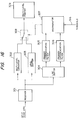
- Fig. 9 is a block diagram of processing for converting dither data into a PWM output signal 104a.
- Multi-level conversion of input digital image data (dither data 110) is performed by a multi-level processor 109, and density conversion is performed by the LUT 113.
- dither data indicates an image signal which has been subjected to dither processing (halftone processing) in a broad sense, as described above, and is normally a bi-level signal.
- bi-level conversion by a PWM (pulse-width modulation) method which has been filed by the present applicant (e.g., U.S.P. No. 765,938, filed on August 15, 1985 and the like) is adopted.
- Dither data (bi-level data) 110 which is data "0" or “1” is converted to 8-bit BCD indication multi-level data 109a by the multi-level processor 109 as follows: Data “0" ⁇ Data "0” Data “1” ⁇ Data "FF" Such conversion can be easily realized by, e.g., a ROM (Read-Only Memory).
- the 8-bit multi-level data 109a is input to the look-up table (LUT) 113 for density conversion, and is converted to the following 8-bit density correction data 113a.
- LUT look-up table
- the output signal 113a from the LUT 113 is converted to analog data by a digital-to-analog (D/A) converter 102, and each analog pixel data is sequentially input to one input terminal of a comparator 104 one by one.
- a pattern signal generator 103 generates a pattern signal 103a having a triangular waveform in a cycle corresponding to a predetermined number of pixels of the dither data 110, and the pattern signal 103a is input to the other input terminal of the comparator 104.
- the waveform of the pattern signal can be a sine waveform, sawtooth waveform, and the like.
- the pattern signal 103a preferably has the same cycle as the pixel width. However, for the sake of simplicity, the pattern signal 103a has a cycle corresponding to a three-pixel width, as shown in the timing chart of Fig. 10.
- An oscillator (master clock generator) 105 produces master clocks 105a.
- the master clocks 105a are counted down to a 1/4 cycle in synchronism with an H-SYNC signal 114 for each line generated from an H-SYNC generator 114 so as to be converted to pixel clocks 107a.
- the pixel clocks 107a are used as transfer clocks for image data, and latch timing clocks for the D/A converter 102.
- the H-SYNC signal can be internally generated or can be externally supplied. Since this embodiment is applied to the laser beam printer, the H-SYNC signal corresponds to a known beam detect (BD) signal.
- BD beam detect
- a timing signal generator 107 also produces screen clocks 107b.
- Each screen clock 107b has a cycle corresponding to an integer multiple of the master clock 105a.
- the screen clock 107b has a cycle three times that of the pixel clock 107a.
- the screen clocks 107b are input to the pattern signal generator 103.
- the pattern signal generator 103 comprises an integrator consisting of a capacitor, a resistor, and the like, and produces the pattern signal 103a of, e.g., a triangular waveform.
- the comparator 104 compares the levels of the analog image signal 102a and the pattern signal 103a, and outputs a PWM signal 104a.
- the PWM signal 104a is input to a modulator for modulating a laser beam (e.g., a laser driver 240 shown in Fig. 8 or 14).
- the laser beam is turned on or off in accordance with the pulse width, and a halftone image is formed on a recording medium (a photosensitive drum 135 in Fig. 14).
- the screen clocks 107b synchronous with the H-SYNC signal 114a are generated using the master clocks 105a which have a frequency (e.g., a frequency 12 times that of the triangular wave signal) higher than the frequency of the sync signal for generating a pattern signal (e.g., the triangular wave signal). Therefore, drift of the pattern (triangular wave) signals 103a generated from the pattern signal generator 103 (e.g., deviation between the pattern signals for first and second lines) can be 1/12 the pattern signal cycle. Therefore, since gradation information is pulse-width modulated using the pattern signals with less drift, a high-quality reproduced image can be obtained.
- a frequency e.g., a frequency 12 times that of the triangular wave signal
- drift of the pattern (triangular wave) signals 103a generated from the pattern signal generator 103 e.g., deviation between the pattern signals for first and second lines
- Fig. 10 is for explaining signal waveforms of the respective portion in the apparatus shown in Fig. 9.
- the master clocks 105a correspond to the outputs from the oscillator 105
- the BD signal 114a corresponds to the H-SYNC signal described above.
- the pixel clocks 107a are obtained by counting down the master clocks 105a from the oscillator 105 by the timing signal generator 107.
- the screen clocks 107b are obtained by the timing generator 107.
- the screen clocks 107b have a cycle corresponding to the total duration of three pixel clocks 107a.
- the screen clocks 107b are used for generating the pattern signal 103a, and are input to the pattern signal generator 103.
- the resultant multi-level data 109a is (FF) H (00) H (00) H (FF) H (FF) H .
- “( ) H " represents hexadecimal notation.
- the digital density correction data 113a is converted to data "BAABB” by the LUT 113 in accordance with the above-mentioned density conversion.
- Data "FF” ⁇ Data "B” The analog data 102a is image data which is D/A converted by the D/A converter 102. In this case, a high density value corresponds to data "B", and a low density value corresponds to data "A”. As shown in Fig. 10, the higher the analog level becomes, the higher the density becomes.
- the pattern signal 103a as the output from the pattern signal generator 103 has a triangular waveform, as indicated by the solid line of "INPUT TO COMPARATOR 104" in Fig. 10, and is compared with the analog data 102a.
- the comparison result is pulse-width modulated bi-level data, and is the PWM output signal 104a.
- the bi-level data 110 input to the image output device of this embodiment is subjectd to conversion processing to be converted to multi-level data.
- the multi-level data can be converted to a desired pulse width. Therefore, density control can be performed by the output device.
- the PWM output signal 104a drives the laser driver 240, and pulse-width modulates the semiconductor laser 131 to emit a laser beam.
- the laser beam emitted from the semiconductor laser 131 is collimated by the collimator lens 132, is deflected by a rotary multi-surface mirror 133, and is scanned on the photosensitive drum 135 by an f ⁇ lens 134.
- An optical image formed on the photosensitive drum forms an electrostatic latent image, and an image output is performed by a normal process of a copying machine.
- dither data is temporarily converted to analog image data, and thereafter, the analog image data is compared with the triangular wave pattern signal 103a having a predetermined cycle, thereby allowing variable pulse-width modulation. Therefore, an image output whose density can be controlled can be obtained.
- Fig. 11 shows the arrangement in which the present invention is applied to an image output system.
- Fig. 11 exemplifies a system for causing a plurality of printers (22A to 22D) to output an identical image in response to an output signal from a single controller (host computer) 21.
- the printers (22A to 22D) respectively comprise the above-mentioned image output devices.
- the controller 21 outputs identical dither data 110 to the printers.
- a density is controlled by, e.g., setting a potential on the photosensitive drum 135.
- the output densities of the printers can be controlled by setting or adjusting the LUT 113 shown in Fig. 9.
- the density control characteristics are selected by select dials 120 of the respective image output devices (22A to 22D) shown in Fig. 11.
- One of the density correction characteristics shown in Figs. 12 and 13 is selected by the select dial 120.
- the LUT 113 comprising, e.g., a ROM has a plurality of tables ( a to e ), as shown in Fig. 15.
- the table a is allocated from address (00) H to (FF) H
- the table b is allocated from address (100) H to (1FF) H
- the table c is allocated from address (200) H to (2FF) H
- the table d is allocated from address (300) H to (3FF) H
- Fig. 12 shows the density conversion characteristics obtained by the conversion tables of the LUT 113.
- the LUT 113 has conversion characteristics where the multi-level data 109a is plotted along the ordinate and the digital data 113a is plotted along the abscissa, as shown in Fig. 12. Referring back to Fig. 9, when an operator of the output devices (22A to 22D) operates the select dial 120 to select an appropriate density conversion characteristics, the select signal generator 115 produces the select signal 115a in accordance with the dial position. In Fig. 12, since five tables are provided, the select signal 115a can be a 3-bit signal.
- the LUT 113 receives the select signal as an upper address (an MSD address in Fig. 15), and the multi-level data 109a as a lower address, and outputs the digital data 113a in accordance with the table shown in Fig. 15. In this manner, when a desired curve is selected by the select dial of each printer, an output density can be maintained uniform.
- the circuit shown in Fig. 9 can process multi-level data input (three-level, four-level,).
- the multi-level processor 109 receives "0", "1/2", and "1" in the case of, e.g., three-level data, and converts them as follows: Input "0" ⁇ Output "00" Input "1/2" ⁇ Output "7F” Input "1” ⁇ Output "FF"
- the following processing can be performed in the same manner as in bi-level conversion.
- the LUT 113 can be linearly changed as shown in Fig. 12. Only intermediate data (corresponding to 1/2) of the multi-level data 109a can be converted. This can be realized by preparing an LUT shown in Fig. 13.
- Fig. 16 is a system block diagram of an image processing apparatus according to a fifth embodiment of the present invention.
- a receiver 301 receives pixel data (bi-level data) from an external device.
- a multi-level processor 302 converts input bi-level data (1-bit data) into 16 density levels (4-bit data) in the fifth embodiment, and outputs it.
- a level shifter 303 level-shifts the input bi-level data into a maximum density level or a minimum density level (both are 4-bit data) in a printer 309.
- a line buffer memory 304 can store several lines of input image data which is obtained through the receiver 301.
- Primary differentiation filters 305 and 306 calculate a feature amount of pixel of interest data from a plurality of pixel data around the pixel of interest data (in this embodiment, a matrix region of the pixel of interest data).
- a discriminator 307 discriminates, based on the feature amounts input from the primary differentiation filters 305 and 306, whether the input pixel of interest corresponds to halftone image information such as a photograph or unitone image data such as a character.
- the discriminator 307 outputs an instruction to a selector 308 in accordance with the discrimination result, thereby switching the selector 308.
- a multi-level printer 309 can perform gradation recording by one pixel.
- the multi-level processor 302 converts data of one pixel (pixel of interest) based on input bi-level data into multi-level data (e.g., four bits per pixel).
- multi-level data e.g., four bits per pixel.
- bi-level data adjacent to the central pixel in a 4 x 4 dot region are added to calculate an average density in this region, and the average density is assigned to the central pixel data (equation 1).
- the level shifter 303 converts bi-level data into the maximum or minimum density level of the multi-level printer.
- the outputs from the multi-level processor 302 and the level shifter 303 are switched by the selector 308.
- the selector 308 is controlled by the control signal from the discriminator 307, and the switched density level signal is output to the multi-level printer, thereby forming a visible image.
- the discrimination method of the discriminator 307 will be described below.
- Figs. 18a and 18b show the primary differentiation filters 305 and 306 used in this embodiment.
- Fig. 18a is used for vertical line detection
- Fig. 18b is used for horizontal line detection.
- Fig. 19a shows the effect of the primary differentiation filter on the dither halftone portion of a bi-level image.
- a mark “o” represents a "1" (black) dot. Pixels have one-to-one correspondence with minus and plus terms of the filter, and the absolute value of the primary differentiated value becomes zero.
- a dither halftone image in which a local change in density is small, a difference in the numbers of pixels corresponding to minus and plus terms is small, and as a result, the absolute value of the primary differentiated value is also small.
- Fig. 19b shows the effect of the primary differentiation filter in a line pattern and a character/symbol portion of a bi-level image.
- the difference in the numbers of pixels corresponding to the minus and plus terms of the filter becomes large, and hence, the absolute value of the primary differentiated value becomes large. Therefore, the primary differentiated value and an image have the following relationship.
- the bi-level image is a dither halfotne image.
- the bi-level image is a character or line pattern.
- Fig. 20 shows from which position image data is extracted for primary differentiation with reference to a hatched central pixel (pixel of interest) 310 (m,n).
- a hatched central pixel (pixel of interest) 310 m,n.
- 16 pixels are extracted from each of matrices A and B.
- 16 pixels are extracted from each of matrices C and D.
- a signal indicating that the selector 308 is switched to the level shifter 303 is supplied to a discriminated result port 317.
- the discriminated result corresponds to a line pattern.
- the multi-level processor 302 and the level shifter 303 each have line buffers to be synchronized with the discriminator 307. Instead, a common line buffer can be used.
- FIG. 22 A sixth embodiment for software processing will be described with reference to the flow chart shown in Fig. 22 and the block diagram shown in Fig. 23.
- a CPU 400 controls the entire apparatus.
- a ROM 401 stores the program corresponding to the flow chart shown in Fig. 22, and a RAM 402 is used for a work area of the CPU 400.
- Fig. 22 is the flow chart for switching processing of the selector 308 with respect to input image data. A description will be made with reference to this flow chart.
- step S1 the total number of "1"s in the matrices A, B, C, and D of input pixel data is counted. It is then discriminated in step S2 if pixel of interest data is a halftone image or a unitone image. In this case, one of the above-mentioned two methods is used as discrimination standard. If it is discriminated that the pixel of interest data is the halftone image, the flow advances to step S3, and an instruction for switching the selector 308 to the multi-level processor is output. Then, the flow returns to step S1. If it is discriminated in step S2 that the pixel of interest data is the unitone image, the flow advances to step S4, and an instruction for switching the selector 308 to the bi-level processor is output. Then, the flow returns to step S1. Thereafter, this processing is repeated, and the density levels of the pixel of interest data are sequentially output to the printer 309, thereby forming a visible image.
- image data when image data is output to an apparatus for forming a visible image after multi-level conversion, it is discriminated if the input image information is halftone image information or unitone image information such as a character/symbol and a line pattern, and image data suited for the respect image information is output. Therefore, a high-quality image can be formed.
- a 4 x 9 or 9 x 4 matrix is used for the description.
- the present invention is not limited to this.
- the receiver 1 receives image data through a communication line.
- the present invention can be applied to a case wherein an image is scanned by a CCD and the like.
- input image data is 1-bit bi-level data, but can be 2-bit three-level data.
Abstract
Description
- The present invention relates to an image processing apparatus for processing an image signal.
- In a conventional digital printer (bi-level printer), since an output is constituted by bi-level data corresponding to on/off of dots, input image data (8 bits) from an input system, e.g., a CCD, is bi-level processed by a dither method, and gradation of an original image is expressed by a matrix consisting of a plurality of pixels. However, in the dither method, a resolution is degraded if gradation is improved. For example, in order to reproduce 17 gray levels including white, a threshold value matrix consisting of 4 x 4 pixels is necessary, and in order to reproduce 65 gray levels, a threshold value matrix consisting of 8 x 8 pixels is necessary. Since an output image is represented in units of threshold value matrices, the resolution of a halftone image is degraded as the size of the threshold value matrix increases. When the systematic dither method is used, a threshold value is periodically repeated in units of threshold value matrices. For example, if a dot image is scanned, a difference between original image data and a threshold value periodically varies, and a low-frequency moiré pattern is formed in an output image resulting in a degraded image quality. An averaging error minimization method, wherein an error in an output pixel against original image data is compensated for the surrounding pixels so as to satisfactorily reproduce gradation of the original image data, has been proposed. This method is effective for eliminating moiré pattern. However, pixels are unnaturally connected, and a micro texture structure is formed, resulting in a poor reproduced image. This method is improved by a CAPIX method (General Meeting of Institute of Electronic Communication 5-212, 1985) having good character reproducibility. However, with this method, a micro texture structure is formed again. In the above-mentioned systematic dither method, an edge of the reproduced image, in particular, an inclined thin line, becomes a zigzag pattern.
- In the bi-level methods, original image data is compressed at high density in view of data volume. For example, if input image data has 8 bits per pixel, bi-level image data has 1 bit per pixel, resulting in 1/8 compression. Therefore, an image memory, an electronic file system, and the like for accumulating image data need only have a small capacity, and this is advantageous for communication for transferring image data. Thus, the above-mentioned techniques are indispensable for image processing.
- With recent improvements in a digital multi-level printer, an image having a higher quality than that obtainable with a conventional digital bi-level printer can be obtained. For this reason, image data which is once compressed to bi-level data by the conventional dither method must be recovered to multi-level data by multi-level processing.
- As described above, various methods for outputting an image including a halftone image by a digital printer have been proposed. Such methods include, e.g., the dither method, a density pattern method, and the like. These methods have the following advantages:
- (1) An image including a halftone image can be displayed using a bi-level display device.
- (2) The hardware arrangement of an apparatus is simple.
- (3) A satisfactory image quality can be obtained.
- Fig. 7A is for explaining the dither method. One
input pixel 28 is assigned to one component of thethreshold value matrix 25. Fig. 7B is for explaining the density pattern method. Oneinput pixel 28 is assigned to all the components of thethreshold value matrix 25. More specifically, in the density pattern method, one pixel of an input image is displayed by a plurality of cells on thedisplay screen 26. - The dither method and the density pattern method are not essentially different from each other, except that one input pixel is assigned to one or all the pixels of the threshold value matrix. Of course, an intermediate method therebetween is present. For example, a method in which one input pixel is assigned to a plurality of components (four (2 x 2) components in Fig. 7B) of the threshold value matrix, has been proposed. Therefore, no essential difference is present between the above methods, and the dither method, the density pattern method, and an intermediate method will be called a dither method.
- In the dither methods, since an image output is produced as bi-level data, it is constituted only by white or black, i.e., "0" or "1", and it is impossible to control the density of an image. However, various image output apparatuses, e.g., a laser beam printer, an ink-jet printer, a CRT device, and the like, are used. In this case, these output apparatuses respectively have their unique output characteristics, and an output density may often vary using the same bi-level signal.
- For example, in a laser beam printer, on/off operation of a laser beam onto a photosensitive drum is controlled so as to form an electrostatic latent image, and the latent image is developed, thereby obtaining a visible image. In this case, the potential of a latent image changes in accordance with an ON time of the laser beam. The ON time and the potential have a nonlinear relationship, and the potential and a developing density also have a nonlinear relationship. Since the laser beam printer alone poses such many variation factors, outputs from different output apparatuses vary widely, and an output reproduced image is often considerably different from an expected one using the same bi-level signal. In particular, this is prominent when an image data bi-level processing means is provided only to a controller (e.g., a host computer) outside the output apparatus, and a plurality of output apparatuses reproduce an image in response to the same bi-level signal from the controller. This applies not only to the bi-level image signal, but also to a multi-level signal, e.g., a four-level signal, received from the controller.
EP-A-024902 discloses apparatus and a method for converting one bit image data into a multi-level image data output which may be used in a subsequent printing process (which is not disclosed). It comprises parallel area integration and edge extraction filters, and an adder adding the two multi-bit outputs thereof to produce a multi-bit signal, which is then either halftone converted or used directly.
Various aspects of the present invention are concerned with:
providing an improved image processing apparatus;
providing an image processing apparatus which can provide a high-quality reproduced image;
providing an image processing apparatus which can provide a good reproduced image with a simple arrangement;
providing an image processing apparatus which reproduces a high-quality image using compressed pixel data;
providing an image processing apparatus which facilitates density control of a reproduced image;
providing an image processing apparatus which can accurately reproduce an original image;
providing an image output apparatus which can provide a high-quality reproduction output with a small data volume; and
providing an improved an image processing apparatus having an image identification function.
European Patent Specification No. EP-A-0,04,902 discloses one-bit pixel input data being converted into multi-bit per pixel output image data. However this specification is not concerned with matching image data processing to different image forming means.
In accordance with the invention there is provided apparatus for generating signals as set out inclaim 1.
There follows a description by way of example of various embodiments of the present invention, reference being made to the accompanying drawings. -
- Fig. 1 is a block diagram of an image processing apparatus according to a first embodiment of the present invention;
- Fig. 2 is a diagram schematically showing a laser printer to which the present invention can be applied;
- Fig. 3 is a detailed block diagram of a
multi-level processor 4; - Fig. 4 is a detailed block diagram of a
PWM circuit 5; - Fig. 5 is a timing chart for explaining signal waveforms of respective portions of the PWM circuit shown in Fig. 4;
- Fig. 6 is a view showing a second embodiment of the present invention;
- Figs. 7A and 7B are views for explaining the principle of the conventional dither method and density pattern method;
- Fig. 8 is a block diagram showing the basic arrangement according to a third embodiment of the present invention;
- Fig. 9 is a circuit diagram of the third embodiment;
- Fig. 10 is a timing chart for explaining the operation of the third embodiment;
- Fig. 11 is a block diagram of an image output system according to a fourth embodiment of the present invention;
- Figs. 12 and 13 are graphs showing a density conversion characteristic in the third embodiment;
- Fig. 14 is a diagram showing an output section of a laser beam printer according to the third embodiment;
- Fig. 15 is a memory map of a look-up table;
- Fig. 16 is a system block diagram of an image processing apparatus according to a fifth embodiment of the present invention;
- Figs. 17a to 17d are views for explaining the dither method and the multi-level method;
- Figs. 18a and 18b are views for explaining a primary differentiation filter;
- Figs. 19a and 19b are views for explaining the operation of the primary differentiation filter for a bi-level image;
- Fig. 20 is a view showing how image data is extracted for the primary differentiation;
- Fig. 21 is a view showing an internal arrangement of a discriminator;
- Fig. 22 is an operation flow chart of discrimination processing according to a sixth embodiment of the present invention; and
- Fig. 23 is a system block diagram of the sixth embodiment.
- Preferred embodiments of the present invention will now be described in detail with reference to the accompanying drawings.
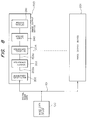
- Fig. 1 is a circuit diagram of an image processing apparatus according to a first embodiment of the present invention. Referring to Fig. 1, a digital data output device 1 A/D converts image data from a CCD sensor or a video camera (neither are shown), and outputs digital data of a predetermined number of bits (in this embodiment, 8 bits). A
bi-level processor 2 performs halftone processing for 8-bit pixel data output from theoutput device 1 using the systematic dither method or the average error minimization method, and compressed it to data having 1 bit per pixel. Amemory 3 comprising a RAM or an electronic file stores a predetermined volume of bi-level data (1-bit data) output from thebi-level processor 2. Amulti-level processor 4 converts the bi-level data output from thememory 3 into multi-level data having 8 bits per pixel. The multi-level data output from themulti-level processor 4 is input to a PWM (pulse width modulation)circuit 5. The operation of this embodiment will now be described. Data consisting of 8 bits per pixel output from theoutput device 1 is converted to bi-level data consisting of 1 bit per pixel, and is stored in thememory 3. - The bi-level data output from the
memory 3 is input to themulti-level processor 4, and is converted again to multi-level data consisting of 8 bits per pixel. The converted data is then transferred to thePWM circuit 5. - The
PWM circuit 5 performs pulse width modulation processing for the input 8-bit pixel data, and outputs it to a terminal 39 as a PWM signal. Note that numbers on respective lines in Fig. 1 represent the numbers of bits, and this also applies to Figs. 3, 4, and 6. - The
multi-level processor 4 will be described in more detail. Fig. 3 is a detailed block diagram of themulti-level processor 4. As shown in Fig. 3, bi-level data of "0" (white) or "1" (black), which is output from thememory 3 and is input to aterminal 6, is converted to 8-bit data by an 8-bit converter 7.
Data 0 →Data 00
Data 1 → Data FF
The converted 8-bit data is sequentially stored in abuffer memory 8 consisting of two lines (when one line is used for a write mode, the other one is used for a read mode) or several lines. The data stored in thebuffer memory 8 is read out and is subjected to spatial filter processing by a smoothingcircuit 9. As a spatial filter, a one-dimensional or two-dimensional spatial filter can be used, and a weighted averaging filter, a Gaussian filter, or a composite filter for averaging and edge emphasis is preferable. The spatial filter can be selected from a plurality of filters in accordance with image data to be processed. If bi-level data input to themulti-level processor 4 is obtained by various algorithms, one of several spatial filters can be appropriately selected, so that optimal multi-level data can be obtained from any bi-level data. - Multi-level data output from the smoothing
circuit 9 is input to thePWM circuit 5 through a terminal 10. - The
PWM circuit 5 will now be described in detail. Fig. 4 is a detailed block diagram of thePWM circuit 5. The multi-level data output from themulti-level processor 4 is converted to an analog signal by a digital-to-analog (D/A)converter 11, and each pixel data is sequentially input to one input terminal of acomparator 12. Apattern signal generator 13 produces atriangular wave signal 56 in a given cycle, e.g., for each predetermined number of pixels of the digital data, and inputs it to the other input terminal of thecomparator 12. - Master clocks 52 generated from an oscillator (master clock generator) 15 are counted down to, e.g., a 1/4 cycle by a
timing signal generator 14, so as to be converted to pixel clocks 51, in synchronism with an H-SYNC signal 55 which is generated from an H-SYNC signal generator 16 for each line. The pixel clocks 51 serve as transfer clocks of pixel data, and as latch timing clocks of the D/A converter 11. The image processing apparatus of this embodiment is applied to a laser beam printer. Therefore, the H-SYNC signal 55 corresponds to a known BD (beam detect) signal indicating a scan position of a beam. - The
comparator 12 compares levels of ananalog image signal 53 and thetriangular wave signal 56, and outputs aPWM signal 39. ThePWM signal 39 is input to a modulator (e.g., alaser driver 40 shown in Fig. 2). A laser beam is turned on or off in accordance with the pulse width, and a halftone image is formed on a recording medium (aphotosensitive drum 45 shown in Fig. 2). - Fig. 5 is a timing chart for explaining signal waveforms in the respective portion of the
multi-level processor 5 shown in Fig. 4. Referring to Fig. 5, the master clocks 52 correspond to outputs from theoscillator 15, and theBD signal 55 corresponds to the H-SYNC signal, as described above. The pixel clocks 51 are obtained by counting down the master clocks 52 by thetiming signal generator 14. More specifically, the pixel clocks 51 are obtained by counting down the master clocks 52 to a 1/4 cycle by thetiming signal generator 14 in synchronism with the H-SYNC signal. Screen clocks 54 are obtained by counting down the pixel clocks 51 to a 1/3 cycle by thetiming signal generator 14. More specifically, each screen clock has a cycle corresponding to the total duration of threepixel clocks 51, and is synchronous with the BD signal. The screen clocks 54 serve as a sync signal for generating thetriangular wave signal 56, and are input to apattern signal generator 13. Digital data input to the terminal 10 is multi-level (8-bit) data obtained by themulti-level processor 4. Ananalog video signal 53 is image data which is D/A converted by the D/A converter 11. As can be seen from Fig. 5, each pixel data of analog level is generated in synchronism with the pixel clocks 51. As shown in Fig. 5, the higher the analog level becomes, the higher the density becomes. - The
triangular wave signal 56 as the output from thepattern signal generator 13 is generated in synchronism with the screen clocks 54 as indicated by the solid line of "INPUT TOCOMPARATOR 12" in Fig. 5, and is input to thecomparator 12. The broken line in Fig. 5 indicates image data which is converted to analog image data by the D/A converter 11. This analog image data is compared with thetriangular wave signal 56 from thepattern signal generator 13 by thecomparator 12, and is converted to pulse-width modulated bi-level data, as indicated as thePWM output 39. - In signal processing in this embodiment, after the multi-level
digital data 10 is temporarily converted to analog image data, the image data is compared with thetriangular wave signal 56 having a predetermined cycle, thereby allowing almost continuous pulse-width modulation. Therefore, a high-gradation image output can be obtained. - According to this embodiment, the screen clocks 54 synchronous with the H-
SYNC signal 55 are generated using the master clocks 52 which have a frequency (e.g., afrequency 12 times that of the triangular wave signal) higher than the frequency of the sync signal for generating a pattern signal (e.g., the triangular wave signal). Therefore, drift of the pattern (triangular wave) signals 56 generated from the pattern signal generator 13 (e.g., deviation between the pattern signals for the first and second lines) can be 1/12 the pattern signal cycle. Therefore, since gradation information is pulse-width modulated using the pattern signals with less drift, a high-quality reproduced image can be obtained. - As described above, 8-bit multi-level image data is converted to bi-level data and is stored in the
memory 3, and 8-bit multi-level data is reproduced from the bi-level data read out from thememory 3 and is further pulse-width modulated. Thus, a high-quality reproduction output can be obtained using a small-capacity memory. - Fig. 2 schematically shows a laser beam printer to which the present invention can be applied. Referring to Fig. 2, a terminal 39 receives the PWM signal shown in Fig. 1. The PWM signal input to the terminal 39 is input to the
laser driver 40. Thelaser driver 40 drives asemiconductor laser 41 in accordance with the PWM signal, so as to modulate a beam. A light beam emitted from thesemiconductor laser 41 is collimated by acollimator lens 42, and is deflected by arotary polyhedral mirror 43. Then, the light beam is scanned on aphotosensitive drum 45 by means of anfθ lens 44. An optical image formed on thephotosensitive drum 45 forms an electrostatic latent image, and an image output is performed by a normal process as in a copying machine. Abeam detector 57 detects the scanning position of the light beam, and theBD signal 55 is formed based on the output from thebeam detector 57. - Fig. 6 is a block diagram of an image processing apparatus according to a second embodiment of the present invention. The same reference numerals in Fig. 6 denote the same parts as in Fig. 1, and a detailed description thereof will be omitted.
- Fig. 6 shows a case wherein image data is transferred through a communication line as in a facsimile system, and is output through a printer. Image data (8 bits output from a digital
data output device 1 is converted to bi-level data by abi-level processor 2, and is input to an encoder 17. The encoder 17 compresses the input bi-level data and transfers it onto acommunication line 18. The transferred data is converted to the bi-level data by adecoder 19 on the reception end, and is still converted to multi-level data (8 bits) by amulti-level processor 4. Thereafter, the multi-level data is converted to a substantially continuous PWM signal by aPWM circuit 5, as described above, and is output to a printer. With this arrangement, a data volume upon communication can be greatly reduced, and a high-resolution image signal can be transferred in a short period of time. On the reception end, the decoded bi-level data is converted to the multi-level data, and the multi-level data is output to the printer as the PWM signal. Therefore, a high-quality output can be obtained. - In this embodiment, bi-level data (1 bit) is converted to multi-level data (8 bits). However, three-level data (2 bits) can be converted to multi-level data (8 bits). In this case, data "0" (white), "1/2" (gray), and "1" (black) are respectively converted to data "00", "80", and "FF" by the
multi-level processor 4. In this case, the memory capacity is slightly increased. However, an output of higher quality can be obtained. - As described above, input image data of predetermined number of bits is converted to bi-level data so as to store it in a memory or to transfer it through a communication line. Thereafter, the bi-level data is converted to multi-level data of a predetermined number of bits so as to produce a PWM signal, thereby obtaining an image output. Therefore, the following effects can be obtained.
- 1. Even if a memory capacity and a data volume upon communication are small, a high-quality output can be obtained.
- 2. Data which is converted to bi-level data by various algorithms can be processed, and an output of higher quality can be obtained.
- A third embodiment of the present invention will now be described. Fig. 8 shows the basic arrangement of the third embodiment.
- An image output system including an image output device according to the third embodiment shown in Fig. 8 comprises an image data output device 100 for outputting
digital image data 101, and a plurality ofimage output devices 200,..., 201 which are connected to the image data output device 100, and output digital image data 100 as an image. Thedigital image data 101 is, for example, a bi-level signal. Each image output device has amulti-level converter 202 for converting thedigital image data 101 intomulti-level density data 202a, adensity converter 203 for density-converting themulti-level density data 202a, a bi-level converter 204, for converting density-convertedmulti-level density data 203a into bi-level data, and the like. Theimage output devices 200 can be different output devices such as a laser beam printer, an ink-jet printer, and the like. - With the above arrangement, even if the
digital image data 101 is a bi-level signal which cannot represent a gradation density by one pixel, it is converted to themulti-level density data 203a first and then to bi-level data by the bi-level converter 204. Therefore, if theoutput devices 200 are different output devices, density control is enabled in the output devices so as to obtain a desired final output density. - The
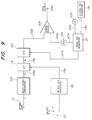
image output device 200 shown in Fig. 8 has the arrangement when the present invention is applied to a laser beam printer. As described above, after the inputdigital image data 101 is subjected to conversion processing, such as multi-level conversion, density conversion, bi-level conversion, and the like, its bi-level signal is input to alaser driver 240, and a laser beam is focused on a photosensitive drum through anoptical system 241. The multi-level conversion, density conversion, and the like will be described with reference to Figs. 9, 12, 13 and 15, and the bi-level conversion will be described with reference to Figs. 9 and 10. The optical system will be described with reference to Fig. 14. Note that themulti-level converter 202 shown in Fig. 8 corresponds to amulti-level processor 109 shown in Fig. 9, thedensity converter 203 corresponds to anLUT 113, and the bi-level converter 204 corresponds to a D/A converter 102, acomparator 104, and the like. Theoptical system 241 shown in Fig. 8 corresponds to asemiconductor laser 131, thecollimator lens 132, and the like shown in Fig. 14. - Fig. 9 is a block diagram of processing for converting dither data into a
PWM output signal 104a. Multi-level conversion of input digital image data (dither data 110) is performed by amulti-level processor 109, and density conversion is performed by theLUT 113. Note that dither data indicates an image signal which has been subjected to dither processing (halftone processing) in a broad sense, as described above, and is normally a bi-level signal. in this embodiment, bi-level conversion by a PWM (pulse-width modulation) method which has been filed by the present applicant (e.g., U.S.P. No. 765,938, filed on August 15, 1985 and the like) is adopted. - A description will be made with reference to Fig. 9. Dither data (bi-level data) 110 which is data "0" or "1" is converted to 8-bit BCD indication
multi-level data 109a by themulti-level processor 109 as follows:
Data "0"→ Data "0"
Data "1"→ Data "FF"
Such conversion can be easily realized by, e.g., a ROM (Read-Only Memory). Thereafter, the 8-bitmulti-level data 109a is input to the look-up table (LUT) 113 for density conversion, and is converted to the following 8-bitdensity correction data 113a. In this case, since the data indicate only two states of "00" and "FF", the data are converted to two arbitrary 8-bit data "A" and "B".
Data "00"→Data "A"
Data "FF"→Data "B"
Since thebi-level dither data 110 is converted to the multi-level data in this manner, density conversion, i.e., density control is enabled, and is performed by theLUT 113 in accordance with desired density conversion characteristics. As will be described later, the density conversion characteristics are as shown in Fig. 12 or 13. These characteristics are selected in accordance with a select signal 115a from aselect signal generator 115. Density conversion will be described later in more detail. - The
output signal 113a from theLUT 113 is converted to analog data by a digital-to-analog (D/A)converter 102, and each analog pixel data is sequentially input to one input terminal of acomparator 104 one by one. Apattern signal generator 103 generates apattern signal 103a having a triangular waveform in a cycle corresponding to a predetermined number of pixels of thedither data 110, and thepattern signal 103a is input to the other input terminal of thecomparator 104. The waveform of the pattern signal can be a sine waveform, sawtooth waveform, and the like. In the laser beam printer of this embodiment, thepattern signal 103a preferably has the same cycle as the pixel width. However, for the sake of simplicity, thepattern signal 103a has a cycle corresponding to a three-pixel width, as shown in the timing chart of Fig. 10. - The
pattern signal 103a input to thecomparator 104 will now be described. An oscillator (master clock generator) 105 producesmaster clocks 105a. Themaster clocks 105a are counted down to a 1/4 cycle in synchronism with an H-SYNC signal 114 for each line generated from an H-SYNC generator 114 so as to be converted topixel clocks 107a. Thepixel clocks 107a are used as transfer clocks for image data, and latch timing clocks for the D/A converter 102. Note that the H-SYNC signal can be internally generated or can be externally supplied. Since this embodiment is applied to the laser beam printer, the H-SYNC signal corresponds to a known beam detect (BD) signal. Atiming signal generator 107 also producesscreen clocks 107b. Eachscreen clock 107b has a cycle corresponding to an integer multiple of themaster clock 105a. In this embodiment, thescreen clock 107b has a cycle three times that of thepixel clock 107a. The screen clocks 107b are input to thepattern signal generator 103. Thepattern signal generator 103 comprises an integrator consisting of a capacitor, a resistor, and the like, and produces thepattern signal 103a of, e.g., a triangular waveform. - The
comparator 104 compares the levels of theanalog image signal 102a and thepattern signal 103a, and outputs aPWM signal 104a. ThePWM signal 104a is input to a modulator for modulating a laser beam (e.g., alaser driver 240 shown in Fig. 8 or 14). The laser beam is turned on or off in accordance with the pulse width, and a halftone image is formed on a recording medium (aphotosensitive drum 135 in Fig. 14). - In this embodiment, the screen clocks 107b synchronous with the H-
SYNC signal 114a are generated using themaster clocks 105a which have a frequency (e.g., afrequency 12 times that of the triangular wave signal) higher than the frequency of the sync signal for generating a pattern signal (e.g., the triangular wave signal). Therefore, drift of the pattern (triangular wave) signals 103a generated from the pattern signal generator 103 (e.g., deviation between the pattern signals for first and second lines) can be 1/12 the pattern signal cycle. Therefore, since gradation information is pulse-width modulated using the pattern signals with less drift, a high-quality reproduced image can be obtained. - Fig. 10 is for explaining signal waveforms of the respective portion in the apparatus shown in Fig. 9. Referring to Fig. 10, the
master clocks 105a correspond to the outputs from theoscillator 105, and theBD signal 114a corresponds to the H-SYNC signal described above. Thepixel clocks 107a are obtained by counting down themaster clocks 105a from theoscillator 105 by thetiming signal generator 107. The screen clocks 107b are obtained by thetiming generator 107. The screen clocks 107b have a cycle corresponding to the total duration of threepixel clocks 107a. The screen clocks 107b are used for generating thepattern signal 103a, and are input to thepattern signal generator 103. - Assume that data "10011" is input as the
dither data 110. By the multi-level conversion, the resultantmulti-level data 109a is (FF)H (00)H(00)H(FF)H(FF)H. Note that "( )H" represents hexadecimal notation. Then, the digitaldensity correction data 113a is converted to data "BAABB" by theLUT 113 in accordance with the above-mentioned density conversion.
Data "00"→ Data "A"
Data "FF"→ Data "B"
Theanalog data 102a is image data which is D/A converted by the D/A converter 102. In this case, a high density value corresponds to data "B", and a low density value corresponds to data "A". As shown in Fig. 10, the higher the analog level becomes, the higher the density becomes. - The
pattern signal 103a as the output from thepattern signal generator 103 has a triangular waveform, as indicated by the solid line of "INPUT TOCOMPARATOR 104" in Fig. 10, and is compared with theanalog data 102a. The comparison result is pulse-width modulated bi-level data, and is thePWM output signal 104a. - In this manner, the
bi-level data 110 input to the image output device of this embodiment is subjectd to conversion processing to be converted to multi-level data. After density correction, the multi-level data can be converted to a desired pulse width. Therefore, density control can be performed by the output device. - As shown in Fig. 14, the
PWM output signal 104a drives thelaser driver 240, and pulse-width modulates thesemiconductor laser 131 to emit a laser beam. The laser beam emitted from thesemiconductor laser 131 is collimated by thecollimator lens 132, is deflected by arotary multi-surface mirror 133, and is scanned on thephotosensitive drum 135 by an fθ lens 134. An optical image formed on the photosensitive drum forms an electrostatic latent image, and an image output is performed by a normal process of a copying machine. - In signal processing of this embodiment, dither data is temporarily converted to analog image data, and thereafter, the analog image data is compared with the triangular
wave pattern signal 103a having a predetermined cycle, thereby allowing variable pulse-width modulation. Therefore, an image output whose density can be controlled can be obtained. - Fig. 11 shows the arrangement in which the present invention is applied to an image output system. Fig. 11 exemplifies a system for causing a plurality of printers (22A to 22D) to output an identical image in response to an output signal from a single controller (host computer) 21. The printers (22A to 22D) respectively comprise the above-mentioned image output devices. The
controller 21 outputsidentical dither data 110 to the printers. In this case, there is a problem of different output densities of the printers. More specifically, if setting conditions of the respective printers are different, and a maximum density value Dmax is different for each printer, output image densities differ with respect to identical data. - In dither data itself, density control cannot be performed, and in a printer, a density is controlled by, e.g., setting a potential on the
photosensitive drum 135. However, in the embodiment shown in Fig. 11, the output densities of the printers can be controlled by setting or adjusting theLUT 113 shown in Fig. 9. The density control characteristics are selected byselect dials 120 of the respective image output devices (22A to 22D) shown in Fig. 11. One of the density correction characteristics shown in Figs. 12 and 13 is selected by theselect dial 120. - Each printer has a circuit as shown in Fig. 9. For example, the
LUT 113 comprising, e.g., a ROM has a plurality of tables (a to e), as shown in Fig. 15. In Fig. 15, the table a is allocated from address (00)H to (FF)H, the table b is allocated from address (100)H to (1FF)H, the table c is allocated from address (200)H to (2FF)H, and the table d is allocated from address (300)H to (3FF)H,.... Fig. 12 shows the density conversion characteristics obtained by the conversion tables of theLUT 113. TheLUT 113 has conversion characteristics where themulti-level data 109a is plotted along the ordinate and thedigital data 113a is plotted along the abscissa, as shown in Fig. 12. Referring back to Fig. 9, when an operator of the output devices (22A to 22D) operates theselect dial 120 to select an appropriate density conversion characteristics, theselect signal generator 115 produces the select signal 115a in accordance with the dial position. In Fig. 12, since five tables are provided, the select signal 115a can be a 3-bit signal. TheLUT 113 receives the select signal as an upper address (an MSD address in Fig. 15), and themulti-level data 109a as a lower address, and outputs thedigital data 113a in accordance with the table shown in Fig. 15. In this manner, when a desired curve is selected by the select dial of each printer, an output density can be maintained uniform. - In the above embodiment, the case of bi-level data input has been described. However, the circuit shown in Fig. 9 can process multi-level data input (three-level, four-level,...). In this case, the
multi-level processor 109 receives "0", "1/2", and "1" in the case of, e.g., three-level data, and converts them as follows:
Input "0"→ Output "00"
Input "1/2"→ Output "7F"
Input "1"→ Output "FF"
The following processing can be performed in the same manner as in bi-level conversion. TheLUT 113 can be linearly changed as shown in Fig. 12. Only intermediate data (corresponding to 1/2) of themulti-level data 109a can be converted. This can be realized by preparing an LUT shown in Fig. 13. - A fifth embodiment of the present invention will be described.
- Fig. 16 is a system block diagram of an image processing apparatus according to a fifth embodiment of the present invention.
- A
receiver 301 receives pixel data (bi-level data) from an external device. Amulti-level processor 302 converts input bi-level data (1-bit data) into 16 density levels (4-bit data) in the fifth embodiment, and outputs it. Alevel shifter 303 level-shifts the input bi-level data into a maximum density level or a minimum density level (both are 4-bit data) in aprinter 309. Aline buffer memory 304 can store several lines of input image data which is obtained through thereceiver 301. Primary differentiation filters 305 and 306 calculate a feature amount of pixel of interest data from a plurality of pixel data around the pixel of interest data (in this embodiment, a matrix region of the pixel of interest data). Adiscriminator 307 discriminates, based on the feature amounts input from the primary differentiation filters 305 and 306, whether the input pixel of interest corresponds to halftone image information such as a photograph or unitone image data such as a character. Thediscriminator 307 outputs an instruction to aselector 308 in accordance with the discrimination result, thereby switching theselector 308. Amulti-level printer 309 can perform gradation recording by one pixel. - The
multi-level processor 302 converts data of one pixel (pixel of interest) based on input bi-level data into multi-level data (e.g., four bits per pixel). In this embodiment, for data which is bi-level converted in accordance with a 4 x 4 dither matrix shown in Fig. 17a, bi-level data adjacent to the central pixel in a 4 x 4 dot region are added to calculate an average density in this region, and the average density is assigned to the central pixel data (equation 1).
- Therefore,

- For example, as shown in Fig. 17b, when pixel data of 4 x 4 dots including a pixel of interest is bi-level converted using the dither matrix shown in Fig. 17a, image data shown in Fig. 17c is obtained. When image data shown in Fig. 17c is input through the
receiver 301, the number of "1"s in Fig. 17c is counted (in this case, eight). Therefore, fromequation 1,
multi-level printer 309. This case is shown in Fig. 17d. - The
level shifter 303 converts bi-level data into the maximum or minimum density level of the multi-level printer. The outputs from themulti-level processor 302 and thelevel shifter 303 are switched by theselector 308. Theselector 308 is controlled by the control signal from thediscriminator 307, and the switched density level signal is output to the multi-level printer, thereby forming a visible image. - The discrimination method of the
discriminator 307 will be described below. - Figs. 18a and 18b show the primary differentiation filters 305 and 306 used in this embodiment. Fig. 18a is used for vertical line detection, and Fig. 18b is used for horizontal line detection. As the size of the primary differentiation filters 305 and 306, if a matrix of (2 x M + 1) x M in the vertical direction and M x (2 x M + 1) in the horizontal direction is selected, line pattern detection which is not easily affected by the dither pattern is enabled.
- Fig. 19a shows the effect of the primary differentiation filter on the dither halftone portion of a bi-level image. In Fig. 19, a mark "o" represents a "1" (black) dot. Pixels have one-to-one correspondence with minus and plus terms of the filter, and the absolute value of the primary differentiated value becomes zero. In a dither halftone image in which a local change in density is small, a difference in the numbers of pixels corresponding to minus and plus terms is small, and as a result, the absolute value of the primary differentiated value is also small.
- Fig. 19b shows the effect of the primary differentiation filter in a line pattern and a character/symbol portion of a bi-level image. The difference in the numbers of pixels corresponding to the minus and plus terms of the filter becomes large, and hence, the absolute value of the primary differentiated value becomes large. Therefore, the primary differentiated value and an image have the following relationship.
- When the absolute value of the primary differentiated value is small
it is discriminated that the bi-level image is a dither halfotne image. - When the absolute value of the primary differentiated value is large
it is discriminated that the bi-level image is a character or line pattern. - Fig. 20 shows from which position image data is extracted for primary differentiation with reference to a hatched central pixel (pixel of interest) 310 (m,n). As for the filter shown in Fig. 18a, 16 pixels are extracted from each of matrices A and B. As for the filter shown in Fig. 18b, 16 pixels are extracted from each of matrices C and D.
- As shown in Fig. 21, "1" pixels in pixel groups of the matrices A, B, C, and D are counted by adders 311a, 311b, 311c, and 311d. The count results of the matrices B and D are supplied respectively through
inverters absolute value converters comparator 315. For example, if either a vertical or horizontal line is detected, a signal indicating that theselector 308 is switched to thelevel shifter 303 is supplied to a discriminatedresult port 317. In a known method, if a larger one of the two absolute values is larger than a giventhreshold value 316, the discriminated result corresponds to a line pattern. - In another known method, if the sum of the two absolute values is larger than the
threshold value 316, a line pattern is determined. The selector shown in Fig. 16 is switched using this discriminated result. - The
multi-level processor 302 and thelevel shifter 303 each have line buffers to be synchronized with thediscriminator 307. Instead, a common line buffer can be used. - In the above description, hardware processing is made. A sixth embodiment for software processing will be described with reference to the flow chart shown in Fig. 22 and the block diagram shown in Fig. 23. In Fig. 22, a
CPU 400 controls the entire apparatus. AROM 401 stores the program corresponding to the flow chart shown in Fig. 22, and aRAM 402 is used for a work area of theCPU 400. - Fig. 22 is the flow chart for switching processing of the
selector 308 with respect to input image data. A description will be made with reference to this flow chart. - In step S1, the total number of "1"s in the matrices A, B, C, and D of input pixel data is counted. It is then discriminated in step S2 if pixel of interest data is a halftone image or a unitone image. In this case, one of the above-mentioned two methods is used as discrimination standard. If it is discriminated that the pixel of interest data is the halftone image, the flow advances to step S3, and an instruction for switching the
selector 308 to the multi-level processor is output. Then, the flow returns to step S1. If it is discriminated in step S2 that the pixel of interest data is the unitone image, the flow advances to step S4, and an instruction for switching theselector 308 to the bi-level processor is output. Then, the flow returns to step S1. Thereafter, this processing is repeated, and the density levels of the pixel of interest data are sequentially output to theprinter 309, thereby forming a visible image. - According to the present invention as described above, when image data is output to an apparatus for forming a visible image after multi-level conversion, it is discriminated if the input image information is halftone image information or unitone image information such as a character/symbol and a line pattern, and image data suited for the respect image information is output. Therefore, a high-quality image can be formed.
- In the above embodiments, a 4 x 9 or 9 x 4 matrix is used for the description. The present invention is not limited to this.
- In the above embodiments, the
receiver 1 receives image data through a communication line. However, the present invention can be applied to a case wherein an image is scanned by a CCD and the like. - In Figs. 16 and 23, input image data is 1-bit bi-level data, but can be 2-bit three-level data.
- The present invention is not limited to the above embodiments, and various other changes and modifications may be made within the spirit and scope of the appended claims.
Claims (20)
- An image processing apparatus comprising:
image data generation means for generating m-bit image data;
conversion means for converting the m-bit image data generated from said image data generation means into n-bit (n>m) image data; and
pulse-width modulation signal generation means for processing the n-bit image data output from said conversion means and generating a pulse-width modulation signal. - Apparatus according to claim 1, wherein said image data generation means has halftone processing means for halftone processing input image data and outputting the m-bit image data, and memory means for storing the m-bit image data output from said halftone processing means.
- Apparatus according to claim 1 or claim 2, wherein said image data generation means generates 1-bit image data.
- Apparatus according to any one of claims 1 to 3, wherein said conversion means has a converter for converting the m-bit image data generated from said image data generation means into the n-bit image data, and means for performing spatial filter processing with respect to the n-bit image data output from said converter.
- Apparatus according to any preceding claim, wherein said pulse-width modulation signal generation means processes the n-bit image data using a pattern signal of a predetermined cycle, and generates the pulse-width modulation signal.
- Apparatus according to claim 5, wherein said pattern signal is a triangular wave signal.
- Apparatus according to any one of claims 1 to 5 wherein said pulse-width modulation signal generation means has analog pattern signal generation means for generating substantially an analog pattern signal of a predetermined cycle, D/A conversion means for D/A converting the n-bit image data, and comparison means for comparing the analog pattern signal with an analog image signal output from said D/A conversion means and outputting the pulse-width modulation signal.
- Apparatus according to claim 7, further comprising means for modulating a beam based on the pulse-width modulation signal and reproducing an image, and means for generating a position signal indicating a scanning position of the beam, said analog pattern signal generation means generating the analog pattern signal in synchronism with the position signal.
- Apparatus according to any one of the preceding claims, wherein said conversion means includes density conversion means for performing density conversion of the n-bit image data.
- Apparatus according to claim 9, wherein said density conversion means has a plurality of tables used for density conversion, and any one of said plurality of tables is selectively used in accordance with a predetermined instruction signal.
- A method of processing an image comprising:
generating m-bit image data;
converting the m-bit image data so generated into n-bit (n>m) image data; and
processing the n-bit image data output from said conversion means to generate a pulse-width modulation signal. - A method according to claim 11, wherein generating the m-bit image data includes halftone processing input image data and storing the m-bit image data output from the halftone processing step.
- A method according to claim 11 or claim 12, wherein the generation of the m-bit image data generates 1-bit image data.
- A method according to any one of claims 11 to 13, wherein the converting of the m-bit image data into the n-bit image data includes performing spatial filter processing with respect to the converted n-bit image data.
- A method according to claim 1, wherein the generation of the pulse-width modulation signal involves processing the n-bit image data using a pattern signal of a predetermined cycle.
- A method according to claim 15, wherein said pattern signal is a triangular wave signal.
- A method according to any one of claims 11 to 15, wherein the generation of the pulse-width modulation signal comprises generating an analog pattern signal of a predetermined cycle, carrying out digital to analog conversion of the n-bit image data, comparing the analog pattern signal with an analog image signal output from said D/A conversion means, and outputting the pulse-width modulation signal as a result of the comparison.
- A method according to claim 17, further comprising modulating a beam based on the pulse-width modulation signal and reproducing an image, and generating a position signal indicating a scanning position of the beam, said analog pattern signal generation means generating the analog pattern signal in synchronism with the position signal.
- A method according to any one of claims 11 to 18 including performing density conversion on the n-bit image data.
- A method according to claim 19, wherein said density conversion is performed using a plurality of tables and any one of said plurality of tables is selectively used in accordance with a predetermined instruction signal.
Applications Claiming Priority (10)
| Application Number | Priority Date | Filing Date | Title |
|---|---|---|---|
| JP2907186 | 1986-02-14 | ||
| JP61029071A JP2555315B2 (en) | 1986-02-14 | 1986-02-14 | Image processing device |
| JP29071/86 | 1986-02-14 | ||
| JP49172/86 | 1986-03-06 | ||
| JP4917286 | 1986-03-06 | ||
| JP61049172A JPS62206965A (en) | 1986-03-06 | 1986-03-06 | Image processing device |
| JP61076680A JPH0834542B2 (en) | 1986-04-04 | 1986-04-04 | Image processing device |
| JP76680/86 | 1986-04-04 | ||
| JP7668086 | 1986-04-04 | ||
| EP87301187A EP0234809B1 (en) | 1986-02-14 | 1987-02-11 | Image processing apparatus |
Related Parent Applications (2)
| Application Number | Title | Priority Date | Filing Date |
|---|---|---|---|
| EP87301187A Division EP0234809B1 (en) | 1986-02-14 | 1987-02-11 | Image processing apparatus |
| EP87301187.8 Division | 1987-02-11 |
Publications (3)
| Publication Number | Publication Date |
|---|---|
| EP0717551A2 true EP0717551A2 (en) | 1996-06-19 |
| EP0717551A3 EP0717551A3 (en) | 1996-10-09 |
| EP0717551B1 EP0717551B1 (en) | 2000-05-17 |
Family
ID=27286413
Family Applications (3)
| Application Number | Title | Priority Date | Filing Date |
|---|---|---|---|
| EP96200452A Ceased EP0717550A3 (en) | 1986-02-14 | 1987-02-11 | Image processing apparatus |
| EP87301187A Expired - Lifetime EP0234809B1 (en) | 1986-02-14 | 1987-02-11 | Image processing apparatus |
| EP96200453A Expired - Lifetime EP0717551B1 (en) | 1986-02-14 | 1987-02-11 | Image processing apparatus |
Family Applications Before (2)
| Application Number | Title | Priority Date | Filing Date |
|---|---|---|---|
| EP96200452A Ceased EP0717550A3 (en) | 1986-02-14 | 1987-02-11 | Image processing apparatus |
| EP87301187A Expired - Lifetime EP0234809B1 (en) | 1986-02-14 | 1987-02-11 | Image processing apparatus |
Country Status (3)
| Country | Link |
|---|---|
| US (1) | US4926268A (en) |
| EP (3) | EP0717550A3 (en) |
| DE (2) | DE3752330T2 (en) |
Families Citing this family (52)
| Publication number | Priority date | Publication date | Assignee | Title |
|---|---|---|---|---|
| DE68927970T2 (en) * | 1988-09-08 | 1997-10-09 | Canon Kk | Point image data output device |
| DE69026159T2 (en) * | 1989-08-02 | 1996-10-17 | Canon Kk | Image processing device |
| EP0760578B1 (en) * | 1989-10-02 | 2003-04-02 | Canon Kabushiki Kaisha | Image forming apparatus and modulating method therein |
| US5210623A (en) * | 1989-12-21 | 1993-05-11 | Eastman Kodak Company | Apparatus and method for quantizing and/or reconstructing multi-dimensional digital image signals |
| DE69131260T2 (en) * | 1990-03-15 | 1999-11-04 | Canon Kk | Method and device for image communication |
| DE69123991T2 (en) * | 1990-03-23 | 1997-05-22 | Canon Kk | Image processing with a neural network |
| US6009193A (en) * | 1990-05-16 | 1999-12-28 | Canon Kabushiki Kaisha | Method and apparatus for converting N-value image to M-value image, for < NM |
| US5272544A (en) * | 1990-05-29 | 1993-12-21 | Canon Kabushiki Kaisha | Digital/analog converter and image processing apparatus using the same |
| US5563956A (en) * | 1990-08-30 | 1996-10-08 | Olympus Optical Co., Ltd. | Apparatus for filing data used for identifying an individual and for executing bi-level printing and multi-gradation printing on the basis of the data |
| US5680226A (en) * | 1990-10-10 | 1997-10-21 | Fuji Xerox Co., Ltd. | Image recording apparatus |
| US5404411A (en) * | 1990-12-27 | 1995-04-04 | Xerox Corporation | Bitmap-image pattern matching apparatus for correcting bitmap errors in a printing system |
| DE69124529T2 (en) * | 1991-01-10 | 1997-08-21 | Wang Laboratories | METHOD FOR TRANSFORMING A DITHER IMAGE |
| JPH04261264A (en) * | 1991-02-15 | 1992-09-17 | Victor Co Of Japan Ltd | Pulse width modulator |
| US5239597A (en) * | 1991-02-25 | 1993-08-24 | Samsung Electronics Co., Ltd. | Nearest neighbor dither image processing circuit |
| JPH04271564A (en) * | 1991-02-26 | 1992-09-28 | Fujitsu Ltd | Facsimile equipment |
| US5495341A (en) * | 1991-03-06 | 1996-02-27 | Canon Kabushiki Kaisha | Image processing apparatus which selects from one of plural generated clock counts |
| JPH04316276A (en) * | 1991-04-16 | 1992-11-06 | Ricoh Co Ltd | Image forming device |
| US5467422A (en) * | 1991-08-13 | 1995-11-14 | Konica Corporation | Image forming apparatus with neighboring pixel processing |
| DE69215038T2 (en) * | 1991-08-21 | 1997-04-10 | Konishiroku Photo Ind | Imaging device |
| US5241328A (en) * | 1991-09-20 | 1993-08-31 | Eastman Kodak Company | Apparatus and method for thermal printing of finely detailed images of photographic quality |
| US5673116A (en) * | 1991-10-03 | 1997-09-30 | Minolta Camera Kabushiki Kaisha | Image forming apparatus wherein data is converted between multi-level data and bi-level data |
| US5872636A (en) * | 1991-11-01 | 1999-02-16 | Canon Kabushiki Kaisha | Flexible resolution control and matching in image processing |
| JPH05284355A (en) * | 1992-04-02 | 1993-10-29 | Murata Mach Ltd | Contrast correction circuit for picture data |
| JPH0630272A (en) * | 1992-04-17 | 1994-02-04 | Canon Inc | Device and method for processing image |
| US5408329A (en) * | 1992-09-08 | 1995-04-18 | Xerox Corporation | Image enhancement through digital darkness control |
| NL9201570A (en) * | 1992-09-10 | 1994-04-05 | Oce Nederland Bv | Method for generating, per pixel, image information signals of a second type for obtaining image display signals, supplied by a first type and digital signal information generated by a first and a second signal source and using the information content regarding the density value contained in said signals, as well as a reproduction system for performing such a method. |
| JP2800592B2 (en) * | 1992-10-02 | 1998-09-21 | 村田機械株式会社 | Tool placement interference check method for machined figure data |
| US6501492B1 (en) * | 1992-11-13 | 2002-12-31 | Canon Kabushiki Kaisha | Image forming apparatus for outputting image in response to digital image signal |
| US5515180A (en) * | 1992-11-24 | 1996-05-07 | Sharp Kabushiki Kaisha | Image processing device |
| JP3040896B2 (en) * | 1993-06-16 | 2000-05-15 | シャープ株式会社 | Image processing device |
| US5479175A (en) * | 1993-09-10 | 1995-12-26 | Xerox Corporation | Method and apparatus for enhancing discharged area developed regions in a tri-level pringing system |
| US5581292A (en) * | 1993-09-10 | 1996-12-03 | Xerox Corporation | Method and apparatus for enhancing charged area developed regions in a tri-level printing system |
| US5504462A (en) * | 1993-09-10 | 1996-04-02 | Xerox Corporation | Apparatus for enhancing pixel addressability in a pulse width and position modulated system |
| US5471320A (en) * | 1994-05-11 | 1995-11-28 | Xerox Corporation | Stack filters for 1-to-N bit image processing in electronic printers |
| JP2820044B2 (en) * | 1994-10-28 | 1998-11-05 | 日本電気株式会社 | Image forming device |
| JPH08156329A (en) * | 1994-12-12 | 1996-06-18 | Fuji Xerox Co Ltd | Image forming device |
| JPH09150552A (en) * | 1995-11-30 | 1997-06-10 | Toshiba Corp | Image forming device |
| US6346998B2 (en) | 1996-11-20 | 2002-02-12 | Fuji Photo Film Co., Ltd. | Picture image outputting method and photograph finishing system using the method |
| CA2221658C (en) * | 1996-11-20 | 2005-03-22 | Fuji Photo Film Co., Ltd. | Picture image outputting method and photograph finishing system using the method |
| JPH114352A (en) * | 1997-06-12 | 1999-01-06 | Canon Inc | Image processing method, system and recording medium |
| US6975079B2 (en) * | 1997-08-26 | 2005-12-13 | Color Kinetics Incorporated | Systems and methods for controlling illumination sources |
| JPH11289454A (en) * | 1997-11-28 | 1999-10-19 | Canon Inc | Picture processing method, picture processor and storage medium storing computer readable program |
| US6347160B1 (en) * | 1998-01-30 | 2002-02-12 | Compaq Information Technologies Group, L.P. | Increasing the bit depth of and filtering dithered images for the purpose of inverse dithering |
| US6163629A (en) * | 1998-01-30 | 2000-12-19 | Compaq Computer Corporation | Method for low complexity low memory inverse dithering |
| US6222945B1 (en) * | 1998-01-30 | 2001-04-24 | Compaq Computer Corporation | Selective filtering of a dithered image for the purpose of inverse dithering |
| US6185334B1 (en) | 1998-01-30 | 2001-02-06 | Compaq Computer Corporation | Method for reconstructing a dithered image |
| US6590676B1 (en) * | 1999-05-18 | 2003-07-08 | Electronics For Imaging, Inc. | Image reconstruction architecture |
| JP4288398B2 (en) * | 2000-01-18 | 2009-07-01 | 株式会社ニコン | Image recording apparatus, image reproducing apparatus, and recording medium recording image processing program |
| JP2003179749A (en) * | 2001-12-11 | 2003-06-27 | Fujitsu Ltd | Data converting method |
| JP3840114B2 (en) * | 2002-01-22 | 2006-11-01 | キヤノン株式会社 | Controller unit operation verification system, controller device, image data output control method applied to controller device, program, and storage medium |
| JP4268026B2 (en) * | 2002-12-03 | 2009-05-27 | 株式会社リコー | Image forming apparatus |
| JP4821872B2 (en) | 2009-03-23 | 2011-11-24 | コニカミノルタビジネステクノロジーズ株式会社 | Image processing apparatus and image processing method |
Citations (5)
| Publication number | Priority date | Publication date | Assignee | Title |
|---|---|---|---|---|
| US3848087A (en) * | 1973-10-29 | 1974-11-12 | Rca Corp | Optical scanner control system |
| US4032977A (en) * | 1976-06-03 | 1977-06-28 | Xerox Corporation | Gray scale interpolation technique |
| EP0024902A2 (en) * | 1979-08-24 | 1981-03-11 | Xerox Corporation | Apparatus and method for converting one-bit image data into gray scale image data |
| EP0083176A2 (en) * | 1981-12-21 | 1983-07-06 | Image Resource Corporation | System and apparatus for the conversion of video signals into images on a light-responsive recording surface |
| US4541116A (en) * | 1984-02-27 | 1985-09-10 | Environmental Research Institute Of Mi | Neighborhood image processing stage for implementing filtering operations |
Family Cites Families (24)
| Publication number | Priority date | Publication date | Assignee | Title |
|---|---|---|---|---|
| US4004079A (en) * | 1975-11-14 | 1977-01-18 | Optronics International, Inc. | Method and apparatus for dual resolution photographic reproduction of line and continuous tone graphic materials |
| US4194221A (en) * | 1978-12-26 | 1980-03-18 | Xerox Corporation | Automatic multimode continuous halftone line copy reproduction |
| JPS5691585A (en) * | 1979-12-25 | 1981-07-24 | Fujitsu Ltd | Video signal processing method |
| JPS57159172A (en) * | 1981-03-24 | 1982-10-01 | Konishiroku Photo Ind Co Ltd | Image processor |
| JPS5811941A (en) * | 1981-07-16 | 1983-01-22 | Dainippon Screen Mfg Co Ltd | Processing method for picture pattern and character signals in mesh board picture recording device |
| JPS58200669A (en) * | 1982-05-18 | 1983-11-22 | Ricoh Co Ltd | Picture reader |
| JPS59223073A (en) * | 1983-06-01 | 1984-12-14 | Canon Inc | Picture processor |
| US4630125A (en) * | 1983-06-01 | 1986-12-16 | Xerox Corporation | Unscreening of stored digital halftone images |
| JPS60102060A (en) * | 1983-11-09 | 1985-06-06 | Hitachi Ltd | Picture binary-coding device |
| JPS60106269A (en) * | 1983-11-15 | 1985-06-11 | Ricoh Co Ltd | Transmission system for half-tone image |
| JPS60113582A (en) * | 1983-11-24 | 1985-06-20 | Ricoh Co Ltd | Processing method of half tone picture |
| JPS60160773A (en) * | 1984-02-01 | 1985-08-22 | Fuji Xerox Co Ltd | Picture reading transmission recording system |
| JPS6110360A (en) * | 1984-06-26 | 1986-01-17 | Canon Inc | Picture processing device |
| JPS6123468A (en) * | 1984-07-11 | 1986-01-31 | Nippon Telegr & Teleph Corp <Ntt> | Picture processor |
| US4638369A (en) * | 1984-09-04 | 1987-01-20 | Xerox Corporation | Edge extraction technique |
| US4800442A (en) * | 1985-08-15 | 1989-01-24 | Canon Kabushiki Kaisha | Apparatus for generating an image from a digital video signal |
| JPH067660B2 (en) * | 1985-08-29 | 1994-01-26 | キヤノン株式会社 | Optical beam scanning device |
| JP2647366B2 (en) * | 1985-08-29 | 1997-08-27 | キヤノン株式会社 | Image processing device |
| JPH0683358B2 (en) * | 1985-10-17 | 1994-10-19 | キヤノン株式会社 | Image information processing device adjustment method |
| US4803558A (en) * | 1985-11-15 | 1989-02-07 | Konishiroku Photo Industry Co., Ltd. | Halftone image estimation methods for dither images |
| DE3650773T2 (en) * | 1985-11-18 | 2002-12-05 | Canon Kk | Image forming apparatus |
| US4847695A (en) * | 1986-02-06 | 1989-07-11 | Canon Kabushiki Kaisha | Image processing apparatus in which the minimum and maximum widths of a pulse-width modulated signal can be independently adjusted in accordance with predetermined data signals |
| US4831392A (en) * | 1986-02-13 | 1989-05-16 | Canon Kabushiki Kaisha | Image processing apparatus using pulse width modulation with improved sensitivity |
| US4782398A (en) * | 1986-02-14 | 1988-11-01 | Canon Kabushiki Kaisha | Image processing apparatus |
-
1987
- 1987-02-11 EP EP96200452A patent/EP0717550A3/en not_active Ceased
- 1987-02-11 DE DE3752330T patent/DE3752330T2/en not_active Expired - Fee Related
- 1987-02-11 EP EP87301187A patent/EP0234809B1/en not_active Expired - Lifetime
- 1987-02-11 DE DE3752315T patent/DE3752315T2/en not_active Expired - Fee Related
- 1987-02-11 EP EP96200453A patent/EP0717551B1/en not_active Expired - Lifetime
-
1988
- 1988-12-12 US US07/282,896 patent/US4926268A/en not_active Expired - Lifetime
Patent Citations (5)
| Publication number | Priority date | Publication date | Assignee | Title |
|---|---|---|---|---|
| US3848087A (en) * | 1973-10-29 | 1974-11-12 | Rca Corp | Optical scanner control system |
| US4032977A (en) * | 1976-06-03 | 1977-06-28 | Xerox Corporation | Gray scale interpolation technique |
| EP0024902A2 (en) * | 1979-08-24 | 1981-03-11 | Xerox Corporation | Apparatus and method for converting one-bit image data into gray scale image data |
| EP0083176A2 (en) * | 1981-12-21 | 1983-07-06 | Image Resource Corporation | System and apparatus for the conversion of video signals into images on a light-responsive recording surface |
| US4541116A (en) * | 1984-02-27 | 1985-09-10 | Environmental Research Institute Of Mi | Neighborhood image processing stage for implementing filtering operations |
Non-Patent Citations (2)
| Title |
|---|
| IBM TECHNICAL DISCLOSURE BULLETIN, vol. 20, no. 1, 30 June 1977, NEW YORK (US), pages 31-32, XP002010717 A.L. MIX ET AL.: "Gray scale to pseudo halftone conversion" * |
| JOURNAL OF APPLIED PHOTOGRAPHIC ENGINEERING, vol. 7, no. 4, 31 August 1981, ROCHESTER (US), pages 111-114, XP002010718 YUH-JUH JUANG: "Design considerations for an intelligent high-speed image-scanning/recording system" * |
Also Published As
| Publication number | Publication date |
|---|---|
| DE3752330T2 (en) | 2001-10-31 |
| EP0717551A3 (en) | 1996-10-09 |
| DE3752330D1 (en) | 2001-06-21 |
| EP0234809B1 (en) | 2001-05-16 |
| EP0234809A3 (en) | 1989-03-29 |
| EP0717550A3 (en) | 1996-10-09 |
| EP0234809A2 (en) | 1987-09-02 |
| DE3752315D1 (en) | 2000-06-21 |
| US4926268A (en) | 1990-05-15 |
| EP0717551B1 (en) | 2000-05-17 |
| DE3752315T2 (en) | 2000-10-26 |
| EP0717550A2 (en) | 1996-06-19 |
Similar Documents
| Publication | Publication Date | Title |
|---|---|---|
| EP0717551B1 (en) | Image processing apparatus | |
| USRE38942E1 (en) | Apparatus for generating an image from a digital video signal | |
| US5513280A (en) | Discrimination of an edge portion of an image from a screen dot portion in an image processing system | |
| US5339171A (en) | Image processing apparatus especially suitable for producing smooth-edged output multi-level tone data having fewer levels than input multi-level tone data | |
| US4551768A (en) | Method and apparatus for processing image signal | |
| US4897734A (en) | Image processing apparatus | |
| JPH0787533B2 (en) | Image processing device | |
| EP0781034B1 (en) | Image processing apparatus and method | |
| US4811037A (en) | Image processing apparatus | |
| US6081349A (en) | Image processing device, image processing system, and method for generating screens for image processing | |
| CA1304520C (en) | Pulse width modulator for a printing apparatus | |
| EP0740459B1 (en) | Image processing method and apparatus | |
| US5506698A (en) | Image reproducing apparatus and process wherein minimized average error technique is used for each of fractions of original pel intensity value | |
| EP0514849B1 (en) | Image processing apparatus | |
| US5550955A (en) | Method and apparatus for digitally processing an image based on a random number and a multiplier corresponding to input image data | |
| US20030020935A1 (en) | Image processing method and apparatus | |
| JP2555315B2 (en) | Image processing device | |
| JPS59189782A (en) | Picture processing device | |
| JP2800071B2 (en) | Color image forming equipment | |
| JP3046034B2 (en) | Image forming device | |
| KR930007983B1 (en) | Middle tone picture processing system for fax | |
| JP2003305883A (en) | Imaging apparatus | |
| JPS61283272A (en) | Picture recorder | |
| JPH07104928B2 (en) | Image processing device | |
| JPH07104927B2 (en) | Image processing device |
Legal Events
| Date | Code | Title | Description |
|---|---|---|---|
| PUAI | Public reference made under article 153(3) epc to a published international application that has entered the european phase |
Free format text: ORIGINAL CODE: 0009012 |
|
| AC | Divisional application: reference to earlier application |
Ref document number: 234809 Country of ref document: EP |
|
| AK | Designated contracting states |
Kind code of ref document: A2 Designated state(s): DE GB NL |
|
| PUAL | Search report despatched |
Free format text: ORIGINAL CODE: 0009013 |
|
| AK | Designated contracting states |
Kind code of ref document: A3 Designated state(s): DE GB NL |
|
| 17P | Request for examination filed |
Effective date: 19970219 |
|
| 17Q | First examination report despatched |
Effective date: 19981020 |
|
| GRAG | Despatch of communication of intention to grant |
Free format text: ORIGINAL CODE: EPIDOS AGRA |
|
| GRAG | Despatch of communication of intention to grant |
Free format text: ORIGINAL CODE: EPIDOS AGRA |
|
| GRAH | Despatch of communication of intention to grant a patent |
Free format text: ORIGINAL CODE: EPIDOS IGRA |
|
| GRAH | Despatch of communication of intention to grant a patent |
Free format text: ORIGINAL CODE: EPIDOS IGRA |
|
| GRAA | (expected) grant |
Free format text: ORIGINAL CODE: 0009210 |
|
| AC | Divisional application: reference to earlier application |
Ref document number: 234809 Country of ref document: EP |
|
| AK | Designated contracting states |
Kind code of ref document: B1 Designated state(s): DE GB NL |
|
| REF | Corresponds to: |
Ref document number: 3752315 Country of ref document: DE Date of ref document: 20000621 |
|
| EN | Fr: translation not filed | ||
| PLBE | No opposition filed within time limit |
Free format text: ORIGINAL CODE: 0009261 |
|
| STAA | Information on the status of an ep patent application or granted ep patent |
Free format text: STATUS: NO OPPOSITION FILED WITHIN TIME LIMIT |
|
| 26N | No opposition filed | ||
| REG | Reference to a national code |
Ref country code: GB Ref legal event code: IF02 |
|
| PGFP | Annual fee paid to national office [announced via postgrant information from national office to epo] |
Ref country code: NL Payment date: 20030228 Year of fee payment: 17 |
|
| PGFP | Annual fee paid to national office [announced via postgrant information from national office to epo] |
Ref country code: GB Payment date: 20040128 Year of fee payment: 18 |
|
| PGFP | Annual fee paid to national office [announced via postgrant information from national office to epo] |
Ref country code: DE Payment date: 20040225 Year of fee payment: 18 |
|
| PG25 | Lapsed in a contracting state [announced via postgrant information from national office to epo] |
Ref country code: NL Free format text: LAPSE BECAUSE OF NON-PAYMENT OF DUE FEES Effective date: 20040901 |
|
| NLV4 | Nl: lapsed or anulled due to non-payment of the annual fee |
Effective date: 20040901 |
|
| PG25 | Lapsed in a contracting state [announced via postgrant information from national office to epo] |
Ref country code: GB Free format text: LAPSE BECAUSE OF NON-PAYMENT OF DUE FEES Effective date: 20050211 |
|
| PG25 | Lapsed in a contracting state [announced via postgrant information from national office to epo] |
Ref country code: DE Free format text: LAPSE BECAUSE OF NON-PAYMENT OF DUE FEES Effective date: 20050901 |
|
| GBPC | Gb: european patent ceased through non-payment of renewal fee |
Effective date: 20050211 |