EP0719674B2 - Vehicle instrumentation/console lighting assembly - Google Patents
Vehicle instrumentation/console lighting assembly Download PDFInfo
- Publication number
- EP0719674B2 EP0719674B2 EP95650048A EP95650048A EP0719674B2 EP 0719674 B2 EP0719674 B2 EP 0719674B2 EP 95650048 A EP95650048 A EP 95650048A EP 95650048 A EP95650048 A EP 95650048A EP 0719674 B2 EP0719674 B2 EP 0719674B2
- Authority
- EP
- European Patent Office
- Prior art keywords
- assembly
- light emitting
- emitting source
- vehicle
- mirror
- Prior art date
- Legal status (The legal status is an assumption and is not a legal conclusion. Google has not performed a legal analysis and makes no representation as to the accuracy of the status listed.)
- Expired - Lifetime
Links
- 238000005286 illumination Methods 0.000 claims description 34
- 230000004313 glare Effects 0.000 claims description 9
- 239000004065 semiconductor Substances 0.000 claims description 3
- 230000000712 assembly Effects 0.000 description 18
- 238000000429 assembly Methods 0.000 description 18
- 239000011521 glass Substances 0.000 description 13
- 239000000463 material Substances 0.000 description 9
- 239000010410 layer Substances 0.000 description 7
- 239000004033 plastic Substances 0.000 description 6
- 229920003023 plastic Polymers 0.000 description 6
- 238000000465 moulding Methods 0.000 description 5
- 239000003086 colorant Substances 0.000 description 4
- 230000002093 peripheral effect Effects 0.000 description 4
- 238000009423 ventilation Methods 0.000 description 4
- 239000004677 Nylon Substances 0.000 description 3
- 230000005540 biological transmission Effects 0.000 description 3
- 239000011248 coating agent Substances 0.000 description 3
- 238000000576 coating method Methods 0.000 description 3
- 238000010586 diagram Methods 0.000 description 3
- 238000005516 engineering process Methods 0.000 description 3
- 239000006260 foam Substances 0.000 description 3
- 229920001778 nylon Polymers 0.000 description 3
- 239000007787 solid Substances 0.000 description 3
- 229920001169 thermoplastic Polymers 0.000 description 3
- 229920001187 thermosetting polymer Polymers 0.000 description 3
- 239000004416 thermosoftening plastic Substances 0.000 description 3
- 238000002834 transmittance Methods 0.000 description 3
- 239000004743 Polypropylene Substances 0.000 description 2
- 229910001229 Pot metal Inorganic materials 0.000 description 2
- 229920000122 acrylonitrile butadiene styrene Polymers 0.000 description 2
- 239000000853 adhesive Substances 0.000 description 2
- 230000001070 adhesive effect Effects 0.000 description 2
- 230000008878 coupling Effects 0.000 description 2
- 238000010168 coupling process Methods 0.000 description 2
- 238000005859 coupling reaction Methods 0.000 description 2
- 238000009429 electrical wiring Methods 0.000 description 2
- 239000000835 fiber Substances 0.000 description 2
- 229910052751 metal Inorganic materials 0.000 description 2
- 239000002184 metal Substances 0.000 description 2
- 238000000034 method Methods 0.000 description 2
- 230000003287 optical effect Effects 0.000 description 2
- -1 polypropylene Polymers 0.000 description 2
- 229920001155 polypropylene Polymers 0.000 description 2
- 238000002310 reflectometry Methods 0.000 description 2
- 229910000838 Al alloy Inorganic materials 0.000 description 1
- 229910000980 Aluminium gallium arsenide Inorganic materials 0.000 description 1
- 229910005540 GaP Inorganic materials 0.000 description 1
- 229910001218 Gallium arsenide Inorganic materials 0.000 description 1
- 239000006096 absorbing agent Substances 0.000 description 1
- DHKHKXVYLBGOIT-UHFFFAOYSA-N acetaldehyde Diethyl Acetal Natural products CCOC(C)OCC DHKHKXVYLBGOIT-UHFFFAOYSA-N 0.000 description 1
- 125000002777 acetyl group Chemical class [H]C([H])([H])C(*)=O 0.000 description 1
- 239000012790 adhesive layer Substances 0.000 description 1
- AJGDITRVXRPLBY-UHFFFAOYSA-N aluminum indium Chemical compound [Al].[In] AJGDITRVXRPLBY-UHFFFAOYSA-N 0.000 description 1
- 238000004040 coloring Methods 0.000 description 1
- 239000004020 conductor Substances 0.000 description 1
- 238000010276 construction Methods 0.000 description 1
- 229920003020 cross-linked polyethylene Polymers 0.000 description 1
- 239000004703 cross-linked polyethylene Substances 0.000 description 1
- 230000005611 electricity Effects 0.000 description 1
- 239000006261 foam material Substances 0.000 description 1
- HZXMRANICFIONG-UHFFFAOYSA-N gallium phosphide Chemical compound [Ga]#P HZXMRANICFIONG-UHFFFAOYSA-N 0.000 description 1
- AMGQUBHHOARCQH-UHFFFAOYSA-N indium;oxotin Chemical compound [In].[Sn]=O AMGQUBHHOARCQH-UHFFFAOYSA-N 0.000 description 1
- 238000001746 injection moulding Methods 0.000 description 1
- 238000012423 maintenance Methods 0.000 description 1
- 238000004519 manufacturing process Methods 0.000 description 1
- 239000000203 mixture Substances 0.000 description 1
- 239000002991 molded plastic Substances 0.000 description 1
- 230000004297 night vision Effects 0.000 description 1
- 239000004417 polycarbonate Substances 0.000 description 1
- 229920000515 polycarbonate Polymers 0.000 description 1
- 230000005855 radiation Effects 0.000 description 1
- 230000000717 retained effect Effects 0.000 description 1
- 230000035939 shock Effects 0.000 description 1
- 239000004984 smart glass Substances 0.000 description 1
- 230000003595 spectral effect Effects 0.000 description 1
- 238000003860 storage Methods 0.000 description 1
- 239000000758 substrate Substances 0.000 description 1
- XOLBLPGZBRYERU-UHFFFAOYSA-N tin dioxide Chemical compound O=[Sn]=O XOLBLPGZBRYERU-UHFFFAOYSA-N 0.000 description 1
- 229910001887 tin oxide Inorganic materials 0.000 description 1
Images


Classifications
-
- B—PERFORMING OPERATIONS; TRANSPORTING
- B60—VEHICLES IN GENERAL
- B60Q—ARRANGEMENT OF SIGNALLING OR LIGHTING DEVICES, THE MOUNTING OR SUPPORTING THEREOF OR CIRCUITS THEREFOR, FOR VEHICLES IN GENERAL
- B60Q3/00—Arrangement of lighting devices for vehicle interiors; Lighting devices specially adapted for vehicle interiors
- B60Q3/80—Circuits; Control arrangements
-
- B—PERFORMING OPERATIONS; TRANSPORTING
- B60—VEHICLES IN GENERAL
- B60Q—ARRANGEMENT OF SIGNALLING OR LIGHTING DEVICES, THE MOUNTING OR SUPPORTING THEREOF OR CIRCUITS THEREFOR, FOR VEHICLES IN GENERAL
- B60Q3/00—Arrangement of lighting devices for vehicle interiors; Lighting devices specially adapted for vehicle interiors
- B60Q3/20—Arrangement of lighting devices for vehicle interiors; Lighting devices specially adapted for vehicle interiors for lighting specific fittings of passenger or driving compartments; mounted on specific fittings of passenger or driving compartments
- B60Q3/258—Rear-view mirrors
-
- B—PERFORMING OPERATIONS; TRANSPORTING
- B60—VEHICLES IN GENERAL
- B60Q—ARRANGEMENT OF SIGNALLING OR LIGHTING DEVICES, THE MOUNTING OR SUPPORTING THEREOF OR CIRCUITS THEREFOR, FOR VEHICLES IN GENERAL
- B60Q3/00—Arrangement of lighting devices for vehicle interiors; Lighting devices specially adapted for vehicle interiors
- B60Q3/80—Circuits; Control arrangements
- B60Q3/85—Circuits; Control arrangements for manual control of the light, e.g. of colour, orientation or intensity
-
- Y—GENERAL TAGGING OF NEW TECHNOLOGICAL DEVELOPMENTS; GENERAL TAGGING OF CROSS-SECTIONAL TECHNOLOGIES SPANNING OVER SEVERAL SECTIONS OF THE IPC; TECHNICAL SUBJECTS COVERED BY FORMER USPC CROSS-REFERENCE ART COLLECTIONS [XRACs] AND DIGESTS
- Y10—TECHNICAL SUBJECTS COVERED BY FORMER USPC
- Y10S—TECHNICAL SUBJECTS COVERED BY FORMER USPC CROSS-REFERENCE ART COLLECTIONS [XRACs] AND DIGESTS
- Y10S362/00—Illumination
- Y10S362/80—Light emitting diode
Definitions
- This invention relates to an assembly providing interior vehicle instrumentation and/or console lighting and, more particularly, to interior rearview mirror assemblies and interior lamp assemblies for vehicles which incorporate a low level light emitting source.
- Conventional lighting within vehicles includes general interior lighting for reading, entry of passengers at night and the like, as well as localized lighting for instrumentation and control switches.
- the former is typically provided by one or more lighting assemblies in the roof, header area, door panels or quarter window areas of the vehicle, while the latter is usually provided by means of individual light emitting sources at the rear of an instrument cluster or switch to provide back lighting visible from the front of the instrument or control.
- these conventional lighting sources fail to provide illumination of many other controls needed to fully operate the vehicle, leaving the driver or passenger to grope clumsily at night or in low light conditions to find items such as an ashtray, door handle, seat or window switch, heater control, cup holder, or the like.
- the person may switch on a general overhead light to find a particular control or handle but creating high levels of unwanted glare causing unsafe driving conditions for the vehicle driver.
- a conventional overhead or other general illumination light emitting source has typically included an incandescent bulb requiring high power levels and creating additional heat within the vehicle.
- incandescent light bulbs are also subject to short life spans and frequent failure. Consequently, incandescent light bulbs are usually a service item in the vehicle normally requiring service instruction to the dealership and/or consumer and spare part inventory by the vehicle manufacturer.
- use of such conventional lighting cannot be continuous during night vehicle use because of the high glare levels produced, thereby leaving many controls within the vehicle unidentified for most night driving or other low level light conditions.
- EP-B- 0 254 435 discloses a rearview mirror assembly according to the preamble of claim 1.
- United States Patent 4,580,196 provides general illumination compatible with the night vision capability of a pilot. There is no disclosure that the light source is mounted in a rearview mirror assembly, nor that it is positioned to direct the low level illumination to an instrument panel area or a console area of the vehicle.
- the rearview mirror assembly comprises a mirror case, a reflective mirror element within the case, a support for securing the assembly on a vehicle, and a mount receiving the light emitting source.
- the mount is on or within at least one of the mirror case and support.
- the light emitting source may optionally be mounted on either the mirror case or on the mirror support such as the mirror mounting arm. When on the mounting arm, the light emitting source may be positioned at the header area of the arm where it connects to the vehicle roof, or be separately mounted such as in an instrument housing/pod suspended from the mounting arm.
- the mirror case may also include at least one lamp, typically incandescent, providing general illumination within the vehicle for reading, courtesy lighting during passenger entry, or the like, which lamp may be separately switched from the low level light emitting source.
- the low level light emitting source avoids causing glare visible by the vehicle driver, and preferably provides illumination of less than about 60 lux, preferably less than about 25 lux, and most preferably less than about 10 lux at the locations desired to be illuminated.
- the light emitting source is a solid state source such as a light emitting diode although vacuum fluorescent sources, electroluminescent sources (including both organic electroluminescent sources and inorganic electroluminescent sources), and semiconductor laser sources may also be used.
- the preferred light emitting diode is preferably mounted in a hollow mounting adaptor telescopingly receiving the diode in one end and optionally being closed by a lens at the other end.
- the adaptor is preferably mounted in the bottom wall of the mirror case to the rear of the reflective rear element in a manner that avoids creation of unwanted glare.
- two or more of such low level light emitting sources may be incorporated in the mirror assembly at spaced locations for directing light at a desired or different portions of the vehicle interior, or may be grouped to provide more intense and/or broader area local illumination.
- the light emitting diode low level light emitting source provides a maximum illumination of about 0.2 to 4.0 lux at about 22 to 26 inches (56 to 66 cms) at about 20 mA to about 50 mA current, or less, and about 2.0 volts to about 5.0 volts, or less.
- the diode is typically connected in series with a suitable electrical resistor (typically less than about 1500 ohms and greater than about 100 ohms in electrical resistance; more preferably, less than about 1000 ohms and greater than about 200 ohms in resistance) to reduce the current to the diode and, preferably, to enable connection to an ignition voltage of the vehicle (typically 9 to 16 volts with about 12 volts nominal) and may be controlled by the ignition switch of the vehicle power system.
- a suitable electrical resistor typically less than about 1500 ohms and greater than about 100 ohms in electrical resistance; more preferably, less than about 1000 ohms and greater than about 200 ohms in resistance
- the assembly incorporating the low level light emitting source of the present invention provides numerous advantages over prior known vehicle instrumentation or control illumination sources.
- the present light emitting source may be directed to specific areas of instrumentation or control switches and can provide illumination of controls previously unlit such as shift levers, parking brake levers, ashtrays, cupholders, HVAC controls, radio knobs and the like.
- the light emitting source is small and compact in size and highly durable having a life span typically longer than the operational lifetime of the vehicle itself, and may be mounted in confined locations without concern for access for repair or replacement.
- the light emitting source preferably provides a defined pattern of light such as a cone of light which may be directed as desired without any separate reflector, separate lens, separate collimator, etc.; has low power consumption requirements and thus, is illuminated whenever the ignition switch of the vehicle is at the accessory on position or at the ignition on position, day and night; creates virtually no heat within the vehicle; and is amenable to mounting in many areas for illumination of desired controls. Moreover, the light emitting source avoids the creation of unwanted, unsafe glare which could otherwise distract or temporarily disable a vehicle driver.
- the light emitting source may also be used separately or together with other low level light emitting sources, can be used with virtually any mirror assembly and can be adjusted with the mirror case, or fixed in position on or within the mirror support such as on or within the mirror mounting arm or the coupling channel member.
- the light emitting source can also provide a variety of pleasing illumination colors without the need for separate coloring filters.
- FIGs. 1-7 illustrate a first embodiment 10 of an interior rearview mirror assembly of the present invention which incorporates a low level light emitting source adapted for centralized illumination of portions of a vehicle interior such as the instrumentation or controls in the instrument panel and/or console areas of a vehicle.
- console areas include floor consoles 121 (Fig. 2), shift lever consoles 125 (Figs. 2 and 10), instrument panel consoles 130 (Fig. 10), side door consoles 134 (Fig. 10), and, for light emitting sources mounted to direct light upwardly to the roof areas of the vehicle, header consoles 136 (Fig. 10) located such as in the headliner area and roof area such as above the front vehicle seats.
- the shift lever console 125 includes the gear shift or transmission selector lever including the PRND21 transmission selector indicator panel and, optionally, small part/coin storage bins, cup holders, ashtrays, control switches, etc. Such shift lever consoles are typically located in the floor centerline of the vehicle. However, on some vehicles, they may be mounted elsewhere such as on or about the steering column or off the instrument panel/front facia.
- Rearview mirror assembly 10 includes a support 80 for securing the mirror assembly to the vehicle on a windshield mounted member as shown in Figs. 5 and 14, or a mirror support arm 154 having a breakaway header bracket 158 secured to the roof area of the vehicle above the windshield as shown in Figs. 12 and 13.
- rearview mirror assembly 10 includes a directed, low level, non-incandescent light emitting source 90, preferably positioned on or within the mirror case or on or within the mirror support.
- mirror case 12 may also optionally include one or more lamp assemblies 24, 26 which provide separately switched, general illumination of the vehicle interior for reading, passenger entry, or the like.
- low level light emitting source 90 is controlled separately from the lamp assemblies 24, 26 by the vehicle ignition switch.
- Mirror assembly 10 includes a typically hollow mirror case 12 molded from resinous plastic material, preferably a fiber reinforced nylon plastic or an ABS plastic, or polypropylene, or other similar thermoplastic or thermoset material, and includes a similarly molded peripheral rim or bezel 12a also preferably formed from reinforced nylon or ABS plastic or polypropylene including spaced projections (not shown) snap-fitted into clips 14 integrally molded adjacent the periphery within case 12 (Fig. 4).
- Bezel 12a holds a prismatic, reflective rearview mirror element 16, preferably formed from transparent glass or resinous plastic material and having a reflective coating on its rear surface, fixed within the case.
- Mirror case 12 is preferably of the type described in United States Patent No.
- mirror case 12 includes a pair of lamp assemblies 24, 26 positioned on either side of actuator assembly 18 within compartments 25, 27 defined by walls 28, 30 molded on the interior of the back wall 13 of mirror case 12.
- the bottom portion 15 of the periphery of mirror case 12 includes a pair of light openings 32, 34, each light opening communicating with the respective compartment 25, 27 through which light from lamp assemblies 24-26 passes out of the mirror assembly.
- Lamp compartments 25, 27 also communicate respectively with a series of openings 36 and a series of openings 38 (Fig. 4) near the top wall 17 of the periphery of mirror case 12 thereby providing a ventilation path from opening 32 or 34 past each lamp assembly through each compartment.
- Lamp assemblies 24, 26 preferably include cartridge style, incandescent light bulbs 39 (Figs.
- Lenses 48, 50 are mounted in recessed openings 32, 34 to help direct light from lamp assemblies 24, 26 into the lap areas of the driver and passenger within the vehicle, respectively.
- Each lens defines a peripheral opening with the edge of its respective opening 32, 34 extending therearound to provide an entrance to the ventilation passageway allowing air to pass into compartments 25, 27.
- rear ventilation openings such as those shown at 52, 54 may be provided through rear wall 13 of mirror case 12 to provide additional ventilation of the compartments.
- lamp assemblies 24, 26 including bulbs 39 are connected to a source of electrical power in the vehicle electrical system by means of a wiring harness 60 including a connection block 62 mounted within mirror case 12 from which power from the vehicle electrical system is routed to the respective lamp assemblies 24, 26 by electrical wiring forming separate electrical circuits 64, 66.
- Connector block 62 is connected to the vehicle electrical system by a plug (not shown) received through an opening in back wall 13 of the mirror case.
- Each circuit includes a single pole, double-throw switch 68a, 68b for individual actuation of bulb 39 in lamp assembly 24 or 26 as desired.
- connection block 62 also provides a source of electrical power for a third electrical circuit 70 connected to the low power light emitting source 90.
- actuator assembly 18 includes a ball member 72 preferably formed from metal such as die-cast zinc, insert molded within toggle member 20 and projecting rearwardly through an opening in the back wall 13 of mirror case 12.
- Ball member 72 is connected to mirror support 80 including a pivotal, double ball joint mounting arm 82 which, in turn, is connected to a preferably die-cast zinc coupling channel member 84 adapted for attachment to a windshield mounted securing member as is conventionally known in the art.
- Channel member 84 is fixed with respect to the windshield wherein mirror case 12 and mounting arm 82 are moveable.
- Other forms of mirror supports may also be used such as single pivot mounting arms attached to the vehicle in the header roof area above the windshield as shown in Figs. 12 and 13 hereinafter, as well as other supports.
- the low level, directed, light emitting source 90 is mounted in interior rearview mirror assembly 10 so as to direct low level light through the bottom wall 15 of the mirror case.
- emitting sources may be used as light emitting source 90, including, but not limited to, very high intensity amber and reddish-orange light emitting diode (LED) sources, such as solid state light emitting diode LED sources utilizing double heterojunction AlGaAs/GaAs material technology, such as very high intensity red LED lamps T-1 3/4 (5mm) HLMP-4100/4101, available from Hewlett Packard Corporation, Palo Alto, California, or which use transparent substrate aluminum indium gallium phosphide (AlInGaP) material technology, commercially available from Hewlett Packard Corporation, Palo Alto, California under the designation T-1 3/4 (5mm) HLMT-DL00, HLMT-CH00, HLMT-CL00, HLMT-CH15, HLMT-CL15 and
- T-1 3/4 5mm
- Light emittance colors provided by such solid-state sources include orange, yellow, amber, red and reddish-orange, desirably without need of ancillary spectral filters.
- the preferred solid-state light emitting diodes operate at a forward voltage of about 2 volts to about 5 volts; have a luminous intensity (measured at the peak of the spacial radiation pattern which may not be aligned with the mechanical axis of the source package) of a minimum, at 20 mA current, of about 500 to about 5000 mcd (typical, about 700 to about 7000 mcd); operate at a forward current of about 20 mA to about 50 mA; emit with a dominant wavelength (CIE Chromaticity Diagram) of about 530 nm to about 680 nm; and have a viewing angle 2 ⁇ 1 ⁇ 2 (where ⁇ 1 ⁇ 2 is the off-axis angle where the luminous intensity is one half the peak intensity) of about 5 degrees to about 25 degrees.
- CIE Chromaticity Diagram
- vacuum fluorescent sources such as 12V battery driven, high luminance, vacuum fluorescent sources may be advantageously used. It may also be advantageous to use sources 90 which operate efficiently at about 12V or lower since these voltages are particularly amenable to motor vehicles. Also, ultrahigh luminance vacuum fluorescent sources, such as those suitable for heads-up-display applications in motor vehicles may be used with appropriate circuitry.
- Light emitting source 90 preferably produces a light level which, when measured at about 22 to 26 inches, (56 to 66 cms) is desirably less than about 60 lux, preferably less than about 25 lux, and most preferably less than about 10 lux, and has a low power consumption requiring a current less than about 200 mA, and preferably less than about 100 mA, and most preferably less than about 50 mA.
- non-LED, non- incandescent light emitting sources can be utilized such as electroluminescent sources, or semiconductor laser sources.
- the electroluminescent sources may be either inorganic or organic electroluminescent sources.
- Light emitting source 90 preferably has a well-defined light pattern, such as a cone of directed, low level light which eliminates the need for reflectors or other separate optical components to direct the light where desired, is preferably mounted on or within the mirror case 12, the mounting arm 82 or the channel member 84, and positioned to direct light at the desired area of the vehicle interior, e.g., the instrument panel or console area, and generates low heat while having an extremely long and durable life which typically will outlast the operational life of the rearview mirror assembly and the vehicle on which it is mounted. If mounted on or within channel member 84, light emitting source 90 may be fixed to illuminate a predetermined location within the interior cabin.
- a well-defined light pattern such as a cone of directed, low level light which eliminates the need for reflectors or other separate optical components to direct the light where desired, is preferably mounted on or within the mirror case 12, the mounting arm 82 or the channel member 84, and positioned to direct light at the desired area of the vehicle interior, e.g., the instrument panel or
- the small size of light emitting source 90 which preferably has a cross-sectional area less than about 4 cm2, and more preferably less than about 1 cm2, allows it to be easily positioned within the confined spaces of the rearview mirror assembly or interior lamp assembly. Because of their durability, these sources require little or no maintenance or repair thereby eliminating concern for access after mirror assembly 10 or an interior lamp assembly is manufactured.
- the preferred HLMT-DL00 diode from Hewlett Packard is available with a generally circular area of about 0.3 cm2 and requires only 20 mA current for operation and provides a 23° cone of directed light with a dominant amber color of a typical dominant wavelength of approximately 590 nm, and a typical intensity of 1500 millicandela (mcd).
- a resistor of about 450 ohms to about 500 ohms, typically about 470 ohms, is connected in series with the preferred LED, with the ignition/battery voltage of the vehicle being directly applied across their series connection.
- Other colors such as green, orange, yellow, red and blue may also be obtained depending on the elemental composition of the diode or other light emitting source selected. Separate filters are not required to produce the colors.
- the low level illumination provided by the light emitting diode 90 preferably has a maximum of about 0.2 to 4.0 lux at a distance of between about 22 and 26 inches (56 and 66 cms) at current of about 20 mA to about 50 mA at about 2.0 volts to about 5.0 volts.
- a resistor 92 is preferably connected in series with the light emitting diode to act as a voltage divider so as to reduce the ignition voltage of the vehicle, which is in the range of 9 to 16 volts (nominally 12 volts), to the desired operating voltage of the light source 90 (while typically is in the range of about 1 volt to about 5 volts, with about 2 volts to about 4.5 volts most typical for the preferred solid-state, very high intensity LED sources).
- Resistor 92 preferably has a resistance of less than about 1500 ohms and greater than about 100 ohms; more preferably less than about 1000 ohms and greater than about 200 ohms.
- the light emitting source such as source 90 (such as an LED) be mounted within one end of a hollow, molded plastic, cylindrical adaptor 94 having one open end 96 within the mirror case into which adapter the source is telescopically fitted and retained by friction or otherwise and a second opening 98 projecting through the bottom wall of mirror case 12.
- Opening 98 may optionally be closed by a clear plastic lens 100 which is snap-fitted between mounting ribs 99.
- Lens 100 may be any of a Fresnel lens, or a binary optic, or a refractive optic, or a holographic optic. Opening 98 helps confine and direct the pattern of light emanating from light source 90.
- Light source 90 may be mounted in a light conduit which may be formed separate from, or integral with (such as by molding during the molding of the case, or bezel of the case itself), the mirror case, mounting arm or channel member.
- the inner walls of this light conduit may optionally be coated with a diffuse and/or specularly reflecting material to provide a surface that enhances efficient illumination of interior vehicular locations.
- light directing means such as fiberoptic cables or bundles may optionally be used in conjunction with light source 90.
- the exterior surface of the lower end of adapter 94 includes spaced ridges 102a, 102b which receive the thickness of bottom wall 15 of mirror case 12 therebetween to stably support and position the adapter in the mirror case.
- the upper ridge 102a may include a tapered surface as does the upper end of adaptor 94 allowing the adapter to be pushed and snap-fitted into a circular opening in the bottom wall of the mirror case as shown in Fig. 6.
- hollow adapter 94 is molded from any thermoplastic resinous plastic although thermoset, resinous plastics could also be used.
- adapter 94 may be formed during the molding of the mirror case 12 itself and/or during molding of a subassembly of the mirror case, such as a bezel.
- Such molding may include insert injection molding whereby a diffuse and/or specularly reflecting surface or sleeve may be created across and along the inwardly facing surface of the inner walls of adapter 94.
- light emitting source such as diode 90 provides a directed pattern of light of low level intensity for illuminating the desired area of the vehicle such as the center console including the transmission shift lever (Fig. 2) without creating glare visible by the driver of the vehicle in which the assembly is mounted.
- the diode provides continuous illumination of the desired areas without requiring backlit, individual lighting on the instrumentation or controls, without generating significant heat, and without producing unwanted glare. As shown in Fig.
- light emitting diode 90 and resistor 92 may be connected in series in circuit 60 to the power system of the vehicle which includes a door operated switch 110 for alternate operation of lamp assemblies 24, 26 with manual switches 68a, 68b, and an ignition switch 112 which controls actuation of the diode.
- the vehicle power system is typically connected to a 12-volt DC battery, as illustrated.
- Light emitting diode 90 is operated by the closing of ignition switch 12 to either its accessory on or ignition on position and provides constant illumination of the desired instrument panel and/or console area of the vehicle interior at all times when the ignition switch is turned to the ignition on position or to the accessory on position.
- a second embodiment 120 of interior rearview mirror assembly may incorporate a pair of low level light emitting sources such as light emitting diodes 90', 90a' as described above in connection with assembly 10.
- Assembly 120 includes a mirror case 12', actuator assembly 18', lamp assemblies 24', 26' operated by switches 68a', 68b' all substantially similar to those described above in connection with assembly 10.
- assembly 120 includes two light emitting diodes 90', 90a' positioned at opposite ends of the mirror case as shown in Fig. 11.
- Each light emitting diode 90', 90a' is telescopingly mounted in a hollow, cylindrical adapter 94', 94a' as described above in connection with assembly 10 and as shown in Fig. 6.
- Diode 90' when mounted in its adapter 94', is directed to provide low level illumination of, for example, the center or shift lever console 125 and instrument panel areas of the vehicle while diode 90a' when mounted in its adapter 94a' is directed more sharply toward the instrument panel area 130 in front of the vehicle driver.
- a floor console is located at the position of the shift lever console, and the diode 90' will illuminate that console.
- various controls may be located in a console area on the side door such as at 134 in Fig.
- diode 90a' may be directed from mirror assembly 120 to illuminate such areas as well.
- one or more of the diodes could be mounted in case 120 and directed upwardly against a roof mounted header or headliner console as shown at 136 in Fig. 10.
- the positions of the light as directed by the diodes can, of course, be adjusted by moving the mirror assembly on its support.
- Each diode also includes an electrical resistor 92', 92a' connected in series therewith as described above in connection with assembly 10.
- diodes 90' and 90a' can both be connected in series with a common resistor, the ignition/battery voltage of the vehicle being applied across the series connection of the voltage dividing resistor and the two LED's.
- the diodes in assembly 120 are connected in parallel from connector block 62a such that both will provide directed low level light as controlled by the ignition switch 112. Accordingly, multiple low level light emitting sources can be incorporated in the interior rearview mirror assembly for directing low level illumination at desired, different areas of the vehicle interior. Alternately, multiple low level light emitting sources may be directed to illuminate the same target location in the vehicle to enhance intensity, uniformity and/or areal coverage of illumination.
- a third embodiment 150 of the present invention includes a low level light emitting source 152 as described above mounted in the mirror assembly support arm 154 at the header or roof area portion of the vehicle above the windshield.
- mirror support arm 154 is fixed in position and provides a single pivot for adjustment of the position of a rearview mirror assembly 156.
- Mirror assembly 156 may be any of a wide variety of interior rearview mirrors including manually operated, prismatic day/night mirrors as described in United States Patent Nos. 4,826,289 and 4,936,533 , electrically operated prismatic day/night mirrors such as described in United States Patent No. 4,948,242 , electrically operated, compass mirrors such as described in United States Patent No.
- the low light emitting sources are preferably used in conjunction with electrically operated mirrors as this provides a convenient and economical method to incorporate the sources in the vehicle at a central, high-mounted location, by piggy-back connection to the existing ignition power lines(s) that carry ignition voltage to the electrically operated mirror.
- Location on or within an interior rearview mirror, and particularly such that the low-level source is emitting downwardly such as through the bottom of the mirror case, is particularly advantageous in its placement of the emitting source below the driver's line of sight so that the driver is largely unaware and unglared by the emitting source mounted on or within the mirror case.
- Pivot 155 is located at that lower, free end 157 of rigid support arm 154 while the upper end of the arm includes a breakaway assembly 158 adapted to release from a header-mounted plate 160 upon impact during an accident or the like.
- Breakaway assembly 158 and support arm 154 may take one of several forms such as that shown in co-pending, European Patent Application No. 94650036.0 entitled MIRROR SUPPORT BRACKET, or in United States Patent No. 5,100,095 .
- low level light emitting source 152 is preferably a light emitting diode such as that described above in connection with assembly 10 and is fitted in a hollow, cylindrical adapter 162 similar to that in assembly 10 including circumferential ridges or ribs on the exterior adapted to mate with and fit along the edges of a circular aperture in the wall of the header end 158 of support arm 154.
- the electrical connections 164 from diode 152 extend through the plate 160 and the headliner/trim panel 166 along the roof of the vehicle for connection to the vehicle power system and ultimate control by the ignition switch. Accordingly, assembly 150 provides a fixed location for the low level light emitting source 152 allowing it to be directed at the desired interior instrument panel/console areas of the vehicle.
- a fourth embodiment of an interior rearview mirror assembly 180 includes an interior rearview mirror 182 of the type shown or described above in connection with embodiments 10, 120 or 150 or others as are conventionally known in the vehicle industry.
- Mirror assembly 182 is adjustably supported by a double ball pivot assembly 184 such as that shown at 82 above in assembly 10.
- the double ball pivot arm 184 is connected to a windshield mount by means of a coupler or channel-mount 186 such as that described above at 84 in connection with assembly 10.
- assembly 180 includes a separate instrument housing or pod 188 mounted on coupler 186 and including a low level light emitting source 190 projecting therefrom in a fixed position for illuminating a desired portion of the vehicle interior.
- Housing/pod 188 is preferably of the type shown and described in co-pending, European Patent Application No. 95650003.7 entitled VEHICLE INFORMATION DISPLAY.
- Such housing/pod may include displays such as compass, temperature and clock displays; sensors such as compass sensors, GPS sensors, automatic toll sensors, automatic headlamp dimmer sensors, and ambient light sensors; and lights such as incandescent lamps for general illumination within the vehicle.
- housing or pod 188 includes a two-part housing body including lower body 192 and upper body 194 joined by means of an interengaging rim or joint 196.
- Upper housing body 194 includes an attachment member 198 including a wall 200 defining a cavity 202 for receiving the coupler 186.
- Wall 200 has a low profile at one end 204 and increases in height to a taller end 206.
- Taller end 206 includes a circular recess or clip 208 while the shorter end 204 includes an inwardly projecting tab 210.
- Recess 208 has a diameter adapted to receive the neck portion 212 extending from a ball member included within mounting arm 184 in snap-fit fashion.
- Opposed shoulders 209, 211 at the top of the clip 208 form a partial circle with a neck receiving opening slightly smaller than the diameter of neck 212 and allow attachment member 198 to be detachably coupled to the neck. Simultaneously, tab 210 is received in a slot defined in the lower end of the coupler 186 prior to snap-fit of recess 208 around neck 212.
- housing/pod 188 may be secured to coupler 186 by other methods such as threaded fasteners, or the like.
- Housing/pod 188 also includes a plug receptacle or recess 214 for receiving an electrical plug to couple electrical energy and/or electrical signals to the instruments mounted within housing/pod 188 by means of a suitable pin connector/electrical plug (not shown).
- a pin receptacle 216 is mounted in the bottom of recess 214 and is connected to a circuit board 218 mounted on supports 220 within the housing to provide a digital display compass or the like for use on the vehicle.
- a low level light emitting source 190 preferably comprising a light emitting diode as described above in connection with assembly 10 is mounted in a fixed position, extends through the wall of lower housing 192 in a hollow, cylindrical adapter 222 as described above in connection with assemblies 10, 120 and 150.
- Diode 190 is connected by suitable electrical wiring 224 to pin receptacle 216 for connection via an electrical plug to the general vehicle electrical system.
- housing 188 may be secured to coupler 186 forming a part of the rearview mirror assembly support such that light emitting diode 190 is directed downwardly to provide low level illumination of a desired portion of the instrument panel or console area of the vehicle which is generally positioned below the rearview mirror assembly as shown by Figs. 2, 10 and 14.
- the operation of diode 190 is preferably controlled by the ignition switch of the vehicle.
- a low level light emitting source may be positioned in a separate housing secured to the rearview mirror assembly to provide greater flexibility in accommodating various types of rearview mirror assemblies and for different positioning options for illumination of various areas of the vehicle.
- Assembly 230 is of the type described in published European Patent Application No. 0 615 882 A2 .
- the assembly includes a mirror case 232 which, like mirror cases 12 and 12' above, is preferably molded from a resinous, thermoplastic or thermoset plastic which may be reinforced with fibers, adapted for mounting on a vehicle windshield by means of an adjustable mirror support 80' of the type described above in connection with assembly 10.
- mirror case 232 includes a socket 234 for receiving a ball member extending outwardly from mirror support 80', and is a rear wall 236, and a peripheral wall 238 having top, bottom and end portions. Socket 234 is formed in a recess 240 in the rear wall of the case, as shown in Fig. 18.
- the mirror case also includes a plurality of support flanges 242 integrally formed on the interior surface of the mirror case 232 to support a variable reflectance, electro-optic mirror cell 246 more fully described below.
- a forward facing light sensor (not shown) extends through rear wall 236 while a second light sensor 244 faces rearwardly.
- Electro-optic, reflective mirror cell 246 (which preferably is an electrochromic cell either of the solid-state type or the electrochemichromic type] is mounted in the rearwardly facing opening of mirror case 232 and held therein by a peripheral bezel 248 as shown in Fig. 18.
- a layer of foam material 250 is adhered to the rear surface of mirror cell 246 and covers substantially the entire rear surface of the cell except where items such as through-the-cell photodetectors and information displays, such as compass displays, are mounted behind the mirror.
- Foam layer 250 such as a cross-linked polyethylene foam, acts as a resilient shock absorber to reduce the risk of breaking the mirror element during an impact, and includes an adhesive layer applied to both its front and rear surfaces.
- Printed circuit board 252 includes a socket 254 on its rear surface for receiving a plug 256 extending from the vehicle electrical system through rear wall 236 at the upper portion of recess 240.
- Printed circuit board 252 also includes a two-position electrical switch 258 for on/off control of the electro-optic circuit.
- variable reflectance, electro-optic reflective mirror cell 246 is an electrochromic mirror cell that includes a transparent, front glass sheet 260 and a transparent, rear glass sheet 262 having a reflective coating 263 applied to its rear surface. Front glass 260 and reflective rear glass 262 are slightly offset relative to one another such that the upper and lower edges project for connection to appropriate metal connection strips (not shown). A variable light transmittance, electrochromic layer 264 is sandwiched in the space between the front glass 260 and rear of glass 262.
- the front surface of rear glass 262 and rear surface of front glass 260 each have a transparent electroconductive coating, such as indium tin oxide or doped tin oxide or the like, to conduct electricity across the full contact extent of electrochromic layer 264 from the connection strips secured at the offset top and bottom of the front and rear glass sheets.
- a transparent electroconductive coating such as indium tin oxide or doped tin oxide or the like
- electrical voltage is applied across electro-optic cell 246 between front glass 260 and rear glass 262 causing a variation in the transmittance of layer 264 such as darkening or opacity to reduce the light reflected by the reflective rear glass 262.
- Electrochromic layer 264 may, for example, be an electrochromic layer such as is described in United States Patent Nos.
- N.R. Lynam "Electrochromic Automotive Day/Night Mirrors", SAE Technical Paper Series, 870636 (1987); N.R. Lynam, “Smart Windows for Automobiles”, SAE Technical Paper Series, 900419 (1990); N.R. Lynam and A. Agrawal, "Automotive Applications of Chromogenic Materials”, Large Area Chromogenics: Materials and Devices for Transmittance Control, C.M. Lampert and C.G. Granquist, EDS., Optical Engineering Press, Washington (1990), or other as described above in assembly 10.
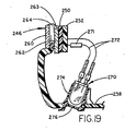
- a low level light emitting source 270 such as a light emitting diode as described above in connection with assemblies 10, 120, 150 and 180, and resistor 271 are connected to the vehicle electrical system through circuit board 252 by wire conductors 272 and frictionally telescoped into the top, open end of a hollow, cylindrical adapter 274 of the type described above in connection with the other embodiments of the present application.
- Adapter 274 includes an open lower end mounted in an aperture in the bottom periphery of case 232 through which low level light from light emitting source 270 is projected, such lower end optionally being closed by a suitable lens 276 as described in connection with the other embodiments above.
- low level light emitting source 270 may be fitted in the confines of a mirror case supporting an electro-optic mirror 246 as well as in mirror cases adapted to receive manual, day/night prismatic type reflective mirror elements or other electrically operated added features such as map or reading lights and compass displays.
Description
- This invention relates to an assembly providing interior vehicle instrumentation and/or console lighting and, more particularly, to interior rearview mirror assemblies and interior lamp assemblies for vehicles which incorporate a low level light emitting source.
- Conventional lighting within vehicles includes general interior lighting for reading, entry of passengers at night and the like, as well as localized lighting for instrumentation and control switches. The former is typically provided by one or more lighting assemblies in the roof, header area, door panels or quarter window areas of the vehicle, while the latter is usually provided by means of individual light emitting sources at the rear of an instrument cluster or switch to provide back lighting visible from the front of the instrument or control. However, these conventional lighting sources fail to provide illumination of many other controls needed to fully operate the vehicle, leaving the driver or passenger to grope clumsily at night or in low light conditions to find items such as an ashtray, door handle, seat or window switch, heater control, cup holder, or the like. Alternately, the person may switch on a general overhead light to find a particular control or handle but creating high levels of unwanted glare causing unsafe driving conditions for the vehicle driver. Use of such a conventional overhead or other general illumination light emitting source has typically included an incandescent bulb requiring high power levels and creating additional heat within the vehicle. Such incandescent light bulbs are also subject to short life spans and frequent failure. Consequently, incandescent light bulbs are usually a service item in the vehicle normally requiring service instruction to the dealership and/or consumer and spare part inventory by the vehicle manufacturer. Moreover, use of such conventional lighting cannot be continuous during night vehicle use because of the high glare levels produced, thereby leaving many controls within the vehicle unidentified for most night driving or other low level light conditions.
- Accordingly, there is a need for improved illumination of instrumentation, and console areas within a vehicle which would avoid production of unwanted, unsafe glare yet identify necessary vehicle controls without typical backlit instrumentation and electrical control switches.
EP-B- 0 254 435 discloses a rearview mirror assembly according to the preamble ofclaim 1. - This need is met by the invention claimed in
Claim 1. -
United States Patent 4,580,196 provides general illumination compatible with the night vision capability of a pilot. There is no disclosure that the light source is mounted in a rearview mirror assembly, nor that it is positioned to direct the low level illumination to an instrument panel area or a console area of the vehicle. - In one embodiment, the rearview mirror assembly comprises a mirror case, a reflective mirror element within the case, a support for securing the assembly on a vehicle, and a mount receiving the light emitting source. Preferably, the mount is on or within at least one of the mirror case and support. The light emitting source may optionally be mounted on either the mirror case or on the mirror support such as the mirror mounting arm. When on the mounting arm, the light emitting source may be positioned at the header area of the arm where it connects to the vehicle roof, or be separately mounted such as in an instrument housing/pod suspended from the mounting arm. The mirror case may also include at least one lamp, typically incandescent, providing general illumination within the vehicle for reading, courtesy lighting during passenger entry, or the like, which lamp may be separately switched from the low level light emitting source.
- The low level light emitting source avoids causing glare visible by the vehicle driver, and preferably provides illumination of less than about 60 lux, preferably less than about 25 lux, and most preferably less than about 10 lux at the locations desired to be illuminated. Preferably, the light emitting source is a solid state source such as a light emitting diode although vacuum fluorescent sources, electroluminescent sources (including both organic electroluminescent sources and inorganic electroluminescent sources), and semiconductor laser sources may also be used. The preferred light emitting diode is preferably mounted in a hollow mounting adaptor telescopingly receiving the diode in one end and optionally being closed by a lens at the other end. The adaptor is preferably mounted in the bottom wall of the mirror case to the rear of the reflective rear element in a manner that avoids creation of unwanted glare. If desired, two or more of such low level light emitting sources may be incorporated in the mirror assembly at spaced locations for directing light at a desired or different portions of the vehicle interior, or may be grouped to provide more intense and/or broader area local illumination.
- In the most preferred form, the light emitting diode low level light emitting source provides a maximum illumination of about 0.2 to 4.0 lux at about 22 to 26 inches (56 to 66 cms) at about 20 mA to about 50 mA current, or less, and about 2.0 volts to about 5.0 volts, or less. The diode is typically connected in series with a suitable electrical resistor (typically less than about 1500 ohms and greater than about 100 ohms in electrical resistance; more preferably, less than about 1000 ohms and greater than about 200 ohms in resistance) to reduce the current to the diode and, preferably, to enable connection to an ignition voltage of the vehicle (typically 9 to 16 volts with about 12 volts nominal) and may be controlled by the ignition switch of the vehicle power system.
- The assembly incorporating the low level light emitting source of the present invention provides numerous advantages over prior known vehicle instrumentation or control illumination sources. The present light emitting source may be directed to specific areas of instrumentation or control switches and can provide illumination of controls previously unlit such as shift levers, parking brake levers, ashtrays, cupholders, HVAC controls, radio knobs and the like. The light emitting source is small and compact in size and highly durable having a life span typically longer than the operational lifetime of the vehicle itself, and may be mounted in confined locations without concern for access for repair or replacement. The light emitting source preferably provides a defined pattern of light such as a cone of light which may be directed as desired without any separate reflector, separate lens, separate collimator, etc.; has low power consumption requirements and thus, is illuminated whenever the ignition switch of the vehicle is at the accessory on position or at the ignition on position, day and night; creates virtually no heat within the vehicle; and is amenable to mounting in many areas for illumination of desired controls. Moreover, the light emitting source avoids the creation of unwanted, unsafe glare which could otherwise distract or temporarily disable a vehicle driver. The light emitting source may also be used separately or together with other low level light emitting sources, can be used with virtually any mirror assembly and can be adjusted with the mirror case, or fixed in position on or within the mirror support such as on or within the mirror mounting arm or the coupling channel member. The light emitting source can also provide a variety of pleasing illumination colors without the need for separate coloring filters.
- Embodiments of the invention will now be described, by way of example, with reference to the accompanying drawings; in which:
- Fig. 1 is a front elevation of an interior rearview mirror assembly incorporating a low level light emitting source and Fig 8 shows the electrical circuit according to the present invention;
- Fig. 2 is a schematic illustration of a vehicle passenger compartment incorporating the rearview mirror assembly with low level light emitting source of Fig. 1 and illustrating illumination of the center console area of the passenger compartment;
- Fig. 3 is a bottom plan view of the rearview mirror assembly with low level light emitting source shown in Fig. 1;
- Fig. 4 is a front elevation of the interior of the rearview mirror assembly of Figs. 1 and 3 taken along plane IV-IV of Fig. 3 and illustrating the mounting of the low level light emitting source;
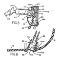
- Fig. 5 is a sectional side elevation of the interior rear view mirror assembly taken along plane V-V of Fig. 4;
- Fig. 6 is an enlarged, sectional elevation of area VI of Fig. 4 illustrating the mounting of the light emitting diode forming the low level light emitting source;
- Fig. 7 is an illustration of the wire harness providing the electrical circuit for the low level light emitting source and separate courtesy/reading map lights incorporated in the rearview mirror assembly of Figs. 1 and 3-5;
- Fig. 8 is a diagram of the electrical circuit for a vehicle incorporating the interior rearview mirror assembly of Figs. 1 and 3-5 illustrating control of the low level light emitting source via the vehicle ignition switch according to the invention;
- Fig. 9 is a diagram of a vehicle electrical system incorporating the interior rearview mirror assembly of Figs. 1 and 3-5 illustrating control of the low level light emitting source by a rheostat in the headlight control switch; not according to the invention
- Fig. 10 is a schematic illustration of a second embodiment of an interior rearview mirror assembly incorporating a pair of low level light emitting sources illuminating different areas of the vehicle interior;
- Fig. 11 is a front elevation of the interior of the rearview mirror assembly similar to Fig. 4 but incorporating two low level light emitting sources;
- Fig. 12 is a partially broken perspective view of a third embodiment of an interior rearview mirror assembly incorporating a low level light emitting source in the header mounting bracket of the rearview mirror mounting arm of the assembly;
- Fig. 13 is a side elevation of the rearview mirror assembly of Fig. 12 with portions broken away illustrating the mounting of the low level light emitting source in the header mounting bracket;
- Fig. 14 is a side elevation of a fourth embodiment of an interior rearview mirror assembly incorporating a low level light emitting source with the light emitting source mounted in a separate instrument housing/pod attached to the mirror support;
- Fig. 15 is a sectional view of the instrument housing/pod incorporating the low level light emitting source taken along plane XV-XV of Fig. 14;
- Fig. 16 is a plan view of the instrument housing/pod of Figs. 14 and 15;
- Fig. 17 is a perspective view of an alternate interior rearview mirror assembly incorporating a low level light emitting source, the reflective mirror element and retaining bezel being removed for viewing the internal construction of the assembly;
- Fig. 18 is a sectional, side elevation of the interior rearview mirror assembly of Fig. 17;
- Fig. 19 is an enlarged, sectional view of area XIX of Fig. 18 of the low level light emitting source mounted in the interior rearview mirror assembly;
- Referring now to the drawings in greater detail, Figs. 1-7 illustrate a
first embodiment 10 of an interior rearview mirror assembly of the present invention which incorporates a low level light emitting source adapted for centralized illumination of portions of a vehicle interior such as the instrumentation or controls in the instrument panel and/or console areas of a vehicle. Such console areas include floor consoles 121 (Fig. 2), shift lever consoles 125 (Figs. 2 and 10), instrument panel consoles 130 (Fig. 10), side door consoles 134 (Fig. 10), and, for light emitting sources mounted to direct light upwardly to the roof areas of the vehicle, header consoles 136 (Fig. 10) located such as in the headliner area and roof area such as above the front vehicle seats. Theshift lever console 125 includes the gear shift or transmission selector lever including the PRND21 transmission selector indicator panel and, optionally, small part/coin storage bins, cup holders, ashtrays, control switches, etc. Such shift lever consoles are typically located in the floor centerline of the vehicle. However, on some vehicles, they may be mounted elsewhere such as on or about the steering column or off the instrument panel/front facia.Rearview mirror assembly 10 includes asupport 80 for securing the mirror assembly to the vehicle on a windshield mounted member as shown in Figs. 5 and 14, or amirror support arm 154 having abreakaway header bracket 158 secured to the roof area of the vehicle above the windshield as shown in Figs. 12 and 13. As will be more fully explained hereinafter,rearview mirror assembly 10 includes a directed, low level, non-incandescentlight emitting source 90, preferably positioned on or within the mirror case or on or within the mirror support. In addition to low levellight emitting source 90,mirror case 12 may also optionally include one ormore lamp assemblies light emitting source 90 is controlled separately from thelamp assemblies -
Mirror assembly 10 includes a typicallyhollow mirror case 12 molded from resinous plastic material, preferably a fiber reinforced nylon plastic or an ABS plastic, or polypropylene, or other similar thermoplastic or thermoset material, and includes a similarly molded peripheral rim or bezel 12a also preferably formed from reinforced nylon or ABS plastic or polypropylene including spaced projections (not shown) snap-fitted intoclips 14 integrally molded adjacent the periphery within case 12 (Fig. 4). Bezel 12a holds a prismatic, reflectiverearview mirror element 16, preferably formed from transparent glass or resinous plastic material and having a reflective coating on its rear surface, fixed within the case.Mirror case 12 is preferably of the type described inUnited States Patent No. 5,178,448 , and includes an overcenter pivot type day/night actuator assembly 18 including atoggle member 20 preferably molded from reinforced nylon and apivot lever 22 preferably molded from acetal and of the type disclosed inU.S. Patent No. 5,327,288 . Movement ofpivot lever 22 between the two positions shown in Fig. 5 rotatesmirror case 12 including bezel 12a andreflective mirror element 16 aboutpivot axle 24 thereby changing the position of the prismatic mirror element from a high reflectivity day position in which incident light is reflected to the user's eyes from the highly reflective rear surface of theelement 16 to a reduced reflectivity, partial reflectance, night position in which a reduced amount of light incident on the mirror element is reflected from the front surface ofmirror element 16. - In addition,
mirror case 12 includes a pair oflamp assemblies actuator assembly 18 withincompartments walls back wall 13 ofmirror case 12. Thebottom portion 15 of the periphery ofmirror case 12 includes a pair oflight openings respective compartment openings 36 and a series of openings 38 (Fig. 4) near thetop wall 17 of the periphery ofmirror case 12 thereby providing a ventilation path from opening 32 or 34 past each lamp assembly through each compartment.Lamp assemblies style lamp holders respective compartments metallic reflectors light bulbs 39 and reflect light from those bulbs throughopenings Lamp assembly 24 is positioned to direct light throughopening 32 generally downwardly whileassembly 26 directs light downwardly and to the right from the position shown in Fig. 4.Lenses openings lamp assemblies respective opening compartments rear wall 13 ofmirror case 12 to provide additional ventilation of the compartments. - As shown in Figs. 4 and 7,
lamp assemblies bulbs 39 are connected to a source of electrical power in the vehicle electrical system by means of awiring harness 60 including aconnection block 62 mounted withinmirror case 12 from which power from the vehicle electrical system is routed to therespective lamp assemblies electrical circuits Connector block 62 is connected to the vehicle electrical system by a plug (not shown) received through an opening inback wall 13 of the mirror case. Each circuit includes a single pole, double-throw switch bulb 39 inlamp assembly connection block 62 also provides a source of electrical power for a thirdelectrical circuit 70 connected to the low powerlight emitting source 90. - As is best seen in Fig. 5,
actuator assembly 18 includes aball member 72 preferably formed from metal such as die-cast zinc, insert molded withintoggle member 20 and projecting rearwardly through an opening in theback wall 13 ofmirror case 12.Ball member 72 is connected to mirrorsupport 80 including a pivotal, double ball joint mountingarm 82 which, in turn, is connected to a preferably die-cast zinccoupling channel member 84 adapted for attachment to a windshield mounted securing member as is conventionally known in the art.Channel member 84 is fixed with respect to the windshield whereinmirror case 12 and mountingarm 82 are moveable. Other forms of mirror supports may also be used such as single pivot mounting arms attached to the vehicle in the header roof area above the windshield as shown in Figs. 12 and 13 hereinafter, as well as other supports. - As is also shown in Figs. 1 and 3-7, the low level, directed, light emitting
source 90 is mounted in interiorrearview mirror assembly 10 so as to direct low level light through thebottom wall 15 of the mirror case. A variety of emitting sources may be used as light emittingsource 90, including, but not limited to, very high intensity amber and reddish-orange light emitting diode (LED) sources, such as solid state light emitting diode LED sources utilizing double heterojunction AlGaAs/GaAs material technology, such as very high intensity red LED lamps T-1 3/4 (5mm) HLMP-4100/4101, available from Hewlett Packard Corporation, Palo Alto, California, or which use transparent substrate aluminum indium gallium phosphide (AlInGaP) material technology, commercially available from Hewlett Packard Corporation, Palo Alto, California under the designation T-1 3/4 (5mm) HLMT-DL00, HLMT-CH00, HLMT-CL00, HLMT-CH15, HLMT-CL15 and HLMT-DH00, or which use InGaAlP material technology available from Toshiba Corporation of Latham, New York, such as under the designation TLRH180D. Light emittance colors provided by such solid-state sources include orange, yellow, amber, red and reddish-orange, desirably without need of ancillary spectral filters. The preferred solid-state light emitting diodes, at 25°C or thereabouts, operate at a forward voltage of about 2 volts to about 5 volts; have a luminous intensity (measured at the peak of the spacial radiation pattern which may not be aligned with the mechanical axis of the source package) of a minimum, at 20 mA current, of about 500 to about 5000 mcd (typical, about 700 to about 7000 mcd); operate at a forward current of about 20 mA to about 50 mA; emit with a dominant wavelength (CIE Chromaticity Diagram) of about 530 nm to about 680 nm; and have a viewing angle 2θ½ (where θ½ is the off-axis angle where the luminous intensity is one half the peak intensity) of about 5 degrees to about 25 degrees. - Alternatively, vacuum fluorescent sources, such as 12V battery driven, high luminance, vacuum fluorescent sources may be advantageously used. It may also be advantageous to use
sources 90 which operate efficiently at about 12V or lower since these voltages are particularly amenable to motor vehicles. Also, ultrahigh luminance vacuum fluorescent sources, such as those suitable for heads-up-display applications in motor vehicles may be used with appropriate circuitry.Light emitting source 90 preferably produces a light level which, when measured at about 22 to 26 inches, (56 to 66 cms) is desirably less than about 60 lux, preferably less than about 25 lux, and most preferably less than about 10 lux, and has a low power consumption requiring a current less than about 200 mA, and preferably less than about 100 mA, and most preferably less than about 50 mA. Alternately, non-LED, non- incandescent light emitting sources can be utilized such as electroluminescent sources, or semiconductor laser sources. The electroluminescent sources may be either inorganic or organic electroluminescent sources.Light emitting source 90 preferably has a well-defined light pattern, such as a cone of directed, low level light which eliminates the need for reflectors or other separate optical components to direct the light where desired, is preferably mounted on or within themirror case 12, the mountingarm 82 or thechannel member 84, and positioned to direct light at the desired area of the vehicle interior, e.g., the instrument panel or console area, and generates low heat while having an extremely long and durable life which typically will outlast the operational life of the rearview mirror assembly and the vehicle on which it is mounted. If mounted on or withinchannel member 84, light emittingsource 90 may be fixed to illuminate a predetermined location within the interior cabin. The small size of light emittingsource 90, which preferably has a cross-sectional area less than about 4 cm2, and more preferably less than about 1 cm2, allows it to be easily positioned within the confined spaces of the rearview mirror assembly or interior lamp assembly. Because of their durability, these sources require little or no maintenance or repair thereby eliminating concern for access aftermirror assembly 10 or an interior lamp assembly is manufactured. The preferred HLMT-DL00 diode from Hewlett Packard is available with a generally circular area of about 0.3 cm2 and requires only 20 mA current for operation and provides a 23° cone of directed light with a dominant amber color of a typical dominant wavelength of approximately 590 nm, and a typical intensity of 1500 millicandela (mcd). Preferably, a resistor of about 450 ohms to about 500 ohms, typically about 470 ohms, is connected in series with the preferred LED, with the ignition/battery voltage of the vehicle being directly applied across their series connection. Other colors such as green, orange, yellow, red and blue may also be obtained depending on the elemental composition of the diode or other light emitting source selected. Separate filters are not required to produce the colors. The low level illumination provided by thelight emitting diode 90 preferably has a maximum of about 0.2 to 4.0 lux at a distance of between about 22 and 26 inches (56 and 66 cms) at current of about 20 mA to about 50 mA at about 2.0 volts to about 5.0 volts. Aresistor 92 is preferably connected in series with the light emitting diode to act as a voltage divider so as to reduce the ignition voltage of the vehicle, which is in the range of 9 to 16 volts (nominally 12 volts), to the desired operating voltage of the light source 90 (while typically is in the range of about 1 volt to about 5 volts, with about 2 volts to about 4.5 volts most typical for the preferred solid-state, very high intensity LED sources).Resistor 92 preferably has a resistance of less than about 1500 ohms and greater than about 100 ohms; more preferably less than about 1000 ohms and greater than about 200 ohms. - As is best seen in Fig. 6, it is preferred that the light emitting source such as source 90 (such as an LED) be mounted within one end of a hollow, molded plastic,
cylindrical adaptor 94 having oneopen end 96 within the mirror case into which adapter the source is telescopically fitted and retained by friction or otherwise and asecond opening 98 projecting through the bottom wall ofmirror case 12.Opening 98 may optionally be closed by a clearplastic lens 100 which is snap-fitted between mountingribs 99.Lens 100 may be any of a Fresnel lens, or a binary optic, or a refractive optic, or a holographic optic.Opening 98 helps confine and direct the pattern of light emanating fromlight source 90.Light source 90 may be mounted in a light conduit which may be formed separate from, or integral with (such as by molding during the molding of the case, or bezel of the case itself), the mirror case, mounting arm or channel member. The inner walls of this light conduit may optionally be coated with a diffuse and/or specularly reflecting material to provide a surface that enhances efficient illumination of interior vehicular locations. Also light directing means such as fiberoptic cables or bundles may optionally be used in conjunction withlight source 90. In addition, the exterior surface of the lower end ofadapter 94 includes spacedridges 102a, 102b which receive the thickness ofbottom wall 15 ofmirror case 12 therebetween to stably support and position the adapter in the mirror case. Theupper ridge 102a may include a tapered surface as does the upper end ofadaptor 94 allowing the adapter to be pushed and snap-fitted into a circular opening in the bottom wall of the mirror case as shown in Fig. 6. Preferably,hollow adapter 94 is molded from any thermoplastic resinous plastic although thermoset, resinous plastics could also be used. Also,adapter 94 may be formed during the molding of themirror case 12 itself and/or during molding of a subassembly of the mirror case, such as a bezel. Such molding may include insert injection molding whereby a diffuse and/or specularly reflecting surface or sleeve may be created across and along the inwardly facing surface of the inner walls ofadapter 94. - As shown in Fig. 7, when connected via
circuit 70 toconnector block 62 and the power system of the vehicle in which themirror assembly 10 is mounted, light emitting source such asdiode 90 provides a directed pattern of light of low level intensity for illuminating the desired area of the vehicle such as the center console including the transmission shift lever (Fig. 2) without creating glare visible by the driver of the vehicle in which the assembly is mounted. The diode provides continuous illumination of the desired areas without requiring backlit, individual lighting on the instrumentation or controls, without generating significant heat, and without producing unwanted glare. As shown in Fig. 8,light emitting diode 90 andresistor 92 may be connected in series incircuit 60 to the power system of the vehicle which includes a door operatedswitch 110 for alternate operation oflamp assemblies manual switches ignition switch 112 which controls actuation of the diode. The vehicle power system is typically connected to a 12-volt DC battery, as illustrated. Thus, in this circuit, if the door of the vehicle is opened as shown in Fig. 8, power will be directed to thegeneral illumination lamps 39 forming parts oflamp assemblies event switches lamps 39 will be lighted regardless of whether the vehicle door is opened or closed.Light emitting diode 90 is operated by the closing ofignition switch 12 to either its accessory on or ignition on position and provides constant illumination of the desired instrument panel and/or console area of the vehicle interior at all times when the ignition switch is turned to the ignition on position or to the accessory on position. - As shown in Figs. 10 and 11, a
second embodiment 120 of interior rearview mirror assembly may incorporate a pair of low level light emitting sources such as light emitting diodes 90', 90a' as described above in connection withassembly 10.Assembly 120 includes a mirror case 12', actuator assembly 18', lamp assemblies 24', 26' operated byswitches 68a', 68b' all substantially similar to those described above in connection withassembly 10. Instead of a singlelight emitting source 90, however,assembly 120 includes two light emitting diodes 90', 90a' positioned at opposite ends of the mirror case as shown in Fig. 11. Each light emitting diode 90', 90a' is telescopingly mounted in a hollow, cylindrical adapter 94', 94a' as described above in connection withassembly 10 and as shown in Fig. 6. Diode 90', when mounted in its adapter 94', is directed to provide low level illumination of, for example, the center orshift lever console 125 and instrument panel areas of the vehicle while diode 90a' when mounted in its adapter 94a' is directed more sharply toward theinstrument panel area 130 in front of the vehicle driver. In some vehicles, a floor console is located at the position of the shift lever console, and the diode 90' will illuminate that console. Also, various controls may be located in a console area on the side door such as at 134 in Fig. 10 and diode 90a' may be directed frommirror assembly 120 to illuminate such areas as well. Alternately, one or more of the diodes could be mounted incase 120 and directed upwardly against a roof mounted header or headliner console as shown at 136 in Fig. 10. The positions of the light as directed by the diodes can, of course, be adjusted by moving the mirror assembly on its support. Each diode also includes an electrical resistor 92', 92a' connected in series therewith as described above in connection withassembly 10. Alternately, diodes 90' and 90a' can both be connected in series with a common resistor, the ignition/battery voltage of the vehicle being applied across the series connection of the voltage dividing resistor and the two LED's. The diodes inassembly 120 are connected in parallel from connector block 62a such that both will provide directed low level light as controlled by theignition switch 112. Accordingly, multiple low level light emitting sources can be incorporated in the interior rearview mirror assembly for directing low level illumination at desired, different areas of the vehicle interior. Alternately, multiple low level light emitting sources may be directed to illuminate the same target location in the vehicle to enhance intensity, uniformity and/or areal coverage of illumination. - As shown in Figs. 12 and 13, a
third embodiment 150 of the present invention includes a low levellight emitting source 152 as described above mounted in the mirrorassembly support arm 154 at the header or roof area portion of the vehicle above the windshield. In this version,mirror support arm 154 is fixed in position and provides a single pivot for adjustment of the position of arearview mirror assembly 156.Mirror assembly 156 may be any of a wide variety of interior rearview mirrors including manually operated, prismatic day/night mirrors as described inUnited States Patent Nos. 4,826,289 and4,936,533 , electrically operated prismatic day/night mirrors such as described inUnited States Patent No. 4,948,242 , electrically operated, compass mirrors such as described inUnited States Patent No. 5,253,109 , electrically operated, interior rearview mirrors incorporating map/reading lights such as those described above inassemblies United States Patent Nos. 4,646,210 ,4,733,336 ,4,807,096 and5,178,448 , as well as electrically operated, automatically dimming mirrors as described inUnited States Patent Nos. 4,793,690 ,4,799,768 ,4,886,960 and5,193,029 , preferably electrochromic mirrors utilizing either solid state elements or electrochemichromic elements such as described in U.K. Patent Application No.9519958.4 Pivot 155 is located at that lower,free end 157 ofrigid support arm 154 while the upper end of the arm includes abreakaway assembly 158 adapted to release from a header-mountedplate 160 upon impact during an accident or the like.Breakaway assembly 158 andsupport arm 154 may take one of several forms such as that shown in co-pending,European Patent Application No. 94650036.0 United States Patent No. 5,100,095 . - As shown in Fig. 13, low level
light emitting source 152 is preferably a light emitting diode such as that described above in connection withassembly 10 and is fitted in a hollow,cylindrical adapter 162 similar to that inassembly 10 including circumferential ridges or ribs on the exterior adapted to mate with and fit along the edges of a circular aperture in the wall of theheader end 158 ofsupport arm 154. Theelectrical connections 164 fromdiode 152 extend through theplate 160 and the headliner/trim panel 166 along the roof of the vehicle for connection to the vehicle power system and ultimate control by the ignition switch. Accordingly,assembly 150 provides a fixed location for the low levellight emitting source 152 allowing it to be directed at the desired interior instrument panel/console areas of the vehicle. - With reference to Figs. 14-16, a fourth embodiment of an interior
rearview mirror assembly 180 includes an interiorrearview mirror 182 of the type shown or described above in connection withembodiments Mirror assembly 182 is adjustably supported by a doubleball pivot assembly 184 such as that shown at 82 above inassembly 10. The doubleball pivot arm 184 is connected to a windshield mount by means of a coupler or channel-mount 186 such as that described above at 84 in connection withassembly 10. Instead of mounting the low level light emitting source on the mirror assembly or the mounting arm for the mirror assembly, however,assembly 180 includes a separate instrument housing orpod 188 mounted oncoupler 186 and including a low levellight emitting source 190 projecting therefrom in a fixed position for illuminating a desired portion of the vehicle interior. Housing/pod 188 is preferably of the type shown and described in co-pending,European Patent Application No. 95650003.7 - As shown in Figs. 14-16, housing or
pod 188 includes a two-part housing body includinglower body 192 andupper body 194 joined by means of an interengaging rim or joint 196.Upper housing body 194 includes anattachment member 198 including awall 200 defining acavity 202 for receiving thecoupler 186.Wall 200 has a low profile at oneend 204 and increases in height to ataller end 206.Taller end 206 includes a circular recess or clip 208 while theshorter end 204 includes an inwardly projecting tab 210.Recess 208 has a diameter adapted to receive theneck portion 212 extending from a ball member included within mountingarm 184 in snap-fit fashion.Opposed shoulders clip 208 form a partial circle with a neck receiving opening slightly smaller than the diameter ofneck 212 and allowattachment member 198 to be detachably coupled to the neck. Simultaneously, tab 210 is received in a slot defined in the lower end of thecoupler 186 prior to snap-fit ofrecess 208 aroundneck 212. Alternately, housing/pod 188 may be secured tocoupler 186 by other methods such as threaded fasteners, or the like. - Housing/
pod 188 also includes a plug receptacle orrecess 214 for receiving an electrical plug to couple electrical energy and/or electrical signals to the instruments mounted within housing/pod 188 by means of a suitable pin connector/electrical plug (not shown). Apin receptacle 216 is mounted in the bottom ofrecess 214 and is connected to acircuit board 218 mounted onsupports 220 within the housing to provide a digital display compass or the like for use on the vehicle. In addition to the other instrumentation in housing/pod 188, a low levellight emitting source 190 preferably comprising a light emitting diode as described above in connection withassembly 10 is mounted in a fixed position, extends through the wall oflower housing 192 in a hollow,cylindrical adapter 222 as described above in connection withassemblies Diode 190 is connected by suitableelectrical wiring 224 to pinreceptacle 216 for connection via an electrical plug to the general vehicle electrical system. - As will now be understood, when
diode 190 is suitably mounted inadapter 222 inhousing 188 as described above,housing 188 may be secured tocoupler 186 forming a part of the rearview mirror assembly support such thatlight emitting diode 190 is directed downwardly to provide low level illumination of a desired portion of the instrument panel or console area of the vehicle which is generally positioned below the rearview mirror assembly as shown by Figs. 2, 10 and 14. As above, the operation ofdiode 190 is preferably controlled by the ignition switch of the vehicle. Thus, a low level light emitting source may be positioned in a separate housing secured to the rearview mirror assembly to provide greater flexibility in accommodating various types of rearview mirror assemblies and for different positioning options for illumination of various areas of the vehicle. - Referring now to Figs. 17-19, a
fifth embodiment 230 of an interior rearview mirror assembly incorporating a low level light emitting source is shown.Assembly 230 is of the type described in publishedEuropean Patent Application No. 0 615 882 A2 . The assembly includes amirror case 232 which, likemirror cases 12 and 12' above, is preferably molded from a resinous, thermoplastic or thermoset plastic which may be reinforced with fibers, adapted for mounting on a vehicle windshield by means of an adjustable mirror support 80' of the type described above in connection withassembly 10. Instead of a ball member extending outwardly from its rear side,mirror case 232 includes asocket 234 for receiving a ball member extending outwardly from mirror support 80', and is arear wall 236, and aperipheral wall 238 having top, bottom and end portions.Socket 234 is formed in arecess 240 in the rear wall of the case, as shown in Fig. 18. The mirror case also includes a plurality ofsupport flanges 242 integrally formed on the interior surface of themirror case 232 to support a variable reflectance, electro-optic mirror cell 246 more fully described below. A forward facing light sensor (not shown) extends throughrear wall 236 while a secondlight sensor 244 faces rearwardly. Electro-optic, reflective mirror cell 246 [which preferably is an electrochromic cell either of the solid-state type or the electrochemichromic type] is mounted in the rearwardly facing opening ofmirror case 232 and held therein by aperipheral bezel 248 as shown in Fig. 18. A layer offoam material 250 is adhered to the rear surface ofmirror cell 246 and covers substantially the entire rear surface of the cell except where items such as through-the-cell photodetectors and information displays, such as compass displays, are mounted behind the mirror.Foam layer 250, such as a cross-linked polyethylene foam, acts as a resilient shock absorber to reduce the risk of breaking the mirror element during an impact, and includes an adhesive layer applied to both its front and rear surfaces. One adhesive surface of the foam is adhered to the rear surface ofmirror cell 246. The second adhesive surface provides an attachment for a printedcircuit board 252 mounted thereon. The rear surface ofcircuit board 242 which faces away frommirror cell 246 carries various electrical components of an electrical circuit used to control operation of the electro-optic mirror cell such as a circuit, for example, like that described inUnited States Patent No. 4,886,960 . Printedcircuit board 252 includes asocket 254 on its rear surface for receiving aplug 256 extending from the vehicle electrical system throughrear wall 236 at the upper portion ofrecess 240. Printedcircuit board 252 also includes a two-positionelectrical switch 258 for on/off control of the electro-optic circuit. - Preferably, variable reflectance, electro-optic
reflective mirror cell 246 is an electrochromic mirror cell that includes a transparent,front glass sheet 260 and a transparent,rear glass sheet 262 having areflective coating 263 applied to its rear surface.Front glass 260 and reflectiverear glass 262 are slightly offset relative to one another such that the upper and lower edges project for connection to appropriate metal connection strips (not shown). A variable light transmittance,electrochromic layer 264 is sandwiched in the space between thefront glass 260 and rear ofglass 262. The front surface ofrear glass 262 and rear surface offront glass 260 each have a transparent electroconductive coating, such as indium tin oxide or doped tin oxide or the like, to conduct electricity across the full contact extent ofelectrochromic layer 264 from the connection strips secured at the offset top and bottom of the front and rear glass sheets. When controlled by printedcircuit 252, electrical voltage is applied across electro-optic cell 246 betweenfront glass 260 andrear glass 262 causing a variation in the transmittance oflayer 264 such as darkening or opacity to reduce the light reflected by the reflectiverear glass 262.Electrochromic layer 264 may, for example, be an electrochromic layer such as is described inUnited States Patent Nos. 5,140,455 and5,151,816 or in the following publications: N.R. Lynam, "Electrochromic Automotive Day/Night Mirrors", SAE Technical Paper Series, 870636 (1987); N.R. Lynam, "Smart Windows for Automobiles", SAE Technical Paper Series, 900419 (1990); N.R. Lynam and A. Agrawal, "Automotive Applications of Chromogenic Materials", Large Area Chromogenics: Materials and Devices for Transmittance Control, C.M. Lampert and C.G. Granquist, EDS., Optical Engineering Press, Washington (1990), or other as described above inassembly 10. - As also shown in Figs. 17-19, a low level
light emitting source 270, such as a light emitting diode as described above in connection withassemblies resistor 271 are connected to the vehicle electrical system throughcircuit board 252 bywire conductors 272 and frictionally telescoped into the top, open end of a hollow,cylindrical adapter 274 of the type described above in connection with the other embodiments of the present application.Adapter 274 includes an open lower end mounted in an aperture in the bottom periphery ofcase 232 through which low level light from light emittingsource 270 is projected, such lower end optionally being closed by a suitable lens 276 as described in connection with the other embodiments above. Accordingly, low levellight emitting source 270 may be fitted in the confines of a mirror case supporting an electro-optic mirror 246 as well as in mirror cases adapted to receive manual, day/night prismatic type reflective mirror elements or other electrically operated added features such as map or reading lights and compass displays.
Claims (20)
- An interior rearview mirror assembly for a vehicle comprising a light emitting source (90), for providing illumination in the vehicle interior,
characterised in that
the light emitting source (90) is a non-incandescent light emitting source, for providing low level illumination in the vehicle interior,
and in that
the light emitting source (90) is positioned in said assembly to provide directed low level illumination to an instrument panel area (130) or a console area (121, 125, 134, 136) of the vehicle,
and in that
the light emitting source (90) provides constant illumination of the instrument panel area (130) or console area (121, 125, 134, 136) at all times when the ignition switch is turned to the ignition on position or to the accessory on position. - The assembly claimed in claim 1, wherein the console area is a floor console area (121), a side door console area (134), a shift lever console area (125) or a roof console area (136).
- The assembly claimed in claim 1 or 2, wherein the assembly comprises a mirror case (12) including a reflective mirror element (16) and a support (80) for securing the assembly on the vehicle.
- The assembly claimed in claim 3, wherein the interior rearview mirror assembly (10) is an electrically operated rearview mirror assembly.
- The assembly claimed in claim 4, wherein the reflective mirror element (16) is an electro-optic element including an electrochromic medium adapted to darken when an electric voltage is applied thereacross.
- The assembly claimed in claim 3, 4 or 5, wherein the light emitting source (90) is mounted on or within the mirror case (12) or support (80).
- The assembly claimed in claim 6, wherein the light emitting source (90) is mounted in or on the mirror case (12) so as to emit light downwardly from the bottom of the mirror case.
- The assembly claimed in claim 3, 4 or 5, wherein the assembly further includes a vehicle accessory mounting pod (188) attached to the support (186) and the light emitting source (90) is located on or within the pod.
- The assembly claimed in any one of claims 3 to 8, further including at least one incandescent lamp (39) for providing general illumination in the vehicle in addition to the directed illumination provided by the non-incandescent light emitting source (90).
- The assembly claimed in any preceding claim, wherein the light emitting source (90) is mounted in an aperture in the assembly by means of a hollow adapter (94) secured in the aperture and having opposite ends, one of the ends (96) receiving the light emitting source (90) and the other of the ends (98) projecting through the aperture.
- The assembly claimed in claim 10, wherein the other end (98) of the adapter includes a lens (100) through which light from the light emitting source (90) is directed.
- The assembly claimed in claim 10 or 11, wherein the hollow adapter (94) is cylindrical and includes spaced flanges (102a, 102b) on the exterior thereof for securing the adapter in the aperture, the light emitting source (90) also being cylindrical and telescoped within the one end (96) of the adapter.
- The assembly claimed in any preceding claim, wherein the assembly includes at least two non-incandescent light emitting sources (90', 90a') each positioned to provide directed, low level illumination of a different interior portion of the vehicle.
- The assembly claimed in any preceding claim, wherein the light emitting source (90) is a light emitting diode, a vacuum fluorescent source, an electroluminescent source or a semiconductor laser source.
- The assembly claimed in any preceding claim, wherein the light emitting source (90) provides a light level of less than about 60 lux when measured at about 22 to 26 inches (56 to 66 cm) from the light emitting source.
- The assembly claimed in any preceding claim wherein the light emitting source (90) is a light emitting diode.
- The assembly claimed in claim 16, further including an electrical resistor (92) connected in series with the light emitting diode (90).
- The assembly claimed in any preceding claim, wherein said console area is a shift lever console area (125).
- The assembly claimed in any preceding claim, wherein said light emitting source (90) is mounted on said assembly to avoid causing glare visible by the driver of the vehicle in which said assembly is mounted.
- The assembly claimed in any preceding claim wherein said light emitting source includes a group of multiple solid-state light sources, said group of multiple solid-state light sources illuminating a target location of the vehicle interior at a distance spaced from the assembly when the assembly is mounted on the vehicle and the solid-state light sources are electrically powered.
Priority Applications (1)
| Application Number | Priority Date | Filing Date | Title |
|---|---|---|---|
| EP00203549A EP1068993A2 (en) | 1994-12-30 | 1995-12-07 | Vehicle instrumentation/console lighting assembly |
Applications Claiming Priority (2)
| Application Number | Priority Date | Filing Date | Title |
|---|---|---|---|
| US367844 | 1994-12-30 | ||
| US08/367,844 US5671996A (en) | 1994-12-30 | 1994-12-30 | Vehicle instrumentation/console lighting |
Related Child Applications (1)
| Application Number | Title | Priority Date | Filing Date |
|---|---|---|---|
| EP00203549A Division EP1068993A2 (en) | 1994-12-30 | 1995-12-07 | Vehicle instrumentation/console lighting assembly |
Publications (4)
| Publication Number | Publication Date |
|---|---|
| EP0719674A2 EP0719674A2 (en) | 1996-07-03 |
| EP0719674A3 EP0719674A3 (en) | 1997-05-28 |
| EP0719674B1 EP0719674B1 (en) | 2001-04-18 |
| EP0719674B2 true EP0719674B2 (en) | 2007-11-14 |
Family
ID=23448870
Family Applications (2)
| Application Number | Title | Priority Date | Filing Date |
|---|---|---|---|
| EP00203549A Withdrawn EP1068993A2 (en) | 1994-12-30 | 1995-12-07 | Vehicle instrumentation/console lighting assembly |
| EP95650048A Expired - Lifetime EP0719674B2 (en) | 1994-12-30 | 1995-12-07 | Vehicle instrumentation/console lighting assembly |
Family Applications Before (1)
| Application Number | Title | Priority Date | Filing Date |
|---|---|---|---|
| EP00203549A Withdrawn EP1068993A2 (en) | 1994-12-30 | 1995-12-07 | Vehicle instrumentation/console lighting assembly |
Country Status (3)
| Country | Link |
|---|---|
| US (6) | US5671996A (en) |
| EP (2) | EP1068993A2 (en) |
| DE (1) | DE69520728T3 (en) |
Cited By (1)
| Publication number | Priority date | Publication date | Assignee | Title |
|---|---|---|---|---|
| US7781980B2 (en) | 1998-10-09 | 2010-08-24 | Azoteq Pty Ltd. | Intelligent user interface including a touch sensor device |
Families Citing this family (271)
| Publication number | Priority date | Publication date | Assignee | Title |
|---|---|---|---|---|
| US5910854A (en) | 1993-02-26 | 1999-06-08 | Donnelly Corporation | Electrochromic polymeric solid films, manufacturing electrochromic devices using such solid films, and processes for making such solid films and devices |
| US6822563B2 (en) | 1997-09-22 | 2004-11-23 | Donnelly Corporation | Vehicle imaging system with accessory control |
| US5877897A (en) | 1993-02-26 | 1999-03-02 | Donnelly Corporation | Automatic rearview mirror, vehicle lighting control and vehicle interior monitoring system using a photosensor array |
| US5668663A (en) * | 1994-05-05 | 1997-09-16 | Donnelly Corporation | Electrochromic mirrors and devices |
| US20120020101A1 (en) | 1994-11-02 | 2012-01-26 | Magna Mirrors Of America, Inc. | Vehicle exterior mirror system |
| US5671996A (en) | 1994-12-30 | 1997-09-30 | Donnelly Corporation | Vehicle instrumentation/console lighting |
| US9586526B2 (en) | 1995-04-21 | 2017-03-07 | Magna Mirrors Of America, Inc. | Vehicle exterior mirror system |
| US6891563B2 (en) | 1996-05-22 | 2005-05-10 | Donnelly Corporation | Vehicular vision system |
| US6000823A (en) | 1995-12-11 | 1999-12-14 | Donnelly Mirrors Limited | Rearview mirror assembly |
| US5820245A (en) * | 1995-12-11 | 1998-10-13 | Donnelly Corporation | Rearview mirror assembly |
| US6099131A (en) | 1996-03-19 | 2000-08-08 | Donnelly Corporation | Electro-optic rearview mirror system |
| US7655894B2 (en) | 1996-03-25 | 2010-02-02 | Donnelly Corporation | Vehicular image sensing system |
| US5798575A (en) | 1996-07-11 | 1998-08-25 | Donnelly Corporation | Vehicle mirror digital network and dynamically interactive mirror system |
| US5796176A (en) | 1996-07-11 | 1998-08-18 | Donnelly Corporation | Memory mirror system for vehicles |
| US6043735A (en) * | 1997-01-09 | 2000-03-28 | Amerisafe Corporation | Exit iluminator assembly for a motor vehicle |
| US5798688A (en) * | 1997-02-07 | 1998-08-25 | Donnelly Corporation | Interior vehicle mirror assembly having communication module |
| US6124886A (en) | 1997-08-25 | 2000-09-26 | Donnelly Corporation | Modular rearview mirror assembly |
| US6087953A (en) | 1998-02-18 | 2000-07-11 | Donnelly Corporation | Rearview mirror support incorporating vehicle information display |
| US8294975B2 (en) | 1997-08-25 | 2012-10-23 | Donnelly Corporation | Automotive rearview mirror assembly |
| US6326613B1 (en) * | 1998-01-07 | 2001-12-04 | Donnelly Corporation | Vehicle interior mirror assembly adapted for containing a rain sensor |
| US6172613B1 (en) * | 1998-02-18 | 2001-01-09 | Donnelly Corporation | Rearview mirror assembly incorporating vehicle information display |
| US7352339B2 (en) * | 1997-08-26 | 2008-04-01 | Philips Solid-State Lighting Solutions | Diffuse illumination systems and methods |
| US6806659B1 (en) * | 1997-08-26 | 2004-10-19 | Color Kinetics, Incorporated | Multicolored LED lighting method and apparatus |
| JPH11105635A (en) * | 1997-10-08 | 1999-04-20 | Toyota Autom Loom Works Ltd | Service cover for rear combination lamp |
| JP3877192B2 (en) * | 1997-10-24 | 2007-02-07 | 第一電装部品株式会社 | Vehicle interior light |
| US8288711B2 (en) | 1998-01-07 | 2012-10-16 | Donnelly Corporation | Interior rearview mirror system with forwardly-viewing camera and a control |
| US6278377B1 (en) | 1999-08-25 | 2001-08-21 | Donnelly Corporation | Indicator for vehicle accessory |
| US6445287B1 (en) | 2000-02-28 | 2002-09-03 | Donnelly Corporation | Tire inflation assistance monitoring system |
| US6405112B1 (en) | 1998-02-09 | 2002-06-11 | Gary A. Rayner | Vehicle operator performance monitor with enhanced data retrieval capabilities |
| US6152590A (en) * | 1998-02-13 | 2000-11-28 | Donnelly Hohe Gmbh & Co. Kg | Lighting device for motor vehicles |
| US6420975B1 (en) | 1999-08-25 | 2002-07-16 | Donnelly Corporation | Interior rearview mirror sound processing system |
| US6693517B2 (en) | 2000-04-21 | 2004-02-17 | Donnelly Corporation | Vehicle mirror assembly communicating wirelessly with vehicle accessories and occupants |
| US6477464B2 (en) | 2000-03-09 | 2002-11-05 | Donnelly Corporation | Complete mirror-based global-positioning system (GPS) navigation solution |
| US6329925B1 (en) | 1999-11-24 | 2001-12-11 | Donnelly Corporation | Rearview mirror assembly with added feature modular display |
| US6428172B1 (en) | 1999-11-24 | 2002-08-06 | Donnelly Corporation | Rearview mirror assembly with utility functions |
| US6082881A (en) * | 1998-06-19 | 2000-07-04 | Lear Automotive Dearborn, Inc. | Vanity light for rearview mirror |
| US6984900B1 (en) | 1998-10-09 | 2006-01-10 | Azoteq (Pty) Ltd. | Intelligent electrical switch |
| US6166698A (en) | 1999-02-16 | 2000-12-26 | Gentex Corporation | Rearview mirror with integrated microwave receiver |
| DE19908040A1 (en) * | 1999-02-24 | 2000-08-31 | Diehl Stiftung & Co | Device for illuminating rooms, bodies or surfaces |
| US6390529B1 (en) | 1999-03-24 | 2002-05-21 | Donnelly Corporation | Safety release for a trunk of a vehicle |
| US6783167B2 (en) * | 1999-03-24 | 2004-08-31 | Donnelly Corporation | Safety system for a closed compartment of a vehicle |
| US6086131A (en) | 1999-03-24 | 2000-07-11 | Donnelly Corporation | Safety handle for trunk of vehicle |
| US7109853B1 (en) | 1999-04-26 | 2006-09-19 | Cherry Corporation | System for detecting and releasing a person locked in the trunk of a vehicle |
| US6283621B1 (en) * | 1999-06-04 | 2001-09-04 | Asc Industries, Inc. | Vehicle interior lamp assembly adapted for use with recreational vehicles, outfitted vans, shuttlebuses and the like |
| USD425224S (en) * | 1999-06-04 | 2000-05-16 | Asc Industries, Inc. | Vehicle interior lamp assembly adapted for use with recreational vehicles, outfitted vans, shuttlebuses and the like |
| JP3959917B2 (en) * | 1999-06-28 | 2007-08-15 | 豊田合成株式会社 | Vehicle interior lighting device |
| US6262831B1 (en) | 1999-10-22 | 2001-07-17 | Gentex Corporation | Power supply for electrochromic mirrors in high voltage automotive power systems |
| US6614579B2 (en) * | 1999-10-22 | 2003-09-02 | Gentex Corporation | Proximity switch and vehicle rearview mirror assembly incorporating the same and having a transparent housing |
| EP1103420B1 (en) * | 1999-11-24 | 2006-06-21 | Donnelly Corporation | Rearview mirror assembly with utility functions |
| US6257745B1 (en) | 1999-12-14 | 2001-07-10 | Daimlerchrysler Corporation | Flexible arm light for automobile overhead console |
| US6239899B1 (en) | 1999-12-15 | 2001-05-29 | Gentex Corporation | Mirror with internal support plate |
| US6540193B1 (en) * | 1999-12-23 | 2003-04-01 | Donnelly Corporation | Rearview mirror mounting assembly |
| JP4042282B2 (en) * | 2000-01-17 | 2008-02-06 | 株式会社デンソー | Vehicle head-up display |
| US6325517B1 (en) * | 2000-02-11 | 2001-12-04 | Su Chang Kuo | Rear vision mirror with cold light direction signal indicator |
| US6464381B2 (en) | 2000-02-26 | 2002-10-15 | Federal-Mogul World Wide, Inc. | Vehicle interior lighting systems using electroluminescent panels |
| US7370983B2 (en) | 2000-03-02 | 2008-05-13 | Donnelly Corporation | Interior mirror assembly with display |
| WO2007053710A2 (en) | 2005-11-01 | 2007-05-10 | Donnelly Corporation | Interior rearview mirror with display |
| US7167796B2 (en) | 2000-03-09 | 2007-01-23 | Donnelly Corporation | Vehicle navigation system for use with a telematics system |
| AU2001243285A1 (en) | 2000-03-02 | 2001-09-12 | Donnelly Corporation | Video mirror systems incorporating an accessory module |
| US7480149B2 (en) | 2004-08-18 | 2009-01-20 | Donnelly Corporation | Accessory module for vehicle |
| US6536928B1 (en) | 2000-03-03 | 2003-03-25 | Lear Corporation | Multi-colored vehicle interior lighting |
| US6554444B2 (en) * | 2000-03-13 | 2003-04-29 | Kansai Technology Licensing Organization Co., Ltd. | Gazing point illuminating device |
| US6318870B1 (en) * | 2000-03-23 | 2001-11-20 | Donnelly Corporation | Toggle assembly for rearview mirror |
| US7224324B2 (en) * | 2000-03-27 | 2007-05-29 | Donnelly Corporation | Interactive automotive rearvision system |
| US6396408B2 (en) | 2000-03-31 | 2002-05-28 | Donnelly Corporation | Digital electrochromic circuit with a vehicle network |
| US6980092B2 (en) * | 2000-04-06 | 2005-12-27 | Gentex Corporation | Vehicle rearview mirror assembly incorporating a communication system |
| US6698905B1 (en) * | 2000-05-16 | 2004-03-02 | Donnelly Corporation | Memory mirror system for vehicle |
| US6648477B2 (en) * | 2000-07-06 | 2003-11-18 | Donnelly Corporation | Rearview mirror assembly with information display |
| ES2168071B1 (en) * | 2000-07-12 | 2003-07-16 | Barros Alejandro Rodriguez | MODULAR REAR VIEW MIRROR WITH INTERCHANGEABLE MULTIPLE SIGNALS FOR VEHICLES OF 2, 3, 4 OR MORE WHEELS. |
| US6520667B1 (en) | 2000-09-15 | 2003-02-18 | Donnelly Corporation | Vehicle interior rearview mirror assembly with display |
| WO2002047942A2 (en) | 2000-11-16 | 2002-06-20 | Donnelly Corporation | Vehicle compartment occupancy detection system |
| US6877709B2 (en) * | 2000-12-21 | 2005-04-12 | Donnelly Corporation | Interior rearview mirror assembly with polymeric components |
| DE10064647A1 (en) * | 2000-12-22 | 2002-07-11 | Mekra Lang Gmbh & Co Kg | Rearview mirror, in particular for motor vehicles |
| US6392359B1 (en) | 2001-01-22 | 2002-05-21 | Gelcore, L.L.C. | System and method for reducing wavelength variations between light emitting diodes |
| EP1363810B1 (en) | 2001-01-23 | 2007-05-30 | Donnelly Corporation | Improved vehicular lighting system |
| US7581859B2 (en) | 2005-09-14 | 2009-09-01 | Donnelly Corp. | Display device for exterior rearview mirror |
| US7255451B2 (en) | 2002-09-20 | 2007-08-14 | Donnelly Corporation | Electro-optic mirror cell |
| JP2002264724A (en) * | 2001-03-12 | 2002-09-18 | Toyoda Gosei Co Ltd | Vehicle interior lighting system |
| US6752515B2 (en) * | 2001-04-16 | 2004-06-22 | Cyberlux Corporation | Apparatus and methods for providing emergency lighting |
| US20020152686A1 (en) * | 2001-04-18 | 2002-10-24 | William Whitehead | Illuminating weatherseal |
| US7697027B2 (en) | 2001-07-31 | 2010-04-13 | Donnelly Corporation | Vehicular video system |
| US6882287B2 (en) | 2001-07-31 | 2005-04-19 | Donnelly Corporation | Automotive lane change aid |
| US6847487B2 (en) * | 2001-08-23 | 2005-01-25 | Donnelly Corporation | Vehicle information display |
| US6648478B2 (en) * | 2001-08-29 | 2003-11-18 | Donnelly Corporation | Vehicle mirror system with vehicle heading sensor assembly |
| DE10144790A1 (en) | 2001-09-12 | 2003-03-27 | Bayerische Motoren Werke Ag | Lighting arrangement for motor vehicle interior |
| DE20117292U1 (en) * | 2001-10-22 | 2002-01-17 | Reitter & Schefenacker Gmbh | Interior light for vehicles, preferably for motor vehicles |
| US6824281B2 (en) * | 2002-01-31 | 2004-11-30 | Donnelly Corporation | Vehicle accessory module |
| US7153212B1 (en) | 2002-02-01 | 2006-12-26 | Mad Catz, Inc. | Light attachment for portable electronic device |
| DE10211620B4 (en) * | 2002-03-15 | 2007-08-30 | Reitter & Schefenacker Gmbh & Co. Kg | Illuminant module with integrated light source |
| WO2003095269A2 (en) | 2002-04-26 | 2003-11-20 | Magna Donnelly Electronics Naas Limited | Rearview mirror assemblies |
| US6918674B2 (en) | 2002-05-03 | 2005-07-19 | Donnelly Corporation | Vehicle rearview mirror system |
| US7038577B2 (en) | 2002-05-03 | 2006-05-02 | Donnelly Corporation | Object detection system for vehicle |
| US7329013B2 (en) | 2002-06-06 | 2008-02-12 | Donnelly Corporation | Interior rearview mirror system with compass |
| EP1514246A4 (en) | 2002-06-06 | 2008-04-16 | Donnelly Corp | Interior rearview mirror system with compass |
| US20060061008A1 (en) | 2004-09-14 | 2006-03-23 | Lee Karner | Mounting assembly for vehicle interior mirror |
| US10144353B2 (en) | 2002-08-21 | 2018-12-04 | Magna Electronics Inc. | Multi-camera vision system for a vehicle |
| US7310177B2 (en) | 2002-09-20 | 2007-12-18 | Donnelly Corporation | Electro-optic reflective element assembly |
| EP1543358A2 (en) | 2002-09-20 | 2005-06-22 | Donnelly Corporation | Mirror reflective element assembly |
| US6974238B2 (en) * | 2002-09-26 | 2005-12-13 | Lear Corporation | Trim component with mounted light source for indirectly lighting the interior of a vehicle |
| US6746141B2 (en) * | 2002-09-26 | 2004-06-08 | American Auto Accessories, Inc. | Auxiliary rearview mirror and light assembly |
| EP1557071A4 (en) | 2002-10-01 | 2009-09-30 | Donnelly Corp | Microphone system for vehicle |
| EP1561144B1 (en) | 2002-11-05 | 2015-09-23 | Magna Mirrors of America, Inc. | Electro-optic reflective element assembly |
| CA2411576C (en) * | 2002-11-12 | 2007-08-14 | Delphitech Corporation | Housing for an led fixture and soffit lighting system utilizing the same |
| DE10259236A1 (en) * | 2002-12-17 | 2004-07-01 | Hella Kg Hueck & Co. | Automobile interior light with different light sources for different lighting functions e.g. interior illumination and ambient lighting |
| US20040145910A1 (en) * | 2003-01-29 | 2004-07-29 | Guide Corporation (A Delaware Corporation) | Lighting assembly |
| US7221363B2 (en) * | 2003-02-12 | 2007-05-22 | Gentex Corporation | Vehicle information displays |
| US7023379B2 (en) * | 2003-04-03 | 2006-04-04 | Gentex Corporation | Vehicle rearview assembly incorporating a tri-band antenna module |
| US7036965B2 (en) * | 2003-04-16 | 2006-05-02 | Star Headlight And Lantern Co., Inc. | Light bar providing illumination from inside a vehicle |
| US7289037B2 (en) | 2003-05-19 | 2007-10-30 | Donnelly Corporation | Mirror assembly for vehicle |
| WO2004103773A2 (en) * | 2003-05-19 | 2004-12-02 | Gentex Corporation | Rearview mirror assemblies incorporating hands-free telephone components |
| US7163305B2 (en) | 2003-06-25 | 2007-01-16 | Gemtron Corporation | Illuminated shelf |
| DE10331076B4 (en) * | 2003-07-09 | 2011-04-07 | Airbus Operations Gmbh | Luminous element with a light emitting diode |
| US7249860B2 (en) * | 2003-09-05 | 2007-07-31 | Donnelly Corporation | Interior rearview mirror assembly |
| US7446924B2 (en) | 2003-10-02 | 2008-11-04 | Donnelly Corporation | Mirror reflective element assembly including electronic component |
| US7226112B2 (en) * | 2003-10-02 | 2007-06-05 | Nicholas Plastics Incorporated | Pinch warning and illumination system |
| US7308341B2 (en) | 2003-10-14 | 2007-12-11 | Donnelly Corporation | Vehicle communication system |
| US7452113B2 (en) | 2004-03-09 | 2008-11-18 | Gentex Corporation | Optics for controlling the direction of light rays and assemblies incorporating the optics |
| US7293901B2 (en) * | 2004-03-09 | 2007-11-13 | Gentex Corporation | Optics for controlling the direction of light rays and assemblies incorporating the optics |
| US7526103B2 (en) | 2004-04-15 | 2009-04-28 | Donnelly Corporation | Imaging system for vehicle |
| US7488099B2 (en) * | 2004-04-16 | 2009-02-10 | Gentex Corporation | Rearview mirror light |
| JP4422064B2 (en) * | 2004-05-10 | 2010-02-24 | 矢崎総業株式会社 | Lighting device |
| US7261450B2 (en) * | 2004-05-27 | 2007-08-28 | International Automotive Components Group North America, Inc. | Dual function console lamp with integrated switching |
| US7128451B2 (en) * | 2004-06-22 | 2006-10-31 | General Motors Corporation | Ingress and egress lighting integrated to sun visor systems |
| DE102004039284A1 (en) * | 2004-08-13 | 2006-04-06 | Daimlerchrysler Ag | Lighting device for the interior of motor vehicles |
| US7073930B2 (en) * | 2004-09-01 | 2006-07-11 | Lear Corporation | Aimable vehicle lamp assembly |
| US7249873B2 (en) * | 2004-09-07 | 2007-07-31 | Lear Corporation | Adjustable light beam device for aimable vehicle lamp assembly and method |
| US20060056180A1 (en) * | 2004-09-16 | 2006-03-16 | Feldman Mark G | Light source for control illumination |
| US7881496B2 (en) | 2004-09-30 | 2011-02-01 | Donnelly Corporation | Vision system for vehicle |
| WO2006042050A2 (en) * | 2004-10-08 | 2006-04-20 | B/E Aerospace, Inc. | Dimmable reading light with emergency lighting capability |
| EP1817760B1 (en) | 2004-11-22 | 2014-03-12 | Magna Electronics Inc. | Occupant detection system for vehicle |
| US7032949B1 (en) * | 2004-12-08 | 2006-04-25 | General Motors Corporation | Sun visor assembly |
| WO2006063827A1 (en) | 2004-12-15 | 2006-06-22 | Magna Donnelly Electronics Naas Limited | An accessory module system for a vehicle window |
| US7720580B2 (en) | 2004-12-23 | 2010-05-18 | Donnelly Corporation | Object detection system for vehicle |
| EP1883855B1 (en) | 2005-05-16 | 2011-07-20 | Donnelly Corporation | Vehicle mirror assembly with indicia at reflective element |
| JP4453604B2 (en) * | 2005-05-24 | 2010-04-21 | 三菱自動車工業株式会社 | Lighting device |
| US7527403B2 (en) * | 2005-06-14 | 2009-05-05 | Donnelly Corp. | Mirror assembly for vehicle |
| JP2007022200A (en) * | 2005-07-13 | 2007-02-01 | Mazda Motor Corp | Lighting system of inside of compartment |
| US7593154B2 (en) * | 2005-10-11 | 2009-09-22 | Sage Electrochromics, Inc. | Electrochromic devices having improved ion conducting layers |
| US7510287B2 (en) * | 2005-10-21 | 2009-03-31 | Donnelly Corporation | Wire cover assembly for vehicle interior mirror |
| US20070150138A1 (en) | 2005-12-08 | 2007-06-28 | James Plante | Memory management in event recording systems |
| US10878646B2 (en) | 2005-12-08 | 2020-12-29 | Smartdrive Systems, Inc. | Vehicle event recorder systems |
| US20070139943A1 (en) * | 2005-12-21 | 2007-06-21 | Lear Corporation | An illuminable feature module for installing in a console |
| US8337693B2 (en) * | 2006-03-10 | 2012-12-25 | Whirlpool Corporation | Enhanced filter indicatior for refrigerator |
| US8996240B2 (en) | 2006-03-16 | 2015-03-31 | Smartdrive Systems, Inc. | Vehicle event recorders with integrated web server |
| US9201842B2 (en) | 2006-03-16 | 2015-12-01 | Smartdrive Systems, Inc. | Vehicle event recorder systems and networks having integrated cellular wireless communications systems |
| DE102006036062A1 (en) * | 2006-08-02 | 2008-02-07 | Audi Ag | Motor vehicle, has information carrier or orientation guide at steering wheel and light source arranged in area i.e. roof liner, above driver, where information carrier or orientation guide has light reflecting surface |
| WO2008024639A2 (en) | 2006-08-11 | 2008-02-28 | Donnelly Corporation | Automatic headlamp control system |
| WO2008024761A2 (en) * | 2006-08-21 | 2008-02-28 | Innotec Corporation | Electrical device having boardless electrical component mounting arrangement |
| US7810969B2 (en) * | 2006-11-02 | 2010-10-12 | Ford Global Technologies, Llc | Ambient lighting for vehicle interior floor console |
| US8989959B2 (en) | 2006-11-07 | 2015-03-24 | Smartdrive Systems, Inc. | Vehicle operator performance history recording, scoring and reporting systems |
| US8649933B2 (en) | 2006-11-07 | 2014-02-11 | Smartdrive Systems Inc. | Power management systems for automotive video event recorders |
| US8868288B2 (en) | 2006-11-09 | 2014-10-21 | Smartdrive Systems, Inc. | Vehicle exception event management systems |
| US8013780B2 (en) | 2007-01-25 | 2011-09-06 | Magna Electronics Inc. | Radar sensing system for vehicle |
| US8408773B2 (en) | 2007-03-19 | 2013-04-02 | Innotec Corporation | Light for vehicles |
| US7712933B2 (en) | 2007-03-19 | 2010-05-11 | Interlum, Llc | Light for vehicles |
| WO2008137634A1 (en) | 2007-05-03 | 2008-11-13 | Donnelly Corporation | Illumination module for a vehicle |
| US8239092B2 (en) | 2007-05-08 | 2012-08-07 | Smartdrive Systems Inc. | Distributed vehicle event recorder systems having a portable memory data transfer system |
| US7914187B2 (en) | 2007-07-12 | 2011-03-29 | Magna Electronics Inc. | Automatic lighting system with adaptive alignment function |
| DE102007033218A1 (en) | 2007-07-17 | 2009-01-22 | Robert Bosch Gmbh | Method for operating support and control unit |
| US8017898B2 (en) | 2007-08-17 | 2011-09-13 | Magna Electronics Inc. | Vehicular imaging system in an automatic headlamp control system |
| US8451107B2 (en) | 2007-09-11 | 2013-05-28 | Magna Electronics, Inc. | Imaging system for vehicle |
| US8446470B2 (en) | 2007-10-04 | 2013-05-21 | Magna Electronics, Inc. | Combined RGB and IR imaging sensor |
| US8230575B2 (en) | 2007-12-12 | 2012-07-31 | Innotec Corporation | Overmolded circuit board and method |
| US7815339B2 (en) | 2008-01-09 | 2010-10-19 | Innotec Corporation | Light module |
| US8154418B2 (en) | 2008-03-31 | 2012-04-10 | Magna Mirrors Of America, Inc. | Interior rearview mirror system |
| EP2106969B1 (en) * | 2008-04-03 | 2011-12-28 | SMR Patents S.à.r.l. | Plastic glass interior mirror with variable reflectivity |
| US20100007463A1 (en) * | 2008-07-09 | 2010-01-14 | Magna Mirrors Of America, Inc. | Vehicle handle with control circuitry |
| EP2156985A1 (en) * | 2008-08-14 | 2010-02-24 | Delphi Technologies, Inc. | Lighting unit for an interior light of a motor vehicle |
| US20100085653A1 (en) * | 2008-09-15 | 2010-04-08 | Magna Mirrors Of America, Inc. | Mirror assembly for vehicle |
| JP4776669B2 (en) * | 2008-09-25 | 2011-09-21 | 株式会社東芝 | Display device and moving body |
| US9487144B2 (en) | 2008-10-16 | 2016-11-08 | Magna Mirrors Of America, Inc. | Interior mirror assembly with display |
| US7695148B1 (en) * | 2008-11-07 | 2010-04-13 | Davis Katherine C | Rear view mirror GPS holder |
| US8570374B2 (en) | 2008-11-13 | 2013-10-29 | Magna Electronics Inc. | Camera for vehicle |
| US8777429B2 (en) * | 2008-12-10 | 2014-07-15 | Harry Snegg | Blind spot mirror |
| WO2010099416A1 (en) | 2009-02-27 | 2010-09-02 | Magna Electronics | Alert system for vehicle |
| WO2010111173A1 (en) | 2009-03-23 | 2010-09-30 | Magna Mirrors Of America, Inc. | Interior mirror assembly with adjustable mounting assembly |
| US11325533B2 (en) | 2009-04-23 | 2022-05-10 | Magna Mirrors Of America, Inc. | Frameless interior rearview mirror assembly |
| EP2422227B1 (en) | 2009-04-23 | 2014-05-14 | Magna Mirrors Of America, Inc. | Mirror assembly for vehicle |
| US8376595B2 (en) | 2009-05-15 | 2013-02-19 | Magna Electronics, Inc. | Automatic headlamp control |
| FR2948356B1 (en) | 2009-07-22 | 2011-08-19 | Saint Gobain | ELECTROCHROME DEVICE |
| EP2459416B2 (en) | 2009-07-27 | 2019-12-25 | Magna Electronics Inc. | Parking assist system |
| WO2011014497A1 (en) | 2009-07-27 | 2011-02-03 | Magna Electronics Inc. | Vehicular camera with on-board microcontroller |
| EP2473871B1 (en) | 2009-09-01 | 2015-03-11 | Magna Mirrors Of America, Inc. | Imaging and display system for vehicle |
| US9346403B2 (en) | 2009-10-07 | 2016-05-24 | Magna Mirrors Of America, Inc. | Rearview mirror assembly |
| US11498486B2 (en) | 2009-10-07 | 2022-11-15 | Magna Mirrors Of America, Inc. | Vehicular exterior rearview mirror assembly |
| CN102648113B (en) | 2009-10-07 | 2015-05-27 | 麦格纳镜片美国有限公司 | Frameless interior rearview mirror assembly |
| US10261648B2 (en) | 2009-10-07 | 2019-04-16 | Magna Mirrors Of America, Inc. | Exterior rearview mirror assembly |
| US8851690B2 (en) * | 2009-10-27 | 2014-10-07 | Magna Mirrors Of America, Inc. | Mounting assembly for vehicle interior mirror |
| JP5056831B2 (en) * | 2009-11-05 | 2012-10-24 | 株式会社デンソー | Head-up display device |
| US8786401B2 (en) | 2009-12-23 | 2014-07-22 | Magna Mirrors Of America, Inc. | Extendable flush door handle for vehicle |
| JP5451425B2 (en) | 2010-01-28 | 2014-03-26 | 矢崎総業株式会社 | Luminous structure of vehicle interior design |
| DE202010002187U1 (en) * | 2010-02-10 | 2011-09-07 | Uwe Braun Gmbh | Anti-glare device with holder, especially for trucks |
| US9827913B2 (en) | 2010-02-10 | 2017-11-28 | Magna Mirrors Of America, Inc. | Exterior rearview mirror assembly |
| US8890955B2 (en) | 2010-02-10 | 2014-11-18 | Magna Mirrors Of America, Inc. | Adaptable wireless vehicle vision system based on wireless communication error |
| US9969334B2 (en) | 2010-02-10 | 2018-05-15 | Magna Mirrors Of America, Inc. | Exterior rearview mirror assembly |
| US9117123B2 (en) | 2010-07-05 | 2015-08-25 | Magna Electronics Inc. | Vehicular rear view camera display system with lifecheck function |
| US8891784B2 (en) * | 2010-07-06 | 2014-11-18 | GM Global Technology Operations LLC | Microphone assembly for use with an aftermarket telematics unit |
| US8770766B2 (en) | 2010-07-16 | 2014-07-08 | Harry Snegg | Blind spot mirror |
| US10576896B2 (en) | 2010-10-01 | 2020-03-03 | Magna Mirrors Of America, Inc. | Vehicle exterior mirror system with light module |
| US8764256B2 (en) | 2010-10-01 | 2014-07-01 | Magna Mirrors Of America, Inc. | Vehicle exterior mirror system with light module |
| WO2012051294A2 (en) | 2010-10-12 | 2012-04-19 | Gentex Corporation | Clear bezel |
| WO2012075250A1 (en) | 2010-12-01 | 2012-06-07 | Magna Electronics Inc. | System and method of establishing a multi-camera image using pixel remapping |
| US9264672B2 (en) | 2010-12-22 | 2016-02-16 | Magna Mirrors Of America, Inc. | Vision display system for vehicle |
| WO2012103193A1 (en) | 2011-01-26 | 2012-08-02 | Magna Electronics Inc. | Rear vision system with trailer angle detection |
| US9194943B2 (en) | 2011-04-12 | 2015-11-24 | Magna Electronics Inc. | Step filter for estimating distance in a time-of-flight ranging system |
| US10793067B2 (en) | 2011-07-26 | 2020-10-06 | Magna Electronics Inc. | Imaging system for vehicle |
| DE102011112375B4 (en) | 2011-09-02 | 2022-01-13 | Man Truck & Bus Se | Modular storage system for the interior of a commercial vehicle |
| US9146898B2 (en) | 2011-10-27 | 2015-09-29 | Magna Electronics Inc. | Driver assist system with algorithm switching |
| US8801245B2 (en) | 2011-11-14 | 2014-08-12 | Magna Mirrors Of America, Inc. | Illumination module for vehicle |
| US10493916B2 (en) | 2012-02-22 | 2019-12-03 | Magna Electronics Inc. | Vehicle camera system with image manipulation |
| DE102012005967A1 (en) * | 2012-03-23 | 2013-09-26 | Volkswagen Aktiengesellschaft | Arrangement for providing an interior lighting of a vehicle and method for producing the same |
| US8770775B2 (en) | 2012-03-28 | 2014-07-08 | Toyota Motor Engineering & Manufacturing North America, Inc. | Lighted cup holder assembly |
| WO2013188678A1 (en) | 2012-06-13 | 2013-12-19 | Innotec, Corp. | Flexible light pipe |
| DE102012013783C5 (en) * | 2012-07-11 | 2017-11-02 | Trw Automotive Electronics & Components Gmbh | Method for controlling interior lighting in a vehicle and interior lighting |
| US9728228B2 (en) | 2012-08-10 | 2017-08-08 | Smartdrive Systems, Inc. | Vehicle event playback apparatus and methods |
| US9558409B2 (en) | 2012-09-26 | 2017-01-31 | Magna Electronics Inc. | Vehicle vision system with trailer angle detection |
| US9446713B2 (en) | 2012-09-26 | 2016-09-20 | Magna Electronics Inc. | Trailer angle detection system |
| US9352691B2 (en) | 2012-11-05 | 2016-05-31 | Magna Mirrors Of America, Inc. | Interior rearview mirror assembly |
| US9174578B2 (en) | 2013-04-22 | 2015-11-03 | Magna Mirrors Of America, Inc. | Interior rearview mirror assembly |
| US9508014B2 (en) | 2013-05-06 | 2016-11-29 | Magna Electronics Inc. | Vehicular multi-camera vision system |
| EP2802191B1 (en) * | 2013-05-07 | 2023-08-16 | Goodrich Lighting Systems GmbH | Dimmable led light unit and method of replacing a light unit |
| DE102013213711A1 (en) * | 2013-07-12 | 2015-01-15 | Brose Fahrzeugteile Gmbh & Co. Kommanditgesellschaft, Hallstadt | Method for producing a structural component for motor vehicles from an organic sheet |
| US9501878B2 (en) | 2013-10-16 | 2016-11-22 | Smartdrive Systems, Inc. | Vehicle event playback apparatus and methods |
| US9610955B2 (en) | 2013-11-11 | 2017-04-04 | Smartdrive Systems, Inc. | Vehicle fuel consumption monitor and feedback systems |
| CN104627030A (en) | 2013-11-13 | 2015-05-20 | 光宝科技股份有限公司 | Carrier safety system and safety detecting and processing method for carrier safety system |
| TWI580591B (en) | 2014-02-14 | 2017-05-01 | 智佳電子股份有限公司 | Wireless light board |
| US20150233560A1 (en) * | 2014-02-14 | 2015-08-20 | Zealio Electronics Co., Ltd. | Wireless light board |
| US8892310B1 (en) | 2014-02-21 | 2014-11-18 | Smartdrive Systems, Inc. | System and method to detect execution of driving maneuvers |
| US10126928B2 (en) | 2014-03-31 | 2018-11-13 | Magna Electronics Inc. | Vehicle human machine interface with auto-customization |
| US11634078B2 (en) | 2014-05-15 | 2023-04-25 | Magna Mirrors Of America, Inc. | Vehicular rearview mirror control system |
| US10967796B2 (en) | 2014-05-15 | 2021-04-06 | Magna Mirrors Of America, Inc. | Interior rearview mirror assembly with low profile mirror |
| US10328932B2 (en) | 2014-06-02 | 2019-06-25 | Magna Electronics Inc. | Parking assist system with annotated map generation |
| US9800983B2 (en) | 2014-07-24 | 2017-10-24 | Magna Electronics Inc. | Vehicle in cabin sound processing system |
| KR20160041519A (en) * | 2014-10-08 | 2016-04-18 | 현대자동차주식회사 | Vehicle and method for controlling the same |
| US9663127B2 (en) | 2014-10-28 | 2017-05-30 | Smartdrive Systems, Inc. | Rail vehicle event detection and recording system |
| US11069257B2 (en) | 2014-11-13 | 2021-07-20 | Smartdrive Systems, Inc. | System and method for detecting a vehicle event and generating review criteria |
| US9405120B2 (en) | 2014-11-19 | 2016-08-02 | Magna Electronics Solutions Gmbh | Head-up display and vehicle using the same |
| US9679420B2 (en) | 2015-04-01 | 2017-06-13 | Smartdrive Systems, Inc. | Vehicle event recording system and method |
| WO2016187215A1 (en) * | 2015-05-18 | 2016-11-24 | Gentex Corporation | Full display rearview device |
| US10214206B2 (en) | 2015-07-13 | 2019-02-26 | Magna Electronics Inc. | Parking assist system for vehicle |
| US10078789B2 (en) | 2015-07-17 | 2018-09-18 | Magna Electronics Inc. | Vehicle parking assist system with vision-based parking space detection |
| US10187590B2 (en) | 2015-10-27 | 2019-01-22 | Magna Electronics Inc. | Multi-camera vehicle vision system with image gap fill |
| US11277558B2 (en) | 2016-02-01 | 2022-03-15 | Magna Electronics Inc. | Vehicle vision system with master-slave camera configuration |
| US11433809B2 (en) | 2016-02-02 | 2022-09-06 | Magna Electronics Inc. | Vehicle vision system with smart camera video output |
| US10160437B2 (en) | 2016-02-29 | 2018-12-25 | Magna Electronics Inc. | Vehicle control system with reverse assist |
| US20170253237A1 (en) | 2016-03-02 | 2017-09-07 | Magna Electronics Inc. | Vehicle vision system with automatic parking function |
| EP3452332B1 (en) | 2016-05-02 | 2020-09-02 | Magna Mirrors of America, Inc. | Caseless rearview mirror assembly |
| US10232747B2 (en) | 2016-09-08 | 2019-03-19 | Ford Global Technologies, Llc | Mobile office seatback module |
| US10639974B2 (en) * | 2016-12-21 | 2020-05-05 | Webasto SE | System for controlling a sunroof of a vehicle |
| US11244564B2 (en) | 2017-01-26 | 2022-02-08 | Magna Electronics Inc. | Vehicle acoustic-based emergency vehicle detection |
| US10166900B2 (en) | 2017-02-09 | 2019-01-01 | Ford Global Technologies, Llc | Internal upper seatback support for driving and sleeper seats |
| US10434905B2 (en) | 2017-03-02 | 2019-10-08 | Ford Global Technologies, Llc | Collapsible lift mechanism for H-point lift |
| US10569674B2 (en) | 2017-03-02 | 2020-02-25 | Ford Global Technologies, Llc | Mechanism for a supine motor vehicle seating assembly |
| US10065535B1 (en) | 2017-03-02 | 2018-09-04 | Ford Global Technologies, Llc | Seatback lift mechanism for a supine motor vehicle seating assembly |
| US10081270B1 (en) | 2017-03-03 | 2018-09-25 | Ford Global Technologies, Llc | Front seat sleeper seat and features |
| US10525861B2 (en) | 2017-03-22 | 2020-01-07 | Ford Global Technologies, Llc | Leg support options for sleeper seats |
| US10457170B2 (en) | 2017-07-27 | 2019-10-29 | Ford Global Technologies, Llc | Flexible motor vehicle work surface for laptops and tablets |
| US10632933B2 (en) | 2017-07-27 | 2020-04-28 | Ford Global Technologies, Llc | Flexible motor vehicle work surface for laptops and tablets |
| US10457171B2 (en) | 2017-07-27 | 2019-10-29 | Ford Global Technologies, Llc | Flexible motor vehicle work surface for laptops and tablets |
| WO2019040703A1 (en) | 2017-08-23 | 2019-02-28 | Magna Mirrors Of America, Inc. | Interior rearview mirror assembly with full screen video display |
| US10569697B2 (en) | 2017-10-10 | 2020-02-25 | Magna Mirrors Of America, Inc. | Vehicle door handle assembly with light module |
| FR3077541B1 (en) * | 2018-02-08 | 2020-08-14 | Psa Automobiles Sa | MOTOR VEHICLE EQUIPPED WITH A SIGNALING DEVICE FOR A RUNNING MODE OF THE VEHICLE |
| DE102019215078A1 (en) | 2018-10-02 | 2020-04-02 | Magna Mirrors Of America, Inc. | FLOOR-MOUNTED DOOR HANDLE FOR A VEHICLE |
| US10864846B2 (en) | 2018-10-26 | 2020-12-15 | Magna Mirrors Of America, Inc. | Vehicle door handle assembly with light sensing module |
| US11453339B2 (en) | 2019-05-15 | 2022-09-27 | Magna Mirrors Of America, Inc. | Interior rearview mirror assembly with multifunction light pipe |
| US11007908B2 (en) | 2019-06-25 | 2021-05-18 | Ford Global Technologies, Llc | Upper thoracic support paddle attachment assembly |
| WO2021030065A1 (en) * | 2019-08-12 | 2021-02-18 | Thermomirror LLC | Infant observation mirror assembly with temperature display attachable to automobile seat |
| CN115066662A (en) | 2020-01-10 | 2022-09-16 | 马格纳电子系统公司 | Communication system and method |
| US11441338B2 (en) | 2020-03-18 | 2022-09-13 | Magna Mirrors Of America, Inc. | Vehicle door handle with enhanced lighting and touch sensors |
| US11851920B2 (en) | 2020-04-28 | 2023-12-26 | Magna Mirrors Of America, Inc. | Vehicular exterior door handle assembly with light projection and gesture sensing |
| US11746575B2 (en) | 2020-07-16 | 2023-09-05 | Magna Mirrors Of America, Inc. | Vehicular door handle with manual override stop |
Family Cites Families (127)
| Publication number | Priority date | Publication date | Assignee | Title |
|---|---|---|---|---|
| DE7323996U (en) * | 1973-11-22 | Kuhne H | Instead of the interior rearview mirror, it is a multi-purpose device for radio reception, anti-glare protection, rearview and interior lighting that can be installed in motor vehicles in particular | |
| US3104830A (en) | 1963-09-24 | Decorative mirror | ||
| US1206871A (en) | 1915-10-21 | 1916-12-05 | D W Haggerty | Means for supporting and carrying search-lights. |
| US1528082A (en) | 1919-08-25 | 1925-03-03 | Harrison H Boyce | Mirrorscope thermometer |
| US1353253A (en) | 1919-11-11 | 1920-09-21 | Charles F Livingston | Automobile-signal |
| US1525052A (en) * | 1922-05-01 | 1925-02-03 | Chester A Spotz | Cam |
| US1615936A (en) | 1926-07-15 | 1927-02-01 | John J Donovan | Shaving mirror |
| US1667545A (en) | 1926-11-15 | 1928-04-24 | Wilfred B Goddard | Illuminating mirror |
| US1657334A (en) | 1926-12-27 | 1928-01-24 | Ernest H Adams | Shaving mirror |
| US1761393A (en) | 1929-02-16 | 1930-06-03 | Joseph A Hoegger | Shaving mirror |
| US1814728A (en) | 1930-06-05 | 1931-07-14 | Moore George | Combined rear view mirror and parking light for automobiles |
| US1912902A (en) | 1930-07-16 | 1933-06-06 | Max J Kramer | Shaving mirror and the like |
| US1884759A (en) | 1930-08-30 | 1932-10-25 | Standard Mirror Co Inc | Combined mirror and instrument |
| US1849708A (en) | 1930-12-19 | 1932-03-15 | Liberty Mirror Works | Rear view mirror |
| US1908767A (en) | 1931-11-13 | 1933-05-16 | Standard Mirror Co Inc | Combined mirror and instrument |
| US1973908A (en) | 1932-12-27 | 1934-09-18 | Mcilwee Eileen May | Illuminating mirror |
| US2012593A (en) | 1934-05-29 | 1935-08-27 | Clarence D Strong | Inside lamp for automobiles |
| US2046393A (en) | 1934-07-05 | 1936-07-07 | Lewinsohn Henry | Illuminated mirror |
| US2060401A (en) * | 1935-05-25 | 1936-11-10 | Joseph C Smith | Direction signal |
| US2048939A (en) | 1935-08-26 | 1936-07-28 | Leathorn Robert | Lighted mirror |
| US2149598A (en) | 1936-06-24 | 1939-03-07 | Kelch Heater Co | Illuminated vehicle mirror |
| US2166303A (en) | 1937-06-03 | 1939-07-18 | Standard Mirror Company | Mirror |
| US2190123A (en) * | 1938-07-02 | 1940-02-13 | Stephen C Pace | Lighting signal |
| US2268189A (en) | 1939-04-15 | 1941-12-30 | William H Colbert | Mirror |
| US2414223A (en) | 1945-04-13 | 1947-01-14 | Virgilis Richard De | Illuminated mirror |
| US2428649A (en) | 1945-11-15 | 1947-10-07 | Franklin M Brown | Illuminated mirror |
| US2461315A (en) | 1946-01-25 | 1949-02-08 | Virgilis Richard De | Illuminated mirror |
| US2457348A (en) | 1946-03-07 | 1948-12-28 | Loyal E Harris | Combined signal light and rearview mirror |
| US2580258A (en) | 1946-12-23 | 1951-12-25 | Tarasuk Michael | Illuminated mirror |
| US2640909A (en) | 1947-08-19 | 1953-06-02 | Grace M Montgomery | Illuminated mirror |
| DE941408C (en) * | 1947-10-04 | 1956-04-12 | Fiat Spa | Rearview mirror for motor vehicles |
| US2570569A (en) | 1947-12-02 | 1951-10-09 | Leathorn Robert | Illuminated mirror assembly |
| US2561582A (en) | 1949-06-11 | 1951-07-24 | Meyer M Marbel | Directional mirror for motor vehicles |
| DE944531C (en) * | 1949-07-10 | 1956-07-12 | Erwin Sulzbach | Rearview mirror for motor vehicles |
| US2600751A (en) | 1949-09-13 | 1952-06-17 | Gazda Antoine | Illuminated combined optical mirror signal device for vehicles and the like |
| US2595331A (en) * | 1950-01-30 | 1952-05-06 | Paul F Calihan | Combination vision mirror and signaling device |
| FR1021987A (en) * | 1950-07-12 | 1953-02-26 | Improvements made to mirrors, in particular to vehicle mirrors | |
| US2673914A (en) | 1950-11-18 | 1954-03-30 | Sundt Engineering Company | Illuminated switch |
| US2641684A (en) | 1951-06-22 | 1953-06-09 | Vincent J Dillon | Visor and light for automobile interior |
| US2737852A (en) | 1952-10-10 | 1956-03-13 | Clarence M Porter | Rearview mirror assembly for automotive vehicles |
| US2996608A (en) | 1958-10-27 | 1961-08-15 | Gen Motors Corp | Lamp having lens-operated switch |
| US3152216A (en) | 1959-04-06 | 1964-10-06 | Gen Motors Corp | Automatic non-glare mirror |
| US3170904A (en) * | 1959-11-28 | 1965-02-23 | Bridgestone Tire Co Ltd | Production of cis-1, 4 polybutadiene with a ni-bf3 etherate-air3 catalyst |
| US3035160A (en) | 1960-01-25 | 1962-05-15 | Dietz Co R E | Remote controlled spotlight |
| DE1241295B (en) | 1961-03-17 | 1967-05-24 | Yorck Talbot | Motor vehicle exterior rearview mirror combined with an electric light |
| FR1311945A (en) * | 1961-10-30 | 1962-12-14 | Cipa Comm Comptoir Inentions | Rear-view mirror fitted with a light source |
| US3211903A (en) | 1963-07-29 | 1965-10-12 | Elmer J Mcelreath | Illuminated mirror |
| US3280577A (en) * | 1963-11-20 | 1966-10-25 | Matsushita Electric Ind Co Ltd | Automatic defrosting control device |
| US3317906A (en) | 1964-07-13 | 1967-05-02 | Monsanto Co | Laminated glass having electrically operated instrument indicator means embedded in the interlayer |
| US3375364A (en) | 1965-10-21 | 1968-03-26 | Donnelly Mirrors Inc | Visor-mirror assembly |
| US3436758A (en) * | 1967-02-23 | 1969-04-01 | Klaus Kluth | Vehicular warning device having spring positioned reflecting member |
| US3436768A (en) | 1967-05-09 | 1969-04-08 | Armin Dauwalder | Convertible furniture having a frame and a pivoting member |
| US3574283A (en) | 1967-12-27 | 1971-04-13 | William R Albers | A numeric collimated display including means for projecting elevation, attitude and speed information |
| FR1560513A (en) * | 1968-01-23 | 1969-03-21 | ||
| CH482206A (en) * | 1968-03-08 | 1969-11-30 | Agfa Gevaert Ag | Lens with continuously variable focal length |
| US3543018A (en) * | 1968-08-06 | 1970-11-24 | Gen Motors Corp | Rearview mirror with map light |
| US3665392A (en) * | 1970-08-24 | 1972-05-23 | John T Annas | Vehicle driver-actuated safety signal light assembly |
| US4109235A (en) | 1971-10-29 | 1978-08-22 | Regie Nationale Des Usines Renault | Electronic-display instrument panels for automotive vehicles |
| US3926470A (en) | 1973-03-21 | 1975-12-16 | Prince Corp | Visor assembly |
| US4000404A (en) | 1973-03-21 | 1976-12-28 | Prince Corporation | Visor illuminated mirror |
| DE2332885A1 (en) * | 1973-06-28 | 1975-01-23 | Harald Kuhne | Roof mounted combined radio and rear view mirror - fits above vehicle windscreen with loudspeakers above mirror |
| US4039818A (en) | 1973-09-19 | 1977-08-02 | Inventec International Limited | Remotely positionable mirror on an elongate arm |
| GB1523397A (en) | 1975-07-14 | 1978-08-31 | Prince Corp | Combination of a vehicle sun visor assembly and a vanity mirror assembly |
| US4023029A (en) | 1975-10-28 | 1977-05-10 | Fischer Kenneth J | Distance indicating mirror device |
| US4040726A (en) * | 1976-03-12 | 1977-08-09 | Paca Francis B | See-through mirror with spaced reflective strips |
| GB1577618A (en) | 1976-12-03 | 1980-10-29 | Smiths Industries Ltd | Display systems |
| DE2703447C3 (en) | 1977-01-28 | 1979-09-06 | Gebr. Happich Gmbh, 5600 Wuppertal | Sun visors for vehicles |
| US4222435A (en) * | 1977-04-19 | 1980-09-16 | Mitsubishi Jidosha Kogyo Kabushiki Kaisha | Air conditioning display system for vehicles |
| DE2725430C2 (en) | 1977-06-04 | 1982-09-23 | Gebr. Happich Gmbh, 5600 Wuppertal | Sun visors for vehicles |
| US4133405A (en) | 1977-11-11 | 1979-01-09 | Turek Timothy R | Overhead instrument console |
| US4211955A (en) * | 1978-03-02 | 1980-07-08 | Ray Stephen W | Solid state lamp |
| JPS5819942Y2 (en) | 1978-05-22 | 1983-04-25 | 日産自動車株式会社 | Automotive outside mirror |
| US4227241A (en) | 1978-10-23 | 1980-10-07 | Prince Corporation | Visor assembly |
| JPS55104247A (en) * | 1979-02-06 | 1980-08-09 | Sumitomo Chem Co Ltd | Improved preparation of azo compound |
| US4227242A (en) | 1979-03-19 | 1980-10-07 | Prince Corporation | Illuminated visor mirror assembly |
| DE3000810A1 (en) | 1980-01-11 | 1981-07-30 | Gebr. Happich Gmbh, 5600 Wuppertal | SUN VISOR WITH ILLUMINATED MIRROR |
| GB2099628B (en) * | 1981-04-07 | 1984-11-14 | Nippon Denso Co | Electroluminescent device combined with mirror |
| EP0079728B1 (en) | 1981-11-13 | 1986-11-05 | Clearplas Limited | Illuminated mirror assembly |
| US4475100A (en) | 1982-02-22 | 1984-10-02 | Duh Ching Jeng | Side mirror with indicator light |
| US4425717A (en) | 1982-06-24 | 1984-01-17 | Prince Corporation | Vehicle magnetic sensor |
| US4511954A (en) | 1982-12-13 | 1985-04-16 | Prince Corporation | Visor with auxiliary light |
| US4443831A (en) | 1983-05-09 | 1984-04-17 | Godfrey Timothy D | Light means and method of lighting |
| DE3409260A1 (en) * | 1983-10-10 | 1985-04-11 | Preh, Elektrofeinmechanische Werke Jakob Preh Nachf. Gmbh & Co, 8740 Bad Neustadt | OPERATING UNIT |
| US4588267A (en) * | 1984-01-18 | 1986-05-13 | Ronald Pastore | Combination rear view mirror and digital clock |
| JPS60193738A (en) * | 1984-03-15 | 1985-10-02 | Nissan Motor Co Ltd | Lighting device for vehicle |
| US4646210A (en) * | 1984-06-20 | 1987-02-24 | Donnelly Corporation | Vehicular mirror and light assembly |
| US4516197A (en) * | 1984-08-09 | 1985-05-07 | Yonkers Edward H | Antiglare panel |
| US4580196A (en) | 1985-01-04 | 1986-04-01 | The United States Of America As Represented By The Secretary Of The Air Force | Night vision compatible illumination for vehicle crewmember workspace |
| US4630904A (en) * | 1985-01-22 | 1986-12-23 | Ronald Pastore | Combination rear view mirror and digital displays |
| US4781436A (en) * | 1986-03-14 | 1988-11-01 | Armbruster Joseph M | Illuminated feather-touch solenoid actuated vehicle day/night mirror |
| DE3614882A1 (en) * | 1986-05-02 | 1987-11-05 | Bayerische Motoren Werke Ag | Inside rearview mirror for vehicles |
| US4733336A (en) * | 1986-06-26 | 1988-03-22 | Donnelly Corporation | Lighted/information case assembly for rearview mirrors |
| US4807096A (en) * | 1986-06-26 | 1989-02-21 | Donnelly Corporation | Interior light/carrier module for vehicles |
| US4793690A (en) * | 1986-07-18 | 1988-12-27 | Donnelly Corporation | Rearview mirror control circuit |
| IE59698B1 (en) | 1987-04-08 | 1994-03-23 | Donnelly Mirrors Ltd | Rearview mirror control circuit |
| US4799768A (en) * | 1987-04-27 | 1989-01-24 | Donnelly Corporation | Automatic rearview mirror with filtered light sensors |
| JPH0614449Y2 (en) | 1987-07-13 | 1994-04-13 | 北川工業株式会社 | Noise current absorber |
| US4791534A (en) * | 1987-08-07 | 1988-12-13 | Lindberg Victor L | Vehicle including substantially transparent high mounted stop light |
| US4826289A (en) * | 1987-09-03 | 1989-05-02 | Donnelly Corporation | Day/night rearview mirror assembly |
| DE3734393A1 (en) * | 1987-10-10 | 1989-04-20 | Bernhard Mittelhaeuser | REAR VIEW MIRROR FOR MOTOR VEHICLES |
| DE8713875U1 (en) * | 1987-10-15 | 1988-02-18 | Siemens Ag, 1000 Berlin Und 8000 Muenchen, De | |
| US4935665A (en) * | 1987-12-24 | 1990-06-19 | Mitsubishi Cable Industries Ltd. | Light emitting diode lamp |
| US4882565A (en) * | 1988-03-02 | 1989-11-21 | Donnelly Corporation | Information display for rearview mirrors |
| US4864473A (en) | 1988-03-21 | 1989-09-05 | Asc Incorporated | Electroluminescent dome light for a convertible automobile |
| US4948242A (en) * | 1988-03-22 | 1990-08-14 | Donnelly Mirrors Limited | Vehicle rearview mirror assembly |
| US5015918A (en) * | 1988-07-22 | 1991-05-14 | John Copeland | Bicycle single-wire lighting system with steady-flashing-reflector rear warning device |
| US4936533A (en) * | 1988-11-15 | 1990-06-26 | Donnelly Corporation | Mounting assembly for vehicle accessories |
| US5151816A (en) * | 1989-12-29 | 1992-09-29 | Donnelly Corporation | Method for reducing current leakage and enhancing uv stability in electrochemichromic solutions and devices |
| US4943796A (en) * | 1989-06-09 | 1990-07-24 | Lee Y C | Rear view mirror mounted reversing distance sensor |
| US5038255A (en) | 1989-09-09 | 1991-08-06 | Stanley Electric Co., Ltd. | Vehicle lamp |
| US5140455A (en) * | 1989-11-29 | 1992-08-18 | Donnelly Corporation | High performance electrochemichromic solutions and devices thereof |
| US5361190A (en) * | 1990-02-20 | 1994-11-01 | K. W. Muth Co. Inc. | Mirror assembly |
| US5014167A (en) * | 1990-02-20 | 1991-05-07 | K. W. Muth Company, Inc. | Visual signaling apparatus |
| US5100095A (en) * | 1991-03-01 | 1992-03-31 | Donnelly Corporation | Breakaway vehicle accessory mount |
| US5178448A (en) * | 1991-09-13 | 1993-01-12 | Donnelly Corporation | Rearview mirror with lighting assembly |
| US5327288A (en) * | 1991-09-13 | 1994-07-05 | Donnelly Corporation | Reduced vibration day/night rearview mirror assembly |
| US5193029A (en) * | 1991-11-19 | 1993-03-09 | Donnelly Corporation | Single sensor adaptive drive circuit for rearview mirror system |
| US5576687A (en) * | 1991-12-20 | 1996-11-19 | Donnelly Corporation | Vehicle information display |
| US5202787A (en) * | 1992-01-10 | 1993-04-13 | Gentex Corporation | Electro-optic device |
| US5233204A (en) * | 1992-01-10 | 1993-08-03 | Hewlett-Packard Company | Light-emitting diode with a thick transparent layer |
| US5253109A (en) * | 1992-04-27 | 1993-10-12 | Donnelly Corporation | Electro-optic device with constant light transmitting area |
| EP0615882A3 (en) * | 1993-03-19 | 1994-11-02 | Donnelly Mirrors Ltd | Rearview mirror assembly. |
| BR7300601U (en) * | 1993-05-07 | 1994-12-06 | Metal Ind E Comercio Ltda | Improved fixing device for internal rear-view mirror |
| US5487522A (en) * | 1993-11-30 | 1996-01-30 | Donnelly Corporation | Mirror support bracket |
| US5659423A (en) * | 1994-09-30 | 1997-08-19 | Donnelly Corporation | Modular variable reflectance mirror assembly |
| US5575552A (en) * | 1994-12-09 | 1996-11-19 | United Technologies Automotive Systems, Inc. | Lighted mirror apparatus |
| US5671996A (en) * | 1994-12-30 | 1997-09-30 | Donnelly Corporation | Vehicle instrumentation/console lighting |
-
1994
- 1994-12-30 US US08/367,844 patent/US5671996A/en not_active Expired - Lifetime
-
1995
- 1995-12-07 EP EP00203549A patent/EP1068993A2/en not_active Withdrawn
- 1995-12-07 EP EP95650048A patent/EP0719674B2/en not_active Expired - Lifetime
- 1995-12-07 DE DE69520728T patent/DE69520728T3/en not_active Expired - Lifetime
-
1997
- 1997-09-25 US US08/937,480 patent/US5938321A/en not_active Expired - Lifetime
-
1999
- 1999-04-07 US US09/287,926 patent/US6139172A/en not_active Expired - Lifetime
-
2000
- 2000-07-27 US US09/626,608 patent/US6412973B1/en not_active Expired - Fee Related
-
2002
- 2002-02-25 US US10/082,587 patent/US6848817B2/en not_active Expired - Fee Related
-
2004
- 2004-06-15 US US10/868,645 patent/US20040228136A1/en not_active Abandoned
Cited By (5)
| Publication number | Priority date | Publication date | Assignee | Title |
|---|---|---|---|---|
| US7781980B2 (en) | 1998-10-09 | 2010-08-24 | Azoteq Pty Ltd. | Intelligent user interface including a touch sensor device |
| US7994726B2 (en) | 1998-10-09 | 2011-08-09 | Azoteq Pty Ltd. | Intelligent user interface including a touch sensor device |
| US8288952B2 (en) | 1998-10-09 | 2012-10-16 | Azoteq Pty Ltd. | Intelligent user interface including a touch sensor device |
| US8531120B2 (en) | 1998-10-09 | 2013-09-10 | Azoteq Pty Ltd. | Intelligent user interface including a touch sensor device |
| US8823273B2 (en) | 1998-10-09 | 2014-09-02 | Global Touch Solutions, Llc | Intelligent user interface including a touch sensor device |
Also Published As
| Publication number | Publication date |
|---|---|
| EP0719674B1 (en) | 2001-04-18 |
| US6848817B2 (en) | 2005-02-01 |
| US20040228136A1 (en) | 2004-11-18 |
| US5938321A (en) | 1999-08-17 |
| EP0719674A2 (en) | 1996-07-03 |
| US20020093826A1 (en) | 2002-07-18 |
| DE69520728D1 (en) | 2001-05-23 |
| DE69520728T2 (en) | 2001-11-15 |
| EP1068993A2 (en) | 2001-01-17 |
| US6412973B1 (en) | 2002-07-02 |
| US5671996A (en) | 1997-09-30 |
| DE69520728T3 (en) | 2008-05-21 |
| US6139172A (en) | 2000-10-31 |
| EP0719674A3 (en) | 1997-05-28 |
Similar Documents
| Publication | Publication Date | Title |
|---|---|---|
| EP0719674B2 (en) | Vehicle instrumentation/console lighting assembly | |
| US9688201B2 (en) | Exterior mirror system for a vehicle | |
| US8915630B2 (en) | Vehicle exterior mirror system | |
| US6568839B1 (en) | Vehicle exterior mirror system with signal light | |
| US6276821B1 (en) | Vehicle exterior mirror system with signal light | |
| EP0738627A2 (en) | Mirror assembly | |
| EP0820901A2 (en) | Universal exterior vehicle security light | |
| US9586526B2 (en) | Vehicle exterior mirror system | |
| WO2009089109A1 (en) | Multifurcated accent lighting system | |
| JP2002504457A (en) | External rearview mirror with illumination device |
Legal Events
| Date | Code | Title | Description |
|---|---|---|---|
| PUAI | Public reference made under article 153(3) epc to a published international application that has entered the european phase |
Free format text: ORIGINAL CODE: 0009012 |
|
| AK | Designated contracting states |
Kind code of ref document: A2 Designated state(s): DE FR GB IT SE |
|
| PUAL | Search report despatched |
Free format text: ORIGINAL CODE: 0009013 |
|
| AK | Designated contracting states |
Kind code of ref document: A3 Designated state(s): DE FR GB IT SE |
|
| 17P | Request for examination filed |
Effective date: 19971128 |
|
| 17Q | First examination report despatched |
Effective date: 19990722 |
|
| GRAG | Despatch of communication of intention to grant |
Free format text: ORIGINAL CODE: EPIDOS AGRA |
|
| GRAG | Despatch of communication of intention to grant |
Free format text: ORIGINAL CODE: EPIDOS AGRA |
|
| GRAH | Despatch of communication of intention to grant a patent |
Free format text: ORIGINAL CODE: EPIDOS IGRA |
|
| GRAH | Despatch of communication of intention to grant a patent |
Free format text: ORIGINAL CODE: EPIDOS IGRA |
|
| GRAA | (expected) grant |
Free format text: ORIGINAL CODE: 0009210 |
|
| AK | Designated contracting states |
Kind code of ref document: B1 Designated state(s): DE FR GB IT SE |
|
| REF | Corresponds to: |
Ref document number: 69520728 Country of ref document: DE Date of ref document: 20010523 |
|
| ITF | It: translation for a ep patent filed |
Owner name: STUDIO TORTA S.R.L. |
|
| ET | Fr: translation filed | ||
| REG | Reference to a national code |
Ref country code: GB Ref legal event code: IF02 |
|
| PLBQ | Unpublished change to opponent data |
Free format text: ORIGINAL CODE: EPIDOS OPPO |
|
| PLBI | Opposition filed |
Free format text: ORIGINAL CODE: 0009260 |
|
| PLBI | Opposition filed |
Free format text: ORIGINAL CODE: 0009260 |
|
| PLBF | Reply of patent proprietor to notice(s) of opposition |
Free format text: ORIGINAL CODE: EPIDOS OBSO |
|
| 26 | Opposition filed |
Opponent name: REITTER & SCHEFENACKER GMBH & CO. KG Effective date: 20020111 |
|
| 26 | Opposition filed |
Opponent name: DR. ING. H.C. F. PORSCHE AKTIENGESELLSCHAFT Effective date: 20020117 Opponent name: REITTER & SCHEFENACKER GMBH & CO. KG Effective date: 20020111 |
|
| PLBF | Reply of patent proprietor to notice(s) of opposition |
Free format text: ORIGINAL CODE: EPIDOS OBSO |
|
| PLBF | Reply of patent proprietor to notice(s) of opposition |
Free format text: ORIGINAL CODE: EPIDOS OBSO |
|
| PLBF | Reply of patent proprietor to notice(s) of opposition |
Free format text: ORIGINAL CODE: EPIDOS OBSO |
|
| PLBF | Reply of patent proprietor to notice(s) of opposition |
Free format text: ORIGINAL CODE: EPIDOS OBSO |
|
| APBP | Date of receipt of notice of appeal recorded |
Free format text: ORIGINAL CODE: EPIDOSNNOA2O |
|
| APBQ | Date of receipt of statement of grounds of appeal recorded |
Free format text: ORIGINAL CODE: EPIDOSNNOA3O |
|
| APBY | Invitation to file observations in appeal sent |
Free format text: ORIGINAL CODE: EPIDOSNOBA2O |
|
| APCA | Receipt of observations in appeal recorded |
Free format text: ORIGINAL CODE: EPIDOSNOBA4O |
|
| APAA | Appeal reference recorded |
Free format text: ORIGINAL CODE: EPIDOS REFN |
|
| APAH | Appeal reference modified |
Free format text: ORIGINAL CODE: EPIDOSCREFNO |
|
| APBU | Appeal procedure closed |
Free format text: ORIGINAL CODE: EPIDOSNNOA9O |
|
| PUAH | Patent maintained in amended form |
Free format text: ORIGINAL CODE: 0009272 |
|
| STAA | Information on the status of an ep patent application or granted ep patent |
Free format text: STATUS: PATENT MAINTAINED AS AMENDED |
|
| 27A | Patent maintained in amended form |
Effective date: 20071114 |
|
| AK | Designated contracting states |
Kind code of ref document: B2 Designated state(s): DE FR GB IT SE |
|
| REG | Reference to a national code |
Ref country code: SE Ref legal event code: RPEO |
|
| PGFP | Annual fee paid to national office [announced via postgrant information from national office to epo] |
Ref country code: IT Payment date: 20071228 Year of fee payment: 13 |
|
| ET3 | Fr: translation filed ** decision concerning opposition | ||
| PGFP | Annual fee paid to national office [announced via postgrant information from national office to epo] |
Ref country code: SE Payment date: 20081205 Year of fee payment: 14 |
|
| PGFP | Annual fee paid to national office [announced via postgrant information from national office to epo] |
Ref country code: FR Payment date: 20081212 Year of fee payment: 14 |
|
| PGFP | Annual fee paid to national office [announced via postgrant information from national office to epo] |
Ref country code: GB Payment date: 20081203 Year of fee payment: 14 |
|
| EUG | Se: european patent has lapsed | ||
| GBPC | Gb: european patent ceased through non-payment of renewal fee |
Effective date: 20091207 |
|
| REG | Reference to a national code |
Ref country code: FR Ref legal event code: ST Effective date: 20100831 |
|
| PG25 | Lapsed in a contracting state [announced via postgrant information from national office to epo] |
Ref country code: FR Free format text: LAPSE BECAUSE OF NON-PAYMENT OF DUE FEES Effective date: 20091231 |
|
| PG25 | Lapsed in a contracting state [announced via postgrant information from national office to epo] |
Ref country code: GB Free format text: LAPSE BECAUSE OF NON-PAYMENT OF DUE FEES Effective date: 20091207 |
|
| PG25 | Lapsed in a contracting state [announced via postgrant information from national office to epo] |
Ref country code: SE Free format text: LAPSE BECAUSE OF NON-PAYMENT OF DUE FEES Effective date: 20091208 |
|
| PGFP | Annual fee paid to national office [announced via postgrant information from national office to epo] |
Ref country code: DE Payment date: 20101130 Year of fee payment: 16 |
|
| REG | Reference to a national code |
Ref country code: DE Ref legal event code: R119 Ref document number: 69520728 Country of ref document: DE Effective date: 20120703 |
|
| PG25 | Lapsed in a contracting state [announced via postgrant information from national office to epo] |
Ref country code: DE Free format text: LAPSE BECAUSE OF NON-PAYMENT OF DUE FEES Effective date: 20120703 |
|
| PG25 | Lapsed in a contracting state [announced via postgrant information from national office to epo] |
Ref country code: IT Free format text: LAPSE BECAUSE OF NON-PAYMENT OF DUE FEES Effective date: 20081207 |