EP0727239A2 - Guiding introducers for use in the treatment of accessory pathways around the mitral valve using a retrograde approach - Google Patents
Guiding introducers for use in the treatment of accessory pathways around the mitral valve using a retrograde approach Download PDFInfo
- Publication number
- EP0727239A2 EP0727239A2 EP96102207A EP96102207A EP0727239A2 EP 0727239 A2 EP0727239 A2 EP 0727239A2 EP 96102207 A EP96102207 A EP 96102207A EP 96102207 A EP96102207 A EP 96102207A EP 0727239 A2 EP0727239 A2 EP 0727239A2
- Authority
- EP
- European Patent Office
- Prior art keywords
- guiding introducer
- degrees
- curve
- section
- catheter
- Prior art date
- Legal status (The legal status is an assumption and is not a legal conclusion. Google has not performed a legal analysis and makes no representation as to the accuracy of the status listed.)
- Withdrawn
Links
Images

Classifications
-
- A—HUMAN NECESSITIES
- A61—MEDICAL OR VETERINARY SCIENCE; HYGIENE
- A61M—DEVICES FOR INTRODUCING MEDIA INTO, OR ONTO, THE BODY; DEVICES FOR TRANSDUCING BODY MEDIA OR FOR TAKING MEDIA FROM THE BODY; DEVICES FOR PRODUCING OR ENDING SLEEP OR STUPOR
- A61M25/00—Catheters; Hollow probes
- A61M25/0021—Catheters; Hollow probes characterised by the form of the tubing
- A61M25/0041—Catheters; Hollow probes characterised by the form of the tubing pre-formed, e.g. specially adapted to fit with the anatomy of body channels
-
- A—HUMAN NECESSITIES
- A61—MEDICAL OR VETERINARY SCIENCE; HYGIENE
- A61N—ELECTROTHERAPY; MAGNETOTHERAPY; RADIATION THERAPY; ULTRASOUND THERAPY
- A61N1/00—Electrotherapy; Circuits therefor
- A61N1/02—Details
- A61N1/04—Electrodes
- A61N1/05—Electrodes for implantation or insertion into the body, e.g. heart electrode
- A61N1/056—Transvascular endocardial electrode systems
- A61N1/057—Anchoring means; Means for fixing the head inside the heart
-
- A—HUMAN NECESSITIES
- A61—MEDICAL OR VETERINARY SCIENCE; HYGIENE
- A61M—DEVICES FOR INTRODUCING MEDIA INTO, OR ONTO, THE BODY; DEVICES FOR TRANSDUCING BODY MEDIA OR FOR TAKING MEDIA FROM THE BODY; DEVICES FOR PRODUCING OR ENDING SLEEP OR STUPOR
- A61M25/00—Catheters; Hollow probes
- A61M25/01—Introducing, guiding, advancing, emplacing or holding catheters
- A61M25/0105—Steering means as part of the catheter or advancing means; Markers for positioning
- A61M25/0133—Tip steering devices
-
- A—HUMAN NECESSITIES
- A61—MEDICAL OR VETERINARY SCIENCE; HYGIENE
- A61M—DEVICES FOR INTRODUCING MEDIA INTO, OR ONTO, THE BODY; DEVICES FOR TRANSDUCING BODY MEDIA OR FOR TAKING MEDIA FROM THE BODY; DEVICES FOR PRODUCING OR ENDING SLEEP OR STUPOR
- A61M25/00—Catheters; Hollow probes
- A61M25/01—Introducing, guiding, advancing, emplacing or holding catheters
- A61M25/06—Body-piercing guide needles or the like
- A61M25/0662—Guide tubes
Definitions
- This invention relates to introducers. More particularly, this invention relates to guiding introducers of specific shapes for use within the left ventricle of the human heart for the treatment of accessory pathways around the mitral valve.
- Introducers and catheters have been in use for medical procedures for many years. For example, one use has been to convey an electrical stimulus to a selected location within the human body. Another use is to monitor and make measurements for diagnostic tests within the human body. Catheters may be used by a physician to examine, diagnose and treat while positioned at a specific location within the body which is otherwise inaccessible without more invasive procedures. In use, catheters may be inserted into a major vein or artery which is near the body surface. These catheters are then guided to the specific location for examination, diagnosis or treatment by manipulating the catheter through the artery or vein of the human body.
- Catheters have become increasingly useful in remote and difficult to reach locations within the body.
- the utilization of these catheters is frequently limited because of the need for the precise placement of the tip of the catheter at a specific location within the body.
- torque control i.e., the ability to transmit a twisting force along the length of the catheter.
- Sufficient torque control enables controlled maneuverability of the catheter by the application of a twisting force at the proximal end of the catheter that is transmitted along the catheter to its distal end.
- the need for greater torque control often conflicts with the need for reduced rigidity to prevent injury to the body vessel.
- Catheters are used increasingly for medical procedures involving the human heart.
- a catheter is typically advanced to the heart through veins or arteries and then is positioned at a specified location within the heart.
- the catheter is inserted in an artery or vein in the leg, neck, upper chest or arm of the patient and threaded, often with the aid of a guidewire or introducer, through various arteries or veins until the tip of the catheter reaches the desired location in the heart.
- U.S. Patent No. 4,882,777 discloses a catheter with a complex curvature at its distal end for use in a specific procedure in the right ventricle of a human heart.
- U.S. Patent No. 5,231,994 discloses a guide catheter for guiding a balloon catheter for the dilation of coronary arteries.
- U.S. Patent No. 4,117,836 discloses a catheter for the selective coronary angiography of the left coronary artery and U.S.
- Patent Nos. 5,215,540, 5,016,640 and 4,883,058 disclose catheters for selective coronary angiography of the right coronary artery.
- U.S. patent No. 5,242,441 discloses a deflectable catheter for ablation procedures in the ventricular chamber. See also U.S. Patent No. 4,033,031.
- U.S. Patent No. 4,898,591 discloses a catheter with inner and outer layers containing braided portions. The '591 patent also discloses a number of different curvatures for intravascular catheters.
- there are a number of references which disclose catheters with predetermined shapes, designed for use during specific medical procedures generally associated with the heart or the vascular system. Because of precise physiology of the heart and the vascular system, catheters or introducers with precisely designed shapes for predetermined uses within the human heart and vascular system are increasingly important.
- U.S. Patent No. 4,641,649 discloses the use of high frequency energy for the treatment of tachycardia or cardiac dysrhythmia. See also U.S. Patent No. 4,945,912 for the use of radio frequency energy for ablation of cardiac tissue.
- various articles have disclosed the ablation of specific locations within the heart by use of energy, in particular, radio frequency energy. See, for example, Gallagher, J.J. et al. "Catheter Technique for Closed-Chest Ablation of the Atrioventricular Conduction System" N. Engl. J. Med. Vol. 306, pp. 194-200 (1982); Horowitz, L.N. "Current Management of Arrhythmia” pp.
- radio frequency ablation energy for the treatment of Wolff-Parkinson-White Syndrome in the left atrium by use of a transseptal sheath is disclosed in Swartz, J.F. et al. "Radiofrequency Endocardial Catheter Ablation of Accessory Atrioventricular Pathway Atrial Insertion Sites" Circulation Vol. 87, pp. 487-499 (1993). See also Tracey, C.N. "Radio Frequency Catheter Ablation of Ectopic Atrial Tachycardia Using Paced Activation Sequence Mapping" J. Am. Coll. Cardiol. Vol. 21, pp. 910-917 (1993). See also U.S. Patent Nos. 5,172,699, 5,222,501 and 5,242,441.
- Another object of this invention is to prepare a guiding introducer for use in selected ablation procedures within the left ventricle of the heart.
- the instant invention includes a process for the ablation and mapping of accessory pathways around the mitral valve of the left ventricle of the heart using a retrograde approach comprising
- the instant invention is a guiding introducer to be used in the left ventricle comprised of a first, second and third sections wherein the first section is a generally elongated straight section which is merged at its distal end with the second and a third section which forms a complex curved section.
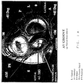
- Figure 1A is a cross-section from above the heart of a portion of the left side of the heart showing the mitral valve, aortic valve, tricuspid valve and pulmonary valve defining the position of those features of the heart relative to the aortic valve.
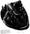
- Figure 1B is a cross-section of a portion of the left side of the heart showing one of the embodiments of guiding introducer for supporting a catheter to ablate a left lateral accessory pathway.
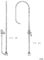
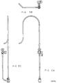
- Figure 2A is a side view of the first embodiment of the guiding introducer for use in the left ventricle around the mitral valve such that the side port tubing attached to the proximal end of the guiding introducer is located directly behind the first section of the guiding introducer.
- Figure 2B is a side view of the first embodiment of the guiding introducer rotated 90 degrees clockwise from the position of Figure 2A, when viewed from the perspective of the proximal end of the guiding introducer, such that the side port tubing is directed to the left of the guiding introducer.
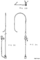
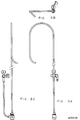
- Figure 3A is a side view of the second embodiment of the guiding introducer for use in the left ventricle, such that the side port tubing attached to the proximal end of the guiding introducer is located directly behind the first section of the guiding introducer.
- Figure 3B is a top view of the second embodiment of the guiding introducer rotated 90 degrees upward about the curved section from the position of Figure 3A, such that the side port tubing is directed upward from the guiding introducer.
- Figure 3C is a side view of the second embodiment of the guiding introducer rotated 90 degrees clockwise from the position of Figure 3A, when viewed from the perspective of the proximal end of the guiding introducer, such that the side port tubing is directed to the left of the guiding introducer.
- Figure 4A is a side view of the third embodiment of the guiding introducer for use in the left ventricle, such that the side port tubing attached to the proximal end of the guiding introducer is located directly behind the first section of the guiding introducer.
- Figure 4B is a top view of the third embodiment of the guiding introducer rotated 90 degrees upward about the curved second section from the position of Figure 4A, such that the side port tubing is directed upward from the guiding introducer.
- Figure 4C is a side view of the third embodiment of the guiding introducer rotated 90 degrees clockwise from the position of Figure 4A, when viewed from the perspective of the proximal end of the guiding introducer, such that the side port tubing is directed to the left of the guiding introducer.
- Figure 5A is a side view of the fourth embodiment of the guiding introducer for use in the left ventricle, such that the side port tubing attached to the proximal end of the guiding introducer is located directly behind the first section of the guiding introducer.
- Figure 5B is a top view of the fourth embodiment of the guiding introducer rotated 90 degrees upward about the curved second section from the position of Figure 5A, such that the side port tubing is directed upward from the guiding introducer.
- Figure 5C is a side view of the fourth embodiment of the guiding introducer rotated 90 degrees clockwise from the position of Figure 5A, when viewed from the perspective of the proximal end of the guiding introducer, such that the side port tubing is directed to the left of the guiding introducer.
- Figure 6A is a side view of the fifth embodiment of the guiding introducer for use in the left ventricle, such that the side port tubing attached to the proximal end of the guiding introducer is located directly behind the first section of the guiding introducer.
- Figure 6B is a top view of the fifth embodiment of the guiding introducer rotated 90 degrees upward about the curved second section from the position of Figure 6A, such that the side port tubing is directed upward from the guiding introducer.
- Figure 6C is a side view of the fifth embodiment of the guiding introducer rotated 90 degrees clockwise from the position of Figure 6A, when viewed from the perspective of the proximal end of the guiding introducer, such that the side port tubing is directed to the left of the guiding introducer.
- a typical human heart includes a right ventricle, a right atrium, left ventricle and left atrium.
- the right atrium is in fluid communication with the superior vena cava and the inferior vena cava.
- the atrioventricular septum separates the atria from the ventricles.
- the tricuspid valve contained within the atrioventricular septum communicates the right atrium with the right ventricle.
- the mitral valve contained within the atrioventricular septum communicates the left atrium with the left ventricle. See Figure 1A.
- the coronary sinus is the large epicardial vein which accommodates most of the venous blood which drains from the myocardium into the right atrium.
- the His-Purkinje system In the normal heart, contraction and relaxation of the heart muscle (myocardium) takes place in an organized fashion as electrochemical signals pass sequentially through the myocardium from the atrial to the ventricular tissue along a well defined route which includes the His-Purkinje system.
- Initial electric impulses are generated at the sinuatrial (SA) node and conducted to the atrioventricular (AV) node.
- the AV node lies near the ostium of the coronary sinus in the interatrial septum in the right atrium.
- the His-Purkinje system begins at the AV node and follows along the membranous interatrial septum toward the tricuspid valve through the atrioventricular septum and into the membranous interventricular septum. At about the middle of the interventricular septum, the His-Purkinje system splits into right and left branches which straddle the summit of the muscular part of the interventricular septum.
- arrhythmia abnormal rhythms occur in the heart which are referred to as arrhythmia.
- W-P-W Wolff-Parkinson-White syndrome
- the cause of this arrhythmia is the existence of an anomalous conduction pathway or pathways that connect the atria muscle tissue directly to the ventricular muscle tissue, thus by-passing the normal His-Purkinje system.
- These pathways are usually located in the fibrous tissue that connect the atrium and the ventricle.
- a technique has been developed to destroy these anomalous conduction pathways by delivering energy into the tissue in which the pathways exist.
- a special catheter with ablation electrodes is positioned as close as possible to the anomalous conduction pathway to maintain constant tissue contact while energy is delivered to destroy the pathway. This same type of contact with the cardiac tissue is also necessary when mapping or other procedures are employed relating to these pathways.
- anomalous conduction pathways can be located either in the right atrium or in the left atrium with the other end of the pathway located in the corresponding ventricle.
- the anomalous conduction pathway is located between the left atrium and the left ventricle.
- One is to introduce the catheter into the femoral artery by a standard introducer sheath and advance it up the aorta, across the aortic valve into the left ventricle and then position its tip under the mitral valve annulus near the anomalous conduction pathway. See Figures 1A and 1B. This is commonly referred to as the "retrograde" approach.
- transseptal approach is to introduce a transseptal sheath apparatus, a long single plane curve introducer, into the right femoral vein and advance it through the inferior vena cava into the right atrium.
- a puncture is then made through the fossa ovalis in the interatrial septum and the apparatus is advanced into the left atrium where the trocar and dilator of the apparatus are removed, leaving the sheath in position in the left atrium.
- the mapping or ablation catheter is then inserted through the sheath and into the left atrium and positioned on top of the mitral valve annulus near the anomalous conduction pathway.
- Specific positions may be chosen for the mapping or ablation on the left side of the heart, including specifically postero lateral, lateral, antero lateral, posterior, postero septal, septal, antero medial and anterior positions around the mitral valve annulus. See Figure 1A.
- the guiding introducer of the present invention for use in the left ventricle is comprised of a first, second and third section.
- Each section is preferably formed as an integral portion of the entire guiding introducer without discrete sections.
- the division of the guiding introducer into three different sections better defines the shape of the guiding introducer.
- Each of the guiding introducers will be shown in either two or three views. In each of the views for ease of analysis, the guiding introducer and each of its sections will be secured to a valve for attachment to a conventional side port tubing and stop cock.
- the shape of the guiding introducer will be described, making reference to its position in relation to the side port and side port tubing where the proximal end of the guiding introducer is secured to the side port tubing.
- the side port tubing is generally viewed as if it is behind the first section of the guiding introducer.
- the remaining figures of each embodiment will show the guiding catheter after rotation of the guiding introducer about the axis of one of the sections. Each figure will focus upon the curved portion of the third section and the extent it is curved away from the plane formed by the first two sections when viewed from above the guiding introducer. See Figures 2B, 3B, 4B, 5B, and 6B.)
- the first and second sections in each embodiment of the guiding introducers are generally the same shape.
- the first section is a conventional, generally elongated hollow, straight catheter section of sufficient length for introduction into the patient and for manipulation from the point of insertion to the specific desired location within the heart. (The overall length of the first section as shown in the drawing has been reduced for ease of viewing.)
- the second section Merged with the distal end of the first section of the guiding introducer is the second section which is curved in a smooth, generally flat curve, curving to the left as shown in Figures 2A, 3A, 4A, 5A and 6A.
- This curve has a radius of from about 1.0 in. to about 2.0 in. and preferably from about 1.3 in. to about 1.7 in.
- the extent of the arc of the curve is from about 160 to about 200 degrees and preferably from about 170 to about 190 degrees of arc.
- the third section of the guiding introducer is merged with the distal end of the second section.
- the structure of the third section of the guiding introducer will depend on the location adjacent to the mitral valve being treated.
- the guiding introducers of the instant invention are used to place a mapping or ablating catheter in a position in relation to the mitral valve which is postero lateral, lateral, anterio lateral, posterior, postero septal, septal, anterio medial or anterior to the mitral valve annulus on the ventricular side of the heart. See Figure 1A.
- the third section is generally comprised of a straight portion merged with a curved portion.
- the straight portion is from about 2.0 in. to about 3.5 in. in length and preferably from about 2.3 to about 3.0 in. in length. This straight portion is preferably in the same plane as are the first and second sections (within about 20 degrees of coplanar).
- this curved portion curves to the right (as shown in Figure 2A) with a radius of about 0.5 to about 1.5 in. and preferably about 0.8 to about 1.2 in.
- This curved portion curves in an arc from about 70 to about 110 degrees and preferably from about 80 to about 100 degrees of arc.
- This curved portion is about 0.6 to about 1.5 in. away from the straight section and preferably about 0.8 to about 1.2 in. from the straight section ending in a distal tip.
- this curved portion may also be curved out of the plane formed by the first and second sections from about 30 degrees clockwise to about 30 degrees counterclockwise when viewed from the top of the arc of the curve of the second section.
- This first embodiment is designed for use in the ablation and mapping of accessory pathways located lateral to the mitral valve annulus on the ventricular side. See Figure 1B.
- the distal tip of all of the guiding introducers may be, and preferably will be, tapered to form a good transition with a dilator. This tapering is preferably less than 10° and more preferably about 4° to about 7°.
- the guiding introducers preferably may also contain one or a multitude of radiopaque tip marker bands near the distal tip of the guiding introducer.
- These guiding introducers also preferably contain one or a plurality of vents near the distal tip of the guiding introducer, preferably three or four such vents. The vents are preferably located no more than about 1.00 in. from the tip of the guiding introducer and more preferably 0.10 to about 1.00 in. from the tip.
- vents should be in the range of about 40 to about 60/1000 of an inch in diameter.
- vents are generally designed to prevent air embolisms from entering the guiding introducer caused by the withdrawal of the catheter contained within the guiding introducer in the event the distal end of the guiding introducer is occluded. For example, if the tip of the guiding introducer is placed against the myocardium and the catheter located within the guiding introducer is withdrawn, a vacuum may be created within the catheter if no vents are provided. If such vacuum is formed, air may be forced back into the guiding introducer by the reintroduction of a catheter into the lumen of the guiding introducer.
- vents near the distal tip of the guiding introducer prevents the formation of such vacuum by permitting fluid, presumably blood, to be drawn into the lumen of the guiding introducer as the catheter is being removed from the guiding introducer, thus preventing the formation of air embolisms within the guiding introducer.
- the guiding introducers may be made of any material suitable for use in humans which has a memory or permits distortion from, and substantial return to, the desired three dimensional or complex multiplanar shape.
- the internal diameter of the guiding introducer may vary from about 6 to about 10 "French” (1 French equals 1/3 of a millimeter).
- Such guiding introducer can accept dilators from about 6 to about 10 French and appropriate guidewires.
- modifications in size or shape can be made to the instant guiding introducers.
- Variations in size and shape of the guiding introducers are also intended to encompass pediatric uses, although the preferred uses are for adult human hearts. It is well recognized that pediatric uses may require reductions in size of the various sections of the guiding introducer, in particular the first section, but without any significant modification to the shape or curves of the guiding introducer.
- variations in size or shape of the guiding introducers are also intended to encompass the specialized situations that sometimes occur in patients with enlarged and rotated hearts.
- the second embodiment of the guiding introducer ( Figures 3A, 3B and 3C) is designed for use in the ablation and mapping of accessory pathways located posterior to the mitral valve annulus on the ventricular side. See Figure 1A.
- the first and second sections along with the straight portion of the third section are the same as was previously disclosed in the description of the first embodiment.
- the difference in shape lies in the curved portion of the third section. Specifically, the shape and location of the curved portion varies depending upon which accessory pathway is to be mapped and/or ablated.
- this curved portion curves not only toward the first section, as with the first embodiment, but also curves out of the plane of the first and second sections approximately 30 to about 60 degrees and preferably from about 40 to about 50 degrees counterclockwise when viewed from the top of the arc of the curve of the second section. (See Figure 3B).
- the curved portion is a compound curve, curving first out of plane, as shown in Figure 3B, and at the same time curving to the right as shown in Figure 3A.
- the curve to the right of the curved portion has a radius of from about 0.7 to about 1.3 in. and preferably from about 0.9 to about 1.1 in.
- the arc of this curved portion is preferably from about 70 to about 110 degrees and more preferably from about 80 to about 100 degrees ending in the distal tip. See Figure 3C.
- the distance from the straight portion of the third section to the distal tip of the guiding catheter is preferably from about 0.8 to about 1.2 in. and more preferably from about 0.9 to about 1.1 in. ending in the distal tip.
- the third embodiment of the guiding introducer ( Figures 4A, 4B and 4C) is designed for use in the ablation and mapping of accessory pathways located postero septal to the mitral valve annulus on the ventricular side. See Figure 1A.
- the shape of this guiding catheter is similar to the second embodiment except the curved portion of the third section is rotated out of plane to a greater extent than is shown in the second embodiment.
- the first section, second section and straight portion of the third section of this third embodiment are generally the same as disclosed in the first and second embodiments.
- the curved portion of the third section is again comprised of a compound curve, similar to the compound curve of the second embodiment except it is curved out of plane to a greater extent, from about 60 to about 115 degrees, and preferably from about 80 to about 100 degrees counterclockwise when viewed from the top of the arc of the curve of the second section.
- the arc of this curved portion is preferably from about 70 to about 110 degrees and more preferably from about 80 to about 100 degrees.
- the curve has a radius of from about 0.7 to about 1.3 in. and preferably from about 0.9 to about 1.1 in. See Figures 4B and 4C.
- the shape and length of the curved portion is otherwise the same as was disclosed in the second embodiment.
- the fourth embodiment of the guiding introducer ( Figures 5A, 5B and 5C) is designed for use in the ablation and mapping of accessory pathways located septal to the mitral valve annulus on the ventricular side. See Figure 1A.
- the curved portion of the third section of the fourth embodiment is comprised of a compound curve, curving first out of plane and then curving to the left as shown on Figures 5A and 5B.
- the distinction between the third and fourth embodiment is the extent of the curve out of plane of this curved portion of the third section.
- This curved portion of the third section is out of plane of the first and second sections from about 115 to about 200 degrees and preferably from about 125 to about 160 degrees counterclockwise when viewed from the top of the arc of the curve of the second section. See Figure 5B.
- the arc of this curved portion is preferably from about 70 to about 110 degrees and more preferably from about 80 to about 100 degrees.
- the curve has a radius of from about 0.7 to about 1.3 in. and preferably from about 0.9 to about 1.1 in.
- the second curve of this third section curves to the left in a manner similar to that shown in the first three embodiments with the same overall length. See Figure 5C.
- the fifth embodiment of the guiding introducer ( Figures 6A, 6B and 6C) is designed for use in the ablation and mapping of accessory pathways located anterior to the mitral valve annulus on the ventricular side. See Figure 1A.
- the first, second and the straight portion of the third section are similar to those portions in the first four embodiments.
- the only distinction is in the curved portion of the third section wherein this curved portion is a compound curve, curving out of plane from the first and section sections from about 200 to about 330 degrees and preferably from about 300 to about 330 degrees counterclockwise when viewed from the top of the arc of the curve of the second section. See Figure 6B.
- the arc of this curved portion is preferably from about 70 to about 110 degrees and more preferably from about 80 to about 100 degrees ending in the distal tip.
- the curve has a radius of from about 0.7 to about 1.3 in. and preferably from about 0.9 to about 1.1 in.
- the second curve of this compound curve is similar to that in the first four embodiments in overall length. See Figure 6C.
- a modified Seldinger technique is normally used for the insertion of the catheter into the femoral artery.
- a small skin incision is made at the appropriate location to facilitate the catheter or dilator passage.
- the subcutaneous tissue is then dissected, followed by a puncture of the vessel with an appropriate needle with stylet positioned at a relatively shallow angle.
- the needle is then partially withdrawn and reinserted at a slightly different angle into the vessel, making sure that the needle remains within the vessel.
- a soft flexible tip of an appropriately sized guidewire is then inserted through and a short distance beyond the needle into the vessel. Firmly holding the guidewire in place, the needle is removed.
- the guidewire is then advanced through the artery up to the aorta, across the aortic valve into the left ventricle.
- a dilator is then placed over the guidewire with the guiding introducer placed over the dilator.
- the dilator and guiding introducer generally form an assembly to be advanced together along the guidewire into the left ventricle. After insertion of the assembly, the guidewire and dilator are then withdrawn.
- the catheter to be used for analysis and/or treatment of the anomalous conduction pathways is advanced through the lumen of the guiding introducer and is placed at an appropriate location near the mitral valve annulus. The choice of the guiding introducer to be used will depend on the location of the anomalous conduction pathway, as has previously been discussed.
- the distal portion of the guiding introducer can be manipulated to direct the ablation electrode of an ablation and/or mapping catheter placed within the lumen of the guiding introducer, to a specific internal surface with the left ventricle.
- the distal end of the guiding introducer can be maintained in that fixed location or surface position of the endocardial structure to permit the appropriate procedures to be performed. If sensing procedures are involved, the guiding introducer is placed in the desired location.
- an ablation catheter may be placed at a precise location for destruction by the use of energy, for example, thermal, laser, direct current (low energy DC, high energy DC or fulgutronization procedures) radiofrequency energy (possibly along with reduced temperature or iced saline or solution procedures).
- energy for example, thermal, laser, direct current (low energy DC, high energy DC or fulgutronization procedures) radiofrequency energy (possibly along with reduced temperature or iced saline or solution procedures).
- This precise location of the ablation catheter electrode is important as there will be no dilution of the energy delivered due to unfocused energy being dissipated over the cardiac chamber and lost in the circulating blood by a constantly moving electrode of the ablating catheter. This permits a significantly reduced amount of energy to be applied while still achieving efficient ablation. Further, time used to perform the procedure is significantly reduced over procedures where no guiding introducer is used.
Abstract
A process for the mapping and/or ablation of accessory pathways around the mitral valve using a retrograde approach by use of ablation and/or mapping catheters guided by precurved guiding introducers. Also disclosed are shapes for the guiding introducers to be used for the ablation and/or mapping of the accessory pathways around the mitral valve using a retrograde approach.
Description
- This invention relates to introducers. More particularly, this invention relates to guiding introducers of specific shapes for use within the left ventricle of the human heart for the treatment of accessory pathways around the mitral valve.
- Introducers and catheters have been in use for medical procedures for many years. For example, one use has been to convey an electrical stimulus to a selected location within the human body. Another use is to monitor and make measurements for diagnostic tests within the human body. Catheters may be used by a physician to examine, diagnose and treat while positioned at a specific location within the body which is otherwise inaccessible without more invasive procedures. In use, catheters may be inserted into a major vein or artery which is near the body surface. These catheters are then guided to the specific location for examination, diagnosis or treatment by manipulating the catheter through the artery or vein of the human body.
- Catheters have become increasingly useful in remote and difficult to reach locations within the body. However, the utilization of these catheters is frequently limited because of the need for the precise placement of the tip of the catheter at a specific location within the body.
- Control of the movement of catheters to achieve such precise placement is difficult because of the inherent structure of a catheter. The body of a conventional catheter is long and tubular. To provide sufficient control of the movement of the catheter, it is necessary that its structure be somewhat rigid. However, the catheter must not be so rigid as to prevent the bending or curving necessary for movement through the vein, artery or other body part to arrive at the specified location. Further, the catheter must not be so rigid as to cause damage to the artery or vein while it is being moved within the body.
- While it is important that the catheter not be so rigid as to cause injury, it is also important that there be sufficient rigidity in the catheter to accommodate torque control, i.e., the ability to transmit a twisting force along the length of the catheter. Sufficient torque control enables controlled maneuverability of the catheter by the application of a twisting force at the proximal end of the catheter that is transmitted along the catheter to its distal end. The need for greater torque control often conflicts with the need for reduced rigidity to prevent injury to the body vessel.
- Catheters are used increasingly for medical procedures involving the human heart. In these procedures a catheter is typically advanced to the heart through veins or arteries and then is positioned at a specified location within the heart. Typically, the catheter is inserted in an artery or vein in the leg, neck, upper chest or arm of the patient and threaded, often with the aid of a guidewire or introducer, through various arteries or veins until the tip of the catheter reaches the desired location in the heart.
- The distal end of a catheter used in such a procedure is sometimes preformed into a desired curvature so that by torquing the catheter about its longitudinal axis, the catheter can be manipulated to the desired location within the heart or in the arteries or veins associated with the heart. For example, U.S. Patent No. 4,882,777 discloses a catheter with a complex curvature at its distal end for use in a specific procedure in the right ventricle of a human heart. U.S. Patent No. 5,231,994 discloses a guide catheter for guiding a balloon catheter for the dilation of coronary arteries. U.S. Patent No. 4,117,836 discloses a catheter for the selective coronary angiography of the left coronary artery and U.S. Patent Nos. 5,215,540, 5,016,640 and 4,883,058 disclose catheters for selective coronary angiography of the right coronary artery. U.S. patent No. 5,242,441 discloses a deflectable catheter for ablation procedures in the ventricular chamber. See also U.S. Patent No. 4,033,031. In addition, U.S. Patent No. 4,898,591 discloses a catheter with inner and outer layers containing braided portions. The '591 patent also discloses a number of different curvatures for intravascular catheters. Thus, there are a number of references which disclose catheters with predetermined shapes, designed for use during specific medical procedures generally associated with the heart or the vascular system. Because of precise physiology of the heart and the vascular system, catheters or introducers with precisely designed shapes for predetermined uses within the human heart and vascular system are increasingly important.
- Catheter ablation of accessory pathways using a long vascular sheath by means of a transseptal or retrograde approach is discussed in Saul, J.P., et al. "Catheter Ablation of Accessory Atrioventricular Pathways in Young Patients: Use of long vascular sheaths, the transseptal approach and a retrograde left posterior parallel approach" J. Amer. Coll. Card., Vol. 21, no. 3, pps 571-583 (March 1, 1993). See also Swartz, J.F. "Radiofrequency Endocardial Catheter Ablation of Accessory Atrioventricular Pathway Atrial Insertion Sites" Circulation, Vol. 87, no. 2, pps. 487-499 (February, 1993).
- U.S. Patent No. 4,641,649 discloses the use of high frequency energy for the treatment of tachycardia or cardiac dysrhythmia. See also U.S. Patent No. 4,945,912 for the use of radio frequency energy for ablation of cardiac tissue. In addition, various articles have disclosed the ablation of specific locations within the heart by use of energy, in particular, radio frequency energy. See, for example, Gallagher, J.J. et al. "Catheter Technique for Closed-Chest Ablation of the Atrioventricular Conduction System" N. Engl. J. Med. Vol. 306, pp. 194-200 (1982); Horowitz, L.N. "Current Management of Arrhythmia" pp. 373-378 (1991); Falk, R.H. et al. "Atrial Fibrillation Mechanics and Management" pp. 359-374 (1992); and Singer, I. "Clinical Manual of Electrophysiology" pp. 421-431 (1993).
- In addition, the use of radio frequency ablation energy for the treatment of Wolff-Parkinson-White Syndrome in the left atrium by use of a transseptal sheath is disclosed in Swartz, J.F. et al. "Radiofrequency Endocardial Catheter Ablation of Accessory Atrioventricular Pathway Atrial Insertion Sites" Circulation Vol. 87, pp. 487-499 (1993). See also Tracey, C.N. "Radio Frequency Catheter Ablation of Ectopic Atrial Tachycardia Using Paced Activation Sequence Mapping" J. Am. Coll. Cardiol. Vol. 21, pp. 910-917 (1993). See also U.S. Patent Nos. 5,172,699, 5,222,501 and 5,242,441.
- Accordingly, it is an object of this invention to prepare a guiding introducer for selected medical procedures in the left ventricle.
- It is a further object of this invention to prepare a guiding introducer for use in selected electrophysiology procedures within the left ventricle of the heart.
- Another object of this invention is to prepare a guiding introducer for use in selected ablation procedures within the left ventricle of the heart.
- These and other objects are obtained by the design of the guiding introducers disclosed in the instant invention.
- The instant invention includes a process for the ablation and mapping of accessory pathways around the mitral valve of the left ventricle of the heart using a retrograde approach comprising
- (a) introducing into the left ventricle a precurved, guiding introducer, wherein said guiding introducer contains a lumen running lengthwise therethrough, a proximal and a distal end and wherein the introducer is comprised of shaped first, second and third sections;
- (b) introducing into the lumen of the guiding introducer an ablation and/or mapping catheter containing a proximal and distal end, wherein said catheter has one or more electrodes located at or near the distal end of the catheter;
- (c) guiding the catheter to a selected location about the mitral valve of the heart on the ventricular side by use of the guiding introducer; and
- (d) mapping and/or ablating the selected location about the mitral valve by use of the electrodes of the catheter.
- In addition, the instant invention is a guiding introducer to be used in the left ventricle comprised of a first, second and third sections wherein the first section is a generally elongated straight section which is merged at its distal end with the second and a third section which forms a complex curved section.
- Figure 1A is a cross-section from above the heart of a portion of the left side of the heart showing the mitral valve, aortic valve, tricuspid valve and pulmonary valve defining the position of those features of the heart relative to the aortic valve.
- Figure 1B is a cross-section of a portion of the left side of the heart showing one of the embodiments of guiding introducer for supporting a catheter to ablate a left lateral accessory pathway.
- Figure 2A is a side view of the first embodiment of the guiding introducer for use in the left ventricle around the mitral valve such that the side port tubing attached to the proximal end of the guiding introducer is located directly behind the first section of the guiding introducer.
- Figure 2B is a side view of the first embodiment of the guiding introducer rotated 90 degrees clockwise from the position of Figure 2A, when viewed from the perspective of the proximal end of the guiding introducer, such that the side port tubing is directed to the left of the guiding introducer.
- Figure 3A is a side view of the second embodiment of the guiding introducer for use in the left ventricle, such that the side port tubing attached to the proximal end of the guiding introducer is located directly behind the first section of the guiding introducer.
- Figure 3B is a top view of the second embodiment of the guiding introducer rotated 90 degrees upward about the curved section from the position of Figure 3A, such that the side port tubing is directed upward from the guiding introducer.
- Figure 3C is a side view of the second embodiment of the guiding introducer rotated 90 degrees clockwise from the position of Figure 3A, when viewed from the perspective of the proximal end of the guiding introducer, such that the side port tubing is directed to the left of the guiding introducer.
- Figure 4A is a side view of the third embodiment of the guiding introducer for use in the left ventricle, such that the side port tubing attached to the proximal end of the guiding introducer is located directly behind the first section of the guiding introducer.
- Figure 4B is a top view of the third embodiment of the guiding introducer rotated 90 degrees upward about the curved second section from the position of Figure 4A, such that the side port tubing is directed upward from the guiding introducer.
- Figure 4C is a side view of the third embodiment of the guiding introducer rotated 90 degrees clockwise from the position of Figure 4A, when viewed from the perspective of the proximal end of the guiding introducer, such that the side port tubing is directed to the left of the guiding introducer.
- Figure 5A is a side view of the fourth embodiment of the guiding introducer for use in the left ventricle, such that the side port tubing attached to the proximal end of the guiding introducer is located directly behind the first section of the guiding introducer.
- Figure 5B is a top view of the fourth embodiment of the guiding introducer rotated 90 degrees upward about the curved second section from the position of Figure 5A, such that the side port tubing is directed upward from the guiding introducer.
- Figure 5C is a side view of the fourth embodiment of the guiding introducer rotated 90 degrees clockwise from the position of Figure 5A, when viewed from the perspective of the proximal end of the guiding introducer, such that the side port tubing is directed to the left of the guiding introducer.
- Figure 6A is a side view of the fifth embodiment of the guiding introducer for use in the left ventricle, such that the side port tubing attached to the proximal end of the guiding introducer is located directly behind the first section of the guiding introducer.
- Figure 6B is a top view of the fifth embodiment of the guiding introducer rotated 90 degrees upward about the curved second section from the position of Figure 6A, such that the side port tubing is directed upward from the guiding introducer.
- Figure 6C is a side view of the fifth embodiment of the guiding introducer rotated 90 degrees clockwise from the position of Figure 6A, when viewed from the perspective of the proximal end of the guiding introducer, such that the side port tubing is directed to the left of the guiding introducer.
- A typical human heart includes a right ventricle, a right atrium, left ventricle and left atrium. The right atrium is in fluid communication with the superior vena cava and the inferior vena cava. The atrioventricular septum separates the atria from the ventricles. The tricuspid valve contained within the atrioventricular septum communicates the right atrium with the right ventricle. The mitral valve contained within the atrioventricular septum communicates the left atrium with the left ventricle. See Figure 1A. On the inner wall of the right atrium, where it is connected with the left atrium, is a recessed portion, the fossa ovalis. Between the fossa ovalis and the tricuspid valve is the opening or ostium for the coronary sinus. The coronary sinus is the large epicardial vein which accommodates most of the venous blood which drains from the myocardium into the right atrium.
- In the normal heart, contraction and relaxation of the heart muscle (myocardium) takes place in an organized fashion as electrochemical signals pass sequentially through the myocardium from the atrial to the ventricular tissue along a well defined route which includes the His-Purkinje system. Initial electric impulses are generated at the sinuatrial (SA) node and conducted to the atrioventricular (AV) node. The AV node lies near the ostium of the coronary sinus in the interatrial septum in the right atrium. The His-Purkinje system begins at the AV node and follows along the membranous interatrial septum toward the tricuspid valve through the atrioventricular septum and into the membranous interventricular septum. At about the middle of the interventricular septum, the His-Purkinje system splits into right and left branches which straddle the summit of the muscular part of the interventricular septum.
- Sometimes abnormal rhythms occur in the heart which are referred to as arrhythmia. For example, patients diagnosed with Wolff-Parkinson-White syndrome (W-P-W) have an arrhythmia. The cause of this arrhythmia is the existence of an anomalous conduction pathway or pathways that connect the atria muscle tissue directly to the ventricular muscle tissue, thus by-passing the normal His-Purkinje system. These pathways are usually located in the fibrous tissue that connect the atrium and the ventricle. In recent years a technique has been developed to destroy these anomalous conduction pathways by delivering energy into the tissue in which the pathways exist. To accomplish this procedure a special catheter with ablation electrodes is positioned as close as possible to the anomalous conduction pathway to maintain constant tissue contact while energy is delivered to destroy the pathway. This same type of contact with the cardiac tissue is also necessary when mapping or other procedures are employed relating to these pathways.
- One end of these anomalous conduction pathways can be located either in the right atrium or in the left atrium with the other end of the pathway located in the corresponding ventricle. When the anomalous conduction pathway is located between the left atrium and the left ventricle, there are two approaches to positioning the catheter near that pathway for the appropriate medical procedure. One is to introduce the catheter into the femoral artery by a standard introducer sheath and advance it up the aorta, across the aortic valve into the left ventricle and then position its tip under the mitral valve annulus near the anomalous conduction pathway. See Figures 1A and 1B. This is commonly referred to as the "retrograde" approach.
- The other approach, commonly referred to as the transseptal approach, is to introduce a transseptal sheath apparatus, a long single plane curve introducer, into the right femoral vein and advance it through the inferior vena cava into the right atrium. A puncture is then made through the fossa ovalis in the interatrial septum and the apparatus is advanced into the left atrium where the trocar and dilator of the apparatus are removed, leaving the sheath in position in the left atrium. The mapping or ablation catheter is then inserted through the sheath and into the left atrium and positioned on top of the mitral valve annulus near the anomalous conduction pathway. Specific positions may be chosen for the mapping or ablation on the left side of the heart, including specifically postero lateral, lateral, antero lateral, posterior, postero septal, septal, antero medial and anterior positions around the mitral valve annulus. See Figure 1A.
- Mere introduction of the ablation and mapping catheter into the left ventricle for a retrograde approach is not sufficient to effectively and efficiently perform these medical procedures, especially for the mapping or ablation of anomalous conduction pathways. The medical practitioner commonly monitors the introduction of the catheter and its progress through the vascular system by a fluoroscope. Such fluoroscopes cannot easily identify the specific features of the heart in general, and the critically important structures of the left ventricle in specific, thus making placement of the ablation electrode of the ablation catheter difficult. This placement is especially difficult as the beating heart is in motion. In addition, the ablation catheter will be moving within the left ventricle as blood is being pumped through the heart throughout the procedure. The guiding introducers of the instant invention address and solve these problems.
- Referring now to Figures 2 through 6, the guiding introducer of the present invention for use in the left ventricle is comprised of a first, second and third section. (Each section is preferably formed as an integral portion of the entire guiding introducer without discrete sections. However, the division of the guiding introducer into three different sections better defines the shape of the guiding introducer. Each of the guiding introducers will be shown in either two or three views. In each of the views for ease of analysis, the guiding introducer and each of its sections will be secured to a valve for attachment to a conventional side port tubing and stop cock. In each such arrangement, the shape of the guiding introducer will be described, making reference to its position in relation to the side port and side port tubing where the proximal end of the guiding introducer is secured to the side port tubing. In the first referenced figure of each embodiment (Figures 2A, 3A, 4A, 5A and 6A), the side port tubing is generally viewed as if it is behind the first section of the guiding introducer. The remaining figures of each embodiment will show the guiding catheter after rotation of the guiding introducer about the axis of one of the sections. Each figure will focus upon the curved portion of the third section and the extent it is curved away from the plane formed by the first two sections when viewed from above the guiding introducer. See Figures 2B, 3B, 4B, 5B, and 6B.)
- The first and second sections in each embodiment of the guiding introducers are generally the same shape. The first section is a conventional, generally elongated hollow, straight catheter section of sufficient length for introduction into the patient and for manipulation from the point of insertion to the specific desired location within the heart. (The overall length of the first section as shown in the drawing has been reduced for ease of viewing.)
- Merged with the distal end of the first section of the guiding introducer is the second section which is curved in a smooth, generally flat curve, curving to the left as shown in Figures 2A, 3A, 4A, 5A and 6A. This curve has a radius of from about 1.0 in. to about 2.0 in. and preferably from about 1.3 in. to about 1.7 in. The extent of the arc of the curve is from about 160 to about 200 degrees and preferably from about 170 to about 190 degrees of arc.
- The third section of the guiding introducer is merged with the distal end of the second section. The structure of the third section of the guiding introducer will depend on the location adjacent to the mitral valve being treated. As previously stated, the guiding introducers of the instant invention are used to place a mapping or ablating catheter in a position in relation to the mitral valve which is postero lateral, lateral, anterio lateral, posterior, postero septal, septal, anterio medial or anterior to the mitral valve annulus on the ventricular side of the heart. See Figure 1A. To accomplish these procedures, the third section is generally comprised of a straight portion merged with a curved portion. The straight portion is from about 2.0 in. to about 3.5 in. in length and preferably from about 2.3 to about 3.0 in. in length. This straight portion is preferably in the same plane as are the first and second sections (within about 20 degrees of coplanar).
- In the first embodiment (Figures 2A and 2B) this curved portion curves to the right (as shown in Figure 2A) with a radius of about 0.5 to about 1.5 in. and preferably about 0.8 to about 1.2 in. This curved portion curves in an arc from about 70 to about 110 degrees and preferably from about 80 to about 100 degrees of arc. This curved portion is about 0.6 to about 1.5 in. away from the straight section and preferably about 0.8 to about 1.2 in. from the straight section ending in a distal tip. In addition to the curve toward the first section, this curved portion may also be curved out of the plane formed by the first and second sections from about 30 degrees clockwise to about 30 degrees counterclockwise when viewed from the top of the arc of the curve of the second section. This first embodiment is designed for use in the ablation and mapping of accessory pathways located lateral to the mitral valve annulus on the ventricular side. See Figure 1B.
- The distal tip of all of the guiding introducers may be, and preferably will be, tapered to form a good transition with a dilator. This tapering is preferably less than 10° and more preferably about 4° to about 7°. The guiding introducers preferably may also contain one or a multitude of radiopaque tip marker bands near the distal tip of the guiding introducer. These guiding introducers also preferably contain one or a plurality of vents near the distal tip of the guiding introducer, preferably three or four such vents. The vents are preferably located no more than about 1.00 in. from the tip of the guiding introducer and more preferably 0.10 to about 1.00 in. from the tip. The size of these vents should be in the range of about 40 to about 60/1000 of an inch in diameter. These vents are generally designed to prevent air embolisms from entering the guiding introducer caused by the withdrawal of the catheter contained within the guiding introducer in the event the distal end of the guiding introducer is occluded. For example, if the tip of the guiding introducer is placed against the myocardium and the catheter located within the guiding introducer is withdrawn, a vacuum may be created within the catheter if no vents are provided. If such vacuum is formed, air may be forced back into the guiding introducer by the reintroduction of a catheter into the lumen of the guiding introducer. Such air embolisms could cause significant problems in the patient, including the possibility of a stroke, heart attack or other such problems common with air embolisms in the heart. The addition of vents near the distal tip of the guiding introducer prevents the formation of such vacuum by permitting fluid, presumably blood, to be drawn into the lumen of the guiding introducer as the catheter is being removed from the guiding introducer, thus preventing the formation of air embolisms within the guiding introducer.
- The guiding introducers may be made of any material suitable for use in humans which has a memory or permits distortion from, and substantial return to, the desired three dimensional or complex multiplanar shape. For the purpose of illustration and not limitation, the internal diameter of the guiding introducer may vary from about 6 to about 10 "French" (1 French equals 1/3 of a millimeter). Such guiding introducer can accept dilators from about 6 to about 10 French and appropriate guidewires. Obviously, if larger or smaller dilators or catheters are used in conjunction with the guiding introducers of the instant invention, modifications in size or shape can be made to the instant guiding introducers.
- Variations in size and shape of the guiding introducers are also intended to encompass pediatric uses, although the preferred uses are for adult human hearts. It is well recognized that pediatric uses may require reductions in size of the various sections of the guiding introducer, in particular the first section, but without any significant modification to the shape or curves of the guiding introducer.
- In addition, variations in size or shape of the guiding introducers are also intended to encompass the specialized situations that sometimes occur in patients with enlarged and rotated hearts.
- The second embodiment of the guiding introducer (Figures 3A, 3B and 3C) is designed for use in the ablation and mapping of accessory pathways located posterior to the mitral valve annulus on the ventricular side. See Figure 1A. In this embodiment and in the succeeding three embodiments, the first and second sections along with the straight portion of the third section are the same as was previously disclosed in the description of the first embodiment. The difference in shape lies in the curved portion of the third section. Specifically, the shape and location of the curved portion varies depending upon which accessory pathway is to be mapped and/or ablated. In the second embodiment, this curved portion curves not only toward the first section, as with the first embodiment, but also curves out of the plane of the first and second sections approximately 30 to about 60 degrees and preferably from about 40 to about 50 degrees counterclockwise when viewed from the top of the arc of the curve of the second section. (See Figure 3B). To accomplish this out of plane curvature, the curved portion is a compound curve, curving first out of plane, as shown in Figure 3B, and at the same time curving to the right as shown in Figure 3A. The curve to the right of the curved portion has a radius of from about 0.7 to about 1.3 in. and preferably from about 0.9 to about 1.1 in. The arc of this curved portion is preferably from about 70 to about 110 degrees and more preferably from about 80 to about 100 degrees ending in the distal tip. See Figure 3C. The distance from the straight portion of the third section to the distal tip of the guiding catheter is preferably from about 0.8 to about 1.2 in. and more preferably from about 0.9 to about 1.1 in. ending in the distal tip.
- The third embodiment of the guiding introducer (Figures 4A, 4B and 4C) is designed for use in the ablation and mapping of accessory pathways located postero septal to the mitral valve annulus on the ventricular side. See Figure 1A. The shape of this guiding catheter is similar to the second embodiment except the curved portion of the third section is rotated out of plane to a greater extent than is shown in the second embodiment. Thus, the first section, second section and straight portion of the third section of this third embodiment are generally the same as disclosed in the first and second embodiments. As with the second embodiment, the curved portion of the third section is again comprised of a compound curve, similar to the compound curve of the second embodiment except it is curved out of plane to a greater extent, from about 60 to about 115 degrees, and preferably from about 80 to about 100 degrees counterclockwise when viewed from the top of the arc of the curve of the second section. See Figure 4B. The arc of this curved portion is preferably from about 70 to about 110 degrees and more preferably from about 80 to about 100 degrees. The curve has a radius of from about 0.7 to about 1.3 in. and preferably from about 0.9 to about 1.1 in. See Figures 4B and 4C. The shape and length of the curved portion is otherwise the same as was disclosed in the second embodiment. The shape of this curved portion is best shown in Figures 4B and 4C with Figure 4C being the same as Figure 4A except rotated 90 degrees to the right such that the stop cock is directed to the left of the first section of the guiding introducer. Otherwise, the lengths of the curves are the same as was disclosed in the second embodiment.
- The fourth embodiment of the guiding introducer (Figures 5A, 5B and 5C) is designed for use in the ablation and mapping of accessory pathways located septal to the mitral valve annulus on the ventricular side. See Figure 1A. Once again, the first, second and straight portion of the third section are the same as disclosed in the first three embodiments. The curved portion of the third section of the fourth embodiment is comprised of a compound curve, curving first out of plane and then curving to the left as shown on Figures 5A and 5B. The distinction between the third and fourth embodiment is the extent of the curve out of plane of this curved portion of the third section. This curved portion of the third section is out of plane of the first and second sections from about 115 to about 200 degrees and preferably from about 125 to about 160 degrees counterclockwise when viewed from the top of the arc of the curve of the second section. See Figure 5B. The arc of this curved portion is preferably from about 70 to about 110 degrees and more preferably from about 80 to about 100 degrees. The curve has a radius of from about 0.7 to about 1.3 in. and preferably from about 0.9 to about 1.1 in. The second curve of this third section curves to the left in a manner similar to that shown in the first three embodiments with the same overall length. See Figure 5C.
- The fifth embodiment of the guiding introducer (Figures 6A, 6B and 6C) is designed for use in the ablation and mapping of accessory pathways located anterior to the mitral valve annulus on the ventricular side. See Figure 1A. Once again, the first, second and the straight portion of the third section are similar to those portions in the first four embodiments. The only distinction is in the curved portion of the third section wherein this curved portion is a compound curve, curving out of plane from the first and section sections from about 200 to about 330 degrees and preferably from about 300 to about 330 degrees counterclockwise when viewed from the top of the arc of the curve of the second section. See Figure 6B. The arc of this curved portion is preferably from about 70 to about 110 degrees and more preferably from about 80 to about 100 degrees ending in the distal tip. The curve has a radius of from about 0.7 to about 1.3 in. and preferably from about 0.9 to about 1.1 in. The second curve of this compound curve is similar to that in the first four embodiments in overall length. See Figure 6C.
- As a result of these five embodiments, five separate guiding introducers are disclosed which are similar in shape except for the curved portion of the third section. This curved portion is also similar in all five embodiments except to the extent that it is out of plane with the first and second sections.
- In operation, a modified Seldinger technique is normally used for the insertion of the catheter into the femoral artery. Using this procedure, a small skin incision is made at the appropriate location to facilitate the catheter or dilator passage. The subcutaneous tissue is then dissected, followed by a puncture of the vessel with an appropriate needle with stylet positioned at a relatively shallow angle. The needle is then partially withdrawn and reinserted at a slightly different angle into the vessel, making sure that the needle remains within the vessel. A soft flexible tip of an appropriately sized guidewire is then inserted through and a short distance beyond the needle into the vessel. Firmly holding the guidewire in place, the needle is removed. The guidewire is then advanced through the artery up to the aorta, across the aortic valve into the left ventricle. With the guidewire in place, a dilator is then placed over the guidewire with the guiding introducer placed over the dilator. The dilator and guiding introducer generally form an assembly to be advanced together along the guidewire into the left ventricle. After insertion of the assembly, the guidewire and dilator are then withdrawn. The catheter to be used for analysis and/or treatment of the anomalous conduction pathways is advanced through the lumen of the guiding introducer and is placed at an appropriate location near the mitral valve annulus. The choice of the guiding introducer to be used will depend on the location of the anomalous conduction pathway, as has previously been discussed.
- By choice of the desired predetermined shape of the guiding introducer in conjunction with fluoroscopic viewing, the distal portion of the guiding introducer can be manipulated to direct the ablation electrode of an ablation and/or mapping catheter placed within the lumen of the guiding introducer, to a specific internal surface with the left ventricle. In addition, by providing sufficient rigidity and support as the guiding introducer is held in place by the anatomical structure of the heart as well as the vasculature, the distal end of the guiding introducer can be maintained in that fixed location or surface position of the endocardial structure to permit the appropriate procedures to be performed. If sensing procedures are involved, the guiding introducer is placed in the desired location. At that point, the electrical activity of the heart peculiar to that location can be precisely determined by use of a sensing electrophysiology catheter placed within the guiding introducer. Further, as the guiding introducer permits precise location of catheters, an ablation catheter may be placed at a precise location for destruction by the use of energy, for example, thermal, laser, direct current (low energy DC, high energy DC or fulgutronization procedures) radiofrequency energy (possibly along with reduced temperature or iced saline or solution procedures). This precise location of the ablation catheter electrode is important as there will be no dilution of the energy delivered due to unfocused energy being dissipated over the cardiac chamber and lost in the circulating blood by a constantly moving electrode of the ablating catheter. This permits a significantly reduced amount of energy to be applied while still achieving efficient ablation. Further, time used to perform the procedure is significantly reduced over procedures where no guiding introducer is used.
- It will be apparent from the foregoing that while particular forms of the invention have been illustrated and described, various modifications can be made without departing from the spirit and scope of the invention. Accordingly, it is not intended that this invention be limited except as by the appended claims.
Claims (10)
- A guiding introducer for use with an ablation catheter for the ablation and/or mapping of accessory pathways around the mitral valve of the left ventricle of the heart from the ventricle side comprising shaped first, second and third sections.
- The guiding introducer of Claim 1 wherein the first section is a generally elongated hollow straight catheter section of sufficient length for introduction into the patient and for manipulation from the point of insertion through to a desired location within the heart.
- The guiding introducer of Claims 1 or 2 wherein the second section is a curved section comprised of a smooth flat curve with a radius of about 1.0 in. to about 2.0 in., wherein the arc of the curve is from about 160 to about 200 degrees, and wherein preferably the radius of the curved section of the second section is from about 1.3 in. to about 1.7 in., wherein the arc of the curve is from about 170 to about 190 degrees of arc.
- The guiding introducer of any one of Claims 1 to 3 wherein the third section is comprised of a straight portion and a curved portion, and wherein preferably the straight portion is from about 2.0 to about 3.5 in. in length and the curved portion comprises a curve with a radius of about 0.5 to about 1.5 in. with an arc of about 70 to about 110 degrees, wherein the curve is within about 45 degrees of being in a plane formed by the first and second sections, and wherein the curved portion curves generally toward the first section.
- The guiding introducer of any one of Claims 1 to 4 wherein the straight portion is from about 2.0 to about 3.5 in. in length and the curved portion comprises a curve with a radius of about 0.5 to about 1.5 in., with an arc of about 70 to about 110 degrees, wherein the curve is within about 45 to about 60 degrees of a plane formed by the first and second sections.
- The guiding introducer of any one of Claims 1 to 5 wherein the straight portion is from about 2.0 to about 3.5 in. in length and the curved portion comprises a curve with a radius of about 0.5 to about 1.5 in. with an arc of about 70 to about 110 degrees, wherein the curve is within about 60 to about 115 degrees of a plane formed by the first and second sections.
- The guiding introducer of any one of Claims 1 to 6 wherein the straight portion is from about 2.0 to about 3.5 in. in length and the curved portion comprises a curve with a radius of about 0.5 to about 1.5 in. with an arc of about 70 to about 110 degrees, wherein the curve is within about 115 to about 155 degrees of a plane formed by the first and second sections.
- The guiding introducer of any one of Claims 1 to 7 wherein the straight portion is from about 2.0 to about 3.5 in. in length and the curved portion comprises a curve with a radius of about 0.5 to about 1.5 in. with an arc of about 70 to about 110 degrees, wherein the curve is within about 155 to about 180 degrees of a plane formed by the first and second sections.
- The guiding introducer of any one of Claims 1 to 8 wherein the ablating utilizes one of the following sources of energy: direct current, high energy direct current, low energy direct current or fulgutronization procedures, and microwave, ultrasound, laser procedures and radio frequency procedures.
- The use of the guiding introducer of any one of Claims 1 to 9 for the ablation and/or mapping of accessory pathways around the mitral valve of the left ventricle of the heart.
Applications Claiming Priority (2)
| Application Number | Priority Date | Filing Date | Title |
|---|---|---|---|
| US08/388,800 US5640955A (en) | 1995-02-14 | 1995-02-14 | Guiding introducers for use in the treatment of accessory pathways around the mitral valve using a retrograde approach |
| US388800 | 1995-02-14 |
Publications (2)
| Publication Number | Publication Date |
|---|---|
| EP0727239A2 true EP0727239A2 (en) | 1996-08-21 |
| EP0727239A3 EP0727239A3 (en) | 1997-06-04 |
Family
ID=23535579
Family Applications (1)
| Application Number | Title | Priority Date | Filing Date |
|---|---|---|---|
| EP96102207A Withdrawn EP0727239A3 (en) | 1995-02-14 | 1996-02-14 | Guiding introducers for use in the treatment of accessory pathways around the mitral valve using a retrograde approach |
Country Status (4)
| Country | Link |
|---|---|
| US (2) | US5640955A (en) |
| EP (1) | EP0727239A3 (en) |
| JP (1) | JPH0947513A (en) |
| CA (1) | CA2150784A1 (en) |
Cited By (45)
| Publication number | Priority date | Publication date | Assignee | Title |
|---|---|---|---|---|
| US6066126A (en) * | 1997-12-18 | 2000-05-23 | Medtronic, Inc. | Precurved, dual curve cardiac introducer sheath |
| WO2001000111A1 (en) * | 1999-06-29 | 2001-01-04 | Jan Otto Solem | Device and method for treatment of mitral insufficiency |
| US6200315B1 (en) | 1997-12-18 | 2001-03-13 | Medtronic, Inc. | Left atrium ablation catheter |
| US6251104B1 (en) | 1995-05-10 | 2001-06-26 | Eclipse Surgical Technologies, Inc. | Guiding catheter system for ablating heart tissue |
| US6402781B1 (en) | 2000-01-31 | 2002-06-11 | Mitralife | Percutaneous mitral annuloplasty and cardiac reinforcement |
| WO2002062270A1 (en) * | 2001-02-05 | 2002-08-15 | Edwards Lifesciences Ag | Device for treatment of mitral insufficiency |
| US6810882B2 (en) | 2001-01-30 | 2004-11-02 | Ev3 Santa Rosa, Inc. | Transluminal mitral annuloplasty |
| US6997951B2 (en) | 1999-06-30 | 2006-02-14 | Edwards Lifesciences Ag | Method and device for treatment of mitral insufficiency |
| US7655015B2 (en) | 1999-04-09 | 2010-02-02 | Evalve, Inc. | Fixation devices, systems and methods for engaging tissue |
| US7695512B2 (en) | 2000-01-31 | 2010-04-13 | Edwards Lifesciences Ag | Remotely activated mitral annuloplasty system and methods |
| US7704269B2 (en) | 1999-04-09 | 2010-04-27 | Evalve, Inc. | Methods and apparatus for cardiac valve repair |
| US7806928B2 (en) | 2004-12-09 | 2010-10-05 | Edwards Lifesciences Corporation | Diagnostic kit to assist with heart valve annulus adjustment |
| US7938827B2 (en) | 2001-11-15 | 2011-05-10 | Evalva, Inc. | Cardiac valve leaflet attachment device and methods thereof |
| US7981123B2 (en) * | 1997-09-12 | 2011-07-19 | Evalve, Inc. | Surgical device for connecting soft tissue |
| US7993397B2 (en) | 2004-04-05 | 2011-08-09 | Edwards Lifesciences Ag | Remotely adjustable coronary sinus implant |
| US8029518B2 (en) | 1999-04-09 | 2011-10-04 | Evalve, Inc. | Methods and devices for capturing and fixing leaflets in valve repair |
| US8052592B2 (en) | 2005-09-27 | 2011-11-08 | Evalve, Inc. | Methods and devices for tissue grasping and assessment |
| US8075616B2 (en) | 2001-12-28 | 2011-12-13 | Edwards Lifesciences Ag | Apparatus for applying a compressive load on body tissue |
| US8123703B2 (en) | 1999-04-09 | 2012-02-28 | Evalve, Inc. | Steerable access sheath and methods of use |
| US8216256B2 (en) | 1999-04-09 | 2012-07-10 | Evalve, Inc. | Detachment mechanism for implantable fixation devices |
| US8343174B2 (en) | 1999-04-09 | 2013-01-01 | Evalve, Inc. | Locking mechanisms for fixation devices and methods of engaging tissue |
| US8470028B2 (en) | 2005-02-07 | 2013-06-25 | Evalve, Inc. | Methods, systems and devices for cardiac valve repair |
| US9060858B2 (en) | 2009-09-15 | 2015-06-23 | Evalve, Inc. | Methods, systems and devices for cardiac valve repair |
| US10188392B2 (en) | 2014-12-19 | 2019-01-29 | Abbott Cardiovascular Systems, Inc. | Grasping for tissue repair |
| US10238495B2 (en) | 2015-10-09 | 2019-03-26 | Evalve, Inc. | Delivery catheter handle and methods of use |
| US10238494B2 (en) | 2015-06-29 | 2019-03-26 | Evalve, Inc. | Self-aligning radiopaque ring |
| US10314586B2 (en) | 2016-12-13 | 2019-06-11 | Evalve, Inc. | Rotatable device and method for fixing tricuspid valve tissue |
| US10327743B2 (en) | 1999-04-09 | 2019-06-25 | Evalve, Inc. | Device and methods for endoscopic annuloplasty |
| US10363138B2 (en) | 2016-11-09 | 2019-07-30 | Evalve, Inc. | Devices for adjusting the curvature of cardiac valve structures |
| US10376673B2 (en) | 2015-06-19 | 2019-08-13 | Evalve, Inc. | Catheter guiding system and methods |
| US10390943B2 (en) | 2014-03-17 | 2019-08-27 | Evalve, Inc. | Double orifice device for transcatheter mitral valve replacement |
| US10398553B2 (en) | 2016-11-11 | 2019-09-03 | Evalve, Inc. | Opposing disk device for grasping cardiac valve tissue |
| US10413408B2 (en) | 2015-08-06 | 2019-09-17 | Evalve, Inc. | Delivery catheter systems, methods, and devices |
| US10426616B2 (en) | 2016-11-17 | 2019-10-01 | Evalve, Inc. | Cardiac implant delivery system |
| US10524912B2 (en) | 2015-04-02 | 2020-01-07 | Abbott Cardiovascular Systems, Inc. | Tissue fixation devices and methods |
| US10631871B2 (en) | 2003-05-19 | 2020-04-28 | Evalve, Inc. | Fixation devices, systems and methods for engaging tissue |
| US10667815B2 (en) | 2015-07-21 | 2020-06-02 | Evalve, Inc. | Tissue grasping devices and related methods |
| US10667911B2 (en) | 2005-02-07 | 2020-06-02 | Evalve, Inc. | Methods, systems and devices for cardiac valve repair |
| US10667804B2 (en) | 2014-03-17 | 2020-06-02 | Evalve, Inc. | Mitral valve fixation device removal devices and methods |
| US10736632B2 (en) | 2016-07-06 | 2020-08-11 | Evalve, Inc. | Methods and devices for valve clip excision |
| US10743876B2 (en) | 2011-09-13 | 2020-08-18 | Abbott Cardiovascular Systems Inc. | System for fixation of leaflets of a heart valve |
| US10779837B2 (en) | 2016-12-08 | 2020-09-22 | Evalve, Inc. | Adjustable arm device for grasping tissues |
| US11065119B2 (en) | 2017-05-12 | 2021-07-20 | Evalve, Inc. | Long arm valve repair clip |
| US11071564B2 (en) | 2016-10-05 | 2021-07-27 | Evalve, Inc. | Cardiac valve cutting device |
| US11304715B2 (en) | 2004-09-27 | 2022-04-19 | Evalve, Inc. | Methods and devices for tissue grasping and assessment |
Families Citing this family (124)
| Publication number | Priority date | Publication date | Assignee | Title |
|---|---|---|---|---|
| US6161543A (en) | 1993-02-22 | 2000-12-19 | Epicor, Inc. | Methods of epicardial ablation for creating a lesion around the pulmonary veins |
| US5814029A (en) * | 1994-11-03 | 1998-09-29 | Daig Corporation | Guiding introducer system for use in ablation and mapping procedures in the left ventricle |
| US6540755B2 (en) | 1995-02-14 | 2003-04-01 | Daig Corporation | Guiding introducers for use in the treatment of accessory pathways around the mitral valve using a retrograde approach |
| US5897553A (en) | 1995-11-02 | 1999-04-27 | Medtronic, Inc. | Ball point fluid-assisted electrocautery device |
| US7052493B2 (en) | 1996-10-22 | 2006-05-30 | Epicor Medical, Inc. | Methods and devices for ablation |
| US6002955A (en) * | 1996-11-08 | 1999-12-14 | Medtronic, Inc. | Stabilized electrophysiology catheter and method for use |
| US6102926A (en) | 1996-12-02 | 2000-08-15 | Angiotrax, Inc. | Apparatus for percutaneously performing myocardial revascularization having means for sensing tissue parameters and methods of use |
| US6051008A (en) * | 1996-12-02 | 2000-04-18 | Angiotrax, Inc. | Apparatus having stabilization members for percutaneously performing surgery and methods of use |
| US6120520A (en) | 1997-05-27 | 2000-09-19 | Angiotrax, Inc. | Apparatus and methods for stimulating revascularization and/or tissue growth |
| US6251109B1 (en) | 1997-06-27 | 2001-06-26 | Daig Corporation | Process and device for the treatment of atrial arrhythmia |
| US5938660A (en) | 1997-06-27 | 1999-08-17 | Daig Corporation | Process and device for the treatment of atrial arrhythmia |
| WO1999000059A1 (en) * | 1997-06-27 | 1999-01-07 | The Trustees Of Columbia University In The City Of New York | Method and apparatus for circulatory valve repair |
| US6080151A (en) | 1997-07-21 | 2000-06-27 | Daig Corporation | Ablation catheter |
| US7811296B2 (en) * | 1999-04-09 | 2010-10-12 | Evalve, Inc. | Fixation devices for variation in engagement of tissue |
| US6689131B2 (en) | 2001-03-08 | 2004-02-10 | Tissuelink Medical, Inc. | Electrosurgical device having a tissue reduction sensor |
| US6558385B1 (en) | 2000-09-22 | 2003-05-06 | Tissuelink Medical, Inc. | Fluid-assisted medical device |
| EP1946716B1 (en) * | 2000-03-06 | 2017-07-19 | Salient Surgical Technologies, Inc. | Fluid delivery system and controller for electrosurgical devices |
| US7811282B2 (en) | 2000-03-06 | 2010-10-12 | Salient Surgical Technologies, Inc. | Fluid-assisted electrosurgical devices, electrosurgical unit with pump and methods of use thereof |
| US8048070B2 (en) | 2000-03-06 | 2011-11-01 | Salient Surgical Technologies, Inc. | Fluid-assisted medical devices, systems and methods |
| AU2001273421A1 (en) * | 2000-07-13 | 2002-01-30 | Bioheart, Inc. | Deployment system for myocardial cellular material |
| US7357794B2 (en) * | 2002-01-17 | 2008-04-15 | Medtronic Vascular, Inc. | Devices, systems and methods for acute or chronic delivery of substances or apparatus to extravascular treatment sites |
| JP4184794B2 (en) * | 2001-02-05 | 2008-11-19 | ビアカー・インコーポレーテッド | Method and apparatus for improving mitral valve function |
| US20060069429A1 (en) * | 2001-04-24 | 2006-03-30 | Spence Paul A | Tissue fastening systems and methods utilizing magnetic guidance |
| US7037334B1 (en) | 2001-04-24 | 2006-05-02 | Mitralign, Inc. | Method and apparatus for catheter-based annuloplasty using local plications |
| US8202315B2 (en) | 2001-04-24 | 2012-06-19 | Mitralign, Inc. | Catheter-based annuloplasty using ventricularly positioned catheter |
| US6619291B2 (en) | 2001-04-24 | 2003-09-16 | Edwin J. Hlavka | Method and apparatus for catheter-based annuloplasty |
| US20050125011A1 (en) * | 2001-04-24 | 2005-06-09 | Spence Paul A. | Tissue fastening systems and methods utilizing magnetic guidance |
| US20070129755A1 (en) * | 2005-12-05 | 2007-06-07 | Ovalis, Inc. | Clip-based systems and methods for treating septal defects |
| US20090054912A1 (en) * | 2001-09-06 | 2009-02-26 | Heanue Taylor A | Systems and Methods for Treating Septal Defects |
| US20060052821A1 (en) * | 2001-09-06 | 2006-03-09 | Ovalis, Inc. | Systems and methods for treating septal defects |
| US6776784B2 (en) * | 2001-09-06 | 2004-08-17 | Core Medical, Inc. | Clip apparatus for closing septal defects and methods of use |
| US20070112358A1 (en) * | 2001-09-06 | 2007-05-17 | Ryan Abbott | Systems and Methods for Treating Septal Defects |
| US6702835B2 (en) * | 2001-09-07 | 2004-03-09 | Core Medical, Inc. | Needle apparatus for closing septal defects and methods for using such apparatus |
| US20050267495A1 (en) * | 2004-05-17 | 2005-12-01 | Gateway Medical, Inc. | Systems and methods for closing internal tissue defects |
| US7048754B2 (en) * | 2002-03-01 | 2006-05-23 | Evalve, Inc. | Suture fasteners and methods of use |
| US7753922B2 (en) * | 2003-09-04 | 2010-07-13 | Guided Delivery Systems, Inc. | Devices and methods for cardiac annulus stabilization and treatment |
| US20050216078A1 (en) * | 2002-06-13 | 2005-09-29 | Guided Delivery Systems, Inc. | Delivery devices and methods for heart valve repair |
| US7758637B2 (en) * | 2003-02-06 | 2010-07-20 | Guided Delivery Systems, Inc. | Delivery devices and methods for heart valve repair |
| EP1530441B1 (en) * | 2002-06-13 | 2017-08-02 | Ancora Heart, Inc. | Devices and methods for heart valve repair |
| US20040243227A1 (en) * | 2002-06-13 | 2004-12-02 | Guided Delivery Systems, Inc. | Delivery devices and methods for heart valve repair |
| US7666193B2 (en) * | 2002-06-13 | 2010-02-23 | Guided Delivery Sytems, Inc. | Delivery devices and methods for heart valve repair |
| US7588582B2 (en) * | 2002-06-13 | 2009-09-15 | Guided Delivery Systems Inc. | Methods for remodeling cardiac tissue |
| US20060241656A1 (en) * | 2002-06-13 | 2006-10-26 | Starksen Niel F | Delivery devices and methods for heart valve repair |
| US8287555B2 (en) | 2003-02-06 | 2012-10-16 | Guided Delivery Systems, Inc. | Devices and methods for heart valve repair |
| US7753858B2 (en) * | 2002-06-13 | 2010-07-13 | Guided Delivery Systems, Inc. | Delivery devices and methods for heart valve repair |
| US7883538B2 (en) * | 2002-06-13 | 2011-02-08 | Guided Delivery Systems Inc. | Methods and devices for termination |
| US9949829B2 (en) | 2002-06-13 | 2018-04-24 | Ancora Heart, Inc. | Delivery devices and methods for heart valve repair |
| US20060122633A1 (en) * | 2002-06-13 | 2006-06-08 | John To | Methods and devices for termination |
| US9226825B2 (en) * | 2002-06-13 | 2016-01-05 | Guided Delivery Systems, Inc. | Delivery devices and methods for heart valve repair |
| US8641727B2 (en) | 2002-06-13 | 2014-02-04 | Guided Delivery Systems, Inc. | Devices and methods for heart valve repair |
| US7087064B1 (en) | 2002-10-15 | 2006-08-08 | Advanced Cardiovascular Systems, Inc. | Apparatuses and methods for heart valve repair |
| NZ539136A (en) * | 2002-10-21 | 2008-04-30 | Mitralign Inc | Method and apparatus for performing catheter-based annuloplasty using local plications |
| US20050119735A1 (en) * | 2002-10-21 | 2005-06-02 | Spence Paul A. | Tissue fastening systems and methods utilizing magnetic guidance |
| US8475455B2 (en) | 2002-10-29 | 2013-07-02 | Medtronic Advanced Energy Llc | Fluid-assisted electrosurgical scissors and methods |
| US7981152B1 (en) | 2004-12-10 | 2011-07-19 | Advanced Cardiovascular Systems, Inc. | Vascular delivery system for accessing and delivering devices into coronary sinus and other vascular sites |
| US7335213B1 (en) | 2002-11-15 | 2008-02-26 | Abbott Cardiovascular Systems Inc. | Apparatus and methods for heart valve repair |
| US8187324B2 (en) | 2002-11-15 | 2012-05-29 | Advanced Cardiovascular Systems, Inc. | Telescoping apparatus for delivering and adjusting a medical device in a vessel |
| US7485143B2 (en) * | 2002-11-15 | 2009-02-03 | Abbott Cardiovascular Systems Inc. | Apparatuses and methods for heart valve repair |
| US9149602B2 (en) | 2005-04-22 | 2015-10-06 | Advanced Cardiovascular Systems, Inc. | Dual needle delivery system |
| US7331972B1 (en) | 2002-11-15 | 2008-02-19 | Abbott Cardiovascular Systems Inc. | Heart valve chord cutter |
| US7404824B1 (en) | 2002-11-15 | 2008-07-29 | Advanced Cardiovascular Systems, Inc. | Valve aptation assist device |
| US20040102830A1 (en) * | 2002-11-22 | 2004-05-27 | Williams Terrell M. | System for coupling an implanatable medical device to an epicardial site |
| US7819866B2 (en) | 2003-01-21 | 2010-10-26 | St. Jude Medical, Atrial Fibrillation Division, Inc. | Ablation catheter and electrode |
| US7387629B2 (en) | 2003-01-21 | 2008-06-17 | St. Jude Medical, Atrial Fibrillation Division, Inc. | Catheter design that facilitates positioning at tissue to be diagnosed or treated |
| US20040220461A1 (en) * | 2003-04-29 | 2004-11-04 | Yitzhack Schwartz | Transseptal facilitation using sheath with electrode arrangement |
| US7101362B2 (en) * | 2003-07-02 | 2006-09-05 | St. Jude Medical, Atrial Fibrillation Division, Inc. | Steerable and shapable catheter employing fluid force |
| US7235070B2 (en) * | 2003-07-02 | 2007-06-26 | St. Jude Medical, Atrial Fibrillation Division, Inc. | Ablation fluid manifold for ablation catheter |
| US7789877B2 (en) * | 2003-07-02 | 2010-09-07 | St. Jude Medical, Atrial Fibrillation Division, Inc. | Ablation catheter electrode arrangement |
| US8308708B2 (en) | 2003-07-15 | 2012-11-13 | Abbott Cardiovascular Systems Inc. | Deployment system for myocardial cellular material |
| JP4209753B2 (en) * | 2003-08-21 | 2009-01-14 | 川澄化学工業株式会社 | Heart left ventricular catheter |
| US7534204B2 (en) * | 2003-09-03 | 2009-05-19 | Guided Delivery Systems, Inc. | Cardiac visualization devices and methods |
| US7229437B2 (en) * | 2003-09-22 | 2007-06-12 | St. Jude Medical, Atrial Fibrillation Division, Inc. | Medical device having integral traces and formed electrodes |
| US7234225B2 (en) * | 2003-09-22 | 2007-06-26 | St. Jude Medical, Atrial Fibrillation Division, Inc. | Method for manufacturing medical device having embedded traces and formed electrodes |
| US8147486B2 (en) * | 2003-09-22 | 2012-04-03 | St. Jude Medical, Atrial Fibrillation Division, Inc. | Medical device with flexible printed circuit |
| US7998112B2 (en) * | 2003-09-30 | 2011-08-16 | Abbott Cardiovascular Systems Inc. | Deflectable catheter assembly and method of making same |
| KR100727264B1 (en) * | 2003-12-15 | 2007-06-11 | 가부시키가이샤 무라타 세이사쿠쇼 | Noise filter mounting structure |
| US20050273138A1 (en) * | 2003-12-19 | 2005-12-08 | Guided Delivery Systems, Inc. | Devices and methods for anchoring tissue |
| US8864822B2 (en) * | 2003-12-23 | 2014-10-21 | Mitralign, Inc. | Devices and methods for introducing elements into tissue |
| US7166127B2 (en) * | 2003-12-23 | 2007-01-23 | Mitralign, Inc. | Tissue fastening systems and methods utilizing magnetic guidance |
| US7727232B1 (en) | 2004-02-04 | 2010-06-01 | Salient Surgical Technologies, Inc. | Fluid-assisted medical devices and methods |
| US6974644B2 (en) * | 2004-02-06 | 2005-12-13 | Fuelcell Energy, Inc. | Internal reforming fuel cell assembly with selectively adjustable direct and indirect internal reforming |
| US20050273096A1 (en) * | 2004-05-27 | 2005-12-08 | Roop John A | Anchoring introducer sheath with distal slots for catheter delivery and translation |
| US7678081B2 (en) * | 2004-07-12 | 2010-03-16 | Pacesetter, Inc. | Methods and devices for transseptal access |
| US8029470B2 (en) * | 2004-09-30 | 2011-10-04 | Pacesetter, Inc. | Transmembrane access systems and methods |
| US20070083168A1 (en) * | 2004-09-30 | 2007-04-12 | Whiting James S | Transmembrane access systems and methods |
| US20060079787A1 (en) * | 2004-09-30 | 2006-04-13 | Whiting James S | Transmembrane access systems and methods |
| US8273285B2 (en) | 2005-01-10 | 2012-09-25 | St. Jude Medical, Atrial Fibrillation Division, Inc. | Steerable catheter and methods of making the same |
| US7819868B2 (en) * | 2005-06-21 | 2010-10-26 | St. Jude Medical, Atrial Fibrilation Division, Inc. | Ablation catheter with fluid distribution structures |
| US8951285B2 (en) | 2005-07-05 | 2015-02-10 | Mitralign, Inc. | Tissue anchor, anchoring system and methods of using the same |
| US8579936B2 (en) * | 2005-07-05 | 2013-11-12 | ProMed, Inc. | Centering of delivery devices with respect to a septal defect |
| US20070055206A1 (en) * | 2005-08-10 | 2007-03-08 | Guided Delivery Systems, Inc. | Methods and devices for deployment of tissue anchors |
| US7846179B2 (en) * | 2005-09-01 | 2010-12-07 | Ovalis, Inc. | Suture-based systems and methods for treating septal defects |
| US7699845B2 (en) * | 2006-06-23 | 2010-04-20 | St. Jude Medical, Atrial Fibrillation Division, Inc. | Ablation device and method with connector |
| US20070299403A1 (en) * | 2006-06-23 | 2007-12-27 | Crowe John E | Directional introducer |
| US8388680B2 (en) | 2006-10-18 | 2013-03-05 | Guided Delivery Systems, Inc. | Methods and devices for catheter advancement and delivery of substances therethrough |
| US20080177380A1 (en) * | 2007-01-19 | 2008-07-24 | Starksen Niel F | Methods and devices for heart tissue repair |
| US11660190B2 (en) | 2007-03-13 | 2023-05-30 | Edwards Lifesciences Corporation | Tissue anchors, systems and methods, and devices |
| US8845723B2 (en) * | 2007-03-13 | 2014-09-30 | Mitralign, Inc. | Systems and methods for introducing elements into tissue |
| US8911461B2 (en) | 2007-03-13 | 2014-12-16 | Mitralign, Inc. | Suture cutter and method of cutting suture |
| US8597288B2 (en) * | 2008-10-01 | 2013-12-03 | St. Jude Medical, Artial Fibrillation Division, Inc. | Vacuum-stabilized ablation system |
| US9314298B2 (en) * | 2007-04-17 | 2016-04-19 | St. Jude Medical, Atrial Fibrillation Divisions, Inc. | Vacuum-stabilized ablation system |
| AU2008323967A1 (en) * | 2007-11-07 | 2009-05-14 | Ovalis, Inc. | Systems devices and methods for achieving transverse orientation in the treatment of septal defects |
| WO2009100242A2 (en) * | 2008-02-06 | 2009-08-13 | Guided Delivery Systems, Inc. | Multi-window guide tunnel |
| CA2723810C (en) * | 2008-05-07 | 2015-06-30 | Guided Delivery Systems, Inc. | Deflectable guide |
| EP2326256A1 (en) * | 2008-05-20 | 2011-06-01 | Ovalis, Inc. | Wire-like and other devices for treating septal defects and systems and methods for delivering the same |
| US8591460B2 (en) * | 2008-06-13 | 2013-11-26 | Cardiosolutions, Inc. | Steerable catheter and dilator and system and method for implanting a heart implant |
| EP2135638B1 (en) * | 2008-06-20 | 2015-03-11 | Ela Medical | Preformed mandrel for guiding a probe in contact with the wall of the septum |
| US20100121349A1 (en) | 2008-10-10 | 2010-05-13 | Meier Stephen C | Termination devices and related methods |
| EP2349020B1 (en) | 2008-10-10 | 2020-06-03 | Ancora Heart, Inc. | Tether tensioning device |
| US20100198056A1 (en) * | 2009-01-20 | 2010-08-05 | Mariel Fabro | Diagnostic catheters, guide catheters, visualization devices and chord manipulation devices, and related kits and methods |
| WO2010085456A1 (en) | 2009-01-20 | 2010-07-29 | Guided Delivery Systems Inc. | Anchor deployment devices and related methods |
| EP2275170B1 (en) * | 2009-07-15 | 2012-08-29 | Sorin CRM SAS | Assembly suitable for implantation in the coronary sinus, including a stimulation probe with anchoring screw |
| US8696620B2 (en) | 2010-07-30 | 2014-04-15 | St. Jude Medical, Atrial Fibrillation Division, Inc. | Catheter with a mechanism for omni-directional deflection of a catheter shaft |
| US9861350B2 (en) | 2010-09-03 | 2018-01-09 | Ancora Heart, Inc. | Devices and methods for anchoring tissue |
| US20120232563A1 (en) * | 2011-03-08 | 2012-09-13 | Medtronic, Inc. | Implant catheters for physiological pacing |
| US10661056B1 (en) * | 2012-02-24 | 2020-05-26 | Christian M. Heesch | Guide catheter support instrument |
| US10070857B2 (en) | 2013-08-31 | 2018-09-11 | Mitralign, Inc. | Devices and methods for locating and implanting tissue anchors at mitral valve commissure |
| EP3209249B1 (en) * | 2014-10-23 | 2020-12-09 | TriVascular, Inc. | Stent graft delivery system with access conduit |
| CA2978599C (en) | 2015-03-05 | 2022-09-06 | Ancora Heart, Inc. | Devices and methods of visualizing and determining depth of penetration in cardiac tissue |
| US10980973B2 (en) | 2015-05-12 | 2021-04-20 | Ancora Heart, Inc. | Device and method for releasing catheters from cardiac structures |
| US10667914B2 (en) | 2016-11-18 | 2020-06-02 | Ancora Heart, Inc. | Myocardial implant load sharing device and methods to promote LV function |
| CN112218679A (en) | 2018-04-02 | 2021-01-12 | 心脏起搏器股份公司 | Bundle of his lead delivery catheter, system and method |
| WO2020180684A1 (en) * | 2019-03-01 | 2020-09-10 | Michael Mcdonald | Injection device and method |
| WO2021011659A1 (en) | 2019-07-15 | 2021-01-21 | Ancora Heart, Inc. | Devices and methods for tether cutting |
Citations (5)
| Publication number | Priority date | Publication date | Assignee | Title |
|---|---|---|---|---|
| EP0277366A1 (en) * | 1987-01-06 | 1988-08-10 | Advanced Cardiovascular Systems, Inc. | Guiding catheter assembly and method for making it |
| DE3736226A1 (en) * | 1987-10-27 | 1989-05-11 | Dietrich Prof Dr Med Harmjanz | HOSE OR TUBULAR GUIDE CATHETER |
| EP0339799A2 (en) * | 1988-04-29 | 1989-11-02 | C.R. Bard, Inc. | Variable shaped catheter system and method for catheterization |
| WO1990001345A1 (en) * | 1988-08-09 | 1990-02-22 | Mallinckrodt, Inc. | Nylon-peba copolymer catheter |
| WO1992012754A1 (en) * | 1991-01-23 | 1992-08-06 | Jan Voda | Guide catheter construction |
Family Cites Families (27)
| Publication number | Priority date | Publication date | Assignee | Title |
|---|---|---|---|---|
| SE390886B (en) * | 1975-06-23 | 1977-01-31 | Siemens Elema Ab | CATHETER FOR SELECTIVE CORONAR ARTERIOGRAPHY OF LEFT CORONAR SPECIES |
| US4033331A (en) * | 1975-07-17 | 1977-07-05 | Guss Stephen B | Cardiac catheter and method of using same |
| US4581017B1 (en) * | 1983-03-07 | 1994-05-17 | Bard Inc C R | Catheter systems |
| US4641649A (en) * | 1985-10-30 | 1987-02-10 | Rca Corporation | Method and apparatus for high frequency catheter ablation |
| US4882777A (en) * | 1987-04-17 | 1989-11-21 | Narula Onkar S | Catheter |
| JPS6480367A (en) * | 1987-09-21 | 1989-03-27 | Terumo Corp | Member for correcting ureter |
| US5231994A (en) * | 1987-10-27 | 1993-08-03 | Dietrich Harmjanz | Hose or tubular guide catheter |
| US4810244B1 (en) * | 1987-12-17 | 1998-06-16 | Thomas C Allen | Trocar assembly for drawing fluids from a body part |
| US5016640A (en) * | 1988-01-06 | 1991-05-21 | Sherwood Medical Company | Angiographic catheter for use in the right coronary artery |
| US4883058A (en) * | 1988-01-06 | 1989-11-28 | Sherwood Medical Company | Right coronary angiographic method |
| US4945912A (en) * | 1988-11-25 | 1990-08-07 | Sensor Electronics, Inc. | Catheter with radiofrequency heating applicator |
| US5120323A (en) * | 1990-01-12 | 1992-06-09 | Schneider (Usa) Inc. | Telescoping guide catheter system |
| US5279546A (en) * | 1990-06-27 | 1994-01-18 | Lake Region Manufacturing Company, Inc. | Thrombolysis catheter system |
| US5304131A (en) * | 1991-07-15 | 1994-04-19 | Paskar Larry D | Catheter |
| US5290229A (en) * | 1991-07-15 | 1994-03-01 | Paskar Larry D | Transformable catheter and method |
| US5215540A (en) * | 1992-01-31 | 1993-06-01 | St. Jude Medical, Inc. | Right coronary catheter |
| US5242441A (en) * | 1992-02-24 | 1993-09-07 | Boaz Avitall | Deflectable catheter with rotatable tip electrode |
| US5324284A (en) * | 1992-06-05 | 1994-06-28 | Cardiac Pathways, Inc. | Endocardial mapping and ablation system utilizing a separately controlled ablation catheter and method |
| US5330466A (en) * | 1992-12-01 | 1994-07-19 | Cardiac Pathways Corporation | Control mechanism and system and method for steering distal extremity of a flexible elongate member |
| US5370109A (en) * | 1993-02-19 | 1994-12-06 | United States Surgical Corporation | Deformable endoscopic surgical retractor |
| US5476495A (en) * | 1993-03-16 | 1995-12-19 | Ep Technologies, Inc. | Cardiac mapping and ablation systems |
| US5464404A (en) * | 1993-09-20 | 1995-11-07 | Abela Laser Systems, Inc. | Cardiac ablation catheters and method |
| US5628316A (en) * | 1993-11-03 | 1997-05-13 | Swartz; John F. | Guiding introducer system for use in the right atrium |
| US5656028A (en) * | 1993-11-03 | 1997-08-12 | Daig Corporation | Process for the nonsurgical mapping and/or treatment of ectopic atrial tachycardia using a guiding introducer |
| US5564440A (en) * | 1993-11-03 | 1996-10-15 | Daig Corporation | Method for mopping and/or ablation of anomalous conduction pathways |
| US5427119A (en) * | 1993-11-03 | 1995-06-27 | Daig Corporation | Guiding introducer for right atrium |
| US5575766A (en) * | 1993-11-03 | 1996-11-19 | Daig Corporation | Process for the nonsurgical mapping and treatment of atrial arrhythmia using catheters guided by shaped guiding introducers |
-
1995
- 1995-02-14 US US08/388,800 patent/US5640955A/en not_active Expired - Lifetime
- 1995-04-14 US US08/421,901 patent/US5868733A/en not_active Expired - Fee Related
- 1995-06-01 CA CA002150784A patent/CA2150784A1/en not_active Abandoned
-
1996
- 1996-02-13 JP JP8025716A patent/JPH0947513A/en active Pending
- 1996-02-14 EP EP96102207A patent/EP0727239A3/en not_active Withdrawn
Patent Citations (5)
| Publication number | Priority date | Publication date | Assignee | Title |
|---|---|---|---|---|
| EP0277366A1 (en) * | 1987-01-06 | 1988-08-10 | Advanced Cardiovascular Systems, Inc. | Guiding catheter assembly and method for making it |
| DE3736226A1 (en) * | 1987-10-27 | 1989-05-11 | Dietrich Prof Dr Med Harmjanz | HOSE OR TUBULAR GUIDE CATHETER |
| EP0339799A2 (en) * | 1988-04-29 | 1989-11-02 | C.R. Bard, Inc. | Variable shaped catheter system and method for catheterization |
| WO1990001345A1 (en) * | 1988-08-09 | 1990-02-22 | Mallinckrodt, Inc. | Nylon-peba copolymer catheter |
| WO1992012754A1 (en) * | 1991-01-23 | 1992-08-06 | Jan Voda | Guide catheter construction |
Cited By (93)
| Publication number | Priority date | Publication date | Assignee | Title |
|---|---|---|---|---|
| US6251104B1 (en) | 1995-05-10 | 2001-06-26 | Eclipse Surgical Technologies, Inc. | Guiding catheter system for ablating heart tissue |
| US6830568B1 (en) | 1995-05-10 | 2004-12-14 | Randy J. Kesten | Guiding catheter system for ablating heart tissue |
| US8740918B2 (en) | 1997-09-12 | 2014-06-03 | Evalve, Inc. | Surgical device for connecting soft tissue |
| US7981123B2 (en) * | 1997-09-12 | 2011-07-19 | Evalve, Inc. | Surgical device for connecting soft tissue |
| US9510837B2 (en) | 1997-09-12 | 2016-12-06 | Evalve, Inc. | Surgical device for connecting soft tissue |
| US6200315B1 (en) | 1997-12-18 | 2001-03-13 | Medtronic, Inc. | Left atrium ablation catheter |
| US6241728B1 (en) | 1997-12-18 | 2001-06-05 | Medtronic, Inc. | Left atrium ablation catheter and method |
| US6066126A (en) * | 1997-12-18 | 2000-05-23 | Medtronic, Inc. | Precurved, dual curve cardiac introducer sheath |
| US8409273B2 (en) | 1999-04-09 | 2013-04-02 | Abbott Vascular Inc | Multi-catheter steerable guiding system and methods of use |
| US7666204B2 (en) | 1999-04-09 | 2010-02-23 | Evalve, Inc. | Multi-catheter steerable guiding system and methods of use |
| US9044246B2 (en) | 1999-04-09 | 2015-06-02 | Abbott Vascular Inc. | Methods and devices for capturing and fixing leaflets in valve repair |
| US9510829B2 (en) | 1999-04-09 | 2016-12-06 | Evalve, Inc. | Fixation devices, systems and methods for engaging tissue |
| US8057493B2 (en) | 1999-04-09 | 2011-11-15 | Evalve, Inc. | Fixation devices, systems and methods for engaging tissue |
| US8123703B2 (en) | 1999-04-09 | 2012-02-28 | Evalve, Inc. | Steerable access sheath and methods of use |
| US8029518B2 (en) | 1999-04-09 | 2011-10-04 | Evalve, Inc. | Methods and devices for capturing and fixing leaflets in valve repair |
| US8734505B2 (en) | 1999-04-09 | 2014-05-27 | Evalve, Inc. | Methods and apparatus for cardiac valve repair |
| US8187299B2 (en) | 1999-04-09 | 2012-05-29 | Evalve, Inc. | Methods and apparatus for cardiac valve repair |
| US8216256B2 (en) | 1999-04-09 | 2012-07-10 | Evalve, Inc. | Detachment mechanism for implantable fixation devices |
| US8500761B2 (en) | 1999-04-09 | 2013-08-06 | Abbott Vascular | Fixation devices, systems and methods for engaging tissue |
| US8323334B2 (en) | 1999-04-09 | 2012-12-04 | Evalve, Inc. | Methods and apparatus for cardiac valve repair |
| US7655015B2 (en) | 1999-04-09 | 2010-02-02 | Evalve, Inc. | Fixation devices, systems and methods for engaging tissue |
| US8740920B2 (en) | 1999-04-09 | 2014-06-03 | Evalve, Inc. | Fixation devices, systems and methods for engaging tissue |
| US10327743B2 (en) | 1999-04-09 | 2019-06-25 | Evalve, Inc. | Device and methods for endoscopic annuloplasty |
| US7704269B2 (en) | 1999-04-09 | 2010-04-27 | Evalve, Inc. | Methods and apparatus for cardiac valve repair |
| US8343174B2 (en) | 1999-04-09 | 2013-01-01 | Evalve, Inc. | Locking mechanisms for fixation devices and methods of engaging tissue |
| EP2135559A1 (en) * | 1999-06-29 | 2009-12-23 | Edwards Lifesciences AG | Device for treatment of mitral insufficiency |
| WO2001000111A1 (en) * | 1999-06-29 | 2001-01-04 | Jan Otto Solem | Device and method for treatment of mitral insufficiency |
| US7044967B1 (en) | 1999-06-29 | 2006-05-16 | Edwards Lifesciences Ag | Device and method for treatment of mitral insufficiency |
| US8109984B2 (en) | 1999-06-30 | 2012-02-07 | Edwards Lifesciences Ag | Method and device for treatment of mitral insufficiency |
| US8709074B2 (en) | 1999-06-30 | 2014-04-29 | Edwards Lifesciences Ag | Method and device for treatment of mitral insufficiency |
| US7192442B2 (en) | 1999-06-30 | 2007-03-20 | Edwards Lifesciences Ag | Method and device for treatment of mitral insufficiency |
| US7090695B2 (en) | 1999-06-30 | 2006-08-15 | Edwards Lifesciences Ag | Method for treatment of mitral insufficiency |
| US6997951B2 (en) | 1999-06-30 | 2006-02-14 | Edwards Lifesciences Ag | Method and device for treatment of mitral insufficiency |
| US7695512B2 (en) | 2000-01-31 | 2010-04-13 | Edwards Lifesciences Ag | Remotely activated mitral annuloplasty system and methods |
| US6537314B2 (en) | 2000-01-31 | 2003-03-25 | Ev3 Santa Rosa, Inc. | Percutaneous mitral annuloplasty and cardiac reinforcement |
| US6706065B2 (en) | 2000-01-31 | 2004-03-16 | Ev3 Santa Rosa, Inc. | Endoluminal ventricular retention |
| US6402781B1 (en) | 2000-01-31 | 2002-06-11 | Mitralife | Percutaneous mitral annuloplasty and cardiac reinforcement |
| US6709456B2 (en) | 2000-01-31 | 2004-03-23 | Ev3 Santa Rosa, Inc. | Percutaneous mitral annuloplasty with hemodynamic monitoring |
| US7988726B2 (en) | 2000-01-31 | 2011-08-02 | Edward Lifesciences Llc | Percutaneous mitral annuloplasty with cardiac rhythm management |
| US7935146B2 (en) | 2000-01-31 | 2011-05-03 | Edwards Lifesciences Ag | Percutaneous mitral annuloplasty with hemodynamic monitoring |
| US6810882B2 (en) | 2001-01-30 | 2004-11-02 | Ev3 Santa Rosa, Inc. | Transluminal mitral annuloplasty |
| EP1806111A3 (en) * | 2001-02-05 | 2007-07-18 | Edwards Lifesciences AG | Device for treatment of mitral insufficiency |
| WO2002062270A1 (en) * | 2001-02-05 | 2002-08-15 | Edwards Lifesciences Ag | Device for treatment of mitral insufficiency |
| EP1806111A2 (en) * | 2001-02-05 | 2007-07-11 | Edwards Lifesciences AG | Device for treatment of mitral insufficiency |
| AU2002212216B2 (en) * | 2001-02-05 | 2006-11-30 | Edwards Lifesciences Ag | Device for treatment of mitral insufficiency |
| US10624618B2 (en) | 2001-06-27 | 2020-04-21 | Evalve, Inc. | Methods and devices for capturing and fixing leaflets in valve repair |
| US10653427B2 (en) | 2001-06-27 | 2020-05-19 | Evalve, Inc. | Fixation devices, systems and methods for engaging tissue |
| US7938827B2 (en) | 2001-11-15 | 2011-05-10 | Evalva, Inc. | Cardiac valve leaflet attachment device and methods thereof |
| US8216230B2 (en) | 2001-11-15 | 2012-07-10 | Evalve, Inc. | Cardiac valve leaflet attachment device and methods thereof |
| US8075616B2 (en) | 2001-12-28 | 2011-12-13 | Edwards Lifesciences Ag | Apparatus for applying a compressive load on body tissue |
| US10828042B2 (en) | 2003-05-19 | 2020-11-10 | Evalve, Inc. | Fixation devices, systems and methods for engaging tissue |
| US10667823B2 (en) | 2003-05-19 | 2020-06-02 | Evalve, Inc. | Fixation devices, systems and methods for engaging tissue |
| US10646229B2 (en) | 2003-05-19 | 2020-05-12 | Evalve, Inc. | Fixation devices, systems and methods for engaging tissue |
| US10631871B2 (en) | 2003-05-19 | 2020-04-28 | Evalve, Inc. | Fixation devices, systems and methods for engaging tissue |
| US7993397B2 (en) | 2004-04-05 | 2011-08-09 | Edwards Lifesciences Ag | Remotely adjustable coronary sinus implant |
| US11484331B2 (en) | 2004-09-27 | 2022-11-01 | Evalve, Inc. | Methods and devices for tissue grasping and assessment |
| US11304715B2 (en) | 2004-09-27 | 2022-04-19 | Evalve, Inc. | Methods and devices for tissue grasping and assessment |
| US7806928B2 (en) | 2004-12-09 | 2010-10-05 | Edwards Lifesciences Corporation | Diagnostic kit to assist with heart valve annulus adjustment |
| US8470028B2 (en) | 2005-02-07 | 2013-06-25 | Evalve, Inc. | Methods, systems and devices for cardiac valve repair |
| US10667911B2 (en) | 2005-02-07 | 2020-06-02 | Evalve, Inc. | Methods, systems and devices for cardiac valve repair |
| US8052592B2 (en) | 2005-09-27 | 2011-11-08 | Evalve, Inc. | Methods and devices for tissue grasping and assessment |
| US9060858B2 (en) | 2009-09-15 | 2015-06-23 | Evalve, Inc. | Methods, systems and devices for cardiac valve repair |
| US10792039B2 (en) | 2011-09-13 | 2020-10-06 | Abbott Cardiovascular Systems Inc. | Gripper pusher mechanism for tissue apposition systems |
| US10743876B2 (en) | 2011-09-13 | 2020-08-18 | Abbott Cardiovascular Systems Inc. | System for fixation of leaflets of a heart valve |
| US11666433B2 (en) | 2014-03-17 | 2023-06-06 | Evalve, Inc. | Double orifice device for transcatheter mitral valve replacement |
| US10390943B2 (en) | 2014-03-17 | 2019-08-27 | Evalve, Inc. | Double orifice device for transcatheter mitral valve replacement |
| US10667804B2 (en) | 2014-03-17 | 2020-06-02 | Evalve, Inc. | Mitral valve fixation device removal devices and methods |
| US10188392B2 (en) | 2014-12-19 | 2019-01-29 | Abbott Cardiovascular Systems, Inc. | Grasping for tissue repair |
| US11229435B2 (en) | 2014-12-19 | 2022-01-25 | Abbott Cardiovascular Systems Inc. | Grasping for tissue repair |
| US11109863B2 (en) | 2014-12-19 | 2021-09-07 | Abbott Cardiovascular Systems, Inc. | Grasping for tissue repair |
| US11006956B2 (en) | 2014-12-19 | 2021-05-18 | Abbott Cardiovascular Systems Inc. | Grasping for tissue repair |
| US10524912B2 (en) | 2015-04-02 | 2020-01-07 | Abbott Cardiovascular Systems, Inc. | Tissue fixation devices and methods |
| US10893941B2 (en) | 2015-04-02 | 2021-01-19 | Abbott Cardiovascular Systems, Inc. | Tissue fixation devices and methods |
| US10376673B2 (en) | 2015-06-19 | 2019-08-13 | Evalve, Inc. | Catheter guiding system and methods |
| US10856988B2 (en) | 2015-06-29 | 2020-12-08 | Evalve, Inc. | Self-aligning radiopaque ring |
| US10238494B2 (en) | 2015-06-29 | 2019-03-26 | Evalve, Inc. | Self-aligning radiopaque ring |
| US11759209B2 (en) | 2015-07-21 | 2023-09-19 | Evalve, Inc. | Tissue grasping devices and related methods |
| US11096691B2 (en) | 2015-07-21 | 2021-08-24 | Evalve, Inc. | Tissue grasping devices and related methods |
| US10667815B2 (en) | 2015-07-21 | 2020-06-02 | Evalve, Inc. | Tissue grasping devices and related methods |
| US10413408B2 (en) | 2015-08-06 | 2019-09-17 | Evalve, Inc. | Delivery catheter systems, methods, and devices |
| US10238495B2 (en) | 2015-10-09 | 2019-03-26 | Evalve, Inc. | Delivery catheter handle and methods of use |
| US11931263B2 (en) | 2015-10-09 | 2024-03-19 | Evalve, Inc. | Delivery catheter handle and methods of use |
| US11109972B2 (en) | 2015-10-09 | 2021-09-07 | Evalve, Inc. | Delivery catheter handle and methods of use |
| US10736632B2 (en) | 2016-07-06 | 2020-08-11 | Evalve, Inc. | Methods and devices for valve clip excision |
| US11653947B2 (en) | 2016-10-05 | 2023-05-23 | Evalve, Inc. | Cardiac valve cutting device |
| US11071564B2 (en) | 2016-10-05 | 2021-07-27 | Evalve, Inc. | Cardiac valve cutting device |
| US10363138B2 (en) | 2016-11-09 | 2019-07-30 | Evalve, Inc. | Devices for adjusting the curvature of cardiac valve structures |
| US10398553B2 (en) | 2016-11-11 | 2019-09-03 | Evalve, Inc. | Opposing disk device for grasping cardiac valve tissue |
| US10426616B2 (en) | 2016-11-17 | 2019-10-01 | Evalve, Inc. | Cardiac implant delivery system |
| US10779837B2 (en) | 2016-12-08 | 2020-09-22 | Evalve, Inc. | Adjustable arm device for grasping tissues |
| US11406388B2 (en) | 2016-12-13 | 2022-08-09 | Evalve, Inc. | Rotatable device and method for fixing tricuspid valve tissue |
| US10314586B2 (en) | 2016-12-13 | 2019-06-11 | Evalve, Inc. | Rotatable device and method for fixing tricuspid valve tissue |
| US11065119B2 (en) | 2017-05-12 | 2021-07-20 | Evalve, Inc. | Long arm valve repair clip |
Also Published As
| Publication number | Publication date |
|---|---|
| JPH0947513A (en) | 1997-02-18 |
| US5640955A (en) | 1997-06-24 |
| CA2150784A1 (en) | 1996-08-15 |
| EP0727239A3 (en) | 1997-06-04 |
| US5868733A (en) | 1999-02-09 |
Similar Documents
| Publication | Publication Date | Title |
|---|---|---|
| US5640955A (en) | Guiding introducers for use in the treatment of accessory pathways around the mitral valve using a retrograde approach | |
| US6540755B2 (en) | Guiding introducers for use in the treatment of accessory pathways around the mitral valve using a retrograde approach | |
| US6203531B1 (en) | Guiding introducers for use in the treatment of accessory pathways around the mitral valve using a retrograde approach | |
| US5879296A (en) | Guiding introducers for use in the treatment of left ventricular tachycardia | |
| US5833673A (en) | Guiding introducer system for use in the treatment of left ventricular tachycardia | |
| EP0714671B1 (en) | Guiding introducer system for use in left atrium | |
| EP0714672B1 (en) | Guiding introducer system for use in right atrium | |
| US6526302B2 (en) | Guiding introducer system for use in medical procedures in the left ventricle | |
| US5715818A (en) | Method of using a guiding introducer for left atrium | |
| US5814027A (en) | Guiding introducer used for medical procedures within the right ventricle associated with the right ventricular outflow track | |
| US5427119A (en) | Guiding introducer for right atrium | |
| EP0738518A2 (en) | Guiding introducers used for medical procedures within the right ventricle associated with the tricuspid valve | |
| EP0737486A2 (en) | Guiding introducer used for medical procedures within the right ventricle associated with the right ventricular outflow track | |
| EP0745407B1 (en) | Guiding introducer for use in the treatment of atrial flutter | |
| EP0727238A2 (en) | Guiding introducer system for use in the treatment of accessory pathways around the mitral valve using a retrograde approach | |
| WO1999025411A1 (en) | Catheter guiding introducers for use in pediatric hearts |
Legal Events
| Date | Code | Title | Description |
|---|---|---|---|
| PUAI | Public reference made under article 153(3) epc to a published international application that has entered the european phase |
Free format text: ORIGINAL CODE: 0009012 |
|
| AK | Designated contracting states |
Kind code of ref document: A2 Designated state(s): AT CH DE ES FR GB IT LI NL SE |
|
| PUAL | Search report despatched |
Free format text: ORIGINAL CODE: 0009013 |
|
| AK | Designated contracting states |
Kind code of ref document: A3 Designated state(s): AT CH DE ES FR GB IT LI NL SE |
|
| 17P | Request for examination filed |
Effective date: 19971021 |
|
| STAA | Information on the status of an ep patent application or granted ep patent |
Free format text: STATUS: THE APPLICATION HAS BEEN WITHDRAWN |
|
| 18W | Application withdrawn |
Withdrawal date: 19990201 |