EP0731416A2 - Contactless detection device - Google Patents
Contactless detection device Download PDFInfo
- Publication number
- EP0731416A2 EP0731416A2 EP96103329A EP96103329A EP0731416A2 EP 0731416 A2 EP0731416 A2 EP 0731416A2 EP 96103329 A EP96103329 A EP 96103329A EP 96103329 A EP96103329 A EP 96103329A EP 0731416 A2 EP0731416 A2 EP 0731416A2
- Authority
- EP
- European Patent Office
- Prior art keywords
- marking
- image
- sensors
- area
- images
- Prior art date
- Legal status (The legal status is an assumption and is not a legal conclusion. Google has not performed a legal analysis and makes no representation as to the accuracy of the status listed.)
- Granted
Links
Images


Classifications
-
- G—PHYSICS
- G06—COMPUTING; CALCULATING OR COUNTING
- G06K—GRAPHICAL DATA READING; PRESENTATION OF DATA; RECORD CARRIERS; HANDLING RECORD CARRIERS
- G06K7/00—Methods or arrangements for sensing record carriers, e.g. for reading patterns
- G06K7/10—Methods or arrangements for sensing record carriers, e.g. for reading patterns by electromagnetic radiation, e.g. optical sensing; by corpuscular radiation
- G06K7/14—Methods or arrangements for sensing record carriers, e.g. for reading patterns by electromagnetic radiation, e.g. optical sensing; by corpuscular radiation using light without selection of wavelength, e.g. sensing reflected white light
Definitions
- the invention relates to a device for contactless detection of moving objects, in particular workpieces, which has at least one optical sensor which detects a marking in the area of the object and which is connected to an evaluation unit which has an analyzer for evaluating a detected marking and at the analyzer is connected to a memory in which reference patterns for analyzing the detected markings are stored.
- Similar devices are used, for example, in the retail sector to speed up a checkout process. Markings designed as bar codes are arranged on the goods to be recognized, the bar code containing information both about the type of goods and about the price. With help of a optical sensor, this bar code is detected and the corresponding information content is determined via an evaluation. This makes it possible to print out both plain text on the type of goods and the corresponding price on a receipt. A method for recognizing such a bar code is described in EP-PS 0 408 126.
- DE 32 03 897 C2 relates to a device for recognizing and processing characters and / or optical details.
- an optical sensor with mark recognition directly identifies the mark in the area of the workpiece and passes it on for further processing as a directly determined and not virtually created image of the mark for analysis.
- This publication does not include a multi-window control, brand identification via at least three image sensors, evaluation of the three individual images, generation of a virtual image from the individual images and subsequent evaluation of the virtual brand image with regard to the brand content.
- DE 36 23 519 A1 relates to a device for recognizing and processing alphanumeric characters and special characters in block diagram form.
- the publication shows a one-step process.
- DE 32 03 879 C2 there is agreement that alphanumeric identification of the brand content is carried out.
- the object of the present invention is therefore to design a device of the type mentioned in the introduction in such a way that contactless identification and registration can be carried out on moving workpieces without any interaction in the transport process of the workpieces having to take place.
- a multi-stage control which first generates an image containing the marking from several different captured images and then evaluates this image for recognizing and decoding the marking, it being first checked whether one of the images completely completes the marking contains and in the event of a negative verification result in the resulting captured images in each case partial areas of the Mark is identified and a complete image of the marking is generated from these partial areas.
- the multi-stage control makes it possible to first recognize those image locations which contain the marking in the several different captured images. Possibly. the information contained in the respective images is combined in such a way that an image is created which completely reproduces the marking. Then this image provided with the complete marking is decoded and the corresponding information content is evaluated.
- the decoding can be carried out in a simple manner by comparing the detected marking in the area of the comparator with a reference pattern. This enables a very wide variety of markings to be used. For example, it is possible to capture pictorial markings. It is also possible to evaluate contours to identify the workpieces.
- the marking is recognized in the first stage of the analysis unit.
- the detection of the marking can optionally be carried out equally well by all analysis units working in parallel in the first processing stage.
- the marking with its content can be identified as desired by selecting from a single one of the three results within the second analysis stage with regard to the marking content.
- the parallel image acquisition unit with direct can Further connection of the analyzer for the identification of the marking in the first stage.
- the markings or parts of the markings are recognized and transferred to the second analysis stage.
- the images from the data acquired in parallel in the first stage are combined and combined to form a complete image of the marking. The process then continues as in the case of an original detection of a complete marking.
- the optical marking is recognized, using an analysis method that is optimally adapted to the defined marking.
- the content of the marking which can consist of any characters, is also identified using optimized analysis methods. Comparator methods or pixel-based or vector-based methods can be used in both stages.
- lighting be arranged in the area of the workpiece in the area of the optical sensors in order to specify the brightness.
- An expedient implementation is that at least one of the optical sensors is designed as a camera.
- Simultaneous detection of different views of the workpiece is made possible in that several optical sensors are arranged relative to the workpiece with different detection directions in the area of a detection location.
- the sensors For complete image detection of the workpiece, it is sufficient for the sensors to be arranged so far from one another relative to the detection location that gapless detection is realized.
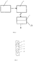
- FIG. 1 shows a detection device (1) which is coordinated by a system controller (2).
- the system control (2) acts on an energy supply (3) that feeds lighting (4).
- An optical sensor (5) is also monitored by the system controller (2).
- Output signals of the optical sensor (5) are fed to a brand recognition (6), which transmits their output signals to a brand identification (7).
- the optical sensor (5) and the mark recognition (6) are designed in triplicate.
- the brand recognition (6) and the brand identification (7) are also connected to the system control (2).
- a trademark registration (8) can be arranged spatially separate from the detection device (1).
- the brand registration (8) is transmitted the output data of the brand identification (7) via a connecting line (9). In principle, wireless transmission can also be implemented.
- Fig. 2 illustrates a possible geometric arrangement of three optical sensors (5), which are designed, for example, as cameras.
- the optical sensors (5) are arranged relative to a detection location (10) at which a workpiece (11) is located in such a way that a complete detection of the area required for the evaluation of the mark recognition is ensured. For example, it is contemplated to arrange the optical sensors (5) offset by 120 degrees relative to the detection location (10).
- the optical sensors (5) are connected to an image processing system (12) which essentially contains the system control (2), the brand recognition (6) and the brand identification (7). An arrangement of brand recognition (6) as part of the image processing system (12) together with the sensor system (5) is possible.
- the number of optical sensors (5) used depends on the prevailing environmental conditions, the size and arrangement of the marking and the workpiece (11) to be detected.
- Fig. 3 illustrates in a modified form the sequence of image processing as the first stage of identification, in which one or more optical sensors (5) transmit their information to the brand recognition (6).
- the brand image is analyzed and optimized and then used for brand identification (17).
- a resulting image is generated from several images, which includes the area of the workpiece (11) containing the marking. If the marking is arranged in the area of the workpiece (11), for example, in such a way that only part of the marking can be detected by an optical sensor (5) and the other part of the marking by another optical sensor (5), this partial information is used generates a new image that contains the entire marking.
- the image generated in this way is fed to the second stage of the brand identification (17) in order to carry out a recognition of the marking content and to carry out a corresponding decoding of the marking.
- the brand recognition (6) and part of the brand identification (17) thus represent the first stage of image processing and in the area of brand identification (17) the second stage of image recognition is implemented.
- the marking in the area of the workpiece (11) can be in the form of numbers, letters, codes or pictorial characters, for example.
- the illumination (4) generates sufficient brightness, and sufficient contrast is also provided for the recording system.
- the image sensor (5) is each provided with a brand recognition (6,7) provided so that this process can be carried out clearly in real time. The brand completion and brand identification can be processed without real-time connection.
- Fig. 4 shows a partial representation of a workpiece (11) which can be designed as a shaft or as a drill. Markings (13), which are designed as graphic elements, are arranged in the region of the workpiece (11).
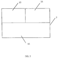
- FIG. 5 schematically shows the structure of the brand identification (7), which is equipped with a memory (15) for storing reference patterns, an analyzer (14) for comparing the reference patterns with the current image information and a working memory (16) for storing the current image information is.
- FIG. 6 and 7 schematically show the generation of a virtual new image in the brand identifier (7) as a result of the three images of the brand from the three brand identifications (6).
Abstract
Description
Die Erfindung betrifft eine Vorrichtung zur berührungslosen Erkennung von bewegten Objekten, insbesondere von Werkstücken, die mindestens einen optischen Sensor aufweist, der eine Markierung im Bereich des Objektes erfaßt und der mit einer Auswertungseinheit verbunden ist, die einen Analysator zur Auswertung einer erfaßten Markierung aufweist und bei der der Analysator mit einem Speicher verbunden ist, in dem Referenzmuster zur Analyse der erfaßten Markierungen abgespeichert sind.The invention relates to a device for contactless detection of moving objects, in particular workpieces, which has at least one optical sensor which detects a marking in the area of the object and which is connected to an evaluation unit which has an analyzer for evaluating a detected marking and at the analyzer is connected to a memory in which reference patterns for analyzing the detected markings are stored.
Ähnliche Vorrichtungen werden beispielsweise im Bereich des Einzelhandels eingesetzt, um einen Kassiervorgang zu beschleunigen. Auf den zu erkennenden Waren sind als Strichcode ausgebildete Markierungen angeordnet, wobei der Strichcode eine Information sowohl über die Art der Ware als auch über den Preis enthält. Mit Hilfe eines optischen Sensors wird dieser Strichcode erfaßt und über eine Auswertung wird der entsprechende Informationsinhalt ermittelt. Hierdurch ist es möglich, auf einem Kassenzettel sowohl eine Klartextangabe zur Art der Ware als auch den entsprechenden Preis auszudrucken. Ein Verfahren zur Erkennung eines derartigen Strichcodes ist in der EP-PS 0 408 126 beschrieben.Similar devices are used, for example, in the retail sector to speed up a checkout process. Markings designed as bar codes are arranged on the goods to be recognized, the bar code containing information both about the type of goods and about the price. With help of a optical sensor, this bar code is detected and the corresponding information content is determined via an evaluation. This makes it possible to print out both plain text on the type of goods and the corresponding price on a receipt. A method for recognizing such a bar code is described in EP-PS 0 408 126.
Ebenfalls spiegelt sich der vorveröffentlichte Stand der Technik in den Druckschriften DE 32 03 897 C2 und DE 36 23 519 A1 wieder. Die DE 32 03 897 C2 betrifft eine Vorrichtung zum Erkennen und Verarbeiten von Zeichen und/oder optischen Details. Bei dem in dieser Druckschrift beschriebenen direkten Verfahren identifiziert ein optischer Sensor mit Markenerkennung direkt die Marke im Bereich des Werkstückes und gibt sie zur Weiterverarbeitung als direkt ermitteltes und nicht virtuell erstelltes Bild der Marke weiter zur Analyse. Nicht enthalten ist in dieser Druckschrift eine Mehrfenstersteuerung, eine Markenidenifizierung über mindestens drei Bildsensoren, eine Auswertung der drei Einzelbilder, die Generierung eines virtuellen Bildes aus den Einzelbildern und eine anschließende Auswertung des virtuellen Markenbildes bezüglich des Markeninhaltes.The previously published prior art is also reflected in the documents DE 32 03 897 C2 and DE 36 23 519 A1. DE 32 03 897 C2 relates to a device for recognizing and processing characters and / or optical details. In the direct method described in this publication, an optical sensor with mark recognition directly identifies the mark in the area of the workpiece and passes it on for further processing as a directly determined and not virtually created image of the mark for analysis. This publication does not include a multi-window control, brand identification via at least three image sensors, evaluation of the three individual images, generation of a virtual image from the individual images and subsequent evaluation of the virtual brand image with regard to the brand content.
Die DE 36 23 519 A1 betriff eine Vorrichtung zur Erkennung und Verarbeitung von alphanumerischen Zeichen und Sonderzeichen in Blockschaltbildform. Die Druckschrift zeigt ein einstufiges Verfahren. Bezüglich der DE 32 03 879 C2 besteht eine Übereinstimmung dahingehend, daß eine alphanumerische Idenifizierung des Markeninhaltes durchgeführt wird.DE 36 23 519 A1 relates to a device for recognizing and processing alphanumeric characters and special characters in block diagram form. The publication shows a one-step process. With regard to DE 32 03 879 C2, there is agreement that alphanumeric identification of the brand content is carried out.
Im Bereich der Erkennung von Werkstücken, beispielsweise von Stangen und Wellen, die während einer Durchführung von Translations- sowie von Rotationsbewegungen erkannt werden sollen, ist ein leistungsfähiges Verfahren bislang nicht bekannt geworden. Die Erfassung von Markierungen im Bereich dieser Werkstücke erfolgt vielmehr statisch dadurch, daß die Bewegungen der Werkstücke gestoppt werden und im Stillstand die entsprechende Markierung gelesen wird. Überwiegend erfolgt diese Ablesung manuell durch eine Bedienperson. Im geringen Umfang sind auch bereits technische Hilfsmittel zur Durchführung des statischen Ablesevorganges eingesetzt worden.In the area of the detection of workpieces, such as rods and shafts, during a A powerful method has so far not become known for carrying out translation and rotational movements. Rather, the detection of markings in the area of these workpieces takes place statically in that the movements of the workpieces are stopped and the corresponding marking is read at a standstill. This reading is mostly done manually by an operator. To a small extent, technical aids have already been used to carry out the static reading process.
Eine Erfassung der Werkstücke in einem kontinuierlichen Betrieb ohne Durchführung von Anhaltevorgängen ist somit nicht möglich. Die manuelle Erfassung durch eine Bedienperson beinhaltet Fehlerrisiken, da sowohl ein Lesefehler erfolgen kann als auch bei einem richtigen Lesen das entsprechende Registrieren fehlerhaft durchgeführt werden kann.It is therefore not possible to record the workpieces in continuous operation without stopping. Manual recording by an operator involves risk of errors, since both a reading error can occur and, if read correctly, the corresponding registration can be carried out incorrectly.
Aufgabe der vorliegenden Erfindung ist es daher, eine Vorrichtung der einleitend genannten Art derart auszubilden, daß eine berührungslose Identifizierung und Registrierung bei bewegten Werkstücken durchgeführt werden kann, ohne daß eine Interaktion in den Transportvorgang der Werkstücke erfolgen muß.The object of the present invention is therefore to design a device of the type mentioned in the introduction in such a way that contactless identification and registration can be carried out on moving workpieces without any interaction in the transport process of the workpieces having to take place.
Diese Aufgabe wird erfindungsgemäß dadurch gelöst, daß eine Mehrstufensteuerung vorgesehen ist, die zunächst aus mehreren unterschiedlichen erfaßten Bildern ein die Markierung enthaltendes Bild generiert und anschließend dieses Bild zur Erkennung und Decodierung der Markierung auswertet, wobei zunächst überprüft wird, ob eines der Bilder die Markierung vollständig enthält und bei einem negativen Überprüfungsergebenis in den entstehenden erfaßten Bildern jeweils Teilbereiche der Markierung identifiziert und aus diesen Teilbereichen ein vollständiges Bild der Markierung generiert wird.This object is achieved according to the invention in that a multi-stage control is provided which first generates an image containing the marking from several different captured images and then evaluates this image for recognizing and decoding the marking, it being first checked whether one of the images completely completes the marking contains and in the event of a negative verification result in the resulting captured images in each case partial areas of the Mark is identified and a complete image of the marking is generated from these partial areas.
Durch die Mehrstufensteuerung ist es möglich, in den mehreren unterschiedlichen erfaßten Bildern zunächst diejenigen Bildstellen zu erkennen, die die Markierung beinhalten. Ggf. werden die in den jeweiligen Bildern enthaltenen Informationen so kombiniert, daß ein Bild entsteht, das die Markierung vollständig wiedergibt. Anschließend wird dieses mit der vollständigen Markierung versehene Bild decodiert und der entsprechende Informationsinhalt ausgewertet. Die Decodierung kann in einfacher Weise dadurch erfolgen, daß die erfaßte Markierung im Bereich des Komparators mit einem Referenzmuster verglichen wird. Dies ermöglicht es, eine sehr große Vielfalt von Markierungen zu verwenden. Beispielsweise ist es möglich, bildhafte Markierungen zu erfassen. Ebenfalls ist es möglich, Konturen zur Erkennung der Werkstücke auszuwerten.The multi-stage control makes it possible to first recognize those image locations which contain the marking in the several different captured images. Possibly. the information contained in the respective images is combined in such a way that an image is created which completely reproduces the marking. Then this image provided with the complete marking is decoded and the corresponding information content is evaluated. The decoding can be carried out in a simple manner by comparing the detected marking in the area of the comparator with a reference pattern. This enables a very wide variety of markings to be used. For example, it is possible to capture pictorial markings. It is also possible to evaluate contours to identify the workpieces.
Insbesondere ist daran gedacht, mehrere parallelarbeitende Bilderfassungseinheiten oder optische Sensoren zu verwenden, die jeweils einen Direktanschluß an eine erste Stufe der Analyseeinheit aufweisen. In der ersten Stufe der Analyseeinheit wird die optische Markierung erkannt. Die Erkennung der Markierung kann optional von allen parallelarbeitenden Analyseeinheiten der ersten Verarbeitungsstufe gleichgut durchgeführt werden. Hierdurch kann die Markierung mit ihrem Inhalt beliebig durch Auswahl aus einem einzelnen der drei Ergebnisse innerhalb der zweiten Analysestufe bezüglich des Markierungsinhaltes identifiziert werden.In particular, it is contemplated to use several image acquisition units or optical sensors operating in parallel, each of which has a direct connection to a first stage of the analysis unit. The optical marking is recognized in the first stage of the analysis unit. The detection of the marking can optionally be carried out equally well by all analysis units working in parallel in the first processing stage. As a result, the marking with its content can be identified as desired by selecting from a single one of the three results within the second analysis stage with regard to the marking content.
Werden nur Teile der Markierung erfaßt oder liegt eine schlechte Bildqualität vor, so kann durch die parallelarbeitende Bilderfassungeinheit mit direktem Analysatoranschluß für die Idenfikation der Markierung in der ersten Stufe eine Weiterverarbeitung erfolgen. Die Markierungen oder Teile der Markierungen werden erkannt und an die zweite Analysestufe übergeben. In der zweiten Analysestufe werden die Bilder aus den parallel in der ersten Stufe erfaßten Daten kombiniert und zu einem vollständigen Bild der Markierung zusammengefaßt. Anschließend wird das Verfahren fortgesetzt, wie bei einer ursprünglichen Erfassung einer vollständigen Markierung.If only parts of the marking are detected or if there is poor image quality, the parallel image acquisition unit with direct can Further connection of the analyzer for the identification of the marking in the first stage. The markings or parts of the markings are recognized and transferred to the second analysis stage. In the second analysis stage, the images from the data acquired in parallel in the first stage are combined and combined to form a complete image of the marking. The process then continues as in the case of an original detection of a complete marking.
Innerhalb der zwei Analysstufen können unterschiedliche Verfahren zum Einsatz kommen. In der ersten Stufe wird die optische Markierung erkannt, wobei ein Analyseverfahren zum Einsatz kommt, das der definierten Markierung optimal angepaßt ist. In der zweiten Stufe wird der Inhalt der Markierung, der aus beliebigen Zeichen bestehen kann, ebenfalls durch optimierte Analyseverfahren identifiziert. In beiden Stufen können Komparatorverfahren oder pixelbasierte beziehungsweise vektorbasierte Verfahren benutzt werden.Different methods can be used within the two analysis stages. In the first stage, the optical marking is recognized, using an analysis method that is optimally adapted to the defined marking. In the second stage, the content of the marking, which can consist of any characters, is also identified using optimized analysis methods. Comparator methods or pixel-based or vector-based methods can be used in both stages.
Zur Gewährleistung einer sicheren Erfassung der Markierung bei unterschiedlichen Einsatzbedingungen wird vorgeschlagen, daß zur Helligkeitsvorgabe im Bereich des Werkstückes im Bereich der optischen Sensoren eine Beleuchtung angeordnet ist.In order to ensure reliable detection of the marking under different operating conditions, it is proposed that lighting be arranged in the area of the workpiece in the area of the optical sensors in order to specify the brightness.
Eine zweckmäßige Realisierung besteht darin, daß mindestens einer der optischen Sensoren als eine Kamera ausgebildet ist.An expedient implementation is that at least one of the optical sensors is designed as a camera.
Zur Ermöglichung einer Erfassung der Markierung bei unterschiedlichen Orientierungen des Werkstückes wird vorgeschlagen, daß drei Sensoren vorgesehen sind.To enable detection of the marking in the case of different orientations of the workpiece, it is proposed that three sensors be provided.
Eine zeitgleiche Erfassung unterschiedlicher Ansichten des Werkstückes wird dadurch ermöglicht, daß im Bereich eines Erfassungsortes mehrere optische Sensoren relativ zum Werkstück mit unterschiedlichen Erfassungsrichtungen angeordnet sind.Simultaneous detection of different views of the workpiece is made possible in that several optical sensors are arranged relative to the workpiece with different detection directions in the area of a detection location.
Zur vollständigen bildlichen Erfassung des Werkstückes ist es ausreichend, daß die Sensoren relativ zum Erfassungsort soweit versetzt zueinander angeordnet sind, daß eine lückenlose Erfassung realisiert ist.For complete image detection of the workpiece, it is sufficient for the sensors to be arranged so far from one another relative to the detection location that gapless detection is realized.
In der Zeichnung sind Ausführungsbeispiele der Erfindung schematisch dargestellt. Es zeigen:
- Fig. 1:
- ein vereinfachtes Funktionsdiagramm zur Veranschaulichung der Verfahrensabläufe,
- Fig. 2
- eine Skizze zur Veranschaulichung einer räumlichen Anordnung von drei optischen Sensoren,
- Fig. 3
- ein Blockschaltbild zur Veranschaulichung der Mehrstufensteuerung bei der Auswertung der Markierung,
- Fig. 4
- eine teilweise Darstellung eines als Welle ausgebildeten Werkstückes mit bildlichen Markierungen,
- Fig. 5
- eine schematische Darstellung der Markenidentifizierung,
- Fig. 6
- eine Skizze zur Veranschaulichung einer Kombination von Teilinformationen zu einem virtuellen Bild und
- Fig. 7
- eine Skizze zur Veranschaulichung einer anderen Kombinationsvariante.
- Fig. 1:
- a simplified functional diagram to illustrate the process sequences,
- Fig. 2
- a sketch to illustrate a spatial arrangement of three optical sensors,
- Fig. 3
- 2 shows a block diagram to illustrate the multi-stage control when evaluating the marking,
- Fig. 4
- 1 shows a partial representation of a workpiece designed as a shaft with pictorial markings,
- Fig. 5
- a schematic representation of the brand identification,
- Fig. 6
- a sketch to illustrate a combination of partial information to a virtual image and
- Fig. 7
- a sketch to illustrate another combination variant.
In Fig. 1 ist eine Erfassungseinrichtung (1) dargestellt, die von einer Systemsteuerung (2) koordiniert wird. Die Systemsteuerung (2) wirkt auf eine Energieversorgung (3) ein, die eine Beleuchtung (4) speist. Ebenfalls wird ein optischer Sensor (5) von der Systemsteuerung (2) überwacht. Ausgangssignale des optischen Sensors (5) werden einer Markenerkennung (6) zugeführt, die ihre Ausgangssignale an eine Markenidentifizierung (7) übermittelt. Der optische Sensor (5) und die Markenerkennung (6) sind dreifach ausgeführt. Auch die Markenerkennung (6) und die Markenidentifizierung (7) sind mit der Systemsteuerung (2) verbunden. Räumlich getrennt zur Erfassungseinrichtung (1) kann eine Markenregistrierung (8) angeordnet sein. Der Markenregistrierung (8) werden die Ausgangsdaten der Markenidentifizierung (7) über eine Anschlußleitung (9) übermittelt. Grundsätzlich ist auch eine drahtlose Übermittlung realisierbar.1 shows a detection device (1) which is coordinated by a system controller (2). The system control (2) acts on an energy supply (3) that feeds lighting (4). An optical sensor (5) is also monitored by the system controller (2). Output signals of the optical sensor (5) are fed to a brand recognition (6), which transmits their output signals to a brand identification (7). The optical sensor (5) and the mark recognition (6) are designed in triplicate. The brand recognition (6) and the brand identification (7) are also connected to the system control (2). A trademark registration (8) can be arranged spatially separate from the detection device (1). The brand registration (8) is transmitted the output data of the brand identification (7) via a connecting line (9). In principle, wireless transmission can also be implemented.
Fig. 2 veranschaulicht eine mögliche geometrische Anordnung von drei optischen Sensoren (5), die beispielsweise als Kameras ausgebildet sind. Die optischen Sensoren (5) sind relativ zu einem Erfassungsort (10), an dem sich ein Werkstück (11) befindet, derart angeordnet, daß eine vollständige Erfassung des für die Auswertung der Markenerkennung erforderlicher Bereiches sichergestellt ist. Beispielsweise ist daran gedacht, die optischen Sensoren (5) relativ zum Erfassungsort (10) um 120 Grad versetzt anzuordnen. Die optischen Sensoren (5) sind an ein Bildverarbeitungssystem (12) angeschlossen, das im wesentlichen die Systemsteuerung (2), die Markenerkennung (6) und die Markenidentifizierung (7) beinhaltet. Eine Anordnung der Markenerkennung (6) als Teil der Bildverarbeitungssystems (12) räumlich zusammen mit dem Sensorsystem (5) ist möglich.Fig. 2 illustrates a possible geometric arrangement of three optical sensors (5), which are designed, for example, as cameras. The optical sensors (5) are arranged relative to a detection location (10) at which a workpiece (11) is located in such a way that a complete detection of the area required for the evaluation of the mark recognition is ensured. For example, it is contemplated to arrange the optical sensors (5) offset by 120 degrees relative to the detection location (10). The optical sensors (5) are connected to an image processing system (12) which essentially contains the system control (2), the brand recognition (6) and the brand identification (7). An arrangement of brand recognition (6) as part of the image processing system (12) together with the sensor system (5) is possible.
Die Anzahl der verwendeten optischen Sensoren (5) ist abhängig von den jeweils vorliegenden Umgebungsbedingungen, der Größe und der Anordnung der Markierung sowie dem zu erfassenden Werkstück (11).The number of optical sensors (5) used depends on the prevailing environmental conditions, the size and arrangement of the marking and the workpiece (11) to be detected.
Fig. 3 veranschaulicht in modifizierter Form nochmals den Ablauf der Bildverarbeitung als erste Stufe der Identifizierung, bei der einer oder mehrere optischen Sensoren (5) ihre Informationen an die Markenerkennung (6) übermitteln. Das Markenbild wird analysiert und optimiert und anschließend der Markenidentifzierung (17) zugeführt. Hier wird aus mehreren Bildern ein resultierendes Bild generiert, das den die Markierung enthaltenden Bereich des Werkstückes (11) umfaßt. Ist die Markierung im Bereich des Werkstückes (11) beispielsweise so angeordnet, daß nur ein Teil der Markierung von einem optischen Sensor (5) und der andere Teil der Markierung von einem anderen optischen Sensor (5) erfaßbar ist, so wird aus diesen Teilinformationen ein neues Bild generiert, das die Markierung komplett enthält.Fig. 3 illustrates in a modified form the sequence of image processing as the first stage of identification, in which one or more optical sensors (5) transmit their information to the brand recognition (6). The brand image is analyzed and optimized and then used for brand identification (17). A resulting image is generated from several images, which includes the area of the workpiece (11) containing the marking. If the marking is arranged in the area of the workpiece (11), for example, in such a way that only part of the marking can be detected by an optical sensor (5) and the other part of the marking by another optical sensor (5), this partial information is used generates a new image that contains the entire marking.
Das derart generierte Bild wird der zweiten Stufe der Markenidentifizierung (17) zugeführt, um hier eine Erkennung des Markierungsinhaltes durchzuführen und eine entsprechende Decodierung der Markierung vorzunehmen.The image generated in this way is fed to the second stage of the brand identification (17) in order to carry out a recognition of the marking content and to carry out a corresponding decoding of the marking.
Die Markenerkennung (6) und ein Teil der Markenidentifizierung (17) stellen somit die erste Stufe der Bildverarbeitung dar und im Bereich der Markenidentifizierung (17) ist die zweite Stufe der Bilderkennung realisiert.The brand recognition (6) and part of the brand identification (17) thus represent the first stage of image processing and in the area of brand identification (17) the second stage of image recognition is implemented.
Die Markierung im Bereich des Werkstückes (11) kann beispielsweise in Form von Zahlen, Buchstaben, Codes oder bildlichen Zeichen ausgebildet sein. Zur Gewährleistung einer ausreichend klaren Erkennung der Markierung wird durch die Beleuchtung (4) eine ausreichende Helligkeit erzeugt, ebenfalls wird für einen ausreichenden Kontrast für das Aufnahmesystem gesorgt.The marking in the area of the workpiece (11) can be in the form of numbers, letters, codes or pictorial characters, for example. To ensure that the marking is recognized sufficiently clearly, the illumination (4) generates sufficient brightness, and sufficient contrast is also provided for the recording system.
Durch die Aufteilung der Bildverarbeitung auf die Markenerkennung (6) und die Markenidentifizierung (7) zusammen mit dem Bildsensor (5) und der Markenidentifizierung (17) sowie aufgrund der entsprechenden Abspeicherung der Merkmale ist es möglich, eine hohe Verarbeitungsgeschwindigkeit zu realisieren, da es vorgesehen ist, Muster- und Strukturvergleiche durchzuführen. Die Verarbeitungsgeschwindigkeit wird auch dadurch erhöht, daß der Mustervergleich mit Hilfe von abgespeicherten Grundmustern durchgeführt wird. Ebenfalls ist es möglich, zur Adaption des Systems an jeweils vorhandene Markierungen einen Lernprozeß durchzuführen, in dem die vorliegenden charakteristischen Muster erfaßt werden.By dividing the image processing into the brand recognition (6) and the brand identification (7) together with the image sensor (5) and the brand identification (17) and due to the corresponding storage of the features, it is possible to realize a high processing speed because it is provided is to carry out pattern and structure comparisons. The processing speed is also increased in that the pattern comparison is carried out with the aid of stored basic patterns. It is also possible to carry out a learning process in order to adapt the system to the markings in each case, in which the present characteristic patterns are recorded.
Zur Gewährleistung einer hohen Verarbeitungsgeschwindigkeit ist insbesondere daran gedacht, mehrere optische Sensoren (5) aus unterschiedlichen Blickwinkeln auf das zu erfassende Werkstück (11) zu richten und gleichzeitig Bildinformationen des Werkstückes (11) aus unterschiedlichen Blickwinkeln zu generieren. Hierdurch ist sichergestellt, daß zum Erfassungszeitpunkt eine Bildinformation der vollständigen Markierung vorliegt. Aus diesen tatsächlich vorliegenden perspektivischen Ansichten des Werkstückes (11) wird dann virtuell eine Ansicht generiert, die die Markierung vollständig wiedergibt. Zu diesem Zweck ist der Bildsensor (5) jeweils mit einer Markenerkennung (6,7) versehen, so daß dieser Vorgang eindeutig in Realzeit durchgeführt werden kann. Die Markenkomplettierung und Markenidentifizierung kann ohne Realzeitanbindung nachverarbeitet werden.To ensure a high processing speed, it is particularly intended to point several optical sensors (5) from different angles at the workpiece (11) to be detected and at the same time to generate image information of the workpiece (11) from different angles. This ensures that there is image information of the complete marking at the time of detection. From these actually existing perspective views of the workpiece (11), a view is then virtually generated which reproduces the marking completely. For this purpose, the image sensor (5) is each provided with a brand recognition (6,7) provided so that this process can be carried out clearly in real time. The brand completion and brand identification can be processed without real-time connection.
Grundsätzlich ist es ebenfalls denkbar, lediglich einen optischen Sensor (5) zu verwenden und zeitlich nacheinander mehrere Bilder zu generieren und diese anschließend zu kombinieren. Aufgrund der erforderlichen Erfassungszeit kommt ein derartiger Ablauf jedoch nur dann in Betracht, wenn die Rotationsgeschwindigkeit der Objekte relativ zu ihrer translatorischen Bewegung hoch ist. Ein weiteres Anwendungsgebiet besteht dann, wenn die optischen Sensoren (5) nicht räumlich fixiert sind, sondern beispielsweise durch Drehung den translatorischen Bewegungen der Werkstücke (11) entlang einer bestimmten Wegstrecke folgen können.In principle, it is also conceivable to use only one optical sensor (5) and to generate several images one after the other and then to combine them. However, due to the required acquisition time, such a sequence can only be considered if the rotational speed of the objects is high relative to their translational movement. Another area of application is when the optical sensors (5) are not spatially fixed, but rather can follow the translational movements of the workpieces (11) along a certain path, for example by rotation.
Fig. 4 zeigt eine teilweise Darstellung eines Werkstückes (11), das als Welle oder als Bohrer ausgebildet sein kann. Im Bereich des Werkstückes (11) sind Markierungen (13) angeordnet, die als grafische Elemente ausgebildet sind.Fig. 4 shows a partial representation of a workpiece (11) which can be designed as a shaft or as a drill. Markings (13), which are designed as graphic elements, are arranged in the region of the workpiece (11).
Fig. 5 zeigt schematisch den Aufbau der Markenidentifizierung (7), die mit einem Speicher (15) zur Bevorratung von Referenzmustern, einem Analysator (14) zum Vergleich der Referenzmuster mit den aktuellen Bildinformationen und einem Arbeitsspeicher (16) zur Bevorratung der aktuellen Bildinformationen ausgestattet ist.5 schematically shows the structure of the brand identification (7), which is equipped with a memory (15) for storing reference patterns, an analyzer (14) for comparing the reference patterns with the current image information and a working memory (16) for storing the current image information is.
Fig. 6 und Fig. 7 zeigen schematisch die Generierung eines virtuellen neuen Bildes im Markenidentifizierer (7) als Ergebnis aus den drei Bildern der Marke aus den drei Markenerkennungen (6).6 and 7 schematically show the generation of a virtual new image in the brand identifier (7) as a result of the three images of the brand from the three brand identifications (6).
Claims (9)
Applications Claiming Priority (2)
| Application Number | Priority Date | Filing Date | Title |
|---|---|---|---|
| DE19508024 | 1995-03-07 | ||
| DE19508024A DE19508024C2 (en) | 1995-03-07 | 1995-03-07 | Non-contact detection device |
Publications (3)
| Publication Number | Publication Date |
|---|---|
| EP0731416A2 true EP0731416A2 (en) | 1996-09-11 |
| EP0731416A3 EP0731416A3 (en) | 1998-01-21 |
| EP0731416B1 EP0731416B1 (en) | 2002-09-04 |
Family
ID=7755909
Family Applications (1)
| Application Number | Title | Priority Date | Filing Date |
|---|---|---|---|
| EP96103329A Expired - Lifetime EP0731416B1 (en) | 1995-03-07 | 1996-03-04 | Contactless detection device |
Country Status (2)
| Country | Link |
|---|---|
| EP (1) | EP0731416B1 (en) |
| DE (2) | DE19508024C2 (en) |
Cited By (2)
| Publication number | Priority date | Publication date | Assignee | Title |
|---|---|---|---|---|
| US6844286B2 (en) | 2002-07-31 | 2005-01-18 | Umicore Ag & Co. Kg | Water-based catalyst inks and their use for manufacture of catalyst-coated substrates |
| EP3399335A1 (en) * | 2017-05-03 | 2018-11-07 | Sick AG | Contrast sensor |
Families Citing this family (1)
| Publication number | Priority date | Publication date | Assignee | Title |
|---|---|---|---|---|
| DE10050368A1 (en) | 2000-10-11 | 2002-04-18 | Sick Ag | Device and method for recognizing codes |
Citations (7)
| Publication number | Priority date | Publication date | Assignee | Title |
|---|---|---|---|---|
| JPS58123164A (en) * | 1982-01-14 | 1983-07-22 | Sumitomo Light Metal Ind Ltd | Detector for marked part of tube material of wire |
| DE3623519A1 (en) * | 1986-07-11 | 1988-01-21 | Helmut A Kappner | Method for automatically recognising characters |
| DE3630202A1 (en) * | 1986-09-04 | 1988-03-10 | Karl F Zimmer Kg | Electro-optical scanning device for a bar code, in which the bars are constructed as raised ribs |
| DE3203897C2 (en) * | 1981-11-07 | 1988-04-21 | Licentia Patent-Verwaltungs-Gmbh, 6000 Frankfurt, De | |
| US4973829A (en) * | 1988-11-22 | 1990-11-27 | Eastman Kodak Company | Bar code reading method |
| US4982438A (en) * | 1987-06-02 | 1991-01-01 | Hitachi, Ltd. | Apparatus and method for recognizing three-dimensional shape of object |
| EP0436072A2 (en) * | 1990-01-05 | 1991-07-10 | Symbol Technologies, Inc. | Method of decoding bar code symbols from partial scans |
Family Cites Families (1)
| Publication number | Priority date | Publication date | Assignee | Title |
|---|---|---|---|---|
| NL8901759A (en) * | 1989-07-10 | 1991-02-01 | Nederland Ptt | METHOD FOR DETECTING A BAR CODE |
-
1995
- 1995-03-07 DE DE19508024A patent/DE19508024C2/en not_active Expired - Fee Related
-
1996
- 1996-03-04 DE DE59609614T patent/DE59609614D1/en not_active Expired - Fee Related
- 1996-03-04 EP EP96103329A patent/EP0731416B1/en not_active Expired - Lifetime
Patent Citations (7)
| Publication number | Priority date | Publication date | Assignee | Title |
|---|---|---|---|---|
| DE3203897C2 (en) * | 1981-11-07 | 1988-04-21 | Licentia Patent-Verwaltungs-Gmbh, 6000 Frankfurt, De | |
| JPS58123164A (en) * | 1982-01-14 | 1983-07-22 | Sumitomo Light Metal Ind Ltd | Detector for marked part of tube material of wire |
| DE3623519A1 (en) * | 1986-07-11 | 1988-01-21 | Helmut A Kappner | Method for automatically recognising characters |
| DE3630202A1 (en) * | 1986-09-04 | 1988-03-10 | Karl F Zimmer Kg | Electro-optical scanning device for a bar code, in which the bars are constructed as raised ribs |
| US4982438A (en) * | 1987-06-02 | 1991-01-01 | Hitachi, Ltd. | Apparatus and method for recognizing three-dimensional shape of object |
| US4973829A (en) * | 1988-11-22 | 1990-11-27 | Eastman Kodak Company | Bar code reading method |
| EP0436072A2 (en) * | 1990-01-05 | 1991-07-10 | Symbol Technologies, Inc. | Method of decoding bar code symbols from partial scans |
Non-Patent Citations (1)
| Title |
|---|
| PATENT ABSTRACTS OF JAPAN vol. 7, no. 234 (P-230) [1379] , 18.Oktober 1983 & JP 58 123164 A (SUMITOMO KEIKINZOKU KOGYO K.K.), 22.Juli 1983, * |
Cited By (3)
| Publication number | Priority date | Publication date | Assignee | Title |
|---|---|---|---|---|
| US6844286B2 (en) | 2002-07-31 | 2005-01-18 | Umicore Ag & Co. Kg | Water-based catalyst inks and their use for manufacture of catalyst-coated substrates |
| EP3399335A1 (en) * | 2017-05-03 | 2018-11-07 | Sick AG | Contrast sensor |
| US10726288B2 (en) | 2017-05-03 | 2020-07-28 | Sick Ag | Contrast sensor |
Also Published As
| Publication number | Publication date |
|---|---|
| DE19508024A1 (en) | 1996-09-12 |
| EP0731416B1 (en) | 2002-09-04 |
| DE59609614D1 (en) | 2002-10-10 |
| EP0731416A3 (en) | 1998-01-21 |
| DE19508024C2 (en) | 1996-12-19 |
Similar Documents
| Publication | Publication Date | Title |
|---|---|---|
| DE4000603C2 (en) | Method and device for temporarily storing objects such as letters or the like. in a reading system | |
| EP2128793B1 (en) | Method and device for inspecting print products, computer program and computer program product | |
| DE10034606B4 (en) | Method for providing manufacturing-related data in a series production of manufacturing objects, in particular motor vehicles | |
| EP0752137B1 (en) | Identification and control system for processed and/or transported goods | |
| EP0356705B1 (en) | Data reading unit for an ink control devices | |
| EP0731416B1 (en) | Contactless detection device | |
| DE3414455C2 (en) | Method and device for reading and processing information consisting of decodable font information and / or non-decodable graphic information | |
| DE4211171C2 (en) | Process for recognizing patterns of interest | |
| EP1389493A1 (en) | Process and apparatus for automatic marking of address fields | |
| EP1139285B1 (en) | Method and apparatus for testing or inspection of articles | |
| EP1229483B1 (en) | Method and apparatus for reading parceladdresses with postcodes | |
| DE10137093A1 (en) | Recognition of a code, particularly a two-dimensional matrix type code, within a graphical background or image whereby recognition is undertaken using a neuronal network | |
| DE3903595A1 (en) | Method for reading bar codes | |
| EP1229484B1 (en) | Method and apparatus for reading parcel addresses with postcodes | |
| DE19507059B4 (en) | Method for omnidirectional detection of OCR plain text on labels or similar data carriers by random search and decoding with a neural network | |
| WO2014082799A1 (en) | Method and device for testing a laser marking produced in accordance with an angle on a document surface | |
| DE10064226B4 (en) | Method and apparatus for reading postal codes from addresses on broadcasts | |
| EP1116162B1 (en) | Method for reading a bar code | |
| DE2055786B2 (en) | Device for optical character recognition | |
| DD251014A1 (en) | METHOD AND DEVICE FOR VISUALLY DETECTING AND MEASURING MARKINGS AND WORKPIECES IN THE CONTINUOUS MATERIAL FLOW FOR CONTROLLING AND RELEASING PROCESSING PROCESSES | |
| DE3723785A1 (en) | METHOD AND DEVICE FOR OPTICALLY SCANNING A DOCUMENT | |
| DE10104425A1 (en) | Device for identification of faults in painted surfaces and similar incorporates at least one optical photography system producing at least two pictures of different resolutions of object | |
| EP1083421A2 (en) | Arrangement for identifying motor vehicles during their examination in a vehicle test track | |
| DE3147225A1 (en) | Method and device for reading contrasting characters | |
| DE4334883A1 (en) | Method and device for monitoring recording instruments or graphic output units, in particular in plotters, recording devices or similar automatically operating systems |
Legal Events
| Date | Code | Title | Description |
|---|---|---|---|
| PUAI | Public reference made under article 153(3) epc to a published international application that has entered the european phase |
Free format text: ORIGINAL CODE: 0009012 |
|
| AK | Designated contracting states |
Kind code of ref document: A2 Designated state(s): CH DE DK FR GB IT LI NL SE |
|
| PUAL | Search report despatched |
Free format text: ORIGINAL CODE: 0009013 |
|
| AK | Designated contracting states |
Kind code of ref document: A3 Designated state(s): CH DE DK FR GB IT LI NL SE |
|
| 17P | Request for examination filed |
Effective date: 19971211 |
|
| GRAG | Despatch of communication of intention to grant |
Free format text: ORIGINAL CODE: EPIDOS AGRA |
|
| GRAG | Despatch of communication of intention to grant |
Free format text: ORIGINAL CODE: EPIDOS AGRA |
|
| GRAH | Despatch of communication of intention to grant a patent |
Free format text: ORIGINAL CODE: EPIDOS IGRA |
|
| 17Q | First examination report despatched |
Effective date: 20020228 |
|
| RAP1 | Party data changed (applicant data changed or rights of an application transferred) |
Owner name: ASTRIUM GMBH |
|
| GRAH | Despatch of communication of intention to grant a patent |
Free format text: ORIGINAL CODE: EPIDOS IGRA |
|
| GRAA | (expected) grant |
Free format text: ORIGINAL CODE: 0009210 |
|
| AK | Designated contracting states |
Kind code of ref document: B1 Designated state(s): CH DE DK FR GB IT LI NL SE |
|
| PG25 | Lapsed in a contracting state [announced via postgrant information from national office to epo] |
Ref country code: NL Free format text: LAPSE BECAUSE OF FAILURE TO SUBMIT A TRANSLATION OF THE DESCRIPTION OR TO PAY THE FEE WITHIN THE PRESCRIBED TIME-LIMIT Effective date: 20020904 Ref country code: IT Free format text: LAPSE BECAUSE OF FAILURE TO SUBMIT A TRANSLATION OF THE DESCRIPTION OR TO PAY THE FEE WITHIN THE PRE;WARNING: LAPSES OF ITALIAN PATENTS WITH EFFECTIVE DATE BEFORE 2007 MAY HAVE OCCURRED AT ANY TIME BEFORE 2007. THE CORRECT EFFECTIVE DATE MAY BE DIFFERENT FROM THE ONE RECORDED.SCRIBED TIME-LIMIT Effective date: 20020904 Ref country code: GB Free format text: LAPSE BECAUSE OF FAILURE TO SUBMIT A TRANSLATION OF THE DESCRIPTION OR TO PAY THE FEE WITHIN THE PRESCRIBED TIME-LIMIT Effective date: 20020904 Ref country code: FR Free format text: LAPSE BECAUSE OF NON-PAYMENT OF DUE FEES Effective date: 20020904 |
|
| REG | Reference to a national code |
Ref country code: GB Ref legal event code: FG4D Free format text: NOT ENGLISH |
|
| REG | Reference to a national code |
Ref country code: CH Ref legal event code: EP |
|
| REF | Corresponds to: |
Ref document number: 59609614 Country of ref document: DE Date of ref document: 20021010 |
|
| PG25 | Lapsed in a contracting state [announced via postgrant information from national office to epo] |
Ref country code: SE Free format text: LAPSE BECAUSE OF FAILURE TO SUBMIT A TRANSLATION OF THE DESCRIPTION OR TO PAY THE FEE WITHIN THE PRESCRIBED TIME-LIMIT Effective date: 20021204 Ref country code: DK Free format text: LAPSE BECAUSE OF FAILURE TO SUBMIT A TRANSLATION OF THE DESCRIPTION OR TO PAY THE FEE WITHIN THE PRESCRIBED TIME-LIMIT Effective date: 20021204 |
|
| NLV1 | Nl: lapsed or annulled due to failure to fulfill the requirements of art. 29p and 29m of the patents act | ||
| PGFP | Annual fee paid to national office [announced via postgrant information from national office to epo] |
Ref country code: DE Payment date: 20030227 Year of fee payment: 8 |
|
| GBV | Gb: ep patent (uk) treated as always having been void in accordance with gb section 77(7)/1977 [no translation filed] |
Effective date: 20020904 |
|
| PG25 | Lapsed in a contracting state [announced via postgrant information from national office to epo] |
Ref country code: LI Free format text: LAPSE BECAUSE OF NON-PAYMENT OF DUE FEES Effective date: 20030331 Ref country code: CH Free format text: LAPSE BECAUSE OF NON-PAYMENT OF DUE FEES Effective date: 20030331 |
|
| EN | Fr: translation not filed | ||
| PLBE | No opposition filed within time limit |
Free format text: ORIGINAL CODE: 0009261 |
|
| STAA | Information on the status of an ep patent application or granted ep patent |
Free format text: STATUS: NO OPPOSITION FILED WITHIN TIME LIMIT |
|
| 26N | No opposition filed |
Effective date: 20030605 |
|
| REG | Reference to a national code |
Ref country code: CH Ref legal event code: PL |
|
| PG25 | Lapsed in a contracting state [announced via postgrant information from national office to epo] |
Ref country code: DE Free format text: LAPSE BECAUSE OF NON-PAYMENT OF DUE FEES Effective date: 20041001 |