EP0743056A2 - Hydrotherapy device for massaging the human body - Google Patents
Hydrotherapy device for massaging the human body Download PDFInfo
- Publication number
- EP0743056A2 EP0743056A2 EP96440045A EP96440045A EP0743056A2 EP 0743056 A2 EP0743056 A2 EP 0743056A2 EP 96440045 A EP96440045 A EP 96440045A EP 96440045 A EP96440045 A EP 96440045A EP 0743056 A2 EP0743056 A2 EP 0743056A2
- Authority
- EP
- European Patent Office
- Prior art keywords
- chamber
- water
- hydrotherapy device
- hydrotherapy
- nozzle
- Prior art date
- Legal status (The legal status is an assumption and is not a legal conclusion. Google has not performed a legal analysis and makes no representation as to the accuracy of the status listed.)
- Withdrawn
Links
Images

Classifications
-
- B—PERFORMING OPERATIONS; TRANSPORTING
- B05—SPRAYING OR ATOMISING IN GENERAL; APPLYING FLUENT MATERIALS TO SURFACES, IN GENERAL
- B05B—SPRAYING APPARATUS; ATOMISING APPARATUS; NOZZLES
- B05B1/00—Nozzles, spray heads or other outlets, with or without auxiliary devices such as valves, heating means
- B05B1/34—Nozzles, spray heads or other outlets, with or without auxiliary devices such as valves, heating means designed to influence the nature of flow of the liquid or other fluent material, e.g. to produce swirl
- B05B1/3405—Nozzles, spray heads or other outlets, with or without auxiliary devices such as valves, heating means designed to influence the nature of flow of the liquid or other fluent material, e.g. to produce swirl to produce swirl
- B05B1/341—Nozzles, spray heads or other outlets, with or without auxiliary devices such as valves, heating means designed to influence the nature of flow of the liquid or other fluent material, e.g. to produce swirl to produce swirl before discharging the liquid or other fluent material, e.g. in a swirl chamber upstream the spray outlet
- B05B1/3415—Nozzles, spray heads or other outlets, with or without auxiliary devices such as valves, heating means designed to influence the nature of flow of the liquid or other fluent material, e.g. to produce swirl to produce swirl before discharging the liquid or other fluent material, e.g. in a swirl chamber upstream the spray outlet with swirl imparting inserts upstream of the swirl chamber
-
- A—HUMAN NECESSITIES
- A61—MEDICAL OR VETERINARY SCIENCE; HYGIENE
- A61H—PHYSICAL THERAPY APPARATUS, e.g. DEVICES FOR LOCATING OR STIMULATING REFLEX POINTS IN THE BODY; ARTIFICIAL RESPIRATION; MASSAGE; BATHING DEVICES FOR SPECIAL THERAPEUTIC OR HYGIENIC PURPOSES OR SPECIFIC PARTS OF THE BODY
- A61H9/00—Pneumatic or hydraulic massage
-
- B—PERFORMING OPERATIONS; TRANSPORTING
- B05—SPRAYING OR ATOMISING IN GENERAL; APPLYING FLUENT MATERIALS TO SURFACES, IN GENERAL
- B05B—SPRAYING APPARATUS; ATOMISING APPARATUS; NOZZLES
- B05B1/00—Nozzles, spray heads or other outlets, with or without auxiliary devices such as valves, heating means
- B05B1/12—Nozzles, spray heads or other outlets, with or without auxiliary devices such as valves, heating means capable of producing different kinds of discharge, e.g. either jet or spray
-
- B—PERFORMING OPERATIONS; TRANSPORTING
- B05—SPRAYING OR ATOMISING IN GENERAL; APPLYING FLUENT MATERIALS TO SURFACES, IN GENERAL
- B05B—SPRAYING APPARATUS; ATOMISING APPARATUS; NOZZLES
- B05B1/00—Nozzles, spray heads or other outlets, with or without auxiliary devices such as valves, heating means
- B05B1/14—Nozzles, spray heads or other outlets, with or without auxiliary devices such as valves, heating means with multiple outlet openings; with strainers in or outside the outlet opening
- B05B1/16—Nozzles, spray heads or other outlets, with or without auxiliary devices such as valves, heating means with multiple outlet openings; with strainers in or outside the outlet opening having selectively- effective outlets
- B05B1/1627—Nozzles, spray heads or other outlets, with or without auxiliary devices such as valves, heating means with multiple outlet openings; with strainers in or outside the outlet opening having selectively- effective outlets with a selecting mechanism comprising a gate valve, a sliding valve or a cock
- B05B1/1636—Nozzles, spray heads or other outlets, with or without auxiliary devices such as valves, heating means with multiple outlet openings; with strainers in or outside the outlet opening having selectively- effective outlets with a selecting mechanism comprising a gate valve, a sliding valve or a cock by relative rotative movement of the valve elements
- B05B1/1645—Nozzles, spray heads or other outlets, with or without auxiliary devices such as valves, heating means with multiple outlet openings; with strainers in or outside the outlet opening having selectively- effective outlets with a selecting mechanism comprising a gate valve, a sliding valve or a cock by relative rotative movement of the valve elements the outlets being rotated during selection
- B05B1/1654—Nozzles, spray heads or other outlets, with or without auxiliary devices such as valves, heating means with multiple outlet openings; with strainers in or outside the outlet opening having selectively- effective outlets with a selecting mechanism comprising a gate valve, a sliding valve or a cock by relative rotative movement of the valve elements the outlets being rotated during selection about an axis parallel to the liquid passage in the stationary valve element
-
- A—HUMAN NECESSITIES
- A61—MEDICAL OR VETERINARY SCIENCE; HYGIENE
- A61H—PHYSICAL THERAPY APPARATUS, e.g. DEVICES FOR LOCATING OR STIMULATING REFLEX POINTS IN THE BODY; ARTIFICIAL RESPIRATION; MASSAGE; BATHING DEVICES FOR SPECIAL THERAPEUTIC OR HYGIENIC PURPOSES OR SPECIFIC PARTS OF THE BODY
- A61H2201/00—Characteristics of apparatus not provided for in the preceding codes
- A61H2201/50—Control means thereof
- A61H2201/5053—Control means thereof mechanically controlled
-
- B—PERFORMING OPERATIONS; TRANSPORTING
- B05—SPRAYING OR ATOMISING IN GENERAL; APPLYING FLUENT MATERIALS TO SURFACES, IN GENERAL
- B05B—SPRAYING APPARATUS; ATOMISING APPARATUS; NOZZLES
- B05B15/00—Details of spraying plant or spraying apparatus not otherwise provided for; Accessories
- B05B15/60—Arrangements for mounting, supporting or holding spraying apparatus
- B05B15/65—Mounting arrangements for fluid connection of the spraying apparatus or its outlets to flow conduits
Definitions
- the present invention relates to a hydrotherapy device for massaging the human body.
- This type of therapy is used more and more in order to carry out the desired massage by means of water jets, more or less powerful.
- Massage can also be used in the case of deficient muscles in order to stimulate certain soft masses.
- the massage can be carried out as a preventive measure for private use or in addition to medical treatment.
- the devices generally known for obtaining these massages by hydrotherapy consist, in domestic installations, of hand showers with adjustable jets, but their effectiveness is reduced because the force of expulsion of the water is limited to the nominal value of the pressure of the primary supply network. However, the hydromassage effort is only obtained beyond this value.
- a hydrotherapy device in particular for the treatment of vertebral pain, composed of a tubular frame equipped with nozzles for spraying water from a hot water - cold water supply network.
- this device is very limited, in terms of the massage possibilities it is able to offer, not to mention that its effectiveness remains, here again, very reduced due to insufficient water pressure provided. by nozzles could not be more conventional.
- a hydromassage machine capable of equipping a shower cabin and comprising a tubular structure in the form of a cage, in particular the uprights are equipped with shower heads.
- This tubular structure is supplied with pressurized water via a pump.
- the invention relates to a hydrotherapy device intended for massaging the human body and comprising at least one nozzle connected to a conduit of a primary water supply network and delivering a jet of water with a massaging effect, this device comprising its own means for transforming the flow of water from this primary network into an outlet pressure greater than that of said network when it is expelled into the open air, characterized in that said means for transforming the flow of water into pressure consist, in combination, of a first reduction chamber of the section of the primary duct water supply followed by a pressure chamber of larger section and comprising means for imparting to the water flow a swirling spiral movement, in the axial extension of this pressure chamber being located an expulsion chamber whose the section, which is smaller than the pressure chamber, constitutes a further reduction.
- the nozzle (s) are connected to a secondary water supply network fitted to a support shell and comprising flexible connection means to the primary network, said support shell being slidably mounted on slides. lateral and comprising unlockable translation locking means.
- the upper and lower ends respectively of the lateral slides are made integral with fixing supports provided with articulation fittings, allowing the pivoting mounting of this shell on a wall.
- the sliding mounting of the hull on side rails and the connection of its secondary supply network using a hose to the primary water supply network allows it to be easily moved so as to adjust its position compared to the parts of the body on which one wishes to act and, this without limit from head to toe.
- the possibility of pivoting mounting of the assembly on a wall also facilitates its orientation.
- such an arrangement is very particularly advantageous in the case of an application of the device above a bathtub.
- the device can be either folded against the wall against which the bathtub is located, or oriented in the longitudinal axis of the latter.
- the device according to the invention provides a real solution to the needs of everyone, thanks to its efficiency and its reduced cost price.
- the present invention also relates to the characteristics which will emerge from the description which follows and which should be considered in isolation or according to all their possible technical combinations.
- the hydrotherapy device 1 generally designated in FIGS. 1, 2 and 15, comprises a support panel or shell 2 molded in plastic material, preferably in polyvinyl chloride, on which are placed one or more nozzles 3 intended for hydrotherapeutic treatment with emission of controlled water jets. According to the example shown, there are six nozzles 3, their particular arrangements being discussed below.
- the support shell 2 is slidably mounted on lateral slides 4 and furthermore comprises unlockable translation locking means 5, more particularly illustrated in FIGS. 11 and 12, having the function to immobilize said support shell 2 on said slides 4 while allowing, under the action of a manual control, its movement along the latter.
- the shell 2 of the hydrotherapy device can, as shown in FIG. 1, be placed at any location along these lateral slides 4 so as to allow the user to massage any part of the body.
- this support shell 2 comprises, in line with said operating handles 11, support flanges 12 allowing the user to simultaneously grasp said operating handles 11 and the support shell 2 in view adjust its position along the slides 4.
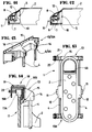
- such a fixing support 13, 13A comprises means 14 for receiving these ends 6, 6A of the slides 4, of tubular shape, as well as a fixing base 15.
- the latter is provided with openings 16 serving for the passage of fixing members, such as screws, when it is advisable to attach, directly, the hydrotherapy device 1 to any wall.
- this fixing base 15 can receive hooking means 18 and clamping means 20 allowing, ultimately, simply to hang the hydrotherapy device 1 on such a wall 17 of a cabin. shower.
- attachment means 18 are in the form of an inverted "U" piece 19 of which at least one of the vertical parallel walls 19A is made integral with the fixing base 15, while the other parallel wall vertical 19B receives the clamping means 20, such as a screw or the like. These are tightened on the upper section 17A of this wall 17 once the "U" piece 19 engaged on the latter.
- the fixing supports 13, 13A can be mounted or be an integral part of a single panel which can then receive, on one of its lateral edges such hinge fittings 22 authorizing the pivoting of the hydrotherapy device 1 around a vertical axis.
- this hydrotherapy device 1 is pivotable relative to the partition against which it is fixed may prove to be particularly advantageous in the context of an application of this device above a bathtub. More particularly, in this case, this hydrotherapy device 1 can, as the case may be, be folded down parallel to the partition against which it is fixed in order to make it less bulky or, on the contrary, in the event of use , brought perpendicular to this partition, for example in the longitudinal axis of the bathtub.
- these nozzles 3 are connected to a conduit 47 of a primary water supply network and deliver a water jet with a massaging effect.
- these nozzles 3 comprise means for transforming the flow of water from the primary network into an outlet pressure greater than that of the latter, when it is expelled into the open air.
- the means for transforming the flow of water into pressure are constituted by a first chamber A for reducing the cross-section of the primary water supply duct of the nozzle 3 and a pressure chamber C succeeding it, of larger section and extending itself, by an expulsion chamber D whose section of dimension smaller than the pressure chamber C constitutes a second reduction.
- the pressure chamber C comprises means for giving the water flow a swirling spiral movement, these means 23 being constituted, essentially, by a helical groove 24, which can preferably be likened to a thread whose pitch of the propeller is very large and advantageously comprising an asymmetrical profile.
- an injection chamber B of section smaller than that of the first reduction A is interposed between the latter and the pressure chamber C to constitute a third reduction.
- the injection chamber B has a diameter corresponding to the diameter of the chamber A divided by two. While the pressure chamber C has a diameter corresponding to twice the diameter of the first chamber A, that is four times greater than the diameter of the injection chamber B. Finally, the expulsion chamber D has a diameter , corresponding, substantially, to that of the first intake chamber A.
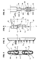
- FIG. 5 In order to better understand the phenomenon applied in the context of the present invention, reference will be made, more particularly, to FIG. 5.
- this is divided into a rotating mass a and an accelerating mass b.
- the rotation of part of the flow generates a vacuum in the center of the pressure chamber C which allows the part of the flow b to evolve freely and to accelerate.
- air injection means operating, for example, by a venturi effect.
- a nozzle 3 consists of a tubular rear body 24 determining the different chambers A, B, C for transforming the flow of water into outlet pressure and a front part 25 intended to ensure the 'emission of at least one jet of pressurized water and constituting, substantially, the expulsion chamber D.
- the pressure chamber C of the nozzle 3 and the injection chamber B are arranged on the same axis X, X 'while the first intake chamber A is located on another axis Y, Y 'perpendicular to the first.
- this rear body 24 of the nozzle 3 comprises, at its front end and on its outer periphery, a recess 26 defining a nozzle 27 of smaller section intended to be inserted in an orifice 28 formed in the hull support 2.
- This endpiece 27 is, moreover, threaded on its outer periphery for the reception of a lock nut 29 allowing, ultimately, to fix the nozzle 3 on this support shell 2.
- the front part 25 of said nozzle 3 is constituted, substantially, by a tubular insert 30 whose internal diameter is defined so as to constitute, substantially, said expulsion chamber D.
- this insert 30 comprises a front flange 31 provided with at least one central perforation 32 intended for the passage of a jet of pressurized water.
- the front flange 31 of this insert 30 comprises, a central perforation 32 and one or more peripheral perforations 33. More particularly the central perforation 32, preferably of a larger diameter has for purpose of allowing the expulsion of the accelerated water flow b, while the peripheral perforations 33 allow the ejection of the rotating body of water a.
- this front part 25 of a nozzle 3 can receive an adjustment cap 34 capable of being screwed onto the threaded end piece 27 of the rear body 24 and offering the possibility of adjust the water jet (s) at the nozzle outlet.
- this adjustment cap 34 has, on its front face, perforations 35, 36 including a central 35 capable of being positioned in line with the central perforation 32 of the insert 30. Consequently, by screwing in fully, the adjustment cap 34 so that it comes into contact against the front flange 31 of the insert 30 while ensuring the offset of the peripheral perforations 32 of the latter relative to those 36 of said adjustment cap 34, one obtains a single central jet. Then by unscrewing, gradually, this adjustment cap 34, one obtains as many jets as perforations 35, 36 knowing that the more one moves away from the front flange 31, the more the jets are flared.
- the nozzle 3 corresponding to the embodiment illustrated in FIG. 8 differs, essentially, from that described above in that the rear body 24 consists of two parts 24A, 24B.
- the first defines, in a way, the pressure chamber C and is in the form of a socket screwed into the part 24B and comprising at its internal wall, the thread defining the means 23 to give the water flow a swirling spiral movement.
- this part 24A in the form of a socket comprises, also at the periphery, an annular flange 37 playing, in a way, the role of the lock nut 29 in the embodiment corresponding to FIG. 6.
- the part 24A in the form of a socket, is introduced into the orifice 28 formed in said support shell 2, then it is screwed into the part 24B of said rear body 24 until they are tightened on the wall of said support shell 2.
- the insert 30A which receives the front end of the rear body 24 is, in this case, in the form of a flange having, substantially distributed around its center 38, perforations 39, 39A of different diameter or perforation groups 39B to the right of which an opening 40 can be positioned arranged in an adjustment cap 34A pivotally mounted on the front part 25 of the nozzle 3.
- this adjustment cap 34A pivotally mounted on the front part 25 of the nozzle 3.
- the nozzles 3 are arranged on a secondary water supply network 41 according to a distribution such as to obtain a regulation of the flows as a function of the desired conditions and massage points of the body.
- the supply network 41 consists of two groups 42, 43 of nozzles in parallel 3.1 to 3.6 relative to a common supply point 44.
- Each of the groups 42, 43 being itself formed three nozzles 3.1 to 3.3 and 3.4 to 3.6 connected together, in series.
- the secondary water supply network 41 can constitute, in itself, the first reduction chamber A, this with respect to the primary supply network 47.
- connection of this secondary supply network 41 to the primary network 47 is obtained using flexible connection means.
- the secondary supply network 41 of the latter is connected by means of a hose to the shower outlet of the existing shower tap. .
- this avoids any delicate execution of plumbing.
- the nozzles or groups of nozzles 3 are connected to water supply means acting successively and / or gradually in a direction going from the bottom to the top for the massage zones located below the hips. and from top to bottom for areas above the hips to achieve a drainage effect.
- These drainage means are constituted, for example, by a multi-way valve driven in rotation, either by pressure hydraulic produced by the primary supply water flow 44, or by an appropriate electric motor.
- a nozzle 3 can be provided rotating and driven in rotation by hydraulic pressure this in order to produce a penetrating local massage.
- the hydrotherapy device in accordance with the invention while being remarkably effective, turns out to be easy to use and, more particularly, to be easily assembled so that one can envisage its installation in any type of shower cubicle or even above any bathtub.
Landscapes
- Health & Medical Sciences (AREA)
- Epidemiology (AREA)
- Pain & Pain Management (AREA)
- Physical Education & Sports Medicine (AREA)
- Rehabilitation Therapy (AREA)
- Life Sciences & Earth Sciences (AREA)
- Animal Behavior & Ethology (AREA)
- General Health & Medical Sciences (AREA)
- Public Health (AREA)
- Veterinary Medicine (AREA)
- Massaging Devices (AREA)
- Bathtubs, Showers, And Their Attachments (AREA)
Abstract
Description
La présente invention concerne un dispositif d'hydrothérapie destiné au massage du corps humain.The present invention relates to a hydrotherapy device for massaging the human body.
Il est fait de plus en plus appel à ce genre de thérapies afin d'effectuer par l'intermédiaire de jets d'eau, plus ou moins puissants, le massage recherché.This type of therapy is used more and more in order to carry out the desired massage by means of water jets, more or less powerful.
Il est connu d'appliquer de telles thérapies à différentes zones du corps humain comme par exemple pour soigner le mal de dos pouvant provenir de différents facteurs que l'on peut retrouver de manière pathologique, chronique, ou passagère.It is known to apply such therapies to different areas of the human body such as for example to treat back pain which can come from different factors which can be found in a pathological, chronic, or transient manner.
Les attitudes comportementales de la vie moderne contribuent également à ce type de mal. Il s'agira de la position assise prolongée devant un poste de travail ou lors de la conduite d'un véhicule, des efforts de levage, les vibrations etc...The behavioral attitudes of modern life also contribute to this type of evil. It will be a prolonged sitting position in front of a work station or when driving a vehicle, lifting efforts, vibrations, etc.
Entrent également en ligne de compte, les facteurs de stress et neurologiques qui suscitent parfois un massage en vue d'une relaxation.Also taken into account are the stress and neurological factors that sometimes trigger a massage for relaxation.
On peut aussi avoir recours au massage dans le cas d'une musculature déficiente afin de stimuler certaines masses molles.Massage can also be used in the case of deficient muscles in order to stimulate certain soft masses.
D'autres situations peuvent aussi inciter au massage comme la mauvaise circulation sanguine, les rhumatismes etc...Other situations can also encourage massage such as poor blood circulation, rheumatism etc ...
Dans tous les cas de figure le massage peut être effectué à titre préventif en usage privé ou en complément d'un traitement médical.In all cases, the massage can be carried out as a preventive measure for private use or in addition to medical treatment.
Les dispositifs généralement connus pour obtenir ces massages par hydrothérapie sont constitués, dans les installations domestiques, par des douchettes à jets réglables, mais leur efficacité est réduite car la force d'expulsion de l'eau est limitée à la valeur nominale de la pression du réseau primaire d'alimentation. Or l'effort hydromassant n'est obtenu qu'au-delà de cette valeur.The devices generally known for obtaining these massages by hydrotherapy consist, in domestic installations, of hand showers with adjustable jets, but their effectiveness is reduced because the force of expulsion of the water is limited to the nominal value of the pressure of the primary supply network. However, the hydromassage effort is only obtained beyond this value.
A ce propos, il est connu par le document FR-A-2.452.919 un appareil d'hydrothérapie, en particulier pour le traitement des algies vertébrales, composé d'un cadre tubulaire équipé de buses de pulvérisation d'eau en provenance d'un réseau d'alimentation eau chaude - eau froide. Malgré son ajustement en hauteur possible cet appareil est très limité, quant aux possibilités de massage qu'il est en mesure d'offrir, sans compter que son efficacité reste, là encore, très réduite en raison d'une pression d'eau insuffisante procurée par des buses, on ne peut plus classiques.In this regard, it is known from document FR-A-2,452,919 a hydrotherapy device, in particular for the treatment of vertebral pain, composed of a tubular frame equipped with nozzles for spraying water from a hot water - cold water supply network. Despite its possible height adjustment, this device is very limited, in terms of the massage possibilities it is able to offer, not to mention that its effectiveness remains, here again, very reduced due to insufficient water pressure provided. by nozzles could not be more conventional.
C'est ainsi que dans les installations médicales ou paramédicales professionnelles on obtient des pressions fortes en ayant recours à des compresseurs auxiliaires.This is how, in professional medical or paramedical installations, strong pressures are obtained by using auxiliary compressors.
Tout particulièrement, il est connu par le document WO-A-87.07499 une machine d'hydromassage à même d'équiper une cabine de douche et comportant une structure tubulaire en forme d'une cage dont notamment les montants sont équipés de pommes de douchettes. Cette structure tubulaire est alimentée en eau sous pression par l'intermédiaire d'une pompe.In particular, it is known from document WO-A-87.07499 a hydromassage machine capable of equipping a shower cabin and comprising a tubular structure in the form of a cage, in particular the uprights are equipped with shower heads. This tubular structure is supplied with pressurized water via a pump.
Ce type d'installation est bien entendu fort coûteux et de plus d'usage limité.This type of installation is of course very expensive and moreover of limited use.
En effet, on imagine mal un particulier investir dans ce type de matériel tant du point de vue du coût que de l'encombrement qu'il représente.Indeed, it is hard to imagine an individual investing in this type of equipment both from the point of view of cost and the size it represents.
C'est ainsi que selon une première phase de la démarche inventive il a été imaginé de proposer à une clientèle professionnelle, mais également privée, de transformer une cabine de douche existante ou une baignoire traditionnelle par l'intermédiaire d'un dispositif d'hydrothérapie facilement adaptable se présentant sous la forme d'un module prééquipé apte à être mis en place sur une paroi de ladite cabine ou contre le mur par des moyens de fixation appropriés et sans aucune intervention de plomberie ou d'électricité.Thus, according to a first phase of the inventive step it was imagined to offer to a professional clientele, but also private, to transform an existing shower cubicle or a traditional bathtub via a hydrotherapy device easily adaptable in the form of a pre-equipped module capable of being placed on a wall of said cabin or against the wall by suitable fixing means and without any intervention of plumbing or electricity.
En fait, il a été recherché de concevoir un dispositif à monter éventuellement soi-même, notamment dans le cadre d'un usage privé, mais ayant des caractéristiques répondant aux critères de l'hydromassage, plus particulièrement en ce qui concerne la valeur de la pression de sortie des jets d'eau et cela sans aucun matériel annexe tel que compresseur.In fact, it has been sought to design a device that can be fitted yourself, in particular for private use, but having characteristics that meet the criteria of hydromassage, more particularly as regards the value of the outlet pressure of the water jets, without any additional equipment such as a compressor.
Les objectifs sont atteints par la mise en oeuvre des moyens qui seront décrits plus loin et qui constituent l'invention proprement dite.The objectives are achieved by the implementation of the means which will be described later and which constitute the invention itself.
A cet effet, l'invention concerne un dispositif d'hydrothérapie destiné au massage du corps humain et comportant au moins une buse raccordée à un conduit d'un réseau primaire d'alimentation en eau et délivrant un jet d'eau à effet massant, ce dispositif comportant des moyens propres de transformation du débit d'eau de ce réseau primaire en pression de sortie supérieure à celle dudit réseau à son expulsion à l'air libre, caractérisé par le fait que lesdits moyens de transformation du débit d'eau en pression sont constitués, en combinaison, par une première chambre de réduction de la section du conduit primaire d'alimentation en eau suivie d'une chambre de pression de section plus importante et comportant des moyens pour conférer au flux d'eau un mouvement tourbillonnaire en spirale, dans le prolongement axial de cette chambre de pression se situant une chambre d'expulsion dont la section, de dimension inférieure à la chambre de pression, constitue une nouvelle réduction.To this end, the invention relates to a hydrotherapy device intended for massaging the human body and comprising at least one nozzle connected to a conduit of a primary water supply network and delivering a jet of water with a massaging effect, this device comprising its own means for transforming the flow of water from this primary network into an outlet pressure greater than that of said network when it is expelled into the open air, characterized in that said means for transforming the flow of water into pressure consist, in combination, of a first reduction chamber of the section of the primary duct water supply followed by a pressure chamber of larger section and comprising means for imparting to the water flow a swirling spiral movement, in the axial extension of this pressure chamber being located an expulsion chamber whose the section, which is smaller than the pressure chamber, constitutes a further reduction.
En outre, selon l'invention, la ou les buses sont raccordées à un réseau d'adduction secondaire d'alimentation en eau équipant une coque support et comportant des moyens de raccordement flexibles au réseau primaire, ladite coque support étant montée coulissante sur des glissières latérales et comportant des moyens de blocage en translation déverrouillables.In addition, according to the invention, the nozzle (s) are connected to a secondary water supply network fitted to a support shell and comprising flexible connection means to the primary network, said support shell being slidably mounted on slides. lateral and comprising unlockable translation locking means.
Avantageusement, les extrémités supérieures, respectivement inférieures des glissières latérales sont rendues solidaires de supports de fixation pourvus de ferrures d'articulation, autorisant le montage pivotant de cette coque sur une paroi.Advantageously, the upper and lower ends respectively of the lateral slides are made integral with fixing supports provided with articulation fittings, allowing the pivoting mounting of this shell on a wall.
Les avantages découlant de la présente invention sont particulièrement marquants. En effet, les caractéristiques spécifiques des buses permettent d'obtenir, au travers de ces dernières, des jets d'eau produisant un réel effet massant, ceci en partant d'une pression correspondant à celle du réseau d'alimentation en eau et sans faire appel à un quelconque surpresseur.The advantages resulting from the present invention are particularly striking. Indeed, the specific characteristics of the nozzles make it possible to obtain, through the latter, water jets producing a real massaging effect, this starting from a pressure corresponding to that of the water supply network and without making call to any booster.
En outre, le montage coulissant de la coque sur des glissières latérales et le raccordement de son réseau d'adduction secondaire à l'aide d'un flexible au réseau primaire d'alimentation en eau permettant de la déplacer aisément de manière à ajuster sa position par rapport aux parties du corps sur lesquelles l'on souhaite agir et, ceci sans limite de la tête aux pieds.In addition, the sliding mounting of the hull on side rails and the connection of its secondary supply network using a hose to the primary water supply network allows it to be easily moved so as to adjust its position compared to the parts of the body on which one wishes to act and, this without limit from head to toe.
La possibilité d'un montage pivotant de l'ensemble sur une paroi facilite, en outre, son orientation. En fait, un tel montage est tout particulièrement avantageux dans le cas d'une application du dispositif au-dessus d'une baignoire. Tout particulièrement, dans ces conditions, le dispositif peut être, soit rabattu contre le mur contre lequel est implantée la baignoire, soit orienté dans l'axe longitudinal de cette dernière.The possibility of pivoting mounting of the assembly on a wall also facilitates its orientation. In fact, such an arrangement is very particularly advantageous in the case of an application of the device above a bathtub. In particular, under these conditions, the device can be either folded against the wall against which the bathtub is located, or oriented in the longitudinal axis of the latter.
En fin de compte, le dispositif selon l'invention apporte une réelle solution aux besoins de tout un chacun, grâce à son efficacité et son coût de revient réduit.In the end, the device according to the invention provides a real solution to the needs of everyone, thanks to its efficiency and its reduced cost price.
La présente invention concerne, également, les caractéristiques qui ressortiront de la description qui va suivre et qui devront être considérées isolément ou selon toutes leurs combinaisons techniques possibles.The present invention also relates to the characteristics which will emerge from the description which follows and which should be considered in isolation or according to all their possible technical combinations.
Cette description, donnée à titre d'exemple non limitatif, fera mieux comprendre comment l'invention peut être réalisée en référence aux dessins annexés sur lesquels :
- la figure 1 est une vue schématisée et en plan d'un dispositif d'hydrothérapie selon l'invention, la coque étant illustrée dans ses deux positions extrêmes sur les glissières latérales le long desquelles elle est à même de se déplacer ;
- la figure 2 est une vue latérale du dispositif d'hydrothérapie tel que représenté dans la figure 1, les glissières latérales n'étant pas représentées ;
- la figure 3 est une vue schématique d'un réseau d'adduction d'eau secondaire selon un exemple de réalisation ;
- la figure 4 est une vue du principe général sur lequel est basée l'invention ;
- la figure 5, correspondant à une vue schématisée, en perspective et en coupe partielle de la buse, illustre schématiquement, le principe mis en oeuvre grâce aux caractéristiques spécifiques de la chambre de pression ;
- la figure 6 est une vue schématisée et en coupe longitudinale de la buse ;
- la figure 7 est une vue frontale de l'insert situé à l'avant de la buse telle que représentée dans la figure 6 ;
- la figure 8 est une vue schématisée et en coupe longitudinale de la buse exécutée selon un second mode de réalisation ;
- la figure 9 est une vue de la face frontale de cette buse telle que représentée dans la figure 7 ;
- la figure 10 est une vue schématisée et en plan d'un insert rotatif disposé à l'arrière de cette face frontale permettant de varier la nature du jet ;
- les figures 11 et 12 illustrent, de manière schématisée et en coupe, les moyens de blocage en translation de la coque sur les glissières latérales, ces moyens étant représentés en position de blocage et de déblocage ;
- la figure 13 est une vue schématisée et en perspective d'un support de fixation dont sont rendues solidaires, selon le cas, les extrémités supérieures ou inférieures des glissières latérales ;
- la figure 14 est une vue schématisée et en élévation des moyens d'accrochage et de serrage à même d'équiper notamment le support de fixation supérieur dudit dispositif permettant l'accrochage de ce dernier sur une paroi, par exemple, d'une cabine de douche ;
- la figure 15 est une vue schématisée et en élévation du dispositif dont les supports de fixation sont pourvus de moyens d'articulation permettant le montage pivotant de ce dispositif contre une paroi.
- Figure 1 is a schematic plan view of a hydrotherapy device according to the invention, the shell being illustrated in its two extreme positions on the side rails along which it is able to move;
- Figure 2 is a side view of the hydrotherapy device as shown in Figure 1, the side rails are not shown;
- Figure 3 is a schematic view of a secondary water supply network according to an exemplary embodiment;
- Figure 4 is a view of the general principle on which the invention is based;
- FIG. 5, corresponding to a diagrammatic view, in perspective and in partial section of the nozzle, illustrates diagrammatically, the principle implemented by virtue of the specific characteristics of the pressure chamber;
- Figure 6 is a schematic view in longitudinal section of the nozzle;
- Figure 7 is a front view of the insert located at the front of the nozzle as shown in Figure 6;
- Figure 8 is a schematic view in longitudinal section of the nozzle executed according to a second embodiment;
- Figure 9 is a view of the front face of this nozzle as shown in Figure 7;
- Figure 10 is a schematic plan view of a rotary insert disposed at the rear of this front face for varying the nature of the jet;
- Figures 11 and 12 illustrate, schematically and in section, the means for locking in translation of the shell on the side rails, these means being shown in the locking and unlocking position;
- Figure 13 is a schematic perspective view of a fixing support which are made integral, as appropriate, the upper or lower ends of the side rails;
- FIG. 14 is a diagrammatic view in elevation of the hooking and tightening means capable of fitting in particular the upper fixing support of said device allowing the latter to be hooked on a wall, for example, of a cabin shower;
- FIG. 15 is a diagrammatic view in elevation of the device, the fixing supports of which are provided with articulation means allowing the pivoting mounting of this device against a wall.
Le dispositif d'hydrothérapie 1 globalement désigné sur les figures 1, 2 et 15, comprend un panneau support ou coque 2 moulé en matière plastique préférentiellement en polychlorure de vinyle, sur lequel sont disposées une ou plusieurs buses 3 destinées au traitement hydrothérapique par l'émission de jets d'eau contrôlés. Selon l'exemple représenté, les buses 3 sont au nombre de six, leurs dispositions particulières étant commentées plus loin.The hydrotherapy device 1, generally designated in FIGS. 1, 2 and 15, comprises a support panel or
Comme le montre, également, la figure 1, la coque support 2 est montée coulissante sur des glissières latérales 4 et comporte, par ailleurs, des moyens de blocage en translation déverrouillables 5, plus particulièrement illustrés dans les figures 11 et 12, ayant pour fonction d'immobiliser ladite coque support 2 sur lesdites glissières 4 tout en autorisant, sous l'action d'une commande manuelle, son déplacement le long de ces dernières.As also shown in FIG. 1, the
En fin de compte, grâce à cette configuration la coque 2 du dispositif d'hydrothérapie peut, tel que représenté dans la figure 1, être disposée à n'importe quel endroit le long de ces glissières latérales 4 de manière à permettre à l'usager d'assurer le massage d'une partie quelconque du corps.Ultimately, thanks to this configuration, the
Pour en revenir aux moyens de blocage déverrouillables 5, ceux-ci consistent, de part et d'autre de la coque support 2, en une mâchoire mobile 7 et une mâchoire fixe 8 emprisonnant une glissière 4, notamment de forme tubulaire. La mâchoire mobile 7 est montée pivotante autour d'un axe 9 sensiblement parallèle à ladite glissière, tandis que des moyens élastiques 10 assurent son rappel en position de blocage, resserrée sur ladite glissière 4. A noter que cette mâchoire mobile 7 est prolongée, au-delà de l'axe 9, par une poignée de manoeuvre 11 aisément accessible par l'usager sur les côtés de la coque support 2 en vue d'assurer le blocage et le déblocage en translation de cette dernière. En outre, au niveau de ses parties latérales, cette coque support 2 comporte, au droit desdites poignées de manoeuvre 11, des rebords d'appui 12 permettant à l'usager de saisir simultanément lesdites poignées de manoeuvre 11 et la coque support 2 en vue d'ajuster sa position le long des glissières 4.To return to the unlockable locking means 5, these consist, on either side of the
Celles-ci peuvent être équipées, à leur extrémité inférieure 6 et supérieure 6A, de moyens de fixation individuels permettant de les rapporter, indépendamment contre une paroi. Toutefois, en vue de faciliter le montage du dispositif d'hydrothérapie 1 et, par ailleurs, garantir le parallélisme de ces glissières latérales 4, celles-ci sont solidaires, à leur extrémité inférieure 6, respectivement, supérieure 6A, de supports de fixation 13, 13A.These can be fitted, at their lower 6 and upper 6A ends, with individual fixing means allowing them to be attached independently to a wall. However, in order to facilitate the mounting of the hydrotherapy device 1 and, moreover, to guarantee the parallelism of these lateral slides 4, these are integral, at their
Tel que représenté plus particulièrement en figure 13, un tel support de fixation 13, 13A comporte des moyens de réception 14 de ces extrémités 6, 6A des glissières 4, de forme tubulaire, ainsi qu'une embase de fixation 15. A ce propos, celle-ci est pourvue d'ouvertures 16 servant au passage d'organes de fixation, tels que vis, lorsqu'il convient de rapporter, directement, le dispositif d'hydrothérapie 1 sur une paroi quelconque.As shown more particularly in FIG. 13, such a
Toutefois, lorsque l'on souhaite équiper sa douche d'un tel dispositif d'hydrothérapie 1, il peut s'avérer utile de pouvoir l'appliquer directement sur la paroi 17 d'une cabine de douche, telle que représentée dans la figure 14. Or, celle-ci est souvent constituée par un panneau, soit en verre soit en plexiglas translucide, qui ne permet pas la pose au moyen de vis. Dans de telles conditions, cette embase de fixation 15 peut recevoir des moyens d'accrochage 18 et des moyens de serrage 20 permettant, finalement, d'accrocher, simplement, le dispositif d'hydrothérapie 1 sur une telle paroi 17 d'une cabine de douche.However, when it is desired to equip the shower with such a hydrotherapy device 1, it may prove useful to be able to apply it directly to the
Finalement, de tels moyens d'accrochage 18 se présentent sous forme d'une pièce en « U » renversé 19 dont au moins une des parois parallèles verticales 19A est rendue solidaire de l'embase de fixation 15, tandis que l'autre paroi parallèle verticale 19B reçoit les moyens de serrage 20, tels qu'une vis ou analogue. Ceux-ci sont resserrés sur le profilé supérieur 17A de cette paroi 17 une fois la pièce en « U » 19 engagée sur cette dernière.Finally, such attachment means 18 are in the form of an inverted "U"
Tel que visible en figure 15, on peut, encore équiper les supports de fixation 13, 13A, à l'une de leurs extrémités latérales 21, d'une ferrure d'articulation 22 sous forme, par exemple, d'une paumelle, dont la lame fixe est rendue solidaire, à l'aide d'organes de fixation appropriés, d'une paroi quelconque. A noter que, selon une variante de réalisation, les supports de fixation 13, 13A peuvent être montés ou faire partie intégrante d'un seul et même panneau lequel peut alors recevoir, sur l'un de ses bords latéraux de telles ferrures d'articulation 22 autorisant le pivotement du dispositif d'hydrothérapie 1 autour d'un axe vertical.As shown in FIG. 15, it is also possible to equip the fixing supports 13, 13A, at one of their lateral ends 21, with a hinge fitting 22 in the form, for example, of a hinge, of which the fixed blade is made integral, by means of appropriate fixing members, with any wall. Note that, according to an alternative embodiment, the fixing supports 13, 13A can be mounted or be an integral part of a single panel which can then receive, on one of its lateral edges
En fin de compte, le fait que ce dispositif d'hydrothérapie 1 soit pivotant par rapport à la cloison contre laquelle il est fixé peut s'avérer particulièrement avantageux dans le cadre d'une application de ce dispositif au-dessus d'une baignoire. Plus particulièrement, dans ce cas d'espèce, ce dispositif d'hydrothérapie 1 peut, selon le cas, être rabattu parallèlement à la cloison contre laquelle il est fixé en vue de le rendre moins encombrant ou, au contraire, en cas d'utilisation, ramené perpendiculairement à cette cloison, par exemple dans l'axe longitudinal de la baignoire.In the end, the fact that this hydrotherapy device 1 is pivotable relative to the partition against which it is fixed may prove to be particularly advantageous in the context of an application of this device above a bathtub. More particularly, in this case, this hydrotherapy device 1 can, as the case may be, be folded down parallel to the partition against which it is fixed in order to make it less bulky or, on the contrary, in the event of use , brought perpendicular to this partition, for example in the longitudinal axis of the bathtub.
Pour en revenir aux buses 3, celles-ci sont raccordées à un conduit 47 d'un réseau primaire d'alimentation en eau et délivrent un jet d'eau à effet massant. En fait, ces buses 3 comportent des moyens de transformation du débit d'eau du réseau primaire en pression de sortie supérieure à celle de ce dernier, à son expulsion à l'air libre.To return to the
Selon le schéma de principe de la figure 4, les moyens de transformation du débit d'eau en pression sont constitués par une première chambre A de réduction de la section du conduit primaire d'alimentation en eau de la buse 3 et une chambre de pression C lui succédant, de section plus importante et se prolongeant, elle-même, par une chambre d'expulsion D dont la section de dimension inférieure à la chambre de pression C constitue une seconde réduction.According to the block diagram of FIG. 4, the means for transforming the flow of water into pressure are constituted by a first chamber A for reducing the cross-section of the primary water supply duct of the
En outre, selon l'invention, la chambre de pression C comporte des moyens pour conférer au flux d'eau un mouvement tourbillonnaire en spirale, ces moyens 23 étant constitués, substantiellement, par une rainure hélicoïdale 24, assimilable préférentiellement à un filet dont le pas de l'hélice est très grand et comportant, avantageusement un profil dissymétrique.In addition, according to the invention, the pressure chamber C comprises means for giving the water flow a swirling spiral movement, these means 23 being constituted, essentially, by a
Avantageusement, une chambre d'injection B de section inférieure à celle de la première réduction A est interposée entre cette dernière et la chambre de pression C pour constituer une troisième réduction.Advantageously, an injection chamber B of section smaller than that of the first reduction A is interposed between the latter and the pressure chamber C to constitute a third reduction.
Selon un mode de réalisation préférentiel, si l'on définit la première chambre A comme une chambre d'admission, la chambre d'injection B comporte un diamètre correspondant au diamètre de la chambre A divisé par deux. Tandis que la chambre de pression C comporte, elle, un diamètre correspondant à deux fois le diamètre de la première chambre A, soit quatre fois supérieur au diamètre de la chambre d'injection B. Finalement, la chambre d'expulsion D comporte un diamètre, correspondant, sensiblement, à celui de la première chambre d'admission A.According to a preferred embodiment, if the first chamber A is defined as an intake chamber, the injection chamber B has a diameter corresponding to the diameter of the chamber A divided by two. While the pressure chamber C has a diameter corresponding to twice the diameter of the first chamber A, that is four times greater than the diameter of the injection chamber B. Finally, the expulsion chamber D has a diameter , corresponding, substantially, to that of the first intake chamber A.
De manière à mieux comprendre le phénomène mis en application dans le cadre de la présente invention, l'on se reportera, plus particulièrement, à la figure 5. Ainsi, l'on observe que sous l'effet de la mise en mouvement tourbillonnaire en spirale du flux d'eau celui-ci est divisé en une masse en rotation a et une masse en accélération b. Plus particulièrement, la mise en rotation d'une partie du flux génère une dépression au centre de la chambre de pression C qui permet à la partie du flux b d'évoluer librement et de s'accélérer. L'on peut, évidemment, prévoir au niveau de cette buse 3, des moyens d'injection d'air fonctionnant, par exemple, par effet venturi.In order to better understand the phenomenon applied in the context of the present invention, reference will be made, more particularly, to FIG. 5. Thus, it is observed that under the effect of the vortex movement in spiral of the water flow, this is divided into a rotating mass a and an accelerating mass b. More particularly, the rotation of part of the flow generates a vacuum in the center of the pressure chamber C which allows the part of the flow b to evolve freely and to accelerate. It is obviously possible to provide, at the level of this
Comme le montrent les figures 6 et 8, une buse 3 est constituée d'un corps arrière tubulaire 24 déterminant les différentes chambres A, B, C de transformation du débit d'eau en pression de sortie et une partie avant 25 destinée à assurer l'émission d'au moins un jet d'eau sous pression et constituant, substantiellement, la chambre d'expulsion D.As shown in FIGS. 6 and 8, a
Selon ces exemples de réalisation, la chambre de pression C de la buse 3 et la chambre d'injection B sont disposées sur un même axe X, X' alors que la première chambre d'admission A se situe sur un autre axe Y, Y' perpendiculaire au premier.According to these exemplary embodiments, the pressure chamber C of the
Quoi qu'il en soit, ce corps arrière 24 de la buse 3 comporte, à son extrémité avant et sur son pourtour externe, un décrochement 26 définissant un embout 27 de section plus réduite destiné à être inséré dans un orifice 28 ménagé dans la coque support 2. Cet embout 27 est, par ailleurs, fileté sur son pourtour externe pour la réception d'un contre écrou 29 permettant, en définitive, de fixer la buse 3 sur cette coque support 2.Anyway, this
Quant à la partie avant 25 de ladite buse 3, elle est constituée, substantiellement, par un insert tubulaire 30 dont le diamètre interne est défini de manière à constituer, substantiellement, ladite chambre d'expulsion D.As for the
Tel que visible dans la figure 7, cet insert 30 comporte un flasque avant 31 pourvu d'au moins une perforation centrale 32 destinée au passage d'un jet d'eau sous pression.As visible in FIG. 7, this
En fin de compte, selon un mode de réalisation préférentiel, le flasque avant 31 de cet insert 30 comporte, une perforation centrale 32 et une ou plusieurs perforations périphériques 33. Plus particulièrement la perforation centrale 32, préférentiellement d'un diamètre plus important a pour but de permettre l'expulsion du flux d'eau accéléré b, tandis que les perforations périphériques 33 permettent l'éjection de la masse d'eau en rotation a.Ultimately, according to a preferred embodiment, the
Finalement, cette partie avant 25 d'une buse 3 peut recevoir une calotte de réglage 34 à même d'être vissée sur l'embout filetée 27 du corps arrière 24 et offrant la possibilité de régler le ou les jets d'eau en sortie de buse. Plus particulièrement, cette calotte de réglage 34 comporte, sur sa face avant, des perforations 35, 36 dont une 35 centrale susceptible de se positionner au droit de la perforation centrale 32 de l'insert 30. En conséquence, en vissant à fond, la calotte de réglage 34 de telle sorte qu'elle vienne en applique contre le flasque avant 31 de l'insert 30 tout en assurant le décalage des perforations périphériques 32 de ce dernier par rapport à celles 36 de ladite calotte de réglage 34, l'on obtient un jet central unique. Puis en dévissant, progressivement, cette calotte de réglage 34, l'on obtient autant de jets que de perforations 35, 36 sachant que plus on s'éloigne du flasque avant 31, plus les jets sont évasés.Finally, this
Il est également possible de prévoir qu'en dévissant la calotte de réglage 34, il en résulte une injection d'air, par effet venturi, dans la buse 3, tout particulièrement au niveau de la chambre d'expulsion D.It is also possible to provide that by unscrewing the
La buse 3 correspondant au mode de réalisation illustré dans la figure 8 se distingue, essentiellement, de celle décrite précédemment en ce que le corps arrière 24 est constitué de deux pièces 24A, 24B. La première définit, en quelque sorte, la chambre de pression C et se présente sous forme d'une douille vissée dans la pièce 24B et comportant au niveau de sa paroi interne, le filetage définissant les moyens 23 pour conférer au flux d'eau un mouvement tourbillonnaire en spirale. En fin de compte, cette partie 24A en forme de douille comporte, également en périphérie, un rebord annulaire 37 jouant, en quelque sorte, le rôle du contre écrou 29 dans le mode de réalisation correspondant à la figure 6. Plus précisément, lors du montage de la buse 3 sur la coque support 2, l'on introduit la partie 24A, en forme de douille, dans l'orifice 28 ménagé dans ladite coque support 2, puis on vient la visser dans la partie 24B dudit corps arrière 24 jusqu'à obtenir leur resserrement sur la paroi de ladite coque support 2.The
De plus, l'insert 30A que reçoit l'extrémité avant du corps arrière 24 se présente, dans ce cas, sous forme d'un flasque comportant, sensiblement réparti autour de son centre 38, des perforations 39, 39A de diamètre différent ou des groupes de perforation 39B au droit desquels l'on peut positionner une ouverture 40 aménagée dans une calotte de réglage 34A montée pivotante sur la partie avant 25 de la buse 3. En fin de compte, en agissant sur cette calotte de réglage 34A, on peut, là encore, obtenir des jets de forme et de pression différentes.In addition, the
Comme illustré dans la figure 3, les buses 3 sont disposées sur un réseau d'adduction secondaire 41 d'alimentation en eau selon une répartition telle à obtenir une régulation des flux en fonction des conditions et points de massage du corps souhaités.As illustrated in FIG. 3, the
Ainsi, selon l'exemple illustré le réseau d'adduction 41 est constitué de deux groupes 42, 43 de buses en parallèle 3.1 à 3.6 par rapport à un point d'alimentation commun 44. Chacun des groupes 42, 43 étant lui-même formé de trois buses 3.1 à 3.3 et 3.4 à 3.6 raccordées entre elles, en série.Thus, according to the example illustrated, the supply network 41 consists of two
On notera la présence d'un raccord 45 branché en parallèle sur le point d'alimentation commun 44 et destiné à une douchette (non représentée).Note the presence of a
On peut, naturellement prévoir une vanne multivoies permettant de sélectionner le ou les groupes de buses alimentés en eau ou encore pour orienter l'eau en direction d'une douchette. Il est ainsi obtenu un dispositif disposant de six jets et d'une douchette.It is, of course, possible to provide a multi-way valve making it possible to select the group or groups of nozzles supplied with water or else to direct the water towards a spray. A device is thus obtained which has six jets and a hand shower.
Bien entendu, bien d'autres combinaisons sont possibles. Tout particulièrement, au travers de la vanne multivoies l'on peut encore envisager la possibilité de sélectionner une sortie en direction d'une fente de sortie d'eau horizontale 46 placée dans la partie supérieure de la coque support 2 destinée à produire un jet en forme de cascade.Of course, many other combinations are possible. In particular, through the multi-way valve, it is also possible to envisage the possibility of selecting an outlet in the direction of a horizontal
Quoi qu'il en soit, l'on observera que le réseau d'adduction secondaire d'eau 41 peut constituer, en soi, la première chambre de réduction A, ceci par rapport au réseau d'alimentation primaire 47.In any event, it will be observed that the secondary water supply network 41 can constitute, in itself, the first reduction chamber A, this with respect to the primary supply network 47.
En outre, selon l'invention, le raccordement de ce réseau d'adduction secondaire 41 au réseau primaire 47 est obtenu à l'aide de moyens de raccordement flexibles.In addition, according to the invention, the connection of this secondary supply network 41 to the primary network 47 is obtained using flexible connection means.
Concrètement, lors d'un usage domestique du dispositif d'hydrothérapie 1 conforme à l'invention, l'on vient raccorder le réseau d'adduction secondaire 41 de ce dernier au moyen d'un flexible à la sortie douchette du robinet de douche existant. On constate, là encore, que l'on évite, par ce biais, toute plomberie d'exécution délicate.Concretely, during domestic use of the hydrotherapy device 1 according to the invention, the secondary supply network 41 of the latter is connected by means of a hose to the shower outlet of the existing shower tap. . Here again, we note that this avoids any delicate execution of plumbing.
Selon une autre caractéristique de l'invention les buses ou groupes de buses 3 sont reliés à des moyens d'alimentation en eau agissant successivement et/ou progressivement dans un sens allant du bas vers le haut pour les zones de massage situées en dessous des hanches et du haut vers le bas pour les zones situées au-dessus des hanches en vue d'obtenir un effet de drainage.According to another characteristic of the invention, the nozzles or groups of
Ces moyens de drainage sont constitués, par exemple, par une vanne multivoies entraînée en rotation, soit par la pression hydraulique produite par le flux d'eau d'alimentation primaire 44, soit par un moteur électrique approprié.These drainage means are constituted, for example, by a multi-way valve driven in rotation, either by pressure hydraulic produced by the primary supply water flow 44, or by an appropriate electric motor.
Selon une autre variante de réalisation illustrée en figure 2, une buse 3 peut être prévue tournante et entraînée en rotation par la pression hydraulique ceci afin de produire un massage local pénétrant.According to another alternative embodiment illustrated in FIG. 2, a
En définitive, on constate que le dispositif d'hydrothérapie, conforme à l'invention tout en étant d'une efficacité remarquable s'avère d'utilisation facile et, plus particulièrement, d'un montage aisé de sorte que l'on peut envisager son implantation dans tout type de cabine de douche ou encore au-dessus d'une baignoire quelconque.Ultimately, it can be seen that the hydrotherapy device, in accordance with the invention while being remarkably effective, turns out to be easy to use and, more particularly, to be easily assembled so that one can envisage its installation in any type of shower cubicle or even above any bathtub.
Claims (22)
Applications Claiming Priority (2)
| Application Number | Priority Date | Filing Date | Title |
|---|---|---|---|
| FR9506166 | 1995-05-19 | ||
| FR9506166A FR2734155B1 (en) | 1995-05-19 | 1995-05-19 | HYDROTHERAPY DEVICE ESPECIALLY ADAPTABLE TO A SHOWER ENCLOSURE |
Publications (2)
| Publication Number | Publication Date |
|---|---|
| EP0743056A2 true EP0743056A2 (en) | 1996-11-20 |
| EP0743056A3 EP0743056A3 (en) | 1997-06-04 |
Family
ID=9479317
Family Applications (1)
| Application Number | Title | Priority Date | Filing Date |
|---|---|---|---|
| EP96440045A Withdrawn EP0743056A3 (en) | 1995-05-19 | 1996-05-17 | Hydrotherapy device for massaging the human body |
Country Status (2)
| Country | Link |
|---|---|
| EP (1) | EP0743056A3 (en) |
| FR (1) | FR2734155B1 (en) |
Cited By (6)
| Publication number | Priority date | Publication date | Assignee | Title |
|---|---|---|---|---|
| FR2800633A1 (en) * | 1999-11-05 | 2001-05-11 | Aubert Alain | Mixer for adding soluble or dispersible substance, e.g. to water or vapor used for massage, has tubular feeder with inlet and outlet chambers |
| FR2846551A1 (en) | 2002-10-31 | 2004-05-07 | E S M P | Hydrotherapy unit for body massage comprises chamber containing moving spray bar delivering multiple water jets as it moves along chamber |
| EP1716299A2 (en) * | 2004-01-16 | 2006-11-02 | Watkins Manufacturing Corporation | Laminar flow lighted waterfall apparatus for spa |
| WO2008073062A1 (en) * | 2006-12-14 | 2008-06-19 | Zsolt Keresztes | Saving head for water tap or shower switchable between standard and economical mode |
| WO2010111865A1 (en) * | 2009-03-31 | 2010-10-07 | 深圳市轻松科技股份有限公司 | Massager and plug and socket thereof |
| CN109288664A (en) * | 2018-11-09 | 2019-02-01 | 天津魁都科技有限公司 | The Rehabilitation comprehensive hydrotherapy instrument of bioceramic running water ultrasonic wave |
Citations (8)
| Publication number | Priority date | Publication date | Assignee | Title |
|---|---|---|---|---|
| FR1235458A (en) * | 1959-05-27 | 1960-07-08 | Spray head | |
| US3890656A (en) * | 1973-08-27 | 1975-06-24 | Cleo L Mathis | Whirlpool jet for bathtubs |
| FR2390998A1 (en) * | 1977-05-17 | 1978-12-15 | Crosweller & Co Ltd W | SHOWERHEAD |
| US4154402A (en) * | 1977-03-10 | 1979-05-15 | Fletcher Samuel L | Shower head |
| FR2452919A1 (en) * | 1979-04-04 | 1980-10-31 | Vittel Eaux Min | Hydrotherapy unit for treatment of spine - has adjustable height tubular frame with nozzles on uprights and spray head on upper crossbar |
| DE3303925A1 (en) * | 1983-02-05 | 1984-08-16 | Heinz Georg Hünibach Thun Baus | MASSAGE DEVICE |
| US4542853A (en) * | 1983-01-14 | 1985-09-24 | Diamond Harvey E | Fluid valve with directional outlet jet of continuously changing direction |
| US5356077A (en) * | 1994-01-10 | 1994-10-18 | Shames Sidney J | Pulsating shower head |
Family Cites Families (6)
| Publication number | Priority date | Publication date | Assignee | Title |
|---|---|---|---|---|
| US2949240A (en) * | 1955-03-24 | 1960-08-16 | Duo Temp Mfg Corp | Therapeutic shower |
| NL8300018A (en) * | 1983-01-04 | 1984-08-01 | Wientjes Kunststoff | HYDROPNEUMATIC MASSAGE BATH WITH PULSATING CIRCULATION WATER JET SYSTEM. |
| WO1987007499A1 (en) * | 1986-06-03 | 1987-12-17 | Guerrero Jacob G | Instant full body hydro massage machine |
| CH671528A5 (en) * | 1987-04-02 | 1989-09-15 | Massimiliano Keiser | |
| FR2681244B3 (en) * | 1991-09-18 | 1994-11-25 | Gianfranco Zino | APPARATUS FOR VERTICAL HYDROMASSAGE WITH AUTOMATIC OPERATION AND ELECTRONIC CONTROL. |
| IT1263696B (en) * | 1993-09-27 | 1996-08-27 | Jacuzzi Europ | BATHTUB FOR WHIRLPOOL, IN PARTICULAR DORSAL WHIRLPOOL |
-
1995
- 1995-05-19 FR FR9506166A patent/FR2734155B1/en not_active Expired - Fee Related
-
1996
- 1996-05-17 EP EP96440045A patent/EP0743056A3/en not_active Withdrawn
Patent Citations (8)
| Publication number | Priority date | Publication date | Assignee | Title |
|---|---|---|---|---|
| FR1235458A (en) * | 1959-05-27 | 1960-07-08 | Spray head | |
| US3890656A (en) * | 1973-08-27 | 1975-06-24 | Cleo L Mathis | Whirlpool jet for bathtubs |
| US4154402A (en) * | 1977-03-10 | 1979-05-15 | Fletcher Samuel L | Shower head |
| FR2390998A1 (en) * | 1977-05-17 | 1978-12-15 | Crosweller & Co Ltd W | SHOWERHEAD |
| FR2452919A1 (en) * | 1979-04-04 | 1980-10-31 | Vittel Eaux Min | Hydrotherapy unit for treatment of spine - has adjustable height tubular frame with nozzles on uprights and spray head on upper crossbar |
| US4542853A (en) * | 1983-01-14 | 1985-09-24 | Diamond Harvey E | Fluid valve with directional outlet jet of continuously changing direction |
| DE3303925A1 (en) * | 1983-02-05 | 1984-08-16 | Heinz Georg Hünibach Thun Baus | MASSAGE DEVICE |
| US5356077A (en) * | 1994-01-10 | 1994-10-18 | Shames Sidney J | Pulsating shower head |
Cited By (7)
| Publication number | Priority date | Publication date | Assignee | Title |
|---|---|---|---|---|
| FR2800633A1 (en) * | 1999-11-05 | 2001-05-11 | Aubert Alain | Mixer for adding soluble or dispersible substance, e.g. to water or vapor used for massage, has tubular feeder with inlet and outlet chambers |
| FR2846551A1 (en) | 2002-10-31 | 2004-05-07 | E S M P | Hydrotherapy unit for body massage comprises chamber containing moving spray bar delivering multiple water jets as it moves along chamber |
| EP1716299A2 (en) * | 2004-01-16 | 2006-11-02 | Watkins Manufacturing Corporation | Laminar flow lighted waterfall apparatus for spa |
| EP1716299A4 (en) * | 2004-01-16 | 2010-04-21 | Watkins Mfg Corp | Laminar flow lighted waterfall apparatus for spa |
| WO2008073062A1 (en) * | 2006-12-14 | 2008-06-19 | Zsolt Keresztes | Saving head for water tap or shower switchable between standard and economical mode |
| WO2010111865A1 (en) * | 2009-03-31 | 2010-10-07 | 深圳市轻松科技股份有限公司 | Massager and plug and socket thereof |
| CN109288664A (en) * | 2018-11-09 | 2019-02-01 | 天津魁都科技有限公司 | The Rehabilitation comprehensive hydrotherapy instrument of bioceramic running water ultrasonic wave |
Also Published As
| Publication number | Publication date |
|---|---|
| EP0743056A3 (en) | 1997-06-04 |
| FR2734155B1 (en) | 1997-11-07 |
| FR2734155A1 (en) | 1996-11-22 |
Similar Documents
| Publication | Publication Date | Title |
|---|---|---|
| US4944457A (en) | Oscillating device for fluid nozzles | |
| EP0978269B1 (en) | Massage device for application against the skin | |
| FR2613903A1 (en) | OSCILLATING CURTAIN SPRINKLER | |
| EP0743056A2 (en) | Hydrotherapy device for massaging the human body | |
| FR2694490A3 (en) | Portable device without motor for the cleaning of the mouth. | |
| WO2022023645A1 (en) | Water distribution device for a shower installation making it possible to obtain a rain effect | |
| FR2734156A1 (en) | Hydrotherapy massager for massaging body parts | |
| FR2724550A1 (en) | Curved arc forming jets of water for shower | |
| FR2658435A1 (en) | Multi-function shower appliance | |
| CH666180A5 (en) | Back massager fixed on wall - comprises panel with massaging heads to conform to shape of back and equipped with fluid dispensing nozzles | |
| EP1009272A1 (en) | Device for water massaging shower in the form of a hoop generating converging jets | |
| FR2764188A3 (en) | Device for massaging back in shower cabin | |
| WO2009068773A2 (en) | Hot air body drying system | |
| FR3067240A1 (en) | SYSTEM FOR PROJECTING WATER JETS FOR FILLING A BATHTUB AND ASSOCIATED HYDRO-ENVELOPING BATHTUB. | |
| KR0119350Y1 (en) | Supporter of shower head | |
| FR2709940A1 (en) | Ergonomic device for spreading water in the form of jets, for use as a shower bath or for massaging all or part of the body | |
| FR2671961A1 (en) | Autonomous combined sanitary unit for the disabled or those with reduced mobility | |
| FR2773314A1 (en) | Shower spray for child | |
| WO1999023975A1 (en) | Detachable toothbrush for spraying device | |
| WO2018115785A1 (en) | Lymphatic drainage device with receiving element in the form of a clamp | |
| FR2863510A3 (en) | Multifunction handheld head for shower in bathroom has cylindrical handgrip on end of flexible hose with cylindrical or triangular-section head with perforated metal sheet, stiff brush and sponge | |
| WO2001054822A2 (en) | Hygienic shower nozzle with removable sprayer | |
| FR2599410A1 (en) | Set of elements for forming and installing a handrail or the like. | |
| FR2788967A1 (en) | Table for water affusion massage has face aperture with shutter forming headrest and channels to carry away water. | |
| FR2716109A1 (en) | Hydro-massage system for bath |
Legal Events
| Date | Code | Title | Description |
|---|---|---|---|
| PUAI | Public reference made under article 153(3) epc to a published international application that has entered the european phase |
Free format text: ORIGINAL CODE: 0009012 |
|
| AK | Designated contracting states |
Kind code of ref document: A2 Designated state(s): AT BE CH DE DK ES GB GR IE IT LI LU MC NL PT SE |
|
| AX | Request for extension of the european patent |
Free format text: AL PAYMENT 960522;LT PAYMENT 960522;LV PAYMENT 960522;SI PAYMENT 960522 |
|
| RAX | Requested extension states of the european patent have changed |
Free format text: AL PAYMENT 960522;LT PAYMENT 960522;LV PAYMENT 960522;SI PAYMENT 960522 |
|
| PUAL | Search report despatched |
Free format text: ORIGINAL CODE: 0009013 |
|
| AK | Designated contracting states |
Kind code of ref document: A3 Designated state(s): AT BE CH DE DK ES GB GR IE IT LI LU MC NL PT SE |
|
| AX | Request for extension of the european patent |
Free format text: AL PAYMENT 960522;LT PAYMENT 960522;LV PAYMENT 960522;SI PAYMENT 960522 |
|
| STAA | Information on the status of an ep patent application or granted ep patent |
Free format text: STATUS: THE APPLICATION IS DEEMED TO BE WITHDRAWN |
|
| 18D | Application deemed to be withdrawn |
Effective date: 19971205 |