EP0743500A2 - Recuprerative burner - Google Patents
Recuprerative burner Download PDFInfo
- Publication number
- EP0743500A2 EP0743500A2 EP96106942A EP96106942A EP0743500A2 EP 0743500 A2 EP0743500 A2 EP 0743500A2 EP 96106942 A EP96106942 A EP 96106942A EP 96106942 A EP96106942 A EP 96106942A EP 0743500 A2 EP0743500 A2 EP 0743500A2
- Authority
- EP
- European Patent Office
- Prior art keywords
- mat
- wire
- duct
- heat
- air duct
- Prior art date
- Legal status (The legal status is an assumption and is not a legal conclusion. Google has not performed a legal analysis and makes no representation as to the accuracy of the status listed.)
- Withdrawn
Links
Images
Classifications
-
- F—MECHANICAL ENGINEERING; LIGHTING; HEATING; WEAPONS; BLASTING
- F28—HEAT EXCHANGE IN GENERAL
- F28F—DETAILS OF HEAT-EXCHANGE AND HEAT-TRANSFER APPARATUS, OF GENERAL APPLICATION
- F28F1/00—Tubular elements; Assemblies of tubular elements
- F28F1/10—Tubular elements and assemblies thereof with means for increasing heat-transfer area, e.g. with fins, with projections, with recesses
- F28F1/12—Tubular elements and assemblies thereof with means for increasing heat-transfer area, e.g. with fins, with projections, with recesses the means being only outside the tubular element
- F28F1/122—Tubular elements and assemblies thereof with means for increasing heat-transfer area, e.g. with fins, with projections, with recesses the means being only outside the tubular element and being formed of wires
Definitions
- the invention relates to a recuperator burner with an annular exhaust gas duct and an annular air duct, which are separated from one another by a tubular, heat-transmitting wall.
- the heat transfer in the recuperator depends on the heat transfer surface, the gas velocities and the temperature difference.
- the latter can be assumed to be constant in the stationary operating state.
- the gas velocities can be increased to increase the heat transfer, but only within certain limits, since the pressure losses increase with the square of the gas velocities.
- To increase the heat transfer surface it is known to provide it with ribs or to form it as a bellows in such a way that exhaust gas conduction channels and air conduction channels alternate in the circumferential direction.
- the invention has for its object to further increase the heat transfer in the recuperator with simple and inexpensive means.
- the recuperative burner according to the invention is characterized in that a tubular mat made of heat-resistant material is inserted into the exhaust gas duct and / or into the air duct.
- the mats heat up and transfer some of the heat through radiation.
- the heat transfer in the recuperator does not mainly take place through convection, but also partly through radiation.
- the recuperator efficiency of the burner according to the invention corresponds approximately to that of a fin recuperator.
- the smooth tube recuperator thus compensates for the much larger heat exchanger area of the fin recuperator. Above this temperature, the efficiency increases compared to that of a fin recuperator, the difference increasing with increasing temperature, since the radiation does not increase linearly but according to the T 4 law.
- Another important advantage that affects the entire temperature range is the low manufacturing costs and the low weight of the mat.
- Existing smooth tube recuperators can also be easily retrofitted.
- the main field of application of the invention is ceramic burners which have smooth tube recuperators for manufacturing reasons. Their efficiency is only 70%, based on the efficiency of a fin recuperator. Since the mat raises the efficiency in the upper temperature range above that of a fin recuperator, the increase achieved in ceramic burners is particularly striking.
- the flow resistance of the mat is relatively low. This applies in particular if the mat occupies less than approx. 10% of the free passage cross section of the exhaust gas duct or the air duct.
- the low pressure drop allows relatively low flow speeds, so that less powerful fans can be used.
- the mat be made of wire, for example of wire wedges pushed into one another.
- the manufacturing effort is very low.
- the mat may consist of carbon fibers.
- the diameter of the carbon fibers or of the wire is preferably less than 3 mm, preferably approximately 1.2 mm. It has been found that pressure loss and radiation intensity can be optimized in this way.
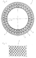
- the burner shown has a gas lance, not shown, which is surrounded by a recuperator 2.
- the latter consists of an annular air duct 3 and an annular exhaust duct 4, these being separated from one another by a tubular, heat-transmitting wall 5.
- a tubular mat 6 made of heat-resistant material is placed in each of the air duct 3 and the exhaust duct 4.
- the mat 6 consists of wire and has a structure, as can be seen in particular from FIG. 2.
- the mats 6 heat up and cause heat transfer by radiation. This increases with increasing temperature in the fourth power, compared to the linear increase in convective heat transfer. From 900 ° C upwards, the recuperator efficiency exceeds that of a finned heat exchanger.
- the mats 6 occupy approximately 5% of the free passage cross section of the air duct 3 or the exhaust duct 4. Due to this fact and their already low flow resistance, the pressure loss is comparatively low. Accordingly, a fan with a weaker dimension is used.
- the burner shown schematically consists of ceramic material.
- the invention is also applicable to Steel structures. Above all, it can be used in radiant heating pipes.
- a mat of carbon fibers or a structure made of wire coils pushed into one another can be used.
- the diameter of the carbon fibers or wire is approximately 1.2 mm.
- Heat-resistant plastic fibers can also be used.
Abstract
Description
Die Erfindung betrifft einen Rekuperatorbrenner mit einer ringförmigen Abgasführung und einer ringförmigen Luftführung, die durch eine rohrförmige, wärmeübertragende Wand voneinander getrennt sind.The invention relates to a recuperator burner with an annular exhaust gas duct and an annular air duct, which are separated from one another by a tubular, heat-transmitting wall.
Bei derartigen Brennern hängt die Wärmeübertragung im Rekuperator von der wärmeübertragenden Fläche, den Gasgeschwindigkeiten und der Temperaturdifferenz ab. Letztere kann im stationären Betriebszustand als konstant angesetzt werden. Die Gasgeschwindigkeiten können zur Erhöhung des Wärmeübergangs gesteigert werden, jedoch nur in gewissen Grenzen, da die Druckverluste mit dem Quadrat der Gasgeschwindigkeiten ansteigen. Zur Vergrößerung der wärmeübertragenden Fläche ist es bekannt, diese mit Rippen zu versehen oder als Faltenbalg derart auszubilden, daß Abgasführungskanäle und Luftführungskanäle einander in Umfangsrichtung abwechseln.With such burners, the heat transfer in the recuperator depends on the heat transfer surface, the gas velocities and the temperature difference. The latter can be assumed to be constant in the stationary operating state. The gas velocities can be increased to increase the heat transfer, but only within certain limits, since the pressure losses increase with the square of the gas velocities. To increase the heat transfer surface, it is known to provide it with ribs or to form it as a bellows in such a way that exhaust gas conduction channels and air conduction channels alternate in the circumferential direction.
Der Erfindung liegt die Aufgabe zugrunde, die Wärmeübertragung im Rekuperator mit einfachen und kostengünstigen Mitteln weiter zu steigern.The invention has for its object to further increase the heat transfer in the recuperator with simple and inexpensive means.
Zur Lösung dieser Aufgabe ist der Rekuperatorbrenner nach der Erfindung dadurch gekennzeichnet, daß in die Abgasführung und/oder in die Luftführung eine rohrförmige Matte aus hitzebeständigem Material eingelegt ist.To achieve this object, the recuperative burner according to the invention is characterized in that a tubular mat made of heat-resistant material is inserted into the exhaust gas duct and / or into the air duct.
Während des Betriebes erwärmen sich die Matten und übertragen einen Teil der Wärme durch Strahlung. Der Wärmeübergang im Rekuperator findet also nicht vorwiegend durch Konvektion statt, sondern zum Teil auch durch Strahlung.During operation, the mats heat up and transfer some of the heat through radiation. The heat transfer in the recuperator does not mainly take place through convection, but also partly through radiation.
Es wurde gefunden, daß die filigrane Struktur der Matte zu einem ständigen Aufreißen der Strömung führt, so daß sich keine Grenzschicht aufbauen kann. Bei gleichem Massenstrom ergibt sich im Vergleich zu einer durchgehenden Fläche ein vielfach höheres Auftreffen von Masseteilchen auf der Matte mit entsprechend höherer Wärmeübertragung. Daraus resultiert die intensive Strahlung der Matte. Grundsätzlich gilt, je feiner die Filigranstruktur, desto höher der Wärmestrahlungsanteil und desto besser der Rekuperator-Wirkungsgrad.It has been found that the filigree structure of the mat leads to a constant tearing of the flow, so that no boundary layer can build up. With the same mass flow, there is a much higher impact of mass particles on the mat compared to a continuous surface with correspondingly higher heat transfer. This results in the intense radiation of the mat. Basically, the finer the filigree structure, the higher the heat radiation and the better the recuperator efficiency.
Bei ca. 900°C entspricht der Rekuperator-Wirkungsgrad des erfindungsgemäßen Brenners etwa dem eines Rippenrekuperators. Der Glattrohrrekuperator kompensiert hier also die wesentlich größere Wärmetauscherfläche des Rippenrekuperators. Oberhalb dieser Temperatur steigt der Wirkungsgrad gegenüber dem eines Rippenrekuperators an, wobei der Unterschied mit zunehmender Temperatur zunimmt, da die Strahlung nicht linear, sondern nach dem T4-Gesetz ansteigt. Als wesentlicher weiterer Vorteil, der sich über den gesamten Temperaturbereich auswirkt, sind die geringen Herstellungskosten und das geringe Gewicht der Matte zu nennen. Auch vorhandene Glattrohr-Rekuperatoren lassen sich ohne weiteres nachrüsten.At approx. 900 ° C the recuperator efficiency of the burner according to the invention corresponds approximately to that of a fin recuperator. The smooth tube recuperator thus compensates for the much larger heat exchanger area of the fin recuperator. Above this temperature, the efficiency increases compared to that of a fin recuperator, the difference increasing with increasing temperature, since the radiation does not increase linearly but according to the T 4 law. Another important advantage that affects the entire temperature range is the low manufacturing costs and the low weight of the mat. Existing smooth tube recuperators can also be easily retrofitted.
Hauptanwendungsgebiet der Erfindung sind keramische Brenner, die aus fertigungstechnischen Gründen Glattrohr-Rekuperatoren aufweisen. Deren Wirkungsgrad beträgt lediglich 70 %, bezogen auf den Wirkungsgrad eines Rippenrekuperators. Da die Matte den Wirkungsgrad im oberem Temperaturbereich über den eines Rippenrekuperators anhebt, ist die erzielte Steigerung bei Keramikbrennern daher besonders hervorstechend.The main field of application of the invention is ceramic burners which have smooth tube recuperators for manufacturing reasons. Their efficiency is only 70%, based on the efficiency of a fin recuperator. Since the mat raises the efficiency in the upper temperature range above that of a fin recuperator, the increase achieved in ceramic burners is particularly striking.
Der Strömungswiderstand der Matte ist relativ gering. Dies gilt insbesondere dann, wenn die Matte weniger als ca. 10 % des freien Durchtrittsquerschnitt der Abgasführung bzw. der Luftführung einnimmt. Der geringe Druckverlust läßt relativ niedrige Strömungsgeschwindigkeiten zu, so daß mit leistungsschwächeren Gebläsen gearbeitet werden kann.The flow resistance of the mat is relatively low. This applies in particular if the mat occupies less than approx. 10% of the free passage cross section of the exhaust gas duct or the air duct. The low pressure drop allows relatively low flow speeds, so that less powerful fans can be used.
Dabei besteht ohne weiteres die vorteilhafte Möglichkeit, die Matte mehrlagig auszubilden.In this case, there is readily the advantageous possibility of forming the mat in multiple layers.
Ferner wird vorgeschlagen, daß die Matte aus Draht besteht, z.B. aus ineinander geschobenen Drahtwedeln. Hier ist, der Herstellungsaufwand ganz besonders gering.It is also proposed that the mat be made of wire, for example of wire wedges pushed into one another. Here, the manufacturing effort is very low.
Alternativ kann es vorteilhaft sein, daß die Matte aus Kohlestoffasern besteht. Vorzugsweise ist der Durchmesser der Kohlestoffasern bzw. des Drahtes kleiner als 3 mm, vorzugsweise ca. 1,2 mm. Es wurden gefunden, daß auf diese Weise Druckverlust und Strahlungsintensität optimiert werden können.Alternatively, it may be advantageous for the mat to consist of carbon fibers. The diameter of the carbon fibers or of the wire is preferably less than 3 mm, preferably approximately 1.2 mm. It has been found that pressure loss and radiation intensity can be optimized in this way.
Die Erfindung wird anhand eines bevorzugten Ausführungsbeispiels im Zusammenhang mit der beiliegenden Zeichnung näher erläutert. Die Zeichnung zeigt in:
- Fig. 1
- einen schematischen Querschnitt durch einen Rekuperator-Brenner nach der Erfindung;
- Fig. 2
- eine Teil-Seitenansicht einer rohrförmigen Matte.
- Fig. 1
- a schematic cross section through a recuperator burner according to the invention;
- Fig. 2
- a partial side view of a tubular mat.
Der dargestellte Brenner weist eine nicht gezeigte Gaslanze auf, die von einem Rekuperator 2 umgeben ist. Letzterer besteht aus einer ringförmigen Luftführung 3 und einer ringförmigen Abgasführung 4, wobei diese durch eine rohrförmige, wärmeübertragende Wand 5 voneinander getrennt sind.The burner shown has a gas lance, not shown, which is surrounded by a
In die Luftführung 3 und in die Abgasführung 4 ist je eine rohrförmige Matte 6 aus hitzebeständigem Material eingelegt. Die Matte 6 besteht im vorliegenden Fall aus Draht und weist eine Struktur auf, wie sie insbesondere aus Fig. 2 hervorgeht.A
Während des Betriebes erwärmen sich die Matten 6 und bewirken eine Wärmeübertragung durch Strahlung. Diese erhöht sich mit steigender Temperatur in der vierten Potenz, verglichen mit der linearen Erhöhung einer konvektiven Wärmeübertragung. Von 900°C aufwärts übersteigt der Rekuperator-Wirkungsgrad den eines Rippenwärmetauschers.During operation, the
Die Matten 6 nehmen ca. 5 % des freien Durchtrittsquerschnitts der Luftführung 3 bzw. der Abgasführung 4 ein. Aufgrund dieser Tatsache und ihres ohnehin geringen Strömungswiderstandes ist der Druckverlust vergleichsweise gering. Dementsprechend wird mit einem schwächer dimensionierten Gebläse gearbeitet.The
Der schematisch dargestellte Brenner besteht aus keramischem Material. Die Erfindung ist jedoch auch anwendbar auf Stahlkonstruktionen. Vor allen Dingen läßt sie sich in Strahlheizrohren einsetzen.The burner shown schematically consists of ceramic material. However, the invention is also applicable to Steel structures. Above all, it can be used in radiant heating pipes.
Im Rahmen der Erfindung sind durchaus Abwandlungsmöglichkeiten gegeben. So kann anstelle der gezeigten Matte eine Matte Kohlenstoffasern oder eine Struktur aus ineinander geschobenen Drahtwendeln eingesetzt werden. Der Durchmesser der Kohlenstoffasern bzw. des Drahtes beträgt dabei ca. 1,2 mm. Auch hitzebeständige Kunststoffasern können zur Anwendung kommen.In the context of the invention, there are quite a number of possible modifications. Instead of the mat shown, a mat of carbon fibers or a structure made of wire coils pushed into one another can be used. The diameter of the carbon fibers or wire is approximately 1.2 mm. Heat-resistant plastic fibers can also be used.
Claims (7)
dadurch gekennzeichnet,
daß in die Abgasführung (4) und/oder in die Luftführung (3) eine rohrförmige Matte (6) aus hitzebeständigem Material eingelegt ist.Recuperator burner with an annular exhaust gas duct (4) and an annular air duct (3), which are separated from one another by a tubular, heat-transmitting wall (5),
characterized,
that a tubular mat (6) made of heat-resistant material is inserted into the exhaust duct (4) and / or into the air duct (3).
Applications Claiming Priority (2)
| Application Number | Priority Date | Filing Date | Title |
|---|---|---|---|
| DE1995118296 DE19518296A1 (en) | 1995-05-18 | 1995-05-18 | Recuperator burner |
| DE19518296 | 1995-05-18 |
Publications (2)
| Publication Number | Publication Date |
|---|---|
| EP0743500A2 true EP0743500A2 (en) | 1996-11-20 |
| EP0743500A3 EP0743500A3 (en) | 1997-11-26 |
Family
ID=7762273
Family Applications (1)
| Application Number | Title | Priority Date | Filing Date |
|---|---|---|---|
| EP96106942A Withdrawn EP0743500A3 (en) | 1995-05-18 | 1996-05-03 | Recuprerative burner |
Country Status (2)
| Country | Link |
|---|---|
| EP (1) | EP0743500A3 (en) |
| DE (1) | DE19518296A1 (en) |
Cited By (5)
| Publication number | Priority date | Publication date | Assignee | Title |
|---|---|---|---|---|
| EP0854345A1 (en) * | 1997-01-21 | 1998-07-22 | VIESSMANN WERKE GmbH & CO. | Heat exchanger |
| WO1998031976A1 (en) * | 1997-01-21 | 1998-07-23 | Viessmann Werke Gmbh & Co. | Heat exchanger element |
| DE19961284A1 (en) * | 1999-12-18 | 2001-07-12 | Bosch Gmbh Robert | Heat exchanger or gas heating appliance, in particular waste heat appliances, comprised of tubes enclosed in tubular sleeve of knitted fabric made of wire threads |
| US8986001B2 (en) | 2009-12-16 | 2015-03-24 | Eclipse, Inc. | Burner with improved heat recuperator |
| EP3133344A1 (en) * | 2015-08-20 | 2017-02-22 | AICHELIN Holding GmbH | Recuperative burner with ceramic recuperator and a method for producing same |
Families Citing this family (1)
| Publication number | Priority date | Publication date | Assignee | Title |
|---|---|---|---|---|
| DE102011103106A1 (en) | 2011-05-25 | 2012-11-29 | Erbicol S.A. | Heat exchanger made of ceramic material, in particular for recuperative burners, and method for its production |
Family Cites Families (17)
| Publication number | Priority date | Publication date | Assignee | Title |
|---|---|---|---|---|
| DE1069165B (en) * | 1959-11-19 | GEA-Luftkuhl'er-Gcsellschaft m.b. H., Bochum | Tubular heat exchanger for flowing media with sheet metal helically wound in the tubes and along the axis of the tube | |
| AT19301B (en) * | 1903-09-15 | 1905-02-25 | Ignaz Wasniczek | |
| DE567819C (en) * | 1929-06-22 | 1933-01-10 | Aeg | Firing, especially for steam boilers |
| DE975537C (en) * | 1948-04-28 | 1962-01-11 | Svenska Maskinverken Ab | Heat exchanger |
| FR1026192A (en) * | 1949-09-19 | 1953-04-24 | Process for manufacturing heat exchangers and heat exchangers otenus in accordance with said process | |
| DE1097461B (en) * | 1959-05-16 | 1961-01-19 | Daimler Benz Ag | Process for cleaning regenerative heat exchangers |
| FR1274532A (en) * | 1960-09-06 | 1961-10-27 | Teikoku Sanso Kabushiki Kaisha | New lined regenerators and coiled tubular bundle |
| GB1056104A (en) * | 1962-07-20 | 1967-01-25 | Oestbo John D B | Improvements in or relating to heat-exchangers, pre-heaters and economizers |
| FR2453381A1 (en) * | 1979-04-03 | 1980-10-31 | Ferodo Sa | Heat exchanger having tubes wrapped with wire - carries number of U-strips to increase surface area of tubes |
| DE2948048C2 (en) * | 1979-11-29 | 1981-10-08 | Aichelin GmbH, 7015 Korntal | Industrial burners |
| DE3017574C2 (en) * | 1980-05-08 | 1985-06-05 | Wieland-Werke Ag, 7900 Ulm | Spacers for coaxial heat exchangers |
| US4432408A (en) * | 1982-07-19 | 1984-02-21 | The Dow Chemical Co. | Method and compressed vermicular expanded graphite apparatus for heat exchanging |
| GB2137332B (en) * | 1983-03-29 | 1986-06-18 | Arrenshaw | Improvements in or relating to heat exchangers |
| ATE61651T1 (en) * | 1986-06-16 | 1991-03-15 | Lorraine Carbone | THERMAL COMPOUND WITH STRONG TRANSFER COEFFICIENT AND USES TO COOL DOWN AN ARRANGEMENT SUBJECT TO INTENSE THERMAL FLOW. |
| US5211219A (en) * | 1990-07-31 | 1993-05-18 | Daikin Industries, Ltd. | Air conditioner |
| DE4132236C1 (en) * | 1991-09-27 | 1992-10-15 | Ws Waermeprozesstechnik Gmbh, 7253 Renningen, De | |
| US5390734A (en) * | 1993-05-28 | 1995-02-21 | Lytron Incorporated | Heat sink |
-
1995
- 1995-05-18 DE DE1995118296 patent/DE19518296A1/en not_active Withdrawn
-
1996
- 1996-05-03 EP EP96106942A patent/EP0743500A3/en not_active Withdrawn
Non-Patent Citations (1)
| Title |
|---|
| None |
Cited By (5)
| Publication number | Priority date | Publication date | Assignee | Title |
|---|---|---|---|---|
| EP0854345A1 (en) * | 1997-01-21 | 1998-07-22 | VIESSMANN WERKE GmbH & CO. | Heat exchanger |
| WO1998031976A1 (en) * | 1997-01-21 | 1998-07-23 | Viessmann Werke Gmbh & Co. | Heat exchanger element |
| DE19961284A1 (en) * | 1999-12-18 | 2001-07-12 | Bosch Gmbh Robert | Heat exchanger or gas heating appliance, in particular waste heat appliances, comprised of tubes enclosed in tubular sleeve of knitted fabric made of wire threads |
| US8986001B2 (en) | 2009-12-16 | 2015-03-24 | Eclipse, Inc. | Burner with improved heat recuperator |
| EP3133344A1 (en) * | 2015-08-20 | 2017-02-22 | AICHELIN Holding GmbH | Recuperative burner with ceramic recuperator and a method for producing same |
Also Published As
| Publication number | Publication date |
|---|---|
| EP0743500A3 (en) | 1997-11-26 |
| DE19518296A1 (en) | 1996-11-21 |
Similar Documents
| Publication | Publication Date | Title |
|---|---|---|
| DE2706728A1 (en) | HEAT EXCHANGER FOR A STIRLING ENGINE, IN PARTICULAR FOR MOTOR VEHICLES | |
| WO1992020975A1 (en) | Air heater | |
| EP0743500A2 (en) | Recuprerative burner | |
| DE2321926A1 (en) | BOILERS FOR HEATING OR EVAPORATING LIQUIDS | |
| AT410370B (en) | HEAT EXCHANGER AND METHOD FOR THE PRODUCTION THEREOF | |
| EP0337923B1 (en) | Water heater | |
| EP0065944A1 (en) | Tiled stove | |
| DE3304868C2 (en) | Water heater | |
| DE2538824A1 (en) | PROCESS FOR MORE EFFICIENT USE OF WASTE HEAT FROM WASTE INCINERATION PLANTS AND DEVICE | |
| DE1910548U (en) | HEAT EXCHANGER HIGH LENGTH FLOW ELEMENT. | |
| EP0711954B1 (en) | Air/flue gas stack | |
| DE4032264C2 (en) | Device for the recovery of heat from the exhaust gases from combustion plants and production processes | |
| DE3117533A1 (en) | Recuperator, preferably for industrial furnaces | |
| DE277757C (en) | ||
| AT346539B (en) | OVEN WITH BUILT-IN GAS BURNER | |
| DE2748576C3 (en) | Regenerative heater | |
| EP2550498A1 (en) | Furnace for the heat treatment of a multiplicity of items | |
| WO1996009499A1 (en) | Heating boiler | |
| DE2832442C2 (en) | Heating furnace | |
| AT397497B (en) | FIREPROOF MATERIAL SETTING STONE FOR GRILLING AND GRILLING | |
| DE2952564C1 (en) | Boiler | |
| DE2807167A1 (en) | Combustion air supply for boiler - has casing contiguous with gas flow reversing chamber and bottom plate to guide air into burner | |
| AT167140B (en) | Rotary drum as a heat exchanger for systems for burning cement, alkaline earth compounds, etc. like | |
| DE3023238A1 (en) | ELECTRICALLY HEATED OVEN WITH ROD-SHAPED HEATING ELEMENTS | |
| DE1526918C3 (en) |
Legal Events
| Date | Code | Title | Description |
|---|---|---|---|
| PUAI | Public reference made under article 153(3) epc to a published international application that has entered the european phase |
Free format text: ORIGINAL CODE: 0009012 |
|
| AK | Designated contracting states |
Kind code of ref document: A2 Designated state(s): AT BE CH DE FR GB IT LI LU |
|
| PUAL | Search report despatched |
Free format text: ORIGINAL CODE: 0009013 |
|
| AK | Designated contracting states |
Kind code of ref document: A3 Designated state(s): AT BE CH DE FR GB IT LI LU |
|
| 17P | Request for examination filed |
Effective date: 19971209 |
|
| ET | Fr: translation filed | ||
| RAP1 | Party data changed (applicant data changed or rights of an application transferred) |
Owner name: L B E FEUERUNGSTECHNIK GMBH |
|
| 17Q | First examination report despatched |
Effective date: 20000412 |
|
| STAA | Information on the status of an ep patent application or granted ep patent |
Free format text: STATUS: THE APPLICATION IS DEEMED TO BE WITHDRAWN |
|
| 18D | Application deemed to be withdrawn |
Effective date: 20000823 |