EP0758168A1 - Variable rate transmitting method, and transmitter and receiver using it - Google Patents
Variable rate transmitting method, and transmitter and receiver using it Download PDFInfo
- Publication number
- EP0758168A1 EP0758168A1 EP96903224A EP96903224A EP0758168A1 EP 0758168 A1 EP0758168 A1 EP 0758168A1 EP 96903224 A EP96903224 A EP 96903224A EP 96903224 A EP96903224 A EP 96903224A EP 0758168 A1 EP0758168 A1 EP 0758168A1
- Authority
- EP
- European Patent Office
- Prior art keywords
- data
- frame
- transmitted
- transmitted data
- error detecting
- Prior art date
- Legal status (The legal status is an assumption and is not a legal conclusion. Google has not performed a legal analysis and makes no representation as to the accuracy of the status listed.)
- Granted
Links
Images


Classifications
-
- H—ELECTRICITY
- H04—ELECTRIC COMMUNICATION TECHNIQUE
- H04L—TRANSMISSION OF DIGITAL INFORMATION, e.g. TELEGRAPHIC COMMUNICATION
- H04L1/00—Arrangements for detecting or preventing errors in the information received
- H04L1/004—Arrangements for detecting or preventing errors in the information received by using forward error control
- H04L1/0045—Arrangements at the receiver end
- H04L1/0046—Code rate detection or code type detection
-
- H—ELECTRICITY
- H04—ELECTRIC COMMUNICATION TECHNIQUE
- H04B—TRANSMISSION
- H04B1/00—Details of transmission systems, not covered by a single one of groups H04B3/00 - H04B13/00; Details of transmission systems not characterised by the medium used for transmission
- H04B1/69—Spread spectrum techniques
- H04B1/707—Spread spectrum techniques using direct sequence modulation
-
- H—ELECTRICITY
- H04—ELECTRIC COMMUNICATION TECHNIQUE
- H04B—TRANSMISSION
- H04B7/00—Radio transmission systems, i.e. using radiation field
- H04B7/24—Radio transmission systems, i.e. using radiation field for communication between two or more posts
- H04B7/26—Radio transmission systems, i.e. using radiation field for communication between two or more posts at least one of which is mobile
- H04B7/2628—Radio transmission systems, i.e. using radiation field for communication between two or more posts at least one of which is mobile using code-division multiple access [CDMA] or spread spectrum multiple access [SSMA]
-
- H—ELECTRICITY
- H04—ELECTRIC COMMUNICATION TECHNIQUE
- H04J—MULTIPLEX COMMUNICATION
- H04J3/00—Time-division multiplex systems
- H04J3/02—Details
- H04J3/14—Monitoring arrangements
-
- H—ELECTRICITY
- H04—ELECTRIC COMMUNICATION TECHNIQUE
- H04J—MULTIPLEX COMMUNICATION
- H04J3/00—Time-division multiplex systems
- H04J3/16—Time-division multiplex systems in which the time allocation to individual channels within a transmission cycle is variable, e.g. to accommodate varying complexity of signals, to vary number of channels transmitted
- H04J3/1682—Allocation of channels according to the instantaneous demands of the users, e.g. concentrated multiplexers, statistical multiplexers
-
- H—ELECTRICITY
- H04—ELECTRIC COMMUNICATION TECHNIQUE
- H04L—TRANSMISSION OF DIGITAL INFORMATION, e.g. TELEGRAPHIC COMMUNICATION
- H04L1/00—Arrangements for detecting or preventing errors in the information received
- H04L1/0001—Systems modifying transmission characteristics according to link quality, e.g. power backoff
- H04L1/0002—Systems modifying transmission characteristics according to link quality, e.g. power backoff by adapting the transmission rate
-
- H—ELECTRICITY
- H04—ELECTRIC COMMUNICATION TECHNIQUE
- H04L—TRANSMISSION OF DIGITAL INFORMATION, e.g. TELEGRAPHIC COMMUNICATION
- H04L1/00—Arrangements for detecting or preventing errors in the information received
- H04L1/0001—Systems modifying transmission characteristics according to link quality, e.g. power backoff
- H04L1/0006—Systems modifying transmission characteristics according to link quality, e.g. power backoff by adapting the transmission format
- H04L1/0007—Systems modifying transmission characteristics according to link quality, e.g. power backoff by adapting the transmission format by modifying the frame length
-
- H—ELECTRICITY
- H04—ELECTRIC COMMUNICATION TECHNIQUE
- H04L—TRANSMISSION OF DIGITAL INFORMATION, e.g. TELEGRAPHIC COMMUNICATION
- H04L1/00—Arrangements for detecting or preventing errors in the information received
- H04L1/0001—Systems modifying transmission characteristics according to link quality, e.g. power backoff
- H04L1/0009—Systems modifying transmission characteristics according to link quality, e.g. power backoff by adapting the channel coding
- H04L1/0013—Rate matching, e.g. puncturing or repetition of code symbols
-
- H—ELECTRICITY
- H04—ELECTRIC COMMUNICATION TECHNIQUE
- H04L—TRANSMISSION OF DIGITAL INFORMATION, e.g. TELEGRAPHIC COMMUNICATION
- H04L1/00—Arrangements for detecting or preventing errors in the information received
- H04L1/0001—Systems modifying transmission characteristics according to link quality, e.g. power backoff
- H04L1/0036—Systems modifying transmission characteristics according to link quality, e.g. power backoff arrangements specific to the receiver
- H04L1/0038—Blind format detection
-
- H—ELECTRICITY
- H04—ELECTRIC COMMUNICATION TECHNIQUE
- H04L—TRANSMISSION OF DIGITAL INFORMATION, e.g. TELEGRAPHIC COMMUNICATION
- H04L1/00—Arrangements for detecting or preventing errors in the information received
- H04L1/0001—Systems modifying transmission characteristics according to link quality, e.g. power backoff
- H04L1/0036—Systems modifying transmission characteristics according to link quality, e.g. power backoff arrangements specific to the receiver
- H04L1/0039—Systems modifying transmission characteristics according to link quality, e.g. power backoff arrangements specific to the receiver other detection of signalling, e.g. detection of TFCI explicit signalling
-
- H—ELECTRICITY
- H04—ELECTRIC COMMUNICATION TECHNIQUE
- H04L—TRANSMISSION OF DIGITAL INFORMATION, e.g. TELEGRAPHIC COMMUNICATION
- H04L1/00—Arrangements for detecting or preventing errors in the information received
- H04L1/004—Arrangements for detecting or preventing errors in the information received by using forward error control
- H04L1/0056—Systems characterized by the type of code used
- H04L1/0061—Error detection codes
- H04L1/0063—Single parity check
-
- H—ELECTRICITY
- H04—ELECTRIC COMMUNICATION TECHNIQUE
- H04L—TRANSMISSION OF DIGITAL INFORMATION, e.g. TELEGRAPHIC COMMUNICATION
- H04L1/00—Arrangements for detecting or preventing errors in the information received
- H04L1/004—Arrangements for detecting or preventing errors in the information received by using forward error control
- H04L1/0056—Systems characterized by the type of code used
- H04L1/0071—Use of interleaving
-
- H—ELECTRICITY
- H04—ELECTRIC COMMUNICATION TECHNIQUE
- H04L—TRANSMISSION OF DIGITAL INFORMATION, e.g. TELEGRAPHIC COMMUNICATION
- H04L1/00—Arrangements for detecting or preventing errors in the information received
- H04L1/0078—Avoidance of errors by organising the transmitted data in a format specifically designed to deal with errors, e.g. location
- H04L1/0079—Formats for control data
-
- H—ELECTRICITY
- H04—ELECTRIC COMMUNICATION TECHNIQUE
- H04L—TRANSMISSION OF DIGITAL INFORMATION, e.g. TELEGRAPHIC COMMUNICATION
- H04L1/00—Arrangements for detecting or preventing errors in the information received
- H04L1/0078—Avoidance of errors by organising the transmitted data in a format specifically designed to deal with errors, e.g. location
- H04L1/0086—Unequal error protection
-
- H—ELECTRICITY
- H04—ELECTRIC COMMUNICATION TECHNIQUE
- H04L—TRANSMISSION OF DIGITAL INFORMATION, e.g. TELEGRAPHIC COMMUNICATION
- H04L1/00—Arrangements for detecting or preventing errors in the information received
- H04L1/08—Arrangements for detecting or preventing errors in the information received by repeating transmission, e.g. Verdan system
-
- H—ELECTRICITY
- H04—ELECTRIC COMMUNICATION TECHNIQUE
- H04L—TRANSMISSION OF DIGITAL INFORMATION, e.g. TELEGRAPHIC COMMUNICATION
- H04L7/00—Arrangements for synchronising receiver with transmitter
- H04L7/04—Speed or phase control by synchronisation signals
- H04L7/048—Speed or phase control by synchronisation signals using the properties of error detecting or error correcting codes, e.g. parity as synchronisation signal
-
- H—ELECTRICITY
- H04—ELECTRIC COMMUNICATION TECHNIQUE
- H04B—TRANSMISSION
- H04B2201/00—Indexing scheme relating to details of transmission systems not covered by a single group of H04B3/00 - H04B13/00
- H04B2201/69—Orthogonal indexing scheme relating to spread spectrum techniques in general
- H04B2201/707—Orthogonal indexing scheme relating to spread spectrum techniques in general relating to direct sequence modulation
- H04B2201/70703—Orthogonal indexing scheme relating to spread spectrum techniques in general relating to direct sequence modulation using multiple or variable rates
- H04B2201/70705—Rate detection
-
- H—ELECTRICITY
- H04—ELECTRIC COMMUNICATION TECHNIQUE
- H04L—TRANSMISSION OF DIGITAL INFORMATION, e.g. TELEGRAPHIC COMMUNICATION
- H04L1/00—Arrangements for detecting or preventing errors in the information received
- H04L1/0001—Systems modifying transmission characteristics according to link quality, e.g. power backoff
- H04L1/0009—Systems modifying transmission characteristics according to link quality, e.g. power backoff by adapting the channel coding
-
- H—ELECTRICITY
- H04—ELECTRIC COMMUNICATION TECHNIQUE
- H04L—TRANSMISSION OF DIGITAL INFORMATION, e.g. TELEGRAPHIC COMMUNICATION
- H04L1/00—Arrangements for detecting or preventing errors in the information received
- H04L1/0001—Systems modifying transmission characteristics according to link quality, e.g. power backoff
- H04L1/0023—Systems modifying transmission characteristics according to link quality, e.g. power backoff characterised by the signalling
- H04L1/0025—Transmission of mode-switching indication
-
- H—ELECTRICITY
- H04—ELECTRIC COMMUNICATION TECHNIQUE
- H04L—TRANSMISSION OF DIGITAL INFORMATION, e.g. TELEGRAPHIC COMMUNICATION
- H04L1/00—Arrangements for detecting or preventing errors in the information received
- H04L1/0001—Systems modifying transmission characteristics according to link quality, e.g. power backoff
- H04L1/0023—Systems modifying transmission characteristics according to link quality, e.g. power backoff characterised by the signalling
- H04L1/0032—Without explicit signalling
-
- H—ELECTRICITY
- H04—ELECTRIC COMMUNICATION TECHNIQUE
- H04L—TRANSMISSION OF DIGITAL INFORMATION, e.g. TELEGRAPHIC COMMUNICATION
- H04L1/00—Arrangements for detecting or preventing errors in the information received
- H04L1/004—Arrangements for detecting or preventing errors in the information received by using forward error control
- H04L1/0056—Systems characterized by the type of code used
- H04L1/0059—Convolutional codes
-
- H—ELECTRICITY
- H04—ELECTRIC COMMUNICATION TECHNIQUE
- H04L—TRANSMISSION OF DIGITAL INFORMATION, e.g. TELEGRAPHIC COMMUNICATION
- H04L1/00—Arrangements for detecting or preventing errors in the information received
- H04L2001/0098—Unequal error protection
-
- Y—GENERAL TAGGING OF NEW TECHNOLOGICAL DEVELOPMENTS; GENERAL TAGGING OF CROSS-SECTIONAL TECHNOLOGIES SPANNING OVER SEVERAL SECTIONS OF THE IPC; TECHNICAL SUBJECTS COVERED BY FORMER USPC CROSS-REFERENCE ART COLLECTIONS [XRACs] AND DIGESTS
- Y02—TECHNOLOGIES OR APPLICATIONS FOR MITIGATION OR ADAPTATION AGAINST CLIMATE CHANGE
- Y02D—CLIMATE CHANGE MITIGATION TECHNOLOGIES IN INFORMATION AND COMMUNICATION TECHNOLOGIES [ICT], I.E. INFORMATION AND COMMUNICATION TECHNOLOGIES AIMING AT THE REDUCTION OF THEIR OWN ENERGY USE
- Y02D30/00—Reducing energy consumption in communication networks
- Y02D30/50—Reducing energy consumption in communication networks in wire-line communication networks, e.g. low power modes or reduced link rate
-
- Y—GENERAL TAGGING OF NEW TECHNOLOGICAL DEVELOPMENTS; GENERAL TAGGING OF CROSS-SECTIONAL TECHNOLOGIES SPANNING OVER SEVERAL SECTIONS OF THE IPC; TECHNICAL SUBJECTS COVERED BY FORMER USPC CROSS-REFERENCE ART COLLECTIONS [XRACs] AND DIGESTS
- Y02—TECHNOLOGIES OR APPLICATIONS FOR MITIGATION OR ADAPTATION AGAINST CLIMATE CHANGE
- Y02D—CLIMATE CHANGE MITIGATION TECHNOLOGIES IN INFORMATION AND COMMUNICATION TECHNOLOGIES [ICT], I.E. INFORMATION AND COMMUNICATION TECHNOLOGIES AIMING AT THE REDUCTION OF THEIR OWN ENERGY USE
- Y02D30/00—Reducing energy consumption in communication networks
- Y02D30/70—Reducing energy consumption in communication networks in wireless communication networks
Definitions
- the present invention relates to a code division multiple access (CDMA) in mobile communications systems, and more particularly to a variable rate transmission method, a transmitter and receiver using the same method, which can realize apparent variable rate transmission by transmitting data contained in frames of a fixed length at a constant transmission rate.
- CDMA code division multiple access
- the output data (transmitted data) from a voice codec undergoes primary modulation, followed by secondary modulation using a pseudorandom sequence (spreading code sequence), to be spectrum-spread to a wideband signal and transmitted.
- the bit rate of the spreading code sequence is called a chip rate, and is tens to hundreds of times faster than the transmission rate.
- the primary modulation uses binary or quadrature phase shift keying
- the secondary modulation uses binary phase shift keying.
- the information amount of a transmitted voice signal is not constant, but varies from time to time. Accordingly, the transmission rate can be changed by dividing the transmitted data into frames of a fixed duration, and by transmitting data of a variable bit length in each frame, thereby achieving effective transmission of information in each frame period. This can obviate useless transmission, thereby saving power consumption of the transmitter.
- the following method is taken to transmit data of a different transmission rate in the CDMA system.
- data whose transmission rate is lower than the frame transmission rate is transmitted using a part of transmission frames (see, for example, R. Padovani, "Reverse link performance of IS-95 based cellular systems", IEEE Personal Communications, vol.1, pp.28-34, 3rd Quarter 1994).
- data whose transmission rate is higher than the frame transmission rate is divided into a plurality of transmission channels, and the divided data are spread using different spreading codes to be transmitted.
- FEC Forward Error Correction
- the transmitting side transmits transmitted data (including the transmission rate information) which has undergone error correcting encoding
- the receiving side carries out the error correcting decoding followed by extraction of the transmission rate information to decide the effective data length in each received frame. Accordingly, the transmission rate information cannot be obtained until the end of the error correcting decoding.
- the decoding is performed before deciding the data length to be decoded, and hence the error correction cannot fully achieve its effect.
- the transmitted data includes data of various degrees of importance.
- TDMA Time Division Multiple Access
- RCR Physical digital cellular telecommunication system RCR standard, RCR STD-27
- Research & Development Center for Radio System This method, however, lacks flexibility to transmit various data of different transmission rates.
- high speed data is divided and spread to a plurality of signals using different spreading codes, and the spread signals are combined to be transmitted.
- the transmitting side must periodically inserts pilot symbols into transmitted data (see, for example, S. Sampei, "Fading Compensation for 16QAM in Land Mobile Communications", The Transactions of the Institute of Electronics, Information and Communication Engineers of Japan B-II, Vol. J72-B-II pp. 7-15, January 1989, or its revised version, S. Sampei, et al. "Rayleigh Fading Compensation for QAM in Land Mobile Radio Communications", IEEE Transactions on Vehicular Technology, VOL. 42. No. 2, MAY 1993).
- This method will make it necessary for the plurality of transmission channels to send the same pilot symbols when the method is applied to the signals spread with the plurality of the spreading codes.
- the respective channels experience the same fading, and hence it is unnecessary to send the pilot symbols through the plurality of channels. Since multiple users share the same frequency band in CDMA, transmission of superfluous signals will reduce the number of users that can be accommodated in a limited frequency band because it will increase interference to other users by an amount corresponding to the transmission power necessary to send the superfluous signals.
- the high speed signal must be divided into a plurality of signals followed by spreading using different spreading codes and by combining of the spread signals, and the combined signal is converted into a radio frequency band followed by power amplification to be transmitted. If the plurality of spread signals are combined in the same phase, the amplitude of the combined signal will increase in proportion to the number of divided signals. This will require a high peak power liner transmission power amplifier. Such a power amplifier demanding large power consumption is unsuitable to portable telephones which require low power consumption.
- An object of the present invention is to provide a variable rate transmission method, a transmitter and a receiver using the same method, which make it possible to freely change the transmission rate without providing a receiving side with the transmission rate information of transmitted data.
- Another object of the present invention is to provide a variable rate transmission method, a transmitter and a receiver, which can achieve data protection in accordance with the degree of importance of the data constituting in the transmitted data.
- Still another object of the present invention is to provide a variable rate transmission method, a transmitter and a receiver that can flexibly send data over a wide range from low to high rate.
- variable rate transmission method which varies an average transmission rate by transmitting each frame of a fixed duration, the frame holding transmitted data of a variable length, wherein a transmitting side comprising the steps of:
- the step of detecting the error detecting code sequentially may divide received data in the each frame by predetermined data while shifting the received data bit by bit, and may decide that the error detecting code is detected at a point at which the received data can be divided.
- the step of recovering the transmitted data may decide an end bit position of the transmitted data at a point preceding the point at which the error detecting code is detected by the number of bits of the error detecting code.
- the transmitting side may further comprise the steps of:
- the method may be CDMA (Code Division Multiple Access), in which the transmitting side comprises the steps of performing primary modulation of the transmitted data and the error detecting code, and performing secondary modulation of a signal which has undergone the primary modulation using a spreading code sequence.
- CDMA Code Division Multiple Access
- Transmission power of the pilot symbols and the important data may be increased.
- the transmitting side may comprise the steps of:
- the transmitting side may comprise the steps of: allocating each frame of a plurality of channels with the transmitted data;
- Data of the plurality of channels may be transmitted with a phase of a carrier of each of the plurality of channels being shifted.
- the important data may be control data.
- the transmitting side may comprise the step of disposing the error detecting code at a fixed position in the each frame, and the receiving side comprises the steps of extracting the error detecting code placed at the fixed position in the each frame, and obtaining the number of bits of the transmitted data on the basis of the error detecting code.
- the method may be a CDMA data transmission method in which the transmitting side comprises the steps of performing primary modulation of the transmitted data and the error detecting code in the each frame, and performing secondary modulation of primary modulated data in each frame by using a spreading code sequence, to be transmitted.
- the transmitting side may comprise the step of performing error correcting encoding and interleaving of the transmitted data before the primary modulation, and wherein the receiving side comprises the steps of performing a primary demodulation of the transmitted data which is received, and performing deinterleaving and error correcting decoding of the transmitted data which have undergone the primary demodulation.
- the transmitting side may comprise the steps of:
- the transmitting side may comprise the step of:
- Transmission method may be a CDMA data transmission method in which the transmitting side comprises the steps of performing primary modulation of the transmitted data and the error detecting code in the each frame, and performing secondary modulation of primary modulated data in each frame by using a spreading code sequence, to be transmitted.
- the transmitting side may comprise the steps of:
- the transmitting side may comprise the step of:
- the transmitting side may comprise the steps of:
- the transmission method may comprise, when the number of bits of the transmitted data in the each frame is equal to or less than 1/K of the maximum number of bits of data that can be transmitted by the each frame, where K is a positive integer, at the transmitting side:
- a transmitter which varies an average transmission rate by transmitting each frame of a fixed duration, the frame holding transmitted data of a variable length, the transmitter comprising:
- the transmitter may further comprise:
- the data relocating means may dispose the important data near the pilot symbols by writing the transmitted data into the memory row by row with a length of M bits, and by reading the stored transmitted data from the memory column by column with a length of N bits, wherein N is the number of bits of a slot sandwiched by the pilot symbols, and M is the number of the slots contained in the each frame.
- the data relocating means may write the important data into the memory alternately from a top row and a bottom row of the memory.
- the transmitter may further comprise:
- the transmitter may further comprise a transmission power control means connected to the pilot symbol inserting means for controlling transmission power of data in the each frame in accordance with a degree of importance of the data.
- a predetermined particular code may be written in a blank in the each frame, the blank occurring when the number of bits of the transmitted data is less than the maximum number of bits of the each frame, and wherein the transmission power control means reduces transmission power of the blank to zero.
- the transmitter may further comprise a repeater preceding the memory for repeating the transmitted data and the error detecting code K times for each bit, and wherein the transmission power control means reduces transmission power of the each frame to 1/K as compared with transmission power used when the K time repeating is not performed.
- the transmitter may further comprise:
- the transmitter may further comprise a plurality of phase controllers each connected after the plurality of primary modulators for shifting phases of carriers of the secondary modulators.
- the transmitter may further comprise means for adding the error detecting code to a fixed position in the each frame.
- the transmitter may further comprise:
- the transmitter may further comprise:
- the transmitter may further comprise adding means for adding, to a fixed position of the each frame, transmission rate information representative of the total number of data in the each frame, and the error detecting code.
- the transmitter may further comprise:
- the transmitter may further comprise means for adding the transmission rate information associated with a current frame to a fixed position in a preceding frame.
- the transmitter may further comprise:
- a receiver comprising:
- the means for detecting the error detecting code sequentially may divide received data in each the frame by predetermined data while shifting the received data bit by bit, and may decide that the error detecting code is detected at a point at which the received data can be divided.
- the receiver may further comprise:
- the data relocating means may rearrange the data in the each frame into the original order by writing the data in the each frame into the memory column by column with a length of N bits, and by reading the stored data of the each frame from the memory row by row with a length of M bits, wherein N is the number of bits of a slot sandwiched by the pilot symbols, and M is the number of the slots contained in the each frame.
- the data relocating means may carry out reading of the memory alternately from a top row and a bottom row of the memory.
- the receiver may further comprise:
- the receiver may further comprise:
- the receiver may further comprise:
- the receiver may further comprise phase controllers each provided for each one of the channels for correcting phases of the multiple series of data.
- the receiver may further comprise:
- the receiver may further comprise:
- the receiver may further comprise:
- the receiver may further comprise:
- the means for deciding may determine the end bit position of the transmitted data in a current frame in accordance with the transmission rate information received in a preceding frame.
- the receiver may further comprise:
- the receiver may further comprise, when the number of bits of data in the each frame is equal to or less than 1/K of a maximum number of bits that can be transmitted by one frame, where K is a positive integer:
- variable rate transmission method comprising the steps of:
- the step of disposing the important data near the pilot symbols may comprise the steps of:
- the method may be a CDMA data transmission method in which the transmitting side comprises the steps of performing primary modulation of the transmitted data and the error detecting code in the each frame, and performing secondary modulation of primary modulated data in each frame by using a spreading code sequence.
- the transmission power of the pilot symbols and the important data may be increased.
- the transmission rate is estimated at the receiving side in response to the error detecting information, it is unnecessary to send the transmission rate information from the transmitting side to the receiving side. This makes it possible to transmit data whose transmission rate changes frame by frame during communications.
- providing the receiving side with the transmission rate information can achieve higher reliability variable rate transmission.
- mapping the important data close to the pilot symbols in the present invention can achieve the data protection in accordance with the degree of importance of the data. This is because the data error rate is small in the neighborhood of the pilot symbols as will be described later.
- Repeating the transmission of respective bits of the transmitted data can prevent burst transmission in the present invention even when the number of bits in a frame is much smaller than the maximum bit number of the frame, that is, even when the transmission rate of the transmitted data is much lower than the maximum transmission rate of the frame.
- the data can be transmitted at a high rate, and the interference power to other users can be reduced.
- the CDMA system in accordance with the present invention can transmit the pilot symbols and control data through one of a plurality of channels, the other of which transmit high speed data.
- the transmission signals of respective channels can combined after their phases are shifted, the peak of the transmission power can be limited, which in turn will reduce the interference power to other users.
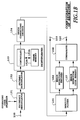
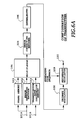
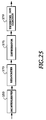
- Figs. 1A and 1B are block diagrams showing a first embodiment of a transmitter and a receiver using the variable rate transmission method in accordance with the present invention.
- Fig. 1A shows the configuration of the transmitter.
- a transmitted data sequence applied to an input terminal 101A is delivered to an error detecting encoder 102 and a frame memory 103.
- the frame memory 103 holds the data with the number of bits to be transmitted in one frame period.
- the error detecting encoder 102 calculates the error detecting code (CRC bits, for example) of the transmitted data of one frame.
- a multiplexer 104 outputs for each frame a data sequence consisting of the calculated error detecting code followed by the transmitted data.
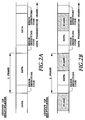
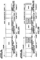
- Figs. 2A and 2B illustrate the data sequences output from the multiplexer 104.
- Fig. 2A illustrates the data sequence when the transmission rate of the data is maximum
- Fig. 2B illustrates the data sequence when the transmission rate is less than the maximum.
- an idle time (a blank) takes place in each frame when the transmission rate is less than the maximum rate.
- the error detecting code is inserted at a fixed position in each frame. For example, in Figs. 2A and 2B, it is placed at the initial position of the frame.
- the data sequence of one frame, into which the error detecting code is inserted undergoes error correcting encoding through an error correcting encoder 105, and is input to an interleaver 106.
- the interleaver 106 includes a controller 106A and a frame memory 106B.
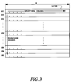
- Fig. 3 is a schematic diagram illustrating the frame memory 106B of the interleaver 106.
- the interleaver 106 reads the data sequence of one frame in a direction different from that of writing to the frame memory 106B. That is, the interleaver 106 reads in the direction of columns the transmitted data which has been written in the direction of rows of the frame memory 106B. The data sequence thus interleaved is rewritten in the other side of the frame memory 106B.
- numbers #1 - #N attached to the left of the frame memory 106B indicate the order of writing the data, which will be described later in the sixth embodiment.
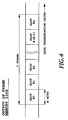
- Fig. 4 illustrates the frame structure of the data sequence output from the frame memory 106B.
- the data segments corresponding to individual rows of the frame memory 106B are called slots. Accordingly, if one side of the frame memory 106B corresponding to one frame consists of M bits/row * N rows as shown in Fig. 3, one slot consists of N bits and one frame consists of M slots, and the number of bits of one frame is N*M bits.
- the transmitted data undergoes error correcting encoding by the error correcting encoder 105, followed by the interleaving by the interleaver 106. As a result, the probability increases that the transmitted data can be corrected using the error correcting code for burst mode errors.
- the frame memories 103 and 106B in Fig. 1A each have two sides (side-A and side-B) to hold two frame data, respectively.
- the first frame data is written in the side-A of the frame memory 103, and then written in the side-A of the frame memory 106B after the error correcting encoding and the interleaving.
- the second frame data is written in the side-B of the frame memory 103, and then written in the side-B of the frame memory 106B after the error correcting encoding and the interleaving.
- Using the side-A and side-B alternately makes it possible to continue the processing of a series of data sequences.
- Fig. 5 illustrates the processing using the two-side frame memories.
- the input data sequence of one frame is written in the frame memory 103, undergoes the combined processing of the error correcting encoding and the interleaving, and then the processed data is written into the frame memory 106B.
- the transmitted data sequence is delayed by an amount of one frame interval plus the processing time.
- the data sequence output from the frame memory 106B is phase modulated by a primary modulator 108, followed by phase modulation (spreading) through a secondary modulator 109.
- the secondary modulator 109 uses a spreading code sequence with a chip rate of integer multiple (usually from tens to hundreds of times) of the transmission rate of the transmitted data, thereby outputting the transmitted data from an output terminal 110.
- the primary modulator 108 does not carry out the modulation of the blank in each slot.
- the transmitter carrying out the above-mentioned processing, transmits the variable number of bits in a fixed frame period.
- the spread data is sent at an apparent variable transmission rate.
- Fig. 1B is a block diagram showing the receiver.
- the receiver despreads the spread data fed from an input terminal 150 with a secondary demodulator 151.
- the despread data is detected by a primary demodulator 152, and is fed to a deinterleaver 153.
- the deinterleaver 153 includes a controller 153A and a frame memory 153B with two side arrangement, and operates in the reverse order of the input and output in the interleaver 106 at the transmitter. Specifically, the controller 153A writes the data into the frame memory 153B column by column (slot by slot), and reads the data row by row. This procedure enables the original data sequence of one frame to be recovered, thereby producing the error detecting code and the data sequence following it.
- the error detecting code and the data sequence undergo error correcting decoding through an error correcting decoder 154, and are fed to a demultiplexer 155.
- the demultiplexer 155 separates the error detecting code and the transmitted data sequence which are placed at fixed positions in the frame. This is carried out by synchronizing frames in the demultiplexer 155.
- the demultiplexed error detecting code is fed to an error detecting code memory 157 to be held therein.
- the data sequence is output from an output terminal 159 as received data, and is input to an error detecting encoder 156, as well.
- the error detecting encoder 156 performs the same error detecting encoding as that of the transmitter on the input data sequence, again.
- the error detecting code thus obtained is compared by a comparator 158 with the data sequence held in the error detecting code memory 157 bit by bit of the code.
- the comparator 158 produces a coincident signal from a terminal 160 when the entire bits agrees with each other. If no error has occurred during the transmission, the coincident signal will be output at the right number of bits of the transmitted data, in which case the received data sequence in the received frame is decided correct, and is output from the output terminal 159.
- the data transmission using the transmitter and receiver as described above makes it unnecessary to send from the transmitter to the receiver the information representing the number of bits of the frame. Accordingly, even if the number of bits in the frame (that is, the apparent transmission rate) is varied from frame to frame at the transmitting side, the receiving side can catch up with this correctly. In other words, the variable rate transmission can be achieved in which the apparent transmission rate can be varied frame by frame during the communications. Since the frame length is fixed, the receiver can always identify the frames correctly, even if frames without transmitted data are mixed.
- the comparator 158 can detect (misdetect) the coincident signal at a wrong position.
- the demultiplexer 155 will output either a part of the entire effective data in the frame as effective data, or data consisting of the entire effective data plus superfluous data following it.
- the transmitter and receiver of this embodiment place the error detecting code in the fixed position in the frame, and hence, the probability of the misdetection can be reduced to a very small value by determining the number of bits of the error detecting code greater than that needed for detecting ordinary errors.
- limiting the number of bits allowed in one frame will restrict the position at which the coincident signal of the comparator 158 is obtained, and this can further reduce the probability of outputting the coincident signal at a wrong position.
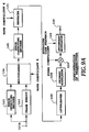
- Figs. 6A and 6B are block diagrams showing a second embodiment of a transmitter and a receiver using the variable rate transmission method in accordance with the present invention.
- the second embodiment differs from the first embodiment in that it provides the transmission rate information from the transmitter to the receiver. More specifically, it differs in the following points.
- the transmitter sends the data as shown in Figs. 7A and 7B, after interleaving, modulating and spreading it.
- the receiver despreads, demodulates and deinterleaves the received data as in the first embodiment.
- the original data sequence of one frame is recovered, and the transmission rate information, the error detecting code and the transmitted data sequence are obtained. These are fed to the error correcting decoder 154 to undergo the error correcting encoding.
- the transmission rate information contained in the recovered output of the error correcting decoder 154 is input to the transmission rate information memory 161 to be stored, and is output from the terminal 162.
- the transmitted data sequence and the error detecting code are separated by the demultiplexer 155.
- the transmitted data is fed to the error detecting encoder 156, and the terminal 159 from which it is output as the received data.
- the error detecting code is input to the error detecting code memory 157 to be stored.
- the error detecting encoder 156 carries out the same error detecting encoding as that of the transmitter to the last bit of the input data sequence. The last bit is fed from the transmission rate information memory 161. This is the very point which differs from the first embodiment. After that, the processing proceeds as in the first embodiment.
- the comparator 158 compares the error detecting code output from the error detecting encoder 156 with the contents of the error detecting code memory 157 bit by bit, and outputs the coincident signal from the terminal 160 when all the bits agree with each other. If no error occurs during the transmission, the coincident signal is output to the terminal 160, in which case, it is decided that the transmitted data in the frame output from the terminal 159, and the transmission rate information output from the terminal 162 are both received correctly.
- the decoded result of the transmission rate information is first obtained by sequentially applying the maximum likelihood decoding, and then the error correcting decoding of the transmitted data is carried out to the last bit designated by the transmission rate information.
- increasing reliability is obtained of the decoded result of the transmission rate information as the input signal stored in the decoder increases, that is, as the encoded data sequence following the transmission rate data increases, because of the characteristics of the decoder. For this reason, it is preferable that the greatest possible fixed length data sequence such as error detecting code other than the transmitted data be placed immediately after the transmission rate information without interruption.
- the following method can be used to decode the transmitted data to the last bit.
- the transmitter adds tail bits immediately after the last bit, and performs the error correcting encoding on them.
- the receiver completes the error correcting decoding with the tail bits.
- the transmitter can insert the tail bits after the transmission rate information to be transmitted, and the receiver can once complete decoding at the tail bits, and then restart the decoding of the transmitted data to the last bit.
- processings such as deinterleaving, error correcting decoding and error detecting encoding are carried out successively after writing the input data sequence of one frame into the frame memory 153A of the deinterleaver 153. Accordingly, the transmitted data sequence is delayed by an amount of one frame interval involved in the deinterleaving plus the processing time.
- the transmitter places the transmission rate information associated with the current frame at the initial position of the preceding frame, which transmission rate information is stored in the transmission rate information memory 113.
- the receiver obtains the last bit of the transmitted data of the current frame on the basis of the transmission rate information in the preceding frame stored in the transmission rate information memory 161.
- Figs. 8A and 8B show the data sequence output from the multiplexer 104 of the transmitter in this case.
- the receiver can obtain the number of bits of the effective data of the current frame before deinterleaving it. This makes it possible to eliminate the frame delay involved in the deinterleaving. As a result, the power of the received signal can be measured precisely during the transmission of the current effective data. This is required to achieve the transmission power control, in which the power of the received signal must be measured with minimum delay time to be fed back to the transmitting side.
- a dummy frame is required to send the transmission rate information of the first frame at the beginning of the successive data transmission.
- the receiver performs the reencoding and coincident detection of the error detecting code to confirm the effectiveness of the transmitted data for each frame. Therefore, even if the received transmission rate information (that is, information representative of the number of transmitted bits in the frame) is wrong, the possibility (misdetection) of outputting transmitted data of wrong length can be reduced to a minimum. This makes possible to achieve a highly reliable, variable rate data transmission.
- the received transmission rate information that is, information representative of the number of transmitted bits in the frame
- an amount of the transmitted data per frame reduces.
- a burst transmission occurs in which short data sequence is transmitted intermittently because the frame length is fixed. If it is known in advance that the number of bits (the total bits of the error detecting code and the data sequence) per frame is equal to or less than 1/K of the maximum bits of the frame where K is a positive integer, the burst mode transmission can be avoided by sending the data sequence with its individual bits repeated K times after carrying out the error correcting encoding of the data sequence.
- the following embodiments are an example of such a data transmission.
- Figs. 9A and 9B are block diagrams showing a third embodiment of the transmitter and receiver using the variable rate transmission method in accordance with the present invention.
- This embodiment mainly differs from the first embodiment as shown in Figs. 1A and 1B in the following.
- Fig. 10(A) shows the output of the multiplexer 104.
- Such arrangement of the frame including blanks will cause burst mode transmission.
- the error detecting code and transmitted data output from the error correcting encoder 105 (Fig. 10(B)) are input to the repeater 121 which repeats each bit K times (Fig. 10(C)).
- the receiver recovers the same data sequence as the output of the error correcting encoder 105 of the transmitter through the integrator 171 and the thinning out circuit 172. After that, the same processing as that of the first embodiment is carried out, thereby resulting in the final received data sequence.
- the number K of repetition used in the receiver must be identical to that used in the transmitter. Accordingly, it is necessary to send K to the receiver before the data transmission.
- This embodiment can achieve the variable rate transmission without the burst mode transmission even if the data transmission rate is substantially lower than the maximum rate.
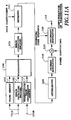
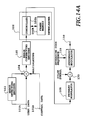
- Figs. 11A and 11B are block diagrams showing a fourth embodiment of the transmitter and receiver using the variable rate transmission method in accordance with the present invention.
- This embodiment is a combination of the second and third embodiments. Specifically, the transmission rate information memory 113 and transmission rate information memory 161 are added to the transmitter and receiver of the third embodiment, respectively.
- Fig. 12 is a diagram corresponding to Fig. 10 of the second embodiment.
- the present embodiment is characterized in that the transmission rate information is inserted immediately before the transmitted data. Since the other operation can be easily understood from the second and third embodiments, the description thereof will be omitted here.
- the individual bits are repeated K times bit by bit. This, however, is not essential.
- each predetermined number of bits (4 bits in Fig. 13) can be repeated K times (twice in Fig. 13) as a set.
- a relocater 173 is connected between the deinterleaver 153 and the integrator 171, so that the relocater 173 extracts the same bit, and the integrator 171 integrates over every K bit interval.
- the other configuration is the same as that of Fig. 9B.
- This embodiment can achieve the same effect as that of the fourth embodiment.
- the above described first to fifth embodiments do not use pilot symbols.
- the pilot symbols have a predetermined fixed pattern, and are sent intermittently with transmitted data into which the pilot symbols are inserted periodically, or sent continuously through a dedicated channel.
- a receiver extracts the pilot symbols of the known pattern, and estimates fading of transmission paths to compensate fluctuations of a received signal due to fading.
- the following embodiments relate to the variable rate transmission system including such pilot symbols.
- Figs. 14A and 14B are block diagrams showing a sixth embodiment of the transmitter and receiver using the variable rate transmission method in accordance with the present invention.
- the transmitter of Fig. 14A differs from that of Fig. 1A in the following.
- the receiver as shown in Fig. 14B differs from the receiver as shown in Fig. 1B in the following.
- the error detection circuit 144 shifts the data in each frame bit by bit, successively divides the data by predetermined data, and decides that the error detecting code is detected at the point where the data can be divided. Since the length of the error detecting code is known in advance, the last bit of the transmitted data can be found by identifying the error detecting code. Thus, the transmitted data can be extracted.
- the user data sequence applied to the input terminal 101A is divided into data with a duration of a predetermined frame period Tf.
- the error detecting encoder 102 calculates a check code (CRC bits, for example) for each frame of the user data, and supplies it to the multiplexer 104.
- the multiplexer 104 adds the control data fed from the input terminal 101B before the user data in each frame, and adds the check code from the error detecting encoder 102 at the end of the data in the frame, thereby forming one frame data.
- Fig. 16 illustrates the data output from the multiplexer 104. As shown in Fig. 16, blanks appear in the frame when the total bit number (which corresponds to the transmission rate) of the control data, user data and check code is less than the maximum bit number (maximum rate) that can be transmitted in one frame.
- the transmitted data of one frame undergoes error correcting encoding by the error correcting encoder 105, and is fed to the interleaver 106.
- the interleaver 106 reads the data of one frame which has been written in the frame memory 106B in the direction different from the writing direction as shown in Fig. 17. That is, the transmitted data of one frame written in the row direction of the interleaver 106 is read in the column direction at a predetermined rate.
- the read data undergoes phase modulation by the primary modulator 108, and is fed to the pilot symbol inserting circuit 130.
- the pilot symbol inserting circuit 130 periodically inserts the pilot symbols of a known pattern into the data supplied, thereby forming a modulated symbol sequence.
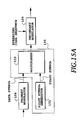
- Fig. 15A is a block diagram showing the configuration of the pilot symbol inserting circuit 130.
- the pilot symbols of a known pattern which are periodically generated by a pilot symbol generator 131, are fed to a multiplexer 132.
- the multiplexer 132 multiplexes the data fed from the primary modulator 108 and the pilot symbols, thereby generating a modulated symbol sequence.
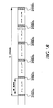
- Fig. 18 illustrates the arrangement of the modulated symbol sequence.
- a section sandwiched by the pilot symbols which are inserted periodically is called a slot.
- one slot consists of N bits and one frame consists of M slots, one frame consists of N*M bits.
- the modulated symbol sequence is fed to the secondary modulator 109.
- the secondary modulator 109 multiplies the modulated symbol sequence by a spread code sequence with a chip rate of integer (tens to several hundreds) times the symbol rate, and delivers it from the output terminal 110 to a transmission power amplifier.
- the receiver receiving the pilot symbols of the known pattern which have been periodically inserted into the data to be transmitted, estimates the phase of each symbol in the slot, and corrects the phase by using the pilot symbols. This compensates the phase of each symbol varied by the fading in the transmission. This processing is carried out by the primary demodulator 152.
- Fig. 15B is a block diagram showing the configuration of the primary demodulator 152.
- the despread signal fed from the secondary demodulator 151 is supplied to the quasi-coherent detector 181.
- the quasi-coherent detector 181 quasi-coherent detects the despread signal using the carrier of the same frequency as that of the transmitter, and supplies the detected output to a demultiplexer 182.
- the demultiplexer 182 divides the data obtained by the quasi-coherent detection into data symbols and the pilot symbols, and supplies the data symbols to a compensator 183 and the pilot symbols to a transfer function estimator 184.
- the transfer function estimator 184 estimates the transfer function of the propagation path from the pilot symbols, and supplies the transfer function to the compensator 183.
- the compensator 183 compensates the phases of the data symbols in response to the estimated transfer function, and provides the compensated output to a decision circuit 185.
- the decision circuit 185 decides the compensated data, and outputs the data symbols. Details of this processing is disclosed in the above-mentioned paper of S. Sampei.
- Fig. 3 illustrates the arrangement of the frame data in the frame memory 106B of the interleaver 106.
- the number of bits in a row of the frame memory 106B is assumed to be equal to the number of slots M constituting one frame.
- the number of bits (that is, the number of rows) in one column is assumed to be equal to the number of bits N of one slot.
- One frame data including the check code for error detection is written bit by bit into the row direction of the frame memory 106B which is represented in the form of two-dimensions.
- the writing of one frame is carried out alternately from the top and bottom of the frame memory 106B row by row.
- the numbers attached to the rows of Fig. 3 represent the writing order. Since the control data is placed at the initial position of the frame, it is written in the rows of low numbers. In other words, this important data is written at the initial and final positions of the frame in the frame memory 106B.
- the data in the frame memory 106B is read in the column direction bit by bit.
- the column numbers 1-M correspond to the slot numbers of Fig. 18.
- the receiver is provided with the deinterleaver 153 in correspondence with the interleaver 106.
- the deinterleaver 153 recovers the frame data from the slot data in the procedure opposite to that of the interleaver 106.
- the important control data can be transmitted in the portions near the pilot symbols at which errors will least occur.
- the error rate of the received data reduces as the received power increases.
- the data error rate can be reduced by controlling the transmission power in accordance with the degree of importance of the transmitted data.
- the following seventh embodiment is implemented along the lines of this.
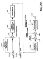
- Fig. 20 is a block diagram showing the seventh embodiment of the transmitter using the variable rate transmission method in accordance with the present invention.
- the transmitter differs from the transmitter of the sixth embodiment shown in Fig. 14A in that it is provided with a multiplier 141 next to the pilot symbol inserting circuit 130.
- the multiplier 141 multiplies the output of the pilot symbol inserting circuit 130 as shown in Fig. 19 by a predetermined power coefficient.
- the multiplier 141 multiplies a larger power coefficient as the degree of importance of the data increases. For example, the important pilot symbols and control data thereabout are multiplied by a maximum power coefficient.
- Fig. 21 is a schematic diagram illustrating the relationships between the types of data and the power coefficients. Predetermined numbers of bits are assigned to respective data in accordance with their types except for the blanks. The blanks are filled with a particular code to distinguish them from the other portions, and are multiplied by zero so that they are not transmitted. In other words, when the code representing the blanks, the power coefficient is placed zero so that their transmission is suppressed.
- the multiplier 141 of the power coefficient is inserted before the secondary modulator 109, it can be placed after the secondary modulator 109.
- Fig. 21 illustrates the control behavior of the transmission power in accordance with the degree of importance of the data.
- the foregoing first embodiment describes an example which transmits the data at various rates without providing the party with the transmission rate information representing the number of bits of the data in each frame.
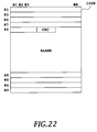
- Figs. 22 and 23 show another embodiment which does not send the transmission rate information to the receiver.
- the transmitter of this embodiment is similar to that of the seventh embodiment as shown in Fig. 20.
- Fig. 22 illustrates the transmitted bit sequence written in the frame memory of the interleaver 106 of the transmitter when the transmission rate is less than the maximum transmission rate of the transmitter.
- the error detecting code (check code) is added to the end of the transmitted data in each frame, and a blank follows that.
- the transmitted data in the frame memory 106B is read column by column at a fixed rate, and is sequentially mapped to each slot to be sent.
- the space in which the transmitted data is absent corresponds to the blank in each slot.
- the primary modulator 108 does not modulate the blanks.
- the transmitted data of the variable bit number is transmitted in a fixed frame interval, at a constant transmission rate.
- Fig. 23 shows the major portion of the receiver for receiving the data thus transmitted.
- the receiver recovers the data of each frame by the deinterleaver 153 in the opposite procedure as that of the interleaver 106 in the transmitter.
- the procedure is the same as that of the first embodiment.
- the data of one frame is fed to the error detection circuit 144 connected to the output of the interleaver 106.
- the error detection circuit 144 detects the last bit of the transmitted data in the manner as described before. More specifically, the error detection circuit 144, shifting the data in the frame bit by bit, successively divides the data by the predetermined data, and decides that the error detecting code is received and the correct transmitted data is obtained at the point at which the data can be divided.
- the transmitted original data is obtained when the received data is output at that point.
- Transmitting and receiving in this way eliminates the need to send each time the transmission rate information representing the amount of data in each frame.
- the receiver can recover the data correctly even if the amount (apparent transmission rate) of the transmitted data in each frame varies. This is because even if the transmitted data is absent, the receiver can recognize this because of the fixed frame period.
- variable rate transmission is implemented in which the apparent transmission rate (actually the bit number of data) can vary from frame to frame, even if the transmission rate information is not sent. It is necessary for the conventional variable rate transmission which does not send the transmission rate information in advance, to predetermine at intervals the values taken by the transmission rate, and this limits the number of transmission rates that can be handled. In contrast, this embodiment can achieve the transmission at any desired rates.
- a decision that no error has occurred can be made at a wrong position if an error takes place in the transmission.
- only a part of the transmitted data may be output as the effective data, or the transmitted data plus superfluous random data may be output as the effective data.
- the number of bits of the transmitted data can be set at intervals, and this will make it possible to reduce the erroneous output of the data because the error detecting points are spaced apart.
- This embodiment corresponds to the third embodiment, which avoids the burst mode transmission involved in the intermittent transmission of short data. If the transmission rate is equal to or less than 1/K of the maximum rate allowed by a single transmitting channel, the transmitted data undergoes the error correcting encoding, and each bit of the encoded data is repeated K times to form the frame data to be transmitted. The repetition number K is sent to the receiver at the beginning of the transmission.
- Fig. 24 shows the configuration of the transmitter. This embodiment differs from the transmitter of the seventh embodiment in the following.
- the data transmitted by this transmitter is demodulated by a receiver similar to that as shown in Fig. 9B to recover the transmitted data.
- the burst mode transmission can be avoided.
- the eighth embodiment can be used in combination with the ninth embodiment. In this case, if the repetition rate K has been sent to the receiver at the beginning of communications, the receiver can recover the transmitted data in accordance with the error detecting information even if the transmission rate varies frame by frame. Thus, excessive burst mode transmission can be avoided.
- a high speed data transmission requires to send data of more than N*M bits per frame. This will be handled by using a plurality of channels to carry out the parallel transmission of the data.
- the tenth embodiment is provided for achieving such a high speed transmission.
- Fig. 26 shows the tenth embodiment of the transmitter using the variable rate transmission method in accordance with the present invention
- Fig. 27 illustrates the frame arrangement to be transmitted.
- Figs. 26 and 27 show a case in which three frames are transmitted simultaneously (3 channels). A higher speed data transmission will demand more channels. The receiver is informed of the channel numbers used for the high speed transmission preceding the start of the transmission. The capacity of the frame memory of the interleaver 106 must be reserved at least twice that for storing the entire frames simultaneously transmitted. In addition, the frame memory must be accessible from a plurality of channels at the same time. Phase controllers 146b and 146c will be described in the next eleventh embodiment because this tenth embodiment describes the case in which the phase control is not performed.
- the interleaver 106 successively writes the data to be transmitted into the frame memory at a high speed to form a plurality of transmitted frames. Since the control data is placed at the initial position of each frame, it is written in the side-a of the frame memory. When the side-a of the frame memory fills up, the data is written into the side-b of the frame memory. When the side-b of the frame memory fills up, the data is written into the side-c of the frame memory. The writing to the frame memory is performed at a speed higher than a normal transmission rate (three or more times the normal rate in this case).
- Reading the plurality of frames simultaneously from this frame memory is carried out at the rate equal to the normal transmission rate.
- the writing to and reading from each of the sides of the frame memory is performed as in the sixth embodiment.
- the data associated with the side-a to side-c undergo the primary modulation by primary modulators 108a - 108c, are spread by secondary modulators 109a - 109c using different spreading code sequences, and are summed up by an adder 148 to be transmitted.
- the insertion of the pilot symbols is performed only in the channel-a, and the receiver compensates the other channels by using the pilot symbols of the channel-a. Thus, it is enough that only the channel-a inserts the pilot symbols.
- the power coefficient is controlled in the same manner as that of the seventh embodiment.
- Fig. 27 illustrates the frame structure of each transmission channel when the high speed transmission is implemented by the simultaneous transmission using a plurality of channels. As shown in this figure, he control data and the pilot symbols are sent through one channel even if a plurality of transmission channels are used. The other channels do not transmit the portions corresponding to the pilot symbols and the control data. This makes it possible to reduce the interference power to other users.
- the receiver To receive the data transmitted by the plurality of channels, the receiver must comprise the same number of receiving channels.
- the receiver using the pilot symbols transmitted through one of the channels, compensates the received signals of the other channels.
- the control data of one of the channels is also used to control the other channels.
- the deinterleaver corresponding to the interleaver 106 performs writing and reading in the procedure opposite to that of the transmitter.
- the frame memory of the deinterleaver of the receiver must satisfy the condition that it can write a plurality of data at the same time, and read the plurality of data which have been written at a high speed (three times the normal speed in this case).
- the high speed data transmission is implemented by assigning the transmitted data to a plurality of transmission channels, by carrying out the primary modulation of them, and by spreading them into wideband signals by using multiple spreading codes to be sent.
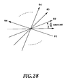
- the phase after the primary modulation of each channel is either 0 (when the transmitted data is "1") or ⁇ radian (when the transmitted data is "0").
- the spread signals also take phases of 0 or ⁇ radian. Accordingly, if N spread signals are combined without shifting their phases, the amplitude increases by a factor of N, and hence a transmission power amplifier of high peak power is required.
- phase control is carried out with the phase controllers 146b and 146c shown in Fig. 26.
- Fig. 28 illustrates the phase control when N signals are simultaneously sent.
- the peak of the transmission power can be limited as compared with the simple combining.
- phase controller 146b rotates the phase by ⁇ /3
- phase controller 146c rotates the phase by 2 ⁇ /3.
- the phase controllers 146b and 146c are inserted before the secondary modulators 109b and 109c in Fig. 26, this is not essential.
- the phase controllers 146b and 146c may be placed next to the secondary modulators 109b and 109c because it is enough that the phases are shifted of the carriers which have undergone the secondary modulation.
- the receiver since the receiver knows the phase differences of the respective channels, it must correct the phase differences with phase controllers for respective channels. After correcting the phase differences of the channels, the receiver, using the pilot symbols sent through one channel, can compensate the data of the other channels as in the tenth embodiment.
Abstract
Description
- The present invention relates to a code division multiple access (CDMA) in mobile communications systems, and more particularly to a variable rate transmission method, a transmitter and receiver using the same method, which can realize apparent variable rate transmission by transmitting data contained in frames of a fixed length at a constant transmission rate.
- In CDMA mobile communications, the output data (transmitted data) from a voice codec undergoes primary modulation, followed by secondary modulation using a pseudorandom sequence (spreading code sequence), to be spectrum-spread to a wideband signal and transmitted. The bit rate of the spreading code sequence is called a chip rate, and is tens to hundreds of times faster than the transmission rate. Generally, the primary modulation uses binary or quadrature phase shift keying, and the secondary modulation uses binary phase shift keying.
- Considering voice communications, the information amount of a transmitted voice signal is not constant, but varies from time to time. Accordingly, the transmission rate can be changed by dividing the transmitted data into frames of a fixed duration, and by transmitting data of a variable bit length in each frame, thereby achieving effective transmission of information in each frame period. This can obviate useless transmission, thereby saving power consumption of the transmitter.
- The following method is taken to transmit data of a different transmission rate in the CDMA system. First, data whose transmission rate is lower than the frame transmission rate is transmitted using a part of transmission frames (see, for example, R. Padovani, "Reverse link performance of IS-95 based cellular systems", IEEE Personal Communications, vol.1, pp.28-34, 3rd Quarter 1994). On the other hand, data whose transmission rate is higher than the frame transmission rate is divided into a plurality of transmission channels, and the divided data are spread using different spreading codes to be transmitted.
- It is necessary in this method, however, to provide a receiving side with the transmission rate information. Alternatively, when the transmission rate information is not provided, it is necessary to predetermine the values the transmission rate can take, to carry out the error detection of the received data for all the transmission rates, and to output the received data with the transmission rate at which the error is not detected as the right data.
- In this case, if an error occurs during the transmission of the transmission rate information, the effective length in the received frames cannot be decided, which makes it difficult to correctly recover the transmitted data at the receiving side even if no error has occurred during the data transmission.
- Thus, it is difficult for the conventional data transmission method to vary the transmission rate during the communications to achieve a variable rate transmission. In addition, when the data is transmitted at a rate considerably lower than a maximum transmission rate, burst transmission occurs because of blanks in the frames, during which data transmission is not carried out. Such burst-like transmission presents a problem in that it causes an EMI (Electromagnetic Interference).
- FEC (Forward Error Correction) of the transmitted data is generally used to improve the transmission quality in the case where many errors can occur during transmission as in a mobile communications environment. In this case, the transmitting side transmits transmitted data (including the transmission rate information) which has undergone error correcting encoding, and the receiving side carries out the error correcting decoding followed by extraction of the transmission rate information to decide the effective data length in each received frame. Accordingly, the transmission rate information cannot be obtained until the end of the error correcting decoding. Thus, the decoding is performed before deciding the data length to be decoded, and hence the error correction cannot fully achieve its effect.
- On the other hand, there are some data in the transmitted data that can greatly degrade the received data quality when they are corrupted. For example, control data requires transmission quality higher than voice data. Also, the voice data includes some which can greatly degrade the quality and others which cannot, depending on the voice encoding method. In other words, the transmitted data includes data of various degrees of importance.
- In view of this, a transmission method is adopted in TDMA (Time Division Multiple Access), which uses error correcting codes of different correcting power in accordance with the degree of importance of the transmitted data (see, for example, "Personal digital cellular telecommunication system RCR standard, RCR STD-27", Research & Development Center for Radio System). This method, however, lacks flexibility to transmit various data of different transmission rates.
- As described above, high speed data is divided and spread to a plurality of signals using different spreading codes, and the spread signals are combined to be transmitted. To demodulate such signals at a receiving side using coherent detection, the transmitting side must periodically inserts pilot symbols into transmitted data (see, for example, S. Sampei, "Fading Compensation for 16QAM in Land Mobile Communications", The Transactions of the Institute of Electronics, Information and Communication Engineers of Japan B-II, Vol. J72-B-II pp. 7-15, January 1989, or its revised version, S. Sampei, et al. "Rayleigh Fading Compensation for QAM in Land Mobile Radio Communications", IEEE Transactions on Vehicular Technology, VOL. 42. No. 2, MAY 1993). This method will make it necessary for the plurality of transmission channels to send the same pilot symbols when the method is applied to the signals spread with the plurality of the spreading codes. The respective channels, however, experience the same fading, and hence it is unnecessary to send the pilot symbols through the plurality of channels. Since multiple users share the same frequency band in CDMA, transmission of superfluous signals will reduce the number of users that can be accommodated in a limited frequency band because it will increase interference to other users by an amount corresponding to the transmission power necessary to send the superfluous signals.
- Furthermore, the high speed signal must be divided into a plurality of signals followed by spreading using different spreading codes and by combining of the spread signals, and the combined signal is converted into a radio frequency band followed by power amplification to be transmitted. If the plurality of spread signals are combined in the same phase, the amplitude of the combined signal will increase in proportion to the number of divided signals. This will require a high peak power liner transmission power amplifier. Such a power amplifier demanding large power consumption is unsuitable to portable telephones which require low power consumption.
- An object of the present invention is to provide a variable rate transmission method, a transmitter and a receiver using the same method, which make it possible to freely change the transmission rate without providing a receiving side with the transmission rate information of transmitted data.
- Another object of the present invention is to provide a variable rate transmission method, a transmitter and a receiver, which can achieve data protection in accordance with the degree of importance of the data constituting in the transmitted data.
- Still another object of the present invention is to provide a variable rate transmission method, a transmitter and a receiver that can flexibly send data over a wide range from low to high rate.
- In a first aspect of the present invention, there is provided a variable rate transmission method which varies an average transmission rate by transmitting each frame of a fixed duration, the frame holding transmitted data of a variable length, wherein a transmitting side comprising the steps of:
- calculating in each frame an error detecting code of the transmitted data;
- transmitting the transmitted data and the error detecting code in the each frame at a predetermined fixed transmission rate; and
- pausing transmission in a blank of each frame, the blank being a part of the frame at which the transmitted data or the error detecting code is absent, and
wherein a receiving side comprises the steps of: - receiving the each frame at the fixed transmission rate;
- detecting the error detecting code in the each frame; and
- recovering the transmitted data of the variable length in the each frame in response to a detecting result of the error detecting code.
- Here, the step of detecting the error detecting code sequentially may divide received data in the each frame by predetermined data while shifting the received data bit by bit, and may decide that the error detecting code is detected at a point at which the received data can be divided.
- The step of recovering the transmitted data may decide an end bit position of the transmitted data at a point preceding the point at which the error detecting code is detected by the number of bits of the error detecting code.
- The transmitting side may further comprise the steps of:
- periodically inserting pilot symbols of a known pattern into the each frame; and
- disposing important data of the transmitted data near the pilot symbols, and wherein the receiving side comprises the steps of:
- detecting the pilot symbols;
- compensating the transmitted data and the error detecting code which are received using the pilot symbols which are detected; andrelocating the transmitted data to its original order.
- The step of disposing the important data near the pilot symbols may comprise the steps of:
- writing the transmitted data row by row into a memory with N rows and M columns alternately from a top row and a bottom row of the memory, where N and M are positive integers;
- reading from the memory, column by column, the transmitted data which has been stored in the memory;
- inserting the pilot symbols each time the column is read, and wherein the important data is placed in advance at an initial position of the transmitted data.
- The method may be CDMA (Code Division Multiple Access), in which the transmitting side comprises the steps of performing primary modulation of the transmitted data and the error detecting code, and performing secondary modulation of a signal which has undergone the primary modulation using a spreading code sequence.
- Transmission power of the pilot symbols and the important data may be increased.
- The transmitting side may comprise the steps of:
- informing the receiving side that the transmitted data and the error detecting code are repeated K times, where K is a positive integer, when a total amount of the transmitted data and the error detecting code is equal to or less than 1/K of a maximum amount of data that can be transmitted by one frame;
- generating frames, in each of which each bit of the transmitted data and the error detecting code is repeated K times; and
- transmitting the frames which have been generated, at transmission power of 1/K of transmission power used when the each bit is not repeated,
- recovering original data from the transmitted data and the error detecting code by thinning out data using the K informed from the transmitted side.
- The transmitting side may comprise the steps of: allocating each frame of a plurality of channels with the transmitted data;
- periodically inserting pilot symbols of a known pattern into each frame of one of the plurality of channels;
- disposing important data of the transmitted data near the pilot symbols; and
- spreading the transmitted data simultaneously using different spreading code sequences assigned to the plurality of channels to transmit spread data through the each channel, and
- simultaneously receiving the plurality of channels;
- detecting pilot symbols of the one of the plurality of channels;
- compensating received signals of the plurality of channels using pilot symbols detected; and
- relocating the transmitted data received to its original order.
- Data of the plurality of channels may be transmitted with a phase of a carrier of each of the plurality of channels being shifted.
- The important data may be control data.
- The transmitting side may comprise the step of disposing the error detecting code at a fixed position in the each frame, and the receiving side comprises the steps of extracting the error detecting code placed at the fixed position in the each frame, and obtaining the number of bits of the transmitted data on the basis of the error detecting code.
- The method may be a CDMA data transmission method in which the transmitting side comprises the steps of performing primary modulation of the transmitted data and the error detecting code in the each frame, and performing secondary modulation of primary modulated data in each frame by using a spreading code sequence, to be transmitted.
- The transmitting side may comprise the step of performing error correcting encoding and interleaving of the transmitted data before the primary modulation, and wherein the receiving side comprises the steps of performing a primary demodulation of the transmitted data which is received, and performing deinterleaving and error correcting decoding of the transmitted data which have undergone the primary demodulation.
- The transmitting side may comprise the steps of:
- repeating each bit of the transmitted data and the error detecting code K times, where K is a positive integer, when a total amount of the transmitted data and the error detecting code in the each frame is equal to or less than 1/K of a maximum amount of data that can be transmitted by the each frame;
- reducing transmission power of the each frame to 1/K of transmission power used when the bit is not repeated;
- integrating over K bit interval the transmitted data and the error detecting code which have been received; and
- recovering the transmitted data by performing thinning out processing of integrated data for every K bits.
- The transmitting side may comprise the step of:
- adding to a fixed position in the each frame, transmission rate information representative of the number of bits of data in the each frame and the error detecting code, and
wherein the receiving side comprises the steps of: - obtaining an end bit position of the transmitted data in each the frame in response to the transmission rate information;
- calculating error detecting code of the transmitted data to the end position;
- comparing the calculated error detecting code with the error detecting code which has been received; and
- deciding that the transmitted data to the end bit position is correct when a compared result of the step of comparing coincides.
- Transmission method may be a CDMA data transmission method in which the transmitting side comprises the steps of performing primary modulation of the transmitted data and the error detecting code in the each frame, and performing secondary modulation of primary modulated data in each frame by using a spreading code sequence, to be transmitted.
- The transmitting side may comprise the steps of:
- performing error correcting encoding of the transmitted data, the transmission rate information and the error detecting code in the each frame before the primary modulation, and
- interleaving error correcting encoded data in the each frame, followed by supplying interleaved data to the step of performing primary modulation, and
- despreading data in the each frame which is received by using a spreading code sequence;
- performing a primary demodulation of a despread signal;
- deinterleaving transmission data which has undergone the primary demodulation;
- performing error correcting decoding of the transmission rate information and the error detecting code; and
- performing error correcting decoding of the transmitted data to its end bit in accordance with a result of the error correcting decoding of the preceding step.
- The transmitting side may comprise the step of:
- placing the transmission rate information associated with a current frame at a fixed position in a preceding frame, and
wherein the receiving side comprises the steps of: - extracting the transmission rate information received in the preceding frame; and
- deciding an end bit position of data in the current frame in response to the transmission rate information which has been extracted.
- The transmitting side may comprise the steps of:
- performing error correcting encoding of data in the each frame;
- interleaving the each frame;
- performing primary modulation of the each frame which has been interleaved; and
- performing secondary modulation of primary modulated transmission data in the each frame by using a spreading code sequence, and
wherein the receiving side comprises the steps of: - performing a primary demodulation of the transmission data which has been received;
- deinterleaving the transmission data which has undergone the primary demodulation;
- performing error correcting decoding of the transmission rate information which has been transmitted in the preceding frame, and of the error detection code in the current frame; and
- performing error correcting decoding the transmitted data to its end bit in accordance with a result of the error correcting decoding of the preceding step.
- The transmission method may comprise, when the number of bits of the transmitted data in the each frame is equal to or less than 1/K of the maximum number of bits of data that can be transmitted by the each frame, where K is a positive integer, at the transmitting side:
- repeating each bit of the transmitted data K times, where K is a positive integer; and
- reducing transmission power of the each frame to 1/K of transmission power used when the bit is not repeated,
and at the receiving side: - integrating over a K bit interval the transmitted data which has been received; and
- recovering the transmitted data by performing thinning out processing of integrated data for every K bits.
- In a second aspect of the present invention, there is provided a transmitter which varies an average transmission rate by transmitting each frame of a fixed duration, the frame holding transmitted data of a variable length, the transmitter comprising:
- means for calculating in the each frame an error detecting code of the transmitted data; and
- means for transmitting the transmitted data and the error detecting code in the each frame at a predetermined fixed transmission rate, and for pausing transmission in a blank of each frame, the blank being a part of the frame at which the transmitted data or the error detecting code is absent.
- Here, the transmitter may further comprise:
- pilot symbol inserting means for periodically inserting pilot symbols of a known pattern into the each frame;
- a memory for storing the transmitted data; and
- data relocating means for disposing near the pilot symbols important data of the transmitted data stored in the memory.
- The data relocating means may dispose the important data near the pilot symbols by writing the transmitted data into the memory row by row with a length of M bits, and by reading the stored transmitted data from the memory column by column with a length of N bits, wherein N is the number of bits of a slot sandwiched by the pilot symbols, and M is the number of the slots contained in the each frame.
- The data relocating means may write the important data into the memory alternately from a top row and a bottom row of the memory.
- The transmitter may further comprise:
- a primary modulator for modulating data in the each frame including the transmitted data, and
- a secondary modulator for performing secondary modulation that spreads data of the each frame which has undergone the primary modulation using a spreading code sequence, and
wherein the pilot symbol inserting means is connected between the primary modulator and the secondary modulator, and periodically inserts the pilot symbols between the slots. - The transmitter may further comprise a transmission power control means connected to the pilot symbol inserting means for controlling transmission power of data in the each frame in accordance with a degree of importance of the data.
- A predetermined particular code may be written in a blank in the each frame, the blank occurring when the number of bits of the transmitted data is less than the maximum number of bits of the each frame, and wherein the transmission power control means reduces transmission power of the blank to zero.
- The transmitter may further comprise a repeater preceding the memory for repeating the transmitted data and the error detecting code K times for each bit, and wherein the transmission power control means reduces transmission power of the each frame to 1/K as compared with transmission power used when the K time repeating is not performed.
- The transmitter may further comprise:
- pilot symbol inserting means for periodically inserting pilot symbols of a known pattern into the each frame;
- a memory for storing the transmitted data, the memory capable of reading multiple sets of transmitted data associated with a plurality of channels;
- data relocating means for writing data into the memory such that important data of the transmitted data stored in the memory is placed near the pilot symbols;
- a plurality of primary modulators for primary modulating the multiple sets of transmitted data read from the memory;
- a plurality of transmission power control means for controlling transmission power of the each frame
- output from the primary modulators; a plurality of secondary modulators for spreading data in the each frame output from the transmission power control means by using different spreading code sequences; and
- an adder for adding multiple signals output from the secondary modulators, and
wherein the data relocating means divides the transmitted data to be written into the memory, simultaneously reads from the memory the multiple sets of transmitted data which have been formed by the dividing, and supplies read data to the plurality of primary modulators, and the pilot symbol inserting means is connected after one of the plurality of primary modulators for periodically inserting the pilot symbols, and the plurality of transmission power control means increase transmission power while transmitting the important data. - The transmitter may further comprise a plurality of phase controllers each connected after the plurality of primary modulators for shifting phases of carriers of the secondary modulators.
- The transmitter may further comprise means for adding the error detecting code to a fixed position in the each frame.
- The transmitter may further comprise:
- means for performing error correcting encoding of data in the each frame;
- means for interleaving data which has undergone the error correcting encoding;
- means for primary modulating interleaved data; and
- means for secondary modulating primary modulated data by using a spreading code.
- The transmitter may further comprise:
- means for repeating K times each bit of data in the each frame when the number of bits of the data in the each frame is equal to or less than 1/K of the maximum number of bits that can be transmitted in one frame, where K is a positive integer; and
- transmission power control means for reducing transmission power of the each frame to 1/K in comparison with transmission power used when the K time repeating is not performed.
- The transmitter may further comprise adding means for adding, to a fixed position of the each frame, transmission rate information representative of the total number of data in the each frame, and the error detecting code.
- The transmitter may further comprise:
- means for performing error correcting encoding of the transmitted data, the transmission rate information, and the error detecting code in the each frame;
- means for interleaving data which has undergone the error correcting encoding;
- means for primary modulating interleaved data; and
- means for secondary modulating primary modulated data by using a spreading code.
- The transmitter may further comprise means for adding the transmission rate information associated with a current frame to a fixed position in a preceding frame.
- The transmitter may further comprise:
- means for repeating K times each bit of data in the each frame when the number of bits of the data in the each frame is equal to or less than 1/K of the maximum number of bits that can be transmitted in one frame, where K is a positive integer; and
- transmission power control means for reducing transmission power of the each frame to 1/K in comparison with transmission power used when the K time repeating is not performed.
- In a third aspect of the present invention, there is provided a receiver comprising:
- means for receiving, at a fixed transmission rate, frames each including transmitted data and an error correcting code;
- means for detecting error detecting code in the each frame; and
- means for recovering the transmitted data of a variable length in the each frame in response to a detection result of the error detecting code.
- Here, the means for detecting the error detecting code sequentially may divide received data in each the frame by predetermined data while shifting the received data bit by bit, and may decide that the error detecting code is detected at a point at which the received data can be divided.
- The receiver may further comprise:
- means for detecting pilot symbols of a known pattern, which are inserted into the each frame periodically to be transmitted;
- a memory for storing data in the each frame; and
- data relocating means for rearranging data written in the memory to an original order when receiving the data in the each frame, in which important data of the transmitted data is disposed near the pilot symbols.
- The data relocating means may rearrange the data in the each frame into the original order by writing the data in the each frame into the memory column by column with a length of N bits, and by reading the stored data of the each frame from the memory row by row with a length of M bits, wherein N is the number of bits of a slot sandwiched by the pilot symbols, and M is the number of the slots contained in the each frame.
- The data relocating means may carry out reading of the memory alternately from a top row and a bottom row of the memory.
- The receiver may further comprise:
- a secondary demodulator for despreading received data by using a spreading code sequence;
- a compensator for compensating the data in the each frame by using the pilot symbols; and
- a primary demodulator for demodulating the data which has been compensated by the compensator.
- The receiver may further comprise:
- means for integrating over K bit interval the data in the each frame which has been received; and
- means for recovering the transmitted data by performing thinning out of the integrated data at every K bits.
- The receiver may further comprise:
- a plurality of secondary demodulators for despreading each of multiple series of frames simultaneously transmitted through a plurality of channels;
- a compensator for compensating data in the multiple series of frames by using pilot symbols which are periodically inserted into one of multiple series of frames, and are sent through one of the plurality of channels;
- a plurality of primary demodulators for demodulating compensated data;
- a memory for storing the multiple series of data at the same time; and
- data relocating means for rearranging important data disposed near the pilot symbols to its original order by simultaneously writing the multiple series of frames in separated areas of the memory, and by reading written data in an order different from that of writing.
- The receiver may further comprise phase controllers each provided for each one of the channels for correcting phases of the multiple series of data.
- The receiver may further comprise:
- a secondary demodulator for despreading a received spread signal, and for outputting a despread signal;
- a primary demodulator for recovering data in the each frame from the despread signal;
- an error detecting code memory for storing the error detecting code placed at a fixed position in the each frame;
- means for calculating an error detecting code from the data in the each frame; and
- comparing means for comparing the calculated error detecting code with the error detecting code stored in the error detecting code memory,
wherein data is received of a variable bits in the each frame by obtaining the number of bits of the data in the each frame in response to a result of the comparison. - The receiver may further comprise:
- means for deinterleaving data output from the primary demodulator; and
- means for performing error correcting decoding of the data which has been deinterleaved.
- The receiver may further comprise:
- means for obtaining an end bit position of the transmitted data in each the frame which has been received, in response to the transmission rate information which is placed at a fixed position of the each frame to represent the number of bits of the transmitted data in the each frame;
- means for calculating error detecting code of the transmitted data to the end position;
- means for comparing the calculated error detecting code with the error detecting code which has been transmitted in the each frame; and
- means for deciding that the transmitted data to the end bit position is correct transmitted data in the each frame when a compared result coincides.
- The receiver may further comprise:
- a secondary demodulator for despreading a received spread signal, and outputs a despread signal;
- a primary demodulator for recovering data in the each frame from the despread signal;
- means for deinterleaving data output from the primary demodulator;
- means for performing error correcting decoding of the transmission rate information and the error detecting code among data output from the means for deinterleaving; and
- means for performing error correcting decoding of the transmitted data to its end bit position in response to a result of the error correcting decoding.
- The means for deciding may determine the end bit position of the transmitted data in a current frame in accordance with the transmission rate information received in a preceding frame.
- The receiver may further comprise:
- a secondary demodulator for despreading a received spread signal, and outputs a despread signal;
- a primary demodulator for recovering data in the each frame from the despread signal;
- means for deinterleaving data output from the primary demodulator;
- means for performing error correcting decoding of the transmission rate information and the error detecting code among data output from the means for deinterleaving; and
- means for performing error correcting decoding of the transmitted data to its end bit position in response to a result of the error correcting decoding of the transmission rate information received in a preceding frame.
- The receiver may further comprise, when the number of bits of data in the each frame is equal to or less than 1/K of a maximum number of bits that can be transmitted by one frame, where K is a positive integer:
- means for integrating over a K bit interval the data in the each frame which has been received; and
- means for recovering the transmitted data by performing thinning out of the integrated data at every K bits.
- In a fourth aspect of the present invention, there is provided a variable rate transmission method comprising the steps of:
- inserting pilot symbols of a known pattern into each frame periodically, and disposing important data of transmitted data near the pilot symbols, at a transmitting side, and
- detecting the pilot symbols, compensating by the detected pilot symbols the transmitted data and error detecting code which have been received, and rearranging the transmitted data which has been received to its original order.
- Here, the step of disposing the important data near the pilot symbols may comprise the steps of:
- writing the transmitted data row by row into a memory with N rows and M columns alternately from a top row and a bottom row of the memory;
- reading from the memory, column by column, the transmitted data which has been stored in the memory;
- inserting the pilot symbols each time the column is read, and wherein the important data is placed in advance at an initial position of the transmitted data.
- The method may be a CDMA data transmission method in which the transmitting side comprises the steps of performing primary modulation of the transmitted data and the error detecting code in the each frame, and performing secondary modulation of primary modulated data in each frame by using a spreading code sequence.
- The transmission power of the pilot symbols and the important data may be increased.
- According to the present invention, since the transmission rate is estimated at the receiving side in response to the error detecting information, it is unnecessary to send the transmission rate information from the transmitting side to the receiving side. This makes it possible to transmit data whose transmission rate changes frame by frame during communications.
- Alternatively, providing the receiving side with the transmission rate information can achieve higher reliability variable rate transmission.
- Furthermore, mapping the important data close to the pilot symbols in the present invention can achieve the data protection in accordance with the degree of importance of the data. This is because the data error rate is small in the neighborhood of the pilot symbols as will be described later.
- Moreover, increasing the transmission power with the degree of importance will reduce the errors of the important data in the CDMA transmission in accordance with the present invention. In addition, varying the transmission power can increase the number of users accommodated in a fixed bandwidth.
- Repeating the transmission of respective bits of the transmitted data can prevent burst transmission in the present invention even when the number of bits in a frame is much smaller than the maximum bit number of the frame, that is, even when the transmission rate of the transmitted data is much lower than the maximum transmission rate of the frame.
- Finally, according to one aspect of the present invention, the data can be transmitted at a high rate, and the interference power to other users can be reduced. This is because the CDMA system in accordance with the present invention can transmit the pilot symbols and control data through one of a plurality of channels, the other of which transmit high speed data. In addition, since the transmission signals of respective channels can combined after their phases are shifted, the peak of the transmission power can be limited, which in turn will reduce the interference power to other users.
-
- Figs. 1A and 1B are block diagrams showing a first embodiment of a transmitter and a receiver using the variable rate transmission method in accordance with the present invention;
- Figs. 2A and 2B are diagrams showing data sequences output from a
multiplexer 4 of the first embodiment, wherein Fig. 2A illustrates the data when the transmission rate is maximum, and Fig. 2B illustrates the data when the transmission rate is less than the maximum; - Fig. 3 is a schematic diagram showing a
frame memory 106B of aninterleaver 106 of Fig. 1A; - Fig. 4 is a diagram showing the structure of a frame in the data sequence output from the
frame memory 106B of Fig. 1A; - Fig. 5 is a diagram illustrating processing behavior when
frame memories - Figs. 6A and 6B are block diagrams showing a second embodiment of a transmitter and a receiver using the variable rate transmission method in accordance with the present invention;
- Figs. 7A and 7B are diagrams showing the output from the
multiplexer 4 of Fig. 6A, wherein Fig. 7A illustrates the data when the transmission rate is maximum, and Fig. 7B illustrates the data when the transmission rate is less than the maximum; - Figs. 8A and 8B are schematic diagrams illustrating data sequences output from the
multiplexer 104 of Fig. 6A when transmission rate information is held in the preceding frame; - Figs. 9A and 9B are block diagrams showing a third embodiment of a transmitter and a receiver using the variable rate transmission method in accordance with the present invention;
- Fig. 10 is a schematic diagram illustrating the operation of a
repeater 121 of Fig. 9A, wherein Fig. 10(A) illustrates the output of themultiplexer 104 of Fig. 9A, Fig. 10(B) illustrates the output of an error correcting encoder of Fig. 9A, and Fig. 10(C) illustrates the output of therepeater 121; - Figs. 11A and 11B are block diagrams showing a fourth embodiment of a transmitter and a receiver using the variable rate transmission method in accordance with the present invention;
- Fig. 12 is a schematic diagram illustrating the operation of the
repeater 121 of Fig. 11A, wherein Fig. 12(A) illustrates the output of themultiplexer 104 of Fig. 11A, Fig. 12(B) illustrates the output of the error correcting encoder of Fig. 11A, and Fig. 12(C) illustrates the output of therepeater 121; - Fig. 13 is a schematic diagram illustrating a bit repetition method of frame data in a fifth embodiment of a transmitter using the variable rate transmission method in accordance with the present invention;
- Figs. 14A and 14B are block diagrams showing a sixth embodiment of a transmitter and a receiver using the variable rate transmission method in accordance with the present invention;
- Fig. 15A is a block diagram showing the arrangement of a pilot
symbol inserting block 130 of Fig. 14A; - Fig. 15B is a block diagram showing the arrangement of a
primary demodulator 152 of Fig. 14B; - Fig. 16 is a schematic diagram illustrating the data structure output from the
multiplexer 104 of Fig. 14A; - Fig. 17 is a schematic diagram illustrating the order of writing to and reading from the
frame memory 106B of Fig. 14A; - Fig. 18 is a schematic diagram illustrating a modulated symbol sequence output from the pilot
symbol inserting block 130 of Fig. 14A; - Fig. 19 is a schematic diagram illustrating the slot structure of the sixth embodiment;
- Fig. 20 is a block diagram showing a seventh embodiment of a transmitter using the variable rate transmission method in accordance with the present invention;
- Fig. 21 is a schematic diagram illustrating power transmission control in the seventh embodiment;
- Fig. 22 is a schematic diagram illustrating an example of data stored in the
frame memory 106B in an eighth embodiment of a transmitter using the variable rate transmission method in accordance with the present invention; - Fig. 23 is a block diagram showing the major portion of the receiver of the eighth embodiment;
- Fig. 24 is a block diagram showing a ninth embodiment of a transmitter using the variable rate transmission method in accordance with the present invention;
- Fig. 25 is a block diagram showing the major portion of the receiver of the fifth embodiment;
- Fig. 26 is a block diagram showing a tenth embodiment of a transmitter using the variable rate transmission method in accordance with the present invention;
- Fig. 27 is a schematic diagram illustrating the frame structure of a plurality of channels transmitted in the tenth embodiment; and
- Fig. 28 is a diagram illustrating the phase control of a plurality of transmitted data in an eleventh embodiment of a transmitter using the variable rate transmission method in accordance with the present invention.
- The invention will now be described with reference to the accompanying drawings.
- Figs. 1A and 1B are block diagrams showing a first embodiment of a transmitter and a receiver using the variable rate transmission method in accordance with the present invention.
- Fig. 1A shows the configuration of the transmitter. In Fig. 1A, a transmitted data sequence applied to an
input terminal 101A is delivered to anerror detecting encoder 102 and aframe memory 103. Theframe memory 103 holds the data with the number of bits to be transmitted in one frame period. On the other hand, theerror detecting encoder 102 calculates the error detecting code (CRC bits, for example) of the transmitted data of one frame. Amultiplexer 104 outputs for each frame a data sequence consisting of the calculated error detecting code followed by the transmitted data. - Figs. 2A and 2B illustrate the data sequences output from the
multiplexer 104. Fig. 2A illustrates the data sequence when the transmission rate of the data is maximum, and Fig. 2B illustrates the data sequence when the transmission rate is less than the maximum. As shown in Fig. 2B, an idle time (a blank) takes place in each frame when the transmission rate is less than the maximum rate. The error detecting code is inserted at a fixed position in each frame. For example, in Figs. 2A and 2B, it is placed at the initial position of the frame. - Returning to Fig. 1A, the data sequence of one frame, into which the error detecting code is inserted, undergoes error correcting encoding through an
error correcting encoder 105, and is input to aninterleaver 106. Theinterleaver 106 includes acontroller 106A and aframe memory 106B. - Fig. 3 is a schematic diagram illustrating the
frame memory 106B of theinterleaver 106. Although theframe memory 106B has two sides, that is side-A and side-B, Fig. 3 shows only one of them. Referring to this figure, an example of interleaving will be described. Theinterleaver 106 reads the data sequence of one frame in a direction different from that of writing to theframe memory 106B. That is, theinterleaver 106 reads in the direction of columns the transmitted data which has been written in the direction of rows of theframe memory 106B. The data sequence thus interleaved is rewritten in the other side of theframe memory 106B. Incidentally, numbers #1 - #N attached to the left of theframe memory 106B indicate the order of writing the data, which will be described later in the sixth embodiment. - Fig. 4 illustrates the frame structure of the data sequence output from the
frame memory 106B. The data segments corresponding to individual rows of theframe memory 106B are called slots. Accordingly, if one side of theframe memory 106B corresponding to one frame consists of M bits/row * N rows as shown in Fig. 3, one slot consists of N bits and one frame consists of M slots, and the number of bits of one frame is N*M bits. Thus, the transmitted data undergoes error correcting encoding by theerror correcting encoder 105, followed by the interleaving by theinterleaver 106. As a result, the probability increases that the transmitted data can be corrected using the error correcting code for burst mode errors. - The
frame memories frame memory 103, and then written in the side-A of theframe memory 106B after the error correcting encoding and the interleaving. The second frame data is written in the side-B of theframe memory 103, and then written in the side-B of theframe memory 106B after the error correcting encoding and the interleaving. Using the side-A and side-B alternately makes it possible to continue the processing of a series of data sequences. - Fig. 5 illustrates the processing using the two-side frame memories. As shown in Fig. 5, the input data sequence of one frame is written in the
frame memory 103, undergoes the combined processing of the error correcting encoding and the interleaving, and then the processed data is written into theframe memory 106B. As a result, the transmitted data sequence is delayed by an amount of one frame interval plus the processing time. The data sequence output from theframe memory 106B is phase modulated by aprimary modulator 108, followed by phase modulation (spreading) through asecondary modulator 109. Thesecondary modulator 109 uses a spreading code sequence with a chip rate of integer multiple (usually from tens to hundreds of times) of the transmission rate of the transmitted data, thereby outputting the transmitted data from anoutput terminal 110. Theprimary modulator 108 does not carry out the modulation of the blank in each slot. - The transmitter, carrying out the above-mentioned processing, transmits the variable number of bits in a fixed frame period. In other words, the spread data is sent at an apparent variable transmission rate.
- Fig. 1B is a block diagram showing the receiver. The receiver despreads the spread data fed from an
input terminal 150 with asecondary demodulator 151. The despread data is detected by aprimary demodulator 152, and is fed to adeinterleaver 153. Thedeinterleaver 153 includes acontroller 153A and aframe memory 153B with two side arrangement, and operates in the reverse order of the input and output in theinterleaver 106 at the transmitter. Specifically, thecontroller 153A writes the data into theframe memory 153B column by column (slot by slot), and reads the data row by row. This procedure enables the original data sequence of one frame to be recovered, thereby producing the error detecting code and the data sequence following it. - The error detecting code and the data sequence undergo error correcting decoding through an
error correcting decoder 154, and are fed to ademultiplexer 155. Thedemultiplexer 155 separates the error detecting code and the transmitted data sequence which are placed at fixed positions in the frame. This is carried out by synchronizing frames in thedemultiplexer 155. The demultiplexed error detecting code is fed to an error detectingcode memory 157 to be held therein. On the other hand, the data sequence is output from anoutput terminal 159 as received data, and is input to anerror detecting encoder 156, as well. Theerror detecting encoder 156 performs the same error detecting encoding as that of the transmitter on the input data sequence, again. The error detecting code thus obtained is compared by acomparator 158 with the data sequence held in the error detectingcode memory 157 bit by bit of the code. Thecomparator 158 produces a coincident signal from a terminal 160 when the entire bits agrees with each other. If no error has occurred during the transmission, the coincident signal will be output at the right number of bits of the transmitted data, in which case the received data sequence in the received frame is decided correct, and is output from theoutput terminal 159. - The data transmission using the transmitter and receiver as described above makes it unnecessary to send from the transmitter to the receiver the information representing the number of bits of the frame. Accordingly, even if the number of bits in the frame (that is, the apparent transmission rate) is varied from frame to frame at the transmitting side, the receiving side can catch up with this correctly. In other words, the variable rate transmission can be achieved in which the apparent transmission rate can be varied frame by frame during the communications. Since the frame length is fixed, the receiver can always identify the frames correctly, even if frames without transmitted data are mixed.
- If an error occurs in the transmitted data, the
comparator 158 can detect (misdetect) the coincident signal at a wrong position. In this case, thedemultiplexer 155 will output either a part of the entire effective data in the frame as effective data, or data consisting of the entire effective data plus superfluous data following it. The transmitter and receiver of this embodiment, however, place the error detecting code in the fixed position in the frame, and hence, the probability of the misdetection can be reduced to a very small value by determining the number of bits of the error detecting code greater than that needed for detecting ordinary errors. In addition, limiting the number of bits allowed in one frame (for example, setting it at a multiple of two bits) will restrict the position at which the coincident signal of thecomparator 158 is obtained, and this can further reduce the probability of outputting the coincident signal at a wrong position. - Figs. 6A and 6B are block diagrams showing a second embodiment of a transmitter and a receiver using the variable rate transmission method in accordance with the present invention. The second embodiment differs from the first embodiment in that it provides the transmission rate information from the transmitter to the receiver. More specifically, it differs in the following points.
- (1) The transmitter is provided with a transmission
rate information memory 113.
The transmissionrate information memory 113 is a memory for storing the transmission rate information of the frame data held in theframe memory 103, that is, the information representing the number of bits of the frame data. The information is input to the transmissionrate information memory 113 from a terminal 101B frame by frame. Thus, the transmitter sends the data of a variable bit number with the transmission rate information in a fixed frame period. - (2) The
multiplexer 104 inserts the transmission rate information before the error detecting code.
Figs. 7A and 7B illustrate the output of themultiplexer 104. Fig. 7A illustrates the output when the transmission rate of the transmitted data is maximum, and Fig. 7B illustrates the output when the transmission rate is less than the maximum rate. In Fig. 7B, an idle time, that is, a blank including no data takes place in each frame. As shown in these figures, each frame consists of the transmission rate information, the error detecting code and the transmitted data. The frame differs from that of the first embodiment in that it is provided with the transmission rate information preceding the error detecting code. - (3) The receiver is also provided with a transmission
rate information memory 161.
The transmissionrate information memory 161 stores the transmission rate information extracted from the received data fed from theerror correcting decoder 154. - With such an arrangement, the transmitter sends the data as shown in Figs. 7A and 7B, after interleaving, modulating and spreading it.
- The receiver despreads, demodulates and deinterleaves the received data as in the first embodiment. Thus, the original data sequence of one frame is recovered, and the transmission rate information, the error detecting code and the transmitted data sequence are obtained. These are fed to the
error correcting decoder 154 to undergo the error correcting encoding. - The transmission rate information contained in the recovered output of the
error correcting decoder 154 is input to the transmissionrate information memory 161 to be stored, and is output from the terminal 162. On the other hand, the transmitted data sequence and the error detecting code are separated by thedemultiplexer 155. The transmitted data is fed to theerror detecting encoder 156, and the terminal 159 from which it is output as the received data. On the other hand, the error detecting code is input to the error detectingcode memory 157 to be stored. - The
error detecting encoder 156 carries out the same error detecting encoding as that of the transmitter to the last bit of the input data sequence. The last bit is fed from the transmissionrate information memory 161. This is the very point which differs from the first embodiment. After that, the processing proceeds as in the first embodiment. Thecomparator 158 compares the error detecting code output from theerror detecting encoder 156 with the contents of the error detectingcode memory 157 bit by bit, and outputs the coincident signal from the terminal 160 when all the bits agree with each other. If no error occurs during the transmission, the coincident signal is output to the terminal 160, in which case, it is decided that the transmitted data in the frame output from the terminal 159, and the transmission rate information output from the terminal 162 are both received correctly. - When using a convolutional code as the error correcting code, and the maximum likelihood decoding as the decoding processing in this embodiment, the decoded result of the transmission rate information is first obtained by sequentially applying the maximum likelihood decoding, and then the error correcting decoding of the transmitted data is carried out to the last bit designated by the transmission rate information. In this case, increasing reliability is obtained of the decoded result of the transmission rate information as the input signal stored in the decoder increases, that is, as the encoded data sequence following the transmission rate data increases, because of the characteristics of the decoder. For this reason, it is preferable that the greatest possible fixed length data sequence such as error detecting code other than the transmitted data be placed immediately after the transmission rate information without interruption.
- Alternatively, the following method can be used to decode the transmitted data to the last bit. The transmitter adds tail bits immediately after the last bit, and performs the error correcting encoding on them. The receiver completes the error correcting decoding with the tail bits. Alternatively, the transmitter can insert the tail bits after the transmission rate information to be transmitted, and the receiver can once complete decoding at the tail bits, and then restart the decoding of the transmitted data to the last bit.
- In the processing described above, processings such as deinterleaving, error correcting decoding and error detecting encoding are carried out successively after writing the input data sequence of one frame into the
frame memory 153A of thedeinterleaver 153. Accordingly, the transmitted data sequence is delayed by an amount of one frame interval involved in the deinterleaving plus the processing time. - To avoid such a delay, the following method can be taken. First, the transmitter places the transmission rate information associated with the current frame at the initial position of the preceding frame, which transmission rate information is stored in the transmission
rate information memory 113. On the other hand, the receiver obtains the last bit of the transmitted data of the current frame on the basis of the transmission rate information in the preceding frame stored in the transmissionrate information memory 161. - Figs. 8A and 8B show the data sequence output from the
multiplexer 104 of the transmitter in this case. When the transmission rate information is sent by the preceding frame, the receiver can obtain the number of bits of the effective data of the current frame before deinterleaving it. This makes it possible to eliminate the frame delay involved in the deinterleaving. As a result, the power of the received signal can be measured precisely during the transmission of the current effective data. This is required to achieve the transmission power control, in which the power of the received signal must be measured with minimum delay time to be fed back to the transmitting side. - To transmit the transmission rate information by the preceding frame, a dummy frame is required to send the transmission rate information of the first frame at the beginning of the successive data transmission.
- According to the transmitter and receiver described above, the receiver performs the reencoding and coincident detection of the error detecting code to confirm the effectiveness of the transmitted data for each frame. Therefore, even if the received transmission rate information (that is, information representative of the number of transmitted bits in the frame) is wrong, the possibility (misdetection) of outputting transmitted data of wrong length can be reduced to a minimum. This makes possible to achieve a highly reliable, variable rate data transmission.
- When a data sequence is transmitted at a low transmission rate by the transmitter and receiver of the above-described first and second embodiments, an amount of the transmitted data per frame reduces. In such a case, a burst transmission occurs in which short data sequence is transmitted intermittently because the frame length is fixed. If it is known in advance that the number of bits (the total bits of the error detecting code and the data sequence) per frame is equal to or less than 1/K of the maximum bits of the frame where K is a positive integer, the burst mode transmission can be avoided by sending the data sequence with its individual bits repeated K times after carrying out the error correcting encoding of the data sequence. The following embodiments are an example of such a data transmission.
- Figs. 9A and 9B are block diagrams showing a third embodiment of the transmitter and receiver using the variable rate transmission method in accordance with the present invention.
- This embodiment mainly differs from the first embodiment as shown in Figs. 1A and 1B in the following.
- (1) The transmitter is provided with a
repeater 121 connected next to theerror correcting encoder 105.
As shown in Fig. 10(C), therepeater 121 has a function to repeat each bit in the frame K times (twice in Fig. 10(C)). Thus, a new data sequence is generated in which the bits of the output data from theerror correcting encoder 105 as shown in Fig. 10(B) are each repeated K times. - (2) A
multiplier 123 for controlling the transmission power is connected between theprimary modulator 108 and thesecondary modulator 109.
The data output from therepeater 121 is interleaved by theinterleaver 106, followed by primary and secondary modulation, and the transmission thereof. Since the same bit is transmitted K times, the average transmission power of the bit increases by a factor of K as compared with the transmission power when repeating is not performed. The average transmission power is proportional to the power of interference to other users. To prevent the average transmission power increase due to the repetition of bits, the system in Fig. 9A is provided with themultiplier 123 connected after theprimary modulator 108 so that the output of theprimary modulator 108 is multiplied by the power factor of 1/K. - (3) The receiver is provided with an
integrator 171 and a thinning outcircuit 172, which are connected immediately after thedeinterleaver 153.
Theintegrator 171 obtains an integral for each continuous K symbols of the deinterleaved received data sequence. The thinning outcircuit 172 thins out the integrated output at every K symbol interval, and outputs the result. Both thecircuits - The operation of the embodiment will now be described. Fig. 10(A) shows the output of the
multiplexer 104. Such arrangement of the frame including blanks will cause burst mode transmission. To avoid this, the error detecting code and transmitted data output from the error correcting encoder 105 (Fig. 10(B)) are input to therepeater 121 which repeats each bit K times (Fig. 10(C)). The repeating coefficient K is set so that the frame is filled as much as possible (K=2 in Fig. 10). Transmitting the output of therepeater 121 can eliminate the burst mode transmission. - On the other hand, the receiver recovers the same data sequence as the output of the
error correcting encoder 105 of the transmitter through theintegrator 171 and the thinning outcircuit 172. After that, the same processing as that of the first embodiment is carried out, thereby resulting in the final received data sequence. - The number K of repetition used in the receiver must be identical to that used in the transmitter. Accordingly, it is necessary to send K to the receiver before the data transmission.
- This embodiment can achieve the variable rate transmission without the burst mode transmission even if the data transmission rate is substantially lower than the maximum rate.
- Figs. 11A and 11B are block diagrams showing a fourth embodiment of the transmitter and receiver using the variable rate transmission method in accordance with the present invention.
- This embodiment is a combination of the second and third embodiments. Specifically, the transmission
rate information memory 113 and transmissionrate information memory 161 are added to the transmitter and receiver of the third embodiment, respectively. - Fig. 12 is a diagram corresponding to Fig. 10 of the second embodiment. The present embodiment is characterized in that the transmission rate information is inserted immediately before the transmitted data. Since the other operation can be easily understood from the second and third embodiments, the description thereof will be omitted here.
- In the third and fourth embodiments described above, the individual bits are repeated K times bit by bit. This, however, is not essential. For example, as shown in Fig. 13, each predetermined number of bits (4 bits in Fig. 13) can be repeated K times (twice in Fig. 13) as a set. In the receiver as shown in Fig. 25, a
relocater 173 is connected between thedeinterleaver 153 and theintegrator 171, so that therelocater 173 extracts the same bit, and theintegrator 171 integrates over every K bit interval. The other configuration is the same as that of Fig. 9B. - This embodiment can achieve the same effect as that of the fourth embodiment.
- The above described first to fifth embodiments do not use pilot symbols. The pilot symbols have a predetermined fixed pattern, and are sent intermittently with transmitted data into which the pilot symbols are inserted periodically, or sent continuously through a dedicated channel. A receiver extracts the pilot symbols of the known pattern, and estimates fading of transmission paths to compensate fluctuations of a received signal due to fading. The following embodiments relate to the variable rate transmission system including such pilot symbols.
- Figs. 14A and 14B are block diagrams showing a sixth embodiment of the transmitter and receiver using the variable rate transmission method in accordance with the present invention.
- The transmitter of Fig. 14A differs from that of Fig. 1A in the following.
- (1) A pilot
symbol inserting circuit 130 for inserting the pilot symbols is connected between theprimary modulator 108 and thesecondary modulator 109. The pilotsymbol inserting circuit 130 will be described later with reference to Fig. 15A. - (2) The
multiplexer 104 is supplied with control data from theinput terminal 101B. The control data is important for a circuit connection or the like. - (3) The
frame memory 103 is removed, and the user data is directly applied to themultiplexer 104 from theinput terminal 101A. - On the other hand, the receiver as shown in Fig. 14B differs from the receiver as shown in Fig. 1B in the following.
- (1) The
primary demodulator 152 has a different configuration from that of Fig. 1B. This will be described later with reference to Fig. 15B. - (2) The position of the error detecting code in the frame is not specified in this embodiment, which differs from the first embodiment. Accordingly, the circuits from the
demultiplexer 155 and forward are removed, and anerror detection circuit 144 is connected to the output terminal of theerror correcting decoder 154. - The
error detection circuit 144 shifts the data in each frame bit by bit, successively divides the data by predetermined data, and decides that the error detecting code is detected at the point where the data can be divided. Since the length of the error detecting code is known in advance, the last bit of the transmitted data can be found by identifying the error detecting code. Thus, the transmitted data can be extracted. - Returning to Fig. 14A, the user data sequence applied to the
input terminal 101A is divided into data with a duration of a predetermined frame period Tf. Theerror detecting encoder 102 calculates a check code (CRC bits, for example) for each frame of the user data, and supplies it to themultiplexer 104. Themultiplexer 104 adds the control data fed from theinput terminal 101B before the user data in each frame, and adds the check code from theerror detecting encoder 102 at the end of the data in the frame, thereby forming one frame data. - Fig. 16 illustrates the data output from the
multiplexer 104. As shown in Fig. 16, blanks appear in the frame when the total bit number (which corresponds to the transmission rate) of the control data, user data and check code is less than the maximum bit number (maximum rate) that can be transmitted in one frame. - The transmitted data of one frame undergoes error correcting encoding by the
error correcting encoder 105, and is fed to theinterleaver 106. Theinterleaver 106 reads the data of one frame which has been written in theframe memory 106B in the direction different from the writing direction as shown in Fig. 17. That is, the transmitted data of one frame written in the row direction of theinterleaver 106 is read in the column direction at a predetermined rate. - The read data undergoes phase modulation by the
primary modulator 108, and is fed to the pilotsymbol inserting circuit 130. The pilotsymbol inserting circuit 130 periodically inserts the pilot symbols of a known pattern into the data supplied, thereby forming a modulated symbol sequence. - Fig. 15A is a block diagram showing the configuration of the pilot
symbol inserting circuit 130. The pilot symbols of a known pattern, which are periodically generated by a pilot symbol generator 131, are fed to amultiplexer 132. Themultiplexer 132 multiplexes the data fed from theprimary modulator 108 and the pilot symbols, thereby generating a modulated symbol sequence. - Fig. 18 illustrates the arrangement of the modulated symbol sequence. In Fig. 18, a section sandwiched by the pilot symbols which are inserted periodically is called a slot. Assuming that one slot consists of N bits and one frame consists of M slots, one frame consists of N*M bits.
- The modulated symbol sequence is fed to the
secondary modulator 109. Thesecondary modulator 109 multiplies the modulated symbol sequence by a spread code sequence with a chip rate of integer (tens to several hundreds) times the symbol rate, and delivers it from theoutput terminal 110 to a transmission power amplifier. - The receiver, receiving the pilot symbols of the known pattern which have been periodically inserted into the data to be transmitted, estimates the phase of each symbol in the slot, and corrects the phase by using the pilot symbols. This compensates the phase of each symbol varied by the fading in the transmission. This processing is carried out by the
primary demodulator 152. - Fig. 15B is a block diagram showing the configuration of the
primary demodulator 152. The despread signal fed from thesecondary demodulator 151 is supplied to thequasi-coherent detector 181. Thequasi-coherent detector 181 quasi-coherent detects the despread signal using the carrier of the same frequency as that of the transmitter, and supplies the detected output to ademultiplexer 182. Thedemultiplexer 182 divides the data obtained by the quasi-coherent detection into data symbols and the pilot symbols, and supplies the data symbols to acompensator 183 and the pilot symbols to a transfer function estimator 184. - The transfer function estimator 184 estimates the transfer function of the propagation path from the pilot symbols, and supplies the transfer function to the
compensator 183. Thecompensator 183 compensates the phases of the data symbols in response to the estimated transfer function, and provides the compensated output to adecision circuit 185. Thedecision circuit 185 decides the compensated data, and outputs the data symbols. Details of this processing is disclosed in the above-mentioned paper of S. Sampei. - In the case where the pilot symbols are thus periodically inserted into the transmitted data to achieve the coherent detection, the accuracy of the estimation of the transmission path is best near the pilot symbols. Therefore, such data that requires high quality transmission should be placed near the pilot symbols before transmission in this embodiment. Specifically, writing to and reading from the
frame memory 106B of theinterleaver 106 in Fig. 14A is controlled so that the important data which requires high quality transmission, such as the control data is placed in the neighborhood of the pilot signals. - This processing will now be described with reference to Figs. 3 and 19.
- As described before, Fig. 3 illustrates the arrangement of the frame data in the
frame memory 106B of theinterleaver 106. The number of bits in a row of theframe memory 106B is assumed to be equal to the number of slots M constituting one frame. In addition, the number of bits (that is, the number of rows) in one column is assumed to be equal to the number of bits N of one slot. One frame data including the check code for error detection is written bit by bit into the row direction of theframe memory 106B which is represented in the form of two-dimensions. The writing of one frame is carried out alternately from the top and bottom of theframe memory 106B row by row. The numbers attached to the rows of Fig. 3 represent the writing order. Since the control data is placed at the initial position of the frame, it is written in the rows of low numbers. In other words, this important data is written at the initial and final positions of the frame in theframe memory 106B. - On the other hand, the data in the
frame memory 106B is read in the column direction bit by bit. The column numbers 1-M correspond to the slot numbers of Fig. 18. By thus reading the data from theframe memory 106B, the important data (control data) will be mapped near the pilot symbols in each slot as shown in Fig. 19. In Fig. 19, a blank appears in the slot, which corresponds to the blank of each frame in Fig. 16. - The receiver is provided with the
deinterleaver 153 in correspondence with theinterleaver 106. Thedeinterleaver 153 recovers the frame data from the slot data in the procedure opposite to that of theinterleaver 106. - By thus transmitting the data, the important control data can be transmitted in the portions near the pilot symbols at which errors will least occur.
- The error rate of the received data reduces as the received power increases. Thus, the data error rate can be reduced by controlling the transmission power in accordance with the degree of importance of the transmitted data. The following seventh embodiment is implemented along the lines of this.
- Fig. 20 is a block diagram showing the seventh embodiment of the transmitter using the variable rate transmission method in accordance with the present invention. The transmitter differs from the transmitter of the sixth embodiment shown in Fig. 14A in that it is provided with a
multiplier 141 next to the pilotsymbol inserting circuit 130. Themultiplier 141 multiplies the output of the pilotsymbol inserting circuit 130 as shown in Fig. 19 by a predetermined power coefficient. Themultiplier 141 multiplies a larger power coefficient as the degree of importance of the data increases. For example, the important pilot symbols and control data thereabout are multiplied by a maximum power coefficient. - Fig. 21 is a schematic diagram illustrating the relationships between the types of data and the power coefficients. Predetermined numbers of bits are assigned to respective data in accordance with their types except for the blanks. The blanks are filled with a particular code to distinguish them from the other portions, and are multiplied by zero so that they are not transmitted. In other words, when the code representing the blanks, the power coefficient is placed zero so that their transmission is suppressed.
- Although the
multiplier 141 of the power coefficient is inserted before thesecondary modulator 109, it can be placed after thesecondary modulator 109. - Fig. 21 illustrates the control behavior of the transmission power in accordance with the degree of importance of the data. By thus controlling the transmission power, the important data are transmitted with larger transmission power, which makes it possible to reduce the error rate. In addition, since the blanks are not transmitted, extra transmission power can be suppressed. As a result, interference to other users are reduced, and the number of users accommodated in a given frequency band can be increased by that amount.
- The foregoing first embodiment describes an example which transmits the data at various rates without providing the party with the transmission rate information representing the number of bits of the data in each frame. Figs. 22 and 23 show another embodiment which does not send the transmission rate information to the receiver.
- The transmitter of this embodiment is similar to that of the seventh embodiment as shown in Fig. 20. Fig. 22 illustrates the transmitted bit sequence written in the frame memory of the
interleaver 106 of the transmitter when the transmission rate is less than the maximum transmission rate of the transmitter. The error detecting code (check code) is added to the end of the transmitted data in each frame, and a blank follows that. - In the transmission, the transmitted data in the
frame memory 106B is read column by column at a fixed rate, and is sequentially mapped to each slot to be sent. In Fig. 22, the space in which the transmitted data is absent corresponds to the blank in each slot. Theprimary modulator 108 does not modulate the blanks. As a result, the transmitted data of the variable bit number is transmitted in a fixed frame interval, at a constant transmission rate. - Fig. 23 shows the major portion of the receiver for receiving the data thus transmitted. The receiver recovers the data of each frame by the
deinterleaver 153 in the opposite procedure as that of theinterleaver 106 in the transmitter. The procedure is the same as that of the first embodiment. - The data of one frame is fed to the
error detection circuit 144 connected to the output of theinterleaver 106. Theerror detection circuit 144 detects the last bit of the transmitted data in the manner as described before. More specifically, theerror detection circuit 144, shifting the data in the frame bit by bit, successively divides the data by the predetermined data, and decides that the error detecting code is received and the correct transmitted data is obtained at the point at which the data can be divided. The transmitted original data is obtained when the received data is output at that point. - Transmitting and receiving in this way eliminates the need to send each time the transmission rate information representing the amount of data in each frame. In addition, the receiver can recover the data correctly even if the amount (apparent transmission rate) of the transmitted data in each frame varies. This is because even if the transmitted data is absent, the receiver can recognize this because of the fixed frame period.
- Thus, the variable rate transmission is implemented in which the apparent transmission rate (actually the bit number of data) can vary from frame to frame, even if the transmission rate information is not sent. It is necessary for the conventional variable rate transmission which does not send the transmission rate information in advance, to predetermine at intervals the values taken by the transmission rate, and this limits the number of transmission rates that can be handled. In contrast, this embodiment can achieve the transmission at any desired rates.
- A decision that no error has occurred can be made at a wrong position if an error takes place in the transmission. In this case, only a part of the transmitted data may be output as the effective data, or the transmitted data plus superfluous random data may be output as the effective data. Taking account of this, the number of bits of the transmitted data can be set at intervals, and this will make it possible to reduce the erroneous output of the data because the error detecting points are spaced apart.
- This embodiment corresponds to the third embodiment, which avoids the burst mode transmission involved in the intermittent transmission of short data. If the transmission rate is equal to or less than 1/K of the maximum rate allowed by a single transmitting channel, the transmitted data undergoes the error correcting encoding, and each bit of the encoded data is repeated K times to form the frame data to be transmitted. The repetition number K is sent to the receiver at the beginning of the transmission.
- Fig. 24 shows the configuration of the transmitter. This embodiment differs from the transmitter of the seventh embodiment in the following.
- (1) The
repeater 121 is connected to the output of theerror correcting encoder 105. - (2) The
multiplier 141 is connected to the output of the pilotsymbol inserting circuit 130 for multiplying the transmission power coefficient so that the transmission power is controlled to 1/K of that of the seventh embodiment as shown in Fig. 20, in which each bit of the data in the frame is not repeated. - The data transmitted by this transmitter is demodulated by a receiver similar to that as shown in Fig. 9B to recover the transmitted data.
- By thus repeating each bit K times, the burst mode transmission can be avoided. In addition, the eighth embodiment can be used in combination with the ninth embodiment. In this case, if the repetition rate K has been sent to the receiver at the beginning of communications, the receiver can recover the transmitted data in accordance with the error detecting information even if the transmission rate varies frame by frame. Thus, excessive burst mode transmission can be avoided.
- A high speed data transmission requires to send data of more than N*M bits per frame. This will be handled by using a plurality of channels to carry out the parallel transmission of the data. The tenth embodiment is provided for achieving such a high speed transmission.
- Fig. 26 shows the tenth embodiment of the transmitter using the variable rate transmission method in accordance with the present invention, and Fig. 27 illustrates the frame arrangement to be transmitted.
- Figs. 26 and 27 show a case in which three frames are transmitted simultaneously (3 channels). A higher speed data transmission will demand more channels. The receiver is informed of the channel numbers used for the high speed transmission preceding the start of the transmission. The capacity of the frame memory of the
interleaver 106 must be reserved at least twice that for storing the entire frames simultaneously transmitted. In addition, the frame memory must be accessible from a plurality of channels at the same time.Phase controllers - In Fig. 26, the
interleaver 106 successively writes the data to be transmitted into the frame memory at a high speed to form a plurality of transmitted frames. Since the control data is placed at the initial position of each frame, it is written in the side-a of the frame memory. When the side-a of the frame memory fills up, the data is written into the side-b of the frame memory. When the side-b of the frame memory fills up, the data is written into the side-c of the frame memory. The writing to the frame memory is performed at a speed higher than a normal transmission rate (three or more times the normal rate in this case). - Reading the plurality of frames simultaneously from this frame memory is carried out at the rate equal to the normal transmission rate. The writing to and reading from each of the sides of the frame memory is performed as in the sixth embodiment.
- The data associated with the side-a to side-c undergo the primary modulation by
primary modulators 108a - 108c, are spread bysecondary modulators 109a - 109c using different spreading code sequences, and are summed up by anadder 148 to be transmitted. - The insertion of the pilot symbols is performed only in the channel-a, and the receiver compensates the other channels by using the pilot symbols of the channel-a. Thus, it is enough that only the channel-a inserts the pilot symbols. The power coefficient is controlled in the same manner as that of the seventh embodiment.
- Fig. 27 illustrates the frame structure of each transmission channel when the high speed transmission is implemented by the simultaneous transmission using a plurality of channels. As shown in this figure, he control data and the pilot symbols are sent through one channel even if a plurality of transmission channels are used. The other channels do not transmit the portions corresponding to the pilot symbols and the control data. This makes it possible to reduce the interference power to other users.
- To receive the data transmitted by the plurality of channels, the receiver must comprise the same number of receiving channels. The receiver, using the pilot symbols transmitted through one of the channels, compensates the received signals of the other channels. The control data of one of the channels is also used to control the other channels. The deinterleaver corresponding to the
interleaver 106 performs writing and reading in the procedure opposite to that of the transmitter. The frame memory of the deinterleaver of the receiver must satisfy the condition that it can write a plurality of data at the same time, and read the plurality of data which have been written at a high speed (three times the normal speed in this case). - As described in the tenth embodiment, the high speed data transmission is implemented by assigning the transmitted data to a plurality of transmission channels, by carrying out the primary modulation of them, and by spreading them into wideband signals by using multiple spreading codes to be sent. Using the binary PSK, for example, the phase after the primary modulation of each channel is either 0 (when the transmitted data is "1") or π radian (when the transmitted data is "0"). When they undergo the binary PSK using the spreading code sequences, the spread signals also take phases of 0 or π radian. Accordingly, if N spread signals are combined without shifting their phases, the amplitude increases by a factor of N, and hence a transmission power amplifier of high peak power is required.
- To avoid this, the phase control is carried out with the
phase controllers - Since three channels are used in the embodiment shown in Fig. 26, the
phase controller 146b rotates the phase by π/3, and thephase controller 146c rotates the phase by 2π/3. Although thephase controllers secondary modulators phase controllers secondary modulators - On the other hand, since the receiver knows the phase differences of the respective channels, it must correct the phase differences with phase controllers for respective channels. After correcting the phase differences of the channels, the receiver, using the pilot symbols sent through one channel, can compensate the data of the other channels as in the tenth embodiment.
Claims (61)
- A variable rate transmission method which varies an average transmission rate by transmitting each frame of a fixed duration, said frame holding transmitted data of a variable length,
wherein a transmitting side comprises the steps of:calculating in each frame an error detecting code of said transmitted data;transmitting said transmitted data and said error detecting code in said each frame at a predetermined fixed transmission rate; andpausing transmission in a blank of each frame, said blank being a part of said frame at which said transmitted data or said error detecting code is absent, and
wherein a receiving side comprises the steps of:receiving said each frame at said fixed transmission rate;detecting said error detecting code in said each frame; andrecovering said transmitted data of the variable length in said each frame in response to a detecting result of said error detecting code. - The variable rate transmission method as claimed in claim 1, wherein said step of detecting said error detecting code sequentially divides received data in said each frame by predetermined data while shifting said received data bit by bit, and decides that said error detecting code is detected at a point at which said received data can be divided.
- The variable rate transmission method as claimed in claim 2, wherein said step of recovering said transmitted data decides an end bit position of said transmitted data at a point preceding the point at which said error detecting code is detected by the number of bits of said error detecting code.
- The variable rate transmission method as claimed in claim 1,
wherein said transmitting side further comprises the steps of:periodically inserting pilot symbols of a known pattern into said each frame; anddisposing important data of said transmitted data near said pilot symbols, and wherein said receiving side comprises the steps of:detecting said pilot symbols;compensating said transmitted data and said error detecting code which are received using said pilot symbols which are detected; andrelocating said transmitted data to its original order. - The variable rate transmission method as claimed in claim 4, wherein said step of disposing said important data near said pilot symbols comprises the steps of:writing said transmitted data row by row into a memory with N rows and M columns alternately from a top row and a bottom row of said memory, where N and M are positive integers;reading from said memory, column by column, said transmitted data which has been stored in said memory;inserting said pilot symbols each time said column is read, and wherein said important data is placed in advance at an initial position of said transmitted data.
- The variable rate transmission method as claimed in claim 4, wherein said method is CDMA (Code Division Multiple Access), in which said transmitting side comprises the steps of performing primary modulation of said transmitted data and said error detecting code, and performing secondary modulation of a signal which has undergone said primary modulation using a spreading code sequence.
- The variable rate transmission method as claimed in claim 6, wherein transmission power of said pilot symbols and said important data is increased.
- The variable rate transmission method as claimed in claim 1,
wherein said transmitting side comprises the steps of:informing said receiving side that said transmitted data and said error detecting code are repeated K times, where K is a positive integer, when a total amount of said transmitted data and said error detecting code is equal to or less than 1/K of a maximum amount of data that can be transmitted by one frame;generating frames, in each of which each bit of said transmitted data and said error detecting code is repeated K times; andtransmitting said frames which have been generated, at transmission power of 1/K of transmission power used when said each bit is not repeated,and wherein said receiving side comprises the step of:recovering original data from said transmitted data and said error detecting code by thinning out data using said K informed from said transmitted side. - The variable rate transmission method as claimed in claim 8,
wherein said transmitting side comprises the steps of:periodically inserting pilot symbols of a known pattern into said each frame; anddisposing important data of said transmitted data near said pilot symbols in said each frame, andwherein said receiving side comprises the steps of:detecting said pilot symbols;compensating said transmitted data and said error detecting code which have been received using said pilot symbols detected; andrelocating said transmitted data received to its original order. - The variable rate transmission method as claimed in claim 1,
wherein said transmitting side comprises the steps of:allocating each frame of a plurality of channels with said transmitted data;periodically inserting pilot symbols of a known pattern into each frame of one of said plurality of channels;disposing important data of said transmitted data near said pilot symbols; andspreading said transmitted data simultaneously using different spreading code sequences assigned to said plurality of channels to transmit spread data through said each channel, andwherein said receiving side comprises the steps of:simultaneously receiving said plurality of channels;detecting pilot symbols of said one of said plurality of channels;compensating received signals of said plurality of channels using pilot symbols detected; andrelocating said transmitted data received to its original order. - The variable rate transmission method as claimed in claim 10, wherein data of said plurality of channels are transmitted with a phase of a carrier of each of said plurality of channels being shifted.
- The variable rate transmission method as claimed in any one of claims 1-7, 9 and 11, wherein said important data is control data.
- The variable rate transmission method as claimed in claim 1, wherein said transmitting side comprises the step of disposing said error detecting code at a fixed position in said each frame, and said receiving side comprises the steps of extracting said error detecting code placed at said fixed position in said each frame, and obtaining the number of bits of said transmitted data on the basis of said error detecting code.
- The variable rate transmission method as claimed in claim 13, wherein said method is a CDMA data transmission method in which said transmitting side comprises the steps of performing primary modulation of said transmitted data and said error detecting code in said each frame, and performing secondary modulation of primary modulated data in each frame by using a spreading code sequence, to be transmitted.
- The variable rate transmission method as claimed in claim 14, wherein said transmitting side comprises the step of performing error correcting encoding and interleaving of said transmitted data before said primary modulation, and wherein said receiving side comprises the steps of performing a primary demodulation of said transmitted data which is received, and performing deinterleaving and error correcting decoding of said transmitted data which have undergone said primary demodulation.
- The variable rate transmission method as claimed in claim 13,
wherein said transmitting side comprises the steps of:repeating each bit of said transmitted data and said error detecting code K times, where K is a positive integer, when a total amount of said transmitted data and said error detecting code in said each frame is equal to or less than 1/K of a maximum amount of data that can be transmitted by said each frame;reducing transmission power of said each frame to 1/K of transmission power used when said bit is not repeated;and wherein said receiving side comprises the step of:integrating over K bit interval said transmitted data and said error detecting code which have been received; andrecovering said transmitted data by performing thinning out processing of integrated data for every K bits. - The variable rate transmission method as claimed in claim 1,
wherein said transmitting side comprises the step of:adding to a fixed position in said each frame, transmission rate information representative of the number of bits of data in said each frame and said error detecting code, andwherein said receiving side comprises the steps of:obtaining an end bit position of said transmitted data in each said frame in response to said transmission rate information;calculating error detecting code of said transmitted data to said end position;comparing said calculated error detecting code with said error detecting code which has been received; anddeciding that said transmitted data to said end bit position is correct when a compared result of the step of comparing coincides. - The variable rate transmission method as claimed in claim 17, wherein transmission method is a CDMA data transmission method in which said transmitting side comprises the steps of performing primary modulation of said transmitted data and said error detecting code in said each frame, and performing secondary modulation of primary modulated data in each frame by using a spreading code sequence, to be transmitted.
- The variable rate transmission method as claimed in claim 18,
wherein said transmitting side comprises the steps of:performing error correcting encoding of said transmitted data, said transmission rate information and said error detecting code in said each frame before said primary modulation, andinterleaving error correcting encoded data in said each frame, followed by supplying interleaved data to said step of performing primary modulation, andwherein said receiving side comprises the steps of:despreading data in said each frame which is received by using a spreading code sequence;performing a primary demodulation of a despread signal;deinterleaving transmission data which has undergone said primary demodulation;performing error correcting decoding of said transmission rate information and said error detecting code; andperforming error correcting decoding of said transmitted data to its end bit in accordance with a result of said error correcting decoding of the preceding step. - The variable rate transmission method as claimed in claim 17,
wherein said transmitting side comprises the step of:placing said transmission rate information associated with a current frame at a fixed position in a preceding frame, andwherein said receiving side comprises the steps of:extracting said transmission rate information received in said preceding frame; anddeciding an end bit position of data in said current frame in response to said transmission rate information which has been extracted. - The variable rate transmission method as claimed in claim 20,
wherein said transmitting side comprises the steps of:performing error correcting encoding of data in said each frame;interleaving said each frame;performing primary modulation of said each frame which has been interleaved; andperforming secondary modulation of primary modulated transmission data in said each frame by using a spreading code sequence, andwherein said receiving side comprises the steps of:performing a primary demodulation of said transmission data which has been received;deinterleaving said transmission data which has undergone said primary demodulation;performing error correcting decoding of said transmission rate information which has been transmitted in said preceding frame, and of said error detection code in said current frame; andperforming error correcting decoding said transmitted data to its end bit in accordance with a result of said error correcting decoding of the preceding step. - The variable rate transmission method as claimed in any one of claims 17-21, wherein said transmission method comprises, when the number of bits of said transmitted data in said each frame is equal to or less than 1/K of the maximum number of bits of data that can be transmitted by said each frame, where K is a positive integer,
at said transmitting side:repeating each bit of said transmitted data K times, where K is a positive integer; andreducing transmission power of said each frame to 1/K of transmission power used when said bit is not repeated,and at said receiving side:integrating over a K bit interval said transmitted data which has been received; andrecovering said transmitted data by performing thinning out processing of integrated data for every K bits. - A transmitter which varies an average transmission rate by transmitting each frame of a fixed duration, said frame holding transmitted data of a variable length, said transmitter comprising:means for calculating in said each frame an error detecting code of said transmitted data; andmeans for transmitting said transmitted data and said error detecting code in said each frame at a predetermined fixed transmission rate, and for pausing transmission in a blank of each frame, said blank being a part of said frame at which said transmitted data or said error detecting code is absent.
- The transmitter as claimed in claim 23, further comprising:pilot symbol inserting means for periodically inserting pilot symbols of a known pattern into said each frame;a memory for storing said transmitted data; anddata relocating means for disposing near said pilot symbols important data of said transmitted data stored in said memory.
- The transmitter as claimed in claim 24, wherein said data relocating means disposes said important data near said pilot symbols by writing said transmitted data into said memory row by row with a length of M bits, and by reading said stored transmitted data from said memory column by column with a length of N bits, wherein N is the number of bits of a slot sandwiched by said pilot symbols, and M is the number of said slots contained in said each frame.
- The transmitter as claimed in claim 25, wherein said data relocating means writes said important data into said memory alternately from a top row and a bottom row of said memory.
- The transmitter as claimed in any one of claims 24-26, further comprising:a primary modulator for modulating data in said each frame including said transmitted data, anda secondary modulator for performing secondary modulation that spreads data of said each frame which has undergone said primary modulation using a spreading code sequence, and
wherein said pilot symbol inserting means is connected between said primary modulator and said secondary modulator, and periodically inserts said pilot symbols between said slots. - The transmitter as claimed in claim 26, further comprising a transmission power control means connected to said pilot symbol inserting means for controlling transmission power of data in said each frame in accordance with a degree of importance of said data.
- The transmitter as claimed in claim 28, wherein a predetermined particular code is written in a blank in said each frame, said blank occurring when the number of bits of said transmitted data is less than the maximum number of bits of said each frame, and wherein said transmission power control means reduces transmission power of said blank to zero.
- The transmitter as claimed in claim 29, further comprising a repeater preceding said memory for repeating said transmitted data and said error detecting code K times for each bit, and wherein said transmission power control means reduces transmission power of said each frame to 1/K as compared with transmission power used when said K time repeating is not performed.
- The transmitter as claimed in claim 23, further comprising:pilot symbol inserting means for periodically inserting pilot symbols of a known pattern into said each frame;a memory for storing said transmitted data, said memory capable of reading multiple sets of transmitted data associated with a plurality of channels;data relocating means for writing data into said memory such that important data of said transmitted data stored in said memory is placed near said pilot symbols;a plurality of primary modulators for primary modulating said multiple sets of transmitted data read from said memory;a plurality of transmission power control means for controlling transmission power of said each frame output from said primary modulators;a plurality of secondary modulators for spreading data in said each frame output from said transmission power control means by using different spreading code sequences; andan adder for adding multiple signals output from said secondary modulators, and
wherein said data relocating means divides said transmitted data to be written into said memory, simultaneously reads from said memory said multiple sets of transmitted data which have been formed by the dividing, and supplies read data to said plurality of primary modulators, and said pilot symbol inserting means is connected after one of said plurality of primary modulators for periodically inserting said pilot symbols, and said plurality of transmission power control means increase transmission power while transmitting said important data. - The transmitter as claimed in claim 31, further comprising a plurality of phase controllers each connected after said plurality of primary modulators for shifting phases of carriers of said secondary modulators.
- The transmitter as claimed in claim 23, further comprising means for adding said error detecting code to a fixed position in said each frame.
- The transmitter as claimed in claim 33, further comprising:means for performing error correcting encoding of data in said each frame;means for interleaving data which has undergone said error correcting encoding;means for primary modulating interleaved data; andmeans for secondary modulating primary modulated data by using a spreading code.
- The transmitter as claimed in claim 33 or 34, further comprising:means for repeating K times each bit of data in said each frame when the number of bits of said data in said each frame is equal to or less than 1/K of the maximum number of bits that can be transmitted in one frame, where K is a positive integer; andtransmission power control means for reducing transmission power of said each frame to 1/K in comparison with transmission power used when said K time repeating is not performed.
- The transmitter as claimed in claim 23, further comprising adding means for adding, to a fixed position of said each frame, transmission rate information representative of the total number of data in said each frame, and said error detecting code.
- The transmitter as claimed in claim 36, further comprising:means for performing error correcting encoding of said transmitted data, said transmission rate information, and said error detecting code in said each frame;means for interleaving data which has undergone said error correcting encoding;means for primary modulating interleaved data; andmeans for secondary modulating primary modulated data by using a spreading code.
- The transmitter as claimed in claim 36, further comprising means for adding said transmission rate information associated with a current frame to a fixed position in a preceding frame.
- The transmitter as claimed in claim 38, further comprising:means for performing error correcting encoding of said transmitted data, said transmission rate information, and said error detecting code in said each frame;means for interleaving data which has undergone said error correcting encoding;means for primary modulating interleaved data; andmeans for secondary modulating primary modulated data by using a spreading code.
- The transmitter as claimed in any one of claims 36-39, further comprising:means for repeating K times each bit of data in said each frame when the number of bits of said data in said each frame is equal to or less than 1/K of the maximum number of bits that can be transmitted in one frame, where K is a positive integer; andtransmission power control means for reducing transmission power of said each frame to 1/K in comparison with transmission power used when said K time repeating is not performed.
- A receiver comprising:means for receiving, at a fixed transmission rate, frames each including transmitted data and an error correcting code;means for detecting error detecting code in said each frame; andmeans for recovering said transmitted data of a variable length in said each frame in response to a detection result of said error detecting code.
- The receiver as claimed in claim 41, wherein means for detecting said error detecting code sequentially divides received data in each said frame by predetermined data while shifting said received data bit by bit, and decides that said error detecting code is detected at a point at which said received data can be divided.
- The receiver as claimed in claim 41, further comprising:means for detecting pilot symbols of a known pattern, which are inserted into said each frame periodically to be transmitted;a memory for storing data in said each frame; anddata relocating means for rearranging data written in said memory to an original order when receiving said data in said each frame, in which important data of said transmitted data is disposed near said pilot symbols.
- The receiver as claimed in claim 43, wherein said data relocating means rearranges said data in said each frame into the original order by writing said data in said each frame into said memory column by column with a length of N bits, and by reading said stored data of said each frame from said memory row by row with a length of M bits, wherein N is the number of bits of a slot sandwiched by said pilot symbols, and M is the number of said slots contained in said each frame.
- The receiver as claimed in claim 44, wherein said data relocating means carries out reading of said memory alternately from a top row and a bottom row of said memory.
- The receiver as claimed in any one of claims 43-45, further comprising:a secondary demodulator for despreading received data by using a spreading code sequence;a compensator for compensating said data in said each frame by using said pilot symbols; anda primary demodulator for demodulating said data which has been compensated by said compensator.
- The receiver as claimed in claim 46, further comprising:means for integrating over K bit interval said data in said each frame which has been received; andmeans for recovering said transmitted data by performing thinning out of the integrated data at every K bits.
- The receiver as claimed in claim 41, further comprising:a plurality of secondary demodulators for despreading each of multiple series of frames simultaneously transmitted through a plurality of channels;a compensator for compensating data in said multiple series of frames by using pilot symbols which are periodically inserted into one of multiple series of frames, and are sent through one of said plurality of channels;a plurality of primary demodulators for demodulating compensated data;a memory for storing said multiple series of data at the same time; anddata relocating means for rearranging important data disposed near said pilot symbols to its original order by simultaneously writing said multiple series of frames in separated areas of said memory, and by reading written data in an order different from that of writing.
- The receiver as claimed in claim 48, further comprising phase controllers each provided for each one of said channels for correcting phases of said multiple series of data.
- The receiver as claimed in claim 41, further comprising:a secondary demodulator for despreading a received spread signal, and for outputting a despread signal;a primary demodulator for recovering data in said each frame from said despread signal;an error detecting code memory for storing said error detecting code placed at a fixed position in said each frame;means for calculating an error detecting code from said data in said each frame; andcomparing means for comparing said calculated error detecting code with said error detecting code stored in said error detecting code memory,
wherein data is received of a variable bits in said each frame by obtaining the number of bits of said data in said each frame in response to a result of the comparison. - The receiver as claimed in claim 50, further comprising:means for deinterleaving data output from said primary demodulator; andmeans for performing error correcting decoding of the data which has been deinterleaved.
- The receiver as claimed in any one of claims 50 or 51, further comprising:means for integrating over a K bit interval said data in said each frame which has been received; andmeans for recovering said transmitted data by performing thinning out of the integrated data at every K bits.
- The receiver as claimed in claim 41, further comprising:means for obtaining an end bit position of said transmitted data in each said frame which has been received, in response to said transmission rate information which is placed at a fixed position of said each frame to represent the number of bits of said transmitted data in said each frame;means for calculating error detecting code of said transmitted data to said end position;means for comparing the calculated error detecting code with said error detecting code which has been transmitted in said each frame; andmeans for deciding that said transmitted data to said end bit position is correct transmitted data in said each frame when a compared result coincides.
- The receiver as claimed in claim 53, further comprising:a secondary demodulator for despreading a received spread signal, and outputs a despread signal;a primary demodulator for recovering data in said each frame from said despread signal;means for deinterleaving data output from said primary demodulator;means for performing error correcting decoding of said transmission rate information and said error detecting code among data output from said means for deinterleaving; andmeans for performing error correcting decoding of said transmitted data to its end bit position in response to a result of said error correcting decoding.
- The receiver as claimed in claim 53, wherein said means for deciding determines the end bit position of said transmitted data in a current frame in accordance with said transmission rate information received in a preceding frame.
- The receiver as claimed in claim 55, further comprising:a secondary demodulator for despreading a received spread signal, and outputs a despread signal;a primary demodulator for recovering data in said each frame from said despread signal;means for deinterleaving data output from said primary demodulator;means for performing error correcting decoding of said transmission rate information and said error detecting code among data output from said means for deinterleaving; andmeans for performing error correcting decoding of said transmitted data to its end bit position in response to a result of said error correcting decoding of said transmission rate information received in a preceding frame.
- The receiver as claimed in any one of claims 53-56, further comprising, when the number of bits of data in said each frame is equal to or less than 1/K of a maximum number of bits that can be transmitted by one frame, where K is a positive integer:means for integrating over a K bit interval said data in said each frame which has been received; andmeans for recovering said transmitted data by performing thinning out of the integrated data at every K bits.
- A variable rate transmission method comprising the steps of:inserting pilot symbols of a known pattern into each frame periodically, and disposing important data of transmitted data near said pilot symbols, at a transmitting side, anddetecting said pilot symbols, compensating by the detected pilot symbols said transmitted data and error detecting code which have been received, and rearranging said transmitted data which has been received to its original order.
- The variable rate transmission method as claimed in claim 58, wherein said step of disposing said important data near said pilot symbols comprises the steps of:writing said transmitted data row by row into a memory with N rows and M columns alternately from a top row and a bottom row of said memory;reading from said memory, column by column, said transmitted data which has been stored in said memory;inserting said pilot symbols each time said column is read, and wherein said important data is placed in advance at an initial position of said transmitted data.
- The variable rate transmission method as claimed in claim 58, wherein said method is a CDMA data transmission method in which said transmitting side comprises the steps of performing primary modulation of said transmitted data and said error detecting code in said each frame, and performing secondary modulation of primary modulated data in each frame by using a spreading code sequence.
- The variable rate transmission method as claimed in claim 60, wherein transmission power of said pilot symbols and said important data are increased.
Priority Applications (2)
| Application Number | Priority Date | Filing Date | Title |
|---|---|---|---|
| EP05075561A EP1545026B8 (en) | 1995-02-23 | 1996-02-23 | Variable rate transmission method, transmitter and receiver using the same |
| EP03077343A EP1357689B1 (en) | 1995-02-23 | 1996-02-23 | Variable rate transmission method and transmitter using the same |
Applications Claiming Priority (10)
| Application Number | Priority Date | Filing Date | Title |
|---|---|---|---|
| JP3570295 | 1995-02-23 | ||
| JP3570295 | 1995-02-23 | ||
| JP35702/95 | 1995-02-23 | ||
| JP14772895 | 1995-06-14 | ||
| JP147728/95 | 1995-06-14 | ||
| JP14772895 | 1995-06-14 | ||
| JP324823/95 | 1995-12-13 | ||
| JP32482395 | 1995-12-13 | ||
| JP32482395 | 1995-12-13 | ||
| PCT/JP1996/000419 WO1996026582A1 (en) | 1995-02-23 | 1996-02-23 | Variable rate transmitting method, and transmitter and receiver using it |
Related Child Applications (3)
| Application Number | Title | Priority Date | Filing Date |
|---|---|---|---|
| EP03077343A Division EP1357689B1 (en) | 1995-02-23 | 1996-02-23 | Variable rate transmission method and transmitter using the same |
| EP03077343.6 Division-Into | 2003-07-25 | ||
| EP05075561.0 Division-Into | 2005-03-08 |
Publications (4)
| Publication Number | Publication Date |
|---|---|
| EP0758168A1 true EP0758168A1 (en) | 1997-02-12 |
| EP0758168A4 EP0758168A4 (en) | 2000-08-16 |
| EP0758168B1 EP0758168B1 (en) | 2004-11-24 |
| EP0758168B2 EP0758168B2 (en) | 2010-07-07 |
Family
ID=27288845
Family Applications (3)
| Application Number | Title | Priority Date | Filing Date |
|---|---|---|---|
| EP96903224A Expired - Lifetime EP0758168B2 (en) | 1995-02-23 | 1996-02-23 | Variable rate transmitting method, and transmitter and receiver using it |
| EP03077343A Expired - Lifetime EP1357689B1 (en) | 1995-02-23 | 1996-02-23 | Variable rate transmission method and transmitter using the same |
| EP05075561A Expired - Lifetime EP1545026B8 (en) | 1995-02-23 | 1996-02-23 | Variable rate transmission method, transmitter and receiver using the same |
Family Applications After (2)
| Application Number | Title | Priority Date | Filing Date |
|---|---|---|---|
| EP03077343A Expired - Lifetime EP1357689B1 (en) | 1995-02-23 | 1996-02-23 | Variable rate transmission method and transmitter using the same |
| EP05075561A Expired - Lifetime EP1545026B8 (en) | 1995-02-23 | 1996-02-23 | Variable rate transmission method, transmitter and receiver using the same |
Country Status (7)
| Country | Link |
|---|---|
| US (1) | US5896374A (en) |
| EP (3) | EP0758168B2 (en) |
| KR (1) | KR100220344B1 (en) |
| CN (2) | CN1078412C (en) |
| CA (1) | CA2188455C (en) |
| DE (2) | DE69635289T2 (en) |
| WO (1) | WO1996026582A1 (en) |
Cited By (18)
| Publication number | Priority date | Publication date | Assignee | Title |
|---|---|---|---|---|
| WO1998059473A1 (en) * | 1997-06-21 | 1998-12-30 | Northern Telecom Limited | Channel coding and interleaving for transmissions on a multicarrier system |
| DE19736434A1 (en) * | 1997-08-21 | 1999-03-11 | Nokia Mobile Phones Ltd | Methods and devices for recognizing the position of data packets lying in a serial data reception stream |
| EP0936831A1 (en) * | 1997-07-19 | 1999-08-18 | Matsushita Electronics Corporation | Cdma mobile station and cdma transmission method |
| EP0949830A2 (en) * | 1998-04-07 | 1999-10-13 | Nec Corporation | Power control method and system using idle time in mobile communication system |
| EP1107499A1 (en) * | 1999-06-21 | 2001-06-13 | NTT DoCoMo, Inc. | Data transmission method, data transmission system, sending device and receiving device |
| DE19958425A1 (en) * | 1999-12-03 | 2001-06-13 | Siemens Ag | Data transmission in a communication system |
| EP1164739A1 (en) * | 2000-06-14 | 2001-12-19 | Commissariat à l'Energie Atomique | Method for data transmission with autosynchronised correction code, autosynchronised encoder and decoder, corresponding transmitter and receiver |
| WO2002021715A2 (en) * | 2000-09-06 | 2002-03-14 | Qualcomm Incorporated | Data buffer structure for asynchronously received physical channels in a cdma system |
| WO2002007372A3 (en) * | 2000-07-13 | 2002-04-25 | Qualcomm Inc | Maximum distance block coding scheme |
| KR100370723B1 (en) * | 1999-06-01 | 2003-02-05 | 모토로라 인코포레이티드 | Method and apparatus for mapping bits to an information burst |
| WO2003034606A1 (en) * | 2001-10-19 | 2003-04-24 | Ipwireless, Inc. | METHOD AND ARRANGEMENT FOR ASYNCHRONOUS PROCESSING OF CCTrCH DATA |
| EP1330062A1 (en) * | 2002-01-16 | 2003-07-23 | Samsung Electronics Co., Ltd. | Method and apparatus for weighted non-binary repeat coding and space-time coding |
| EP1501218A1 (en) * | 1997-04-17 | 2005-01-26 | NTT DoCoMo, Inc. | Base station apparatus of mobile communication system |
| EP1596519A2 (en) * | 1997-05-14 | 2005-11-16 | Qualcomm, Incorporated | A subsriber unit and method for use in a wireless communication system |
| EP1613013A1 (en) * | 1998-08-31 | 2006-01-04 | Qualcomm, Incorporated | Method and apparatus for reducing amplitude variations and interference in communication signals employing inserted pilot signals |
| EP2091215A1 (en) | 1998-02-18 | 2009-08-19 | Samsung Electronics Co., Ltd. | Mobile radio telephone and method for operating the same |
| EP1181783B2 (en) † | 1999-06-02 | 2009-10-28 | Nokia Corporation | A method of controlling power |
| US8213485B2 (en) | 1996-05-28 | 2012-07-03 | Qualcomm Incorporated | High rate CDMA wireless communication system using variable sized channel codes |
Families Citing this family (73)
| Publication number | Priority date | Publication date | Assignee | Title |
|---|---|---|---|---|
| JP3087886B2 (en) * | 1995-10-24 | 2000-09-11 | 株式会社エヌ・ティ・ティ・ドコモ | Retransmission control method for CDMA mobile communication |
| CN1194475C (en) * | 1996-06-24 | 2005-03-23 | Ntt移动通信网株式会社 | Data transmitting method, data transmitting system, transmitter and receiver |
| JP3666155B2 (en) * | 1996-12-26 | 2005-06-29 | ソニー株式会社 | COMMUNICATION METHOD, TRANSMISSION DEVICE, AND RECEPTION DEVICE |
| KR100330196B1 (en) * | 1997-05-16 | 2002-03-28 | 다치카와 게이지 | Method of transmitting variable-length frame, transmitter, and receiver |
| US6542481B2 (en) | 1998-06-01 | 2003-04-01 | Tantivy Communications, Inc. | Dynamic bandwidth allocation for multiple access communication using session queues |
| US6081536A (en) | 1997-06-20 | 2000-06-27 | Tantivy Communications, Inc. | Dynamic bandwidth allocation to transmit a wireless protocol across a code division multiple access (CDMA) radio link |
| JP3217307B2 (en) * | 1997-11-18 | 2001-10-09 | 沖電気工業株式会社 | Wireless transmission device |
| US6222832B1 (en) | 1998-06-01 | 2001-04-24 | Tantivy Communications, Inc. | Fast Acquisition of traffic channels for a highly variable data rate reverse link of a CDMA wireless communication system |
| US9525923B2 (en) | 1997-12-17 | 2016-12-20 | Intel Corporation | Multi-detection of heartbeat to reduce error probability |
| US7394791B2 (en) * | 1997-12-17 | 2008-07-01 | Interdigital Technology Corporation | Multi-detection of heartbeat to reduce error probability |
| ES2265179T3 (en) * | 1998-01-22 | 2007-02-01 | British Telecommunications Public Limited Company | RECEPTION OF SPECTRUM SIGNALS EXTENDED WITH NARROW BAND INTERFERENCES. |
| JP3381794B2 (en) * | 1998-02-14 | 2003-03-04 | サムスン エレクトロニクス カンパニー リミテッド | Data communication apparatus and method for mobile communication system having dedicated control channel |
| JP3981899B2 (en) * | 1998-02-26 | 2007-09-26 | ソニー株式会社 | Transmission method, transmission device, and reception device |
| JP3741858B2 (en) * | 1998-03-19 | 2006-02-01 | 富士通株式会社 | Adaptive modulation system |
| ES2184430T3 (en) * | 1998-04-17 | 2003-04-01 | Matsushita Electric Ind Co Ltd | RADIO COMMUNICATION DEVICE AND PROCEDURE THAT ALLOWS THE ADJUSTMENT OF THE TRANSMISSION SPEED. |
| US7221664B2 (en) * | 1998-06-01 | 2007-05-22 | Interdigital Technology Corporation | Transmittal of heartbeat signal at a lower level than heartbeat request |
| US8134980B2 (en) | 1998-06-01 | 2012-03-13 | Ipr Licensing, Inc. | Transmittal of heartbeat signal at a lower level than heartbeat request |
| EP0975118B1 (en) * | 1998-07-24 | 2007-05-09 | Matsushita Electric Industrial Co., Ltd. | CDMA radio communication system and method |
| US6798736B1 (en) * | 1998-09-22 | 2004-09-28 | Qualcomm Incorporated | Method and apparatus for transmitting and receiving variable rate data |
| US6785323B1 (en) * | 1999-11-22 | 2004-08-31 | Ipr Licensing, Inc. | Variable rate coding for forward link |
| US6973140B2 (en) | 1999-03-05 | 2005-12-06 | Ipr Licensing, Inc. | Maximizing data rate by adjusting codes and code rates in CDMA system |
| DE60037841T2 (en) | 1999-05-10 | 2009-05-07 | Ntt Docomo Inc. | Data multiplexing and data multiplexing and data transmission methods and data transmission means |
| KR100416996B1 (en) | 1999-05-10 | 2004-02-05 | 삼성전자주식회사 | Variable-length data transmitting and receiving apparatus in accordance with radio link protocol for a mobile telecommunication system and method thereof |
| KR100516671B1 (en) * | 1999-05-24 | 2005-09-22 | 삼성전자주식회사 | Variable-length Data Transmitting and Receiving Apparatus and Method in accordance with Radio Link Protocol for Mobile Telecommunication System |
| CA2661807C (en) * | 1999-07-08 | 2012-05-22 | Samsung Electronics Co., Ltd. | Apparatus and method for controlling a demultiplexer and a multiplexer used for rate matching in a mobile communication system |
| US6732302B1 (en) * | 1999-09-30 | 2004-05-04 | Telefonaktiebolaget Lm Ericcson (Publ) | Blind rate detection in a multiplexed transmission system |
| DE19949007C1 (en) * | 1999-10-11 | 2001-02-08 | Bosch Gmbh Robert | Signal reception method, for mobile radio station in cellular radio system ,has calculated phase correction factor used for correction of phases before comparison with threshold values for data detection |
| US7522631B1 (en) * | 1999-10-26 | 2009-04-21 | Qualcomm, Incorporated | Method and apparatus for efficient data transmission control in a wireless voice-over-data communication system |
| WO2001058044A2 (en) | 2000-02-07 | 2001-08-09 | Tantivy Communications, Inc. | Minimal maintenance link to support synchronization |
| KR100424460B1 (en) * | 2000-10-05 | 2004-03-26 | 삼성전자주식회사 | Apparatus and method for detecting transmitting rate of turbo decoder |
| US7613183B1 (en) * | 2000-10-31 | 2009-11-03 | Foundry Networks, Inc. | System and method for router data aggregation and delivery |
| US6940867B1 (en) * | 2000-11-02 | 2005-09-06 | Uniden America Corporation | System and method for transmission of digitized audio samples |
| JP3795743B2 (en) | 2000-11-17 | 2006-07-12 | 株式会社エヌ・ティ・ティ・ドコモ | Data transmission method, data transmission system, transmission device and reception device |
| US8155096B1 (en) | 2000-12-01 | 2012-04-10 | Ipr Licensing Inc. | Antenna control system and method |
| US7551663B1 (en) | 2001-02-01 | 2009-06-23 | Ipr Licensing, Inc. | Use of correlation combination to achieve channel detection |
| SG185139A1 (en) | 2001-06-13 | 2012-11-29 | Ipr Licensing Inc | Transmittal of heartbeat signal at a lower level than heartbeat request |
| JP3583388B2 (en) * | 2001-06-29 | 2004-11-04 | 松下電器産業株式会社 | Data communication device and data communication method |
| US7191384B2 (en) * | 2002-10-17 | 2007-03-13 | Qualcomm Incorporated | Method and apparatus for transmitting and receiving a block of data in a communication system |
| US8204079B2 (en) | 2002-10-28 | 2012-06-19 | Qualcomm Incorporated | Joint transmission of multiple multimedia streams |
| US7342977B2 (en) * | 2002-11-26 | 2008-03-11 | Lsi Logic Corporation | Serial data transmitter with bit doubling |
| US7523305B2 (en) | 2003-12-17 | 2009-04-21 | International Business Machines Corporation | Employing cyclic redundancy checks to provide data security |
| US7451381B2 (en) * | 2004-02-03 | 2008-11-11 | Phonex Broadband Corporation | Reliable method and system for efficiently transporting dynamic data across a network |
| WO2005088882A1 (en) | 2004-03-15 | 2005-09-22 | Nortel Netowrks Limited | Pilot design for ofdm systems with four transmit antennas |
| JP4260688B2 (en) * | 2004-06-09 | 2009-04-30 | 富士通株式会社 | Data transmission device, data transmission / reception system, data transmission device control method, and data transmission / reception system control method |
| CN100413240C (en) * | 2004-06-18 | 2008-08-20 | 财团法人工业技术研究院 | Improved circulation redundance detection method for information length detection and error detection |
| WO2005125044A1 (en) | 2004-06-22 | 2005-12-29 | Nortel Networks Limited | Closed loop mimo systems and methods |
| WO2006000091A1 (en) | 2004-06-24 | 2006-01-05 | Nortel Networks Limited | Preambles in ofdma system |
| US8014377B2 (en) | 2004-06-24 | 2011-09-06 | Nortel Networks Limited | Efficient location updates, paging and short bursts |
| US8588326B2 (en) | 2004-07-07 | 2013-11-19 | Apple Inc. | System and method for mapping symbols for MIMO transmission |
| CN101808290B (en) | 2004-10-15 | 2016-03-16 | 苹果公司 | Communication resource allocation systems and method |
| WO2006106864A1 (en) | 2005-03-30 | 2006-10-12 | Ntt Docomo, Inc. | Data transmission method, data transmission system, transmitting method, receiving method, transmitting apparatus and receiving apparatus |
| US7219292B2 (en) * | 2005-04-14 | 2007-05-15 | Industrial Technology Research Institute | Cyclic redundancy check modification for length detection of message with convolutional protection |
| US7823048B2 (en) * | 2005-05-31 | 2010-10-26 | Nokia Corporation | Buffering of data from a data stream having error correction elements |
| US20090046694A1 (en) * | 2005-11-04 | 2009-02-19 | Matsushita Electric Industrial Co., Ltd. | Radio transmission apparatus, and radio transmission method |
| JP3917633B1 (en) * | 2005-11-21 | 2007-05-23 | シャープ株式会社 | Digital demodulator, control method therefor, program for digital demodulator, recording medium storing program for digital demodulator, and digital receiver |
| JP4245602B2 (en) * | 2005-11-25 | 2009-03-25 | シャープ株式会社 | Digital demodulator, digital receiver, digital demodulator control method, digital demodulator control program, and recording medium recording the control program |
| US8300524B1 (en) | 2006-01-30 | 2012-10-30 | Doug Carson & Associates, Inc. | Authenticating a data transmission by varying a rate thereof |
| US8995411B2 (en) * | 2006-07-25 | 2015-03-31 | Broadcom Corporation | Method and system for content-aware mapping/error protection using different spatial streams |
| GB0622830D0 (en) * | 2006-11-15 | 2006-12-27 | Cambridge Silicon Radio Ltd | Transmission rate selection |
| GB0622829D0 (en) | 2006-11-15 | 2006-12-27 | Cambridge Silicon Radio Ltd | Transmission rate selection |
| JP5207756B2 (en) * | 2007-03-07 | 2013-06-12 | キヤノン株式会社 | COMMUNICATION SYSTEM, COMMUNICATION DEVICE, AND CONTROL METHOD THEREOF |
| JP4893830B2 (en) * | 2007-08-10 | 2012-03-07 | 富士通株式会社 | Mobile device and radio base station side apparatus in radio communication system |
| US8261154B2 (en) * | 2007-11-12 | 2012-09-04 | Motorola Mobility Llc | Continuous redundancy check method and apparatus |
| JP2009225343A (en) * | 2008-03-18 | 2009-10-01 | Fujitsu Ltd | Wireless communication equipment |
| CN101588188B (en) * | 2008-05-22 | 2013-01-30 | 展讯通信(上海)有限公司 | Time division duplex wireless communication device and transmitting and receiving method thereof |
| FR2937483A1 (en) * | 2008-10-17 | 2010-04-23 | Thomson Licensing | METHOD FOR RECEIVING A SIGNAL AND TRANSMITTING METHOD THEREOF |
| US8788903B2 (en) * | 2008-10-23 | 2014-07-22 | Panasonic Intellectual Property Corporation Of America | Wireless transmission device, wireless receiving device, and method for transmitting encoded data |
| JP5578480B2 (en) * | 2010-03-03 | 2014-08-27 | パナソニック インテレクチュアル プロパティ コーポレーション オブ アメリカ | Wireless communication apparatus and data rearrangement method |
| US8446292B2 (en) * | 2010-07-29 | 2013-05-21 | Baker Hughes Incorporated | Systems and methods for downhole instrument communication via power cable |
| US9100102B2 (en) | 2011-01-11 | 2015-08-04 | Texas Instruments Incorporated | Method to use a preamble with band extension in power line communications |
| JP6181464B2 (en) * | 2013-08-21 | 2017-08-16 | ホーチキ株式会社 | Wireless disaster prevention system |
| CN105531942B (en) * | 2013-10-14 | 2019-12-17 | 哈曼国际工业有限公司 | Communication method and system |
| CN105430744B (en) * | 2015-12-14 | 2020-03-24 | 广州广电计量检测股份有限公司 | Positioning method and positioning system |
Citations (5)
| Publication number | Priority date | Publication date | Assignee | Title |
|---|---|---|---|---|
| US5103459A (en) † | 1990-06-25 | 1992-04-07 | Qualcomm Incorporated | System and method for generating signal waveforms in a cdma cellular telephone system |
| US5204876A (en) * | 1991-03-13 | 1993-04-20 | Motorola, Inc. | Method and apparatus for providing high data rate traffic channels in a spread spectrum communication system |
| EP0564937A1 (en) * | 1992-04-10 | 1993-10-13 | Roke Manor Research Limited | CDMA Radio communication system with pilot signal transmission between base and handsets for channel distortion compensation |
| US5341396A (en) * | 1993-03-02 | 1994-08-23 | The Boeing Company | Multi-rate spread system |
| WO1995001032A1 (en) † | 1993-06-18 | 1995-01-05 | Qualcomm Incorporated | Method and apparatus for determining the data rate of a received signal |
Family Cites Families (14)
| Publication number | Priority date | Publication date | Assignee | Title |
|---|---|---|---|---|
| JPS62169550A (en) * | 1986-01-22 | 1987-07-25 | Hitachi Ltd | Data reception control system |
| JPS6331330A (en) * | 1986-07-25 | 1988-02-10 | Nippon Telegr & Teleph Corp <Ntt> | Transfer error detection system |
| JPH03108927A (en) * | 1989-09-22 | 1991-05-09 | Nec Corp | Frame transfer system |
| JPH03250935A (en) * | 1990-02-28 | 1991-11-08 | Victor Co Of Japan Ltd | Variable length data transmission system and its transmitter-receiver |
| JPH03261255A (en) * | 1990-03-12 | 1991-11-21 | Casio Comput Co Ltd | Data transfer system |
| US5511073A (en) * | 1990-06-25 | 1996-04-23 | Qualcomm Incorporated | Method and apparatus for the formatting of data for transmission |
| US5235614A (en) * | 1991-03-13 | 1993-08-10 | Motorola, Inc. | Method and apparatus for accommodating a variable number of communication channels in a spread spectrum communication system |
| JP2776075B2 (en) * | 1991-08-13 | 1998-07-16 | 松下電器産業株式会社 | Transmission method of variable length coded data |
| DE4210305A1 (en) * | 1992-03-30 | 1993-10-07 | Sel Alcatel Ag | Method, transmitter and receiver for information data transmission with variable traffic volume and control station for coordinating several such transmitters and receivers |
| JP3168063B2 (en) * | 1992-05-18 | 2001-05-21 | 富士通株式会社 | Spread spectrum communication apparatus and communication method therefor |
| JPH05344162A (en) * | 1992-06-09 | 1993-12-24 | Canon Inc | Data transmitter |
| US5302914A (en) * | 1992-10-20 | 1994-04-12 | At&T Bell Laboratories | Method and apparatus for reducing the peak-to-average power in multi-carrier RF communication systems |
| JPH06216963A (en) * | 1993-01-14 | 1994-08-05 | Matsushita Electric Ind Co Ltd | Data transmission and restructure method by fixed length frame |
| US5509020A (en) * | 1993-05-27 | 1996-04-16 | Sony Corporation | Viterbi decoding apparatus and methods |
-
1996
- 1996-02-23 CA CA002188455A patent/CA2188455C/en not_active Expired - Lifetime
- 1996-02-23 WO PCT/JP1996/000419 patent/WO1996026582A1/en active IP Right Grant
- 1996-02-23 DE DE69635289T patent/DE69635289T2/en not_active Expired - Lifetime
- 1996-02-23 EP EP96903224A patent/EP0758168B2/en not_active Expired - Lifetime
- 1996-02-23 CN CN96190221A patent/CN1078412C/en not_active Expired - Lifetime
- 1996-02-23 DE DE69633891T patent/DE69633891T3/en not_active Expired - Lifetime
- 1996-02-23 US US08/732,413 patent/US5896374A/en not_active Expired - Lifetime
- 1996-02-23 EP EP03077343A patent/EP1357689B1/en not_active Expired - Lifetime
- 1996-02-23 EP EP05075561A patent/EP1545026B8/en not_active Expired - Lifetime
- 1996-02-23 KR KR1019960705944A patent/KR100220344B1/en not_active IP Right Cessation
-
2001
- 2001-07-09 CN CNB011224584A patent/CN1180561C/en not_active Expired - Lifetime
Patent Citations (6)
| Publication number | Priority date | Publication date | Assignee | Title |
|---|---|---|---|---|
| US5103459A (en) † | 1990-06-25 | 1992-04-07 | Qualcomm Incorporated | System and method for generating signal waveforms in a cdma cellular telephone system |
| US5103459B1 (en) † | 1990-06-25 | 1999-07-06 | Qualcomm Inc | System and method for generating signal waveforms in a cdma cellular telephone system |
| US5204876A (en) * | 1991-03-13 | 1993-04-20 | Motorola, Inc. | Method and apparatus for providing high data rate traffic channels in a spread spectrum communication system |
| EP0564937A1 (en) * | 1992-04-10 | 1993-10-13 | Roke Manor Research Limited | CDMA Radio communication system with pilot signal transmission between base and handsets for channel distortion compensation |
| US5341396A (en) * | 1993-03-02 | 1994-08-23 | The Boeing Company | Multi-rate spread system |
| WO1995001032A1 (en) † | 1993-06-18 | 1995-01-05 | Qualcomm Incorporated | Method and apparatus for determining the data rate of a received signal |
Non-Patent Citations (4)
| Title |
|---|
| 'European digital cellular telecommunications system (Phase 2); Discontinuous Transmission (DTX) for full rate speech traffic channel' GSM 06.31 - ETS 300 580-5 VERSION 4.0.4 September 1994, pages 1 - 15 † |
| 'Mobile Station - Base Station Compatibility Standard for Dual-Mode Wideband Spread Spectrum Cellular System' TIA/EIA INTERIM STANDARD July 1993, † |
| ROBERTO PADOVANI: 'Reverse Link Performance of IS-95 Based Cellular Systems' IEEE PERSONAL COMMUNICATIONS July 1994 - September 1994, pages 28 - 34 † |
| See also references of WO9626582A1 † |
Cited By (45)
| Publication number | Priority date | Publication date | Assignee | Title |
|---|---|---|---|---|
| US8588277B2 (en) | 1996-05-28 | 2013-11-19 | Qualcomm Incorporated | High data rate CDMA wireless communication system using variable sized channel codes |
| US8213485B2 (en) | 1996-05-28 | 2012-07-03 | Qualcomm Incorporated | High rate CDMA wireless communication system using variable sized channel codes |
| US8005120B2 (en) | 1997-04-17 | 2011-08-23 | Ntt Docomo, Inc. | Base station apparatus of mobile communication system |
| US7095780B2 (en) | 1997-04-17 | 2006-08-22 | Ntt Docomo, Inc. | Base station apparatus of mobile communication system |
| US7443907B2 (en) | 1997-04-17 | 2008-10-28 | Ntt Docomo, Inc. | Base station apparatus of mobile communication system |
| EP1501218A1 (en) * | 1997-04-17 | 2005-01-26 | NTT DoCoMo, Inc. | Base station apparatus of mobile communication system |
| US7672357B2 (en) | 1997-04-17 | 2010-03-02 | Ntt Docomo, Inc. | Base station apparatus of mobile communication system |
| US7826861B2 (en) | 1997-04-17 | 2010-11-02 | Ntt Docomo, Inc. | Base station apparatus of mobile communication system |
| EP2224623A3 (en) * | 1997-04-17 | 2011-04-06 | NTT DoCoMo, Inc. | Base station apparatus of mobile communication system |
| EP1596519A2 (en) * | 1997-05-14 | 2005-11-16 | Qualcomm, Incorporated | A subsriber unit and method for use in a wireless communication system |
| EP1596519A3 (en) * | 1997-05-14 | 2006-12-20 | Qualcomm, Incorporated | A subsriber unit and method for use in a wireless communication system |
| WO1998059473A1 (en) * | 1997-06-21 | 1998-12-30 | Northern Telecom Limited | Channel coding and interleaving for transmissions on a multicarrier system |
| EP0936831A4 (en) * | 1997-07-19 | 2003-04-02 | Matsushita Electric Ind Co Ltd | Cdma mobile station and cdma transmission method |
| EP0936831A1 (en) * | 1997-07-19 | 1999-08-18 | Matsushita Electronics Corporation | Cdma mobile station and cdma transmission method |
| DE19736434C2 (en) * | 1997-08-21 | 1999-06-24 | Nokia Mobile Phones Ltd | Methods and devices for recognizing the position of data packets lying in a serial data reception stream |
| DE19736434C3 (en) * | 1997-08-21 | 2002-08-22 | Nokia Mobile Phones Ltd | Methods and devices for recognizing the position of data packets lying in a serial data reception stream |
| DE19736434A1 (en) * | 1997-08-21 | 1999-03-11 | Nokia Mobile Phones Ltd | Methods and devices for recognizing the position of data packets lying in a serial data reception stream |
| US6212660B1 (en) | 1997-08-21 | 2001-04-03 | Nokia Mobile Phones Limited | Methods and apparatuses for identification of the position of data packets which are located in a serial received data stream |
| EP2797301A1 (en) * | 1998-02-18 | 2014-10-29 | Samsung Electronics Co., Ltd | Mobile radio telephone and method for operating the same |
| EP2091215A1 (en) | 1998-02-18 | 2009-08-19 | Samsung Electronics Co., Ltd. | Mobile radio telephone and method for operating the same |
| EP0949830A3 (en) * | 1998-04-07 | 2000-11-29 | Nec Corporation | Power control method and system using idle time in mobile communication system |
| EP0949830A2 (en) * | 1998-04-07 | 1999-10-13 | Nec Corporation | Power control method and system using idle time in mobile communication system |
| EP1624708A3 (en) * | 1998-04-07 | 2012-12-12 | NEC Corporation | Mobile communication system, communication control method, and base station and mobile station to be employed in the same |
| EP1624708A2 (en) * | 1998-04-07 | 2006-02-08 | Nec Corporation | Mobile communication system, communication control method, and base station and mobile station to be employed in the same |
| EP1613013A1 (en) * | 1998-08-31 | 2006-01-04 | Qualcomm, Incorporated | Method and apparatus for reducing amplitude variations and interference in communication signals employing inserted pilot signals |
| KR100697510B1 (en) * | 1998-08-31 | 2007-03-20 | 콸콤 인코포레이티드 | Method and apparatus for reducing amplitude variations and interference in communication signals, such as in wireless communication signals employing inserted pilot symbols |
| KR100370723B1 (en) * | 1999-06-01 | 2003-02-05 | 모토로라 인코포레이티드 | Method and apparatus for mapping bits to an information burst |
| EP1181783B2 (en) † | 1999-06-02 | 2009-10-28 | Nokia Corporation | A method of controlling power |
| US7797012B1 (en) | 1999-06-02 | 2010-09-14 | Nokia Corporation | Method of controlling power |
| EP1107499A1 (en) * | 1999-06-21 | 2001-06-13 | NTT DoCoMo, Inc. | Data transmission method, data transmission system, sending device and receiving device |
| EP1107499B1 (en) * | 1999-06-21 | 2006-09-06 | NTT DoCoMo, Inc. | Data transmission method, data transmission system, sending device and receiving device |
| US7020209B1 (en) | 1999-06-21 | 2006-03-28 | Ntt Docomo, Inc. | Data transmission method, data transmission system, transmitter and receiver |
| DE19958425A1 (en) * | 1999-12-03 | 2001-06-13 | Siemens Ag | Data transmission in a communication system |
| USRE41774E1 (en) | 2000-06-14 | 2010-09-28 | Commissariat A L'energie Atomique | Data transmission process with auto-synchronized correcting code, auto-synchronized coder and decoder, corresponding transmitter and receiver |
| US7095818B2 (en) | 2000-06-14 | 2006-08-22 | Marc Laugeois | Data transmission process with auto-synchronized correcting code, auto-synchronized coder and decoder, corresponding transmitter and receiver |
| USRE43204E1 (en) | 2000-06-14 | 2012-02-21 | Xantima Llc | Data transmission process with auto-synchronized correcting code, auto-synchronized coder and decoder, corresponding to transmitter and receiver |
| FR2810479A1 (en) * | 2000-06-14 | 2001-12-21 | Commissariat Energie Atomique | DATA TRANSMISSION METHOD WITH SELF-SYNCHRONIZING CORRECTIVE CODE, SELF-SYNCHRONIZED ENCODER AND DECODER, CORRESPONDING TRANSMITTER AND RECEIVER |
| EP1164739A1 (en) * | 2000-06-14 | 2001-12-19 | Commissariat à l'Energie Atomique | Method for data transmission with autosynchronised correction code, autosynchronised encoder and decoder, corresponding transmitter and receiver |
| WO2002007372A3 (en) * | 2000-07-13 | 2002-04-25 | Qualcomm Inc | Maximum distance block coding scheme |
| WO2002021715A3 (en) * | 2000-09-06 | 2002-05-30 | Qualcomm Inc | Data buffer structure for asynchronously received physical channels in a cdma system |
| WO2002021715A2 (en) * | 2000-09-06 | 2002-03-14 | Qualcomm Incorporated | Data buffer structure for asynchronously received physical channels in a cdma system |
| WO2003034606A1 (en) * | 2001-10-19 | 2003-04-24 | Ipwireless, Inc. | METHOD AND ARRANGEMENT FOR ASYNCHRONOUS PROCESSING OF CCTrCH DATA |
| US7313118B2 (en) | 2001-10-19 | 2007-12-25 | Ipwireless, Inc. | Method and arrangement for asynchronous processing of CCTrCH data |
| EP1330062A1 (en) * | 2002-01-16 | 2003-07-23 | Samsung Electronics Co., Ltd. | Method and apparatus for weighted non-binary repeat coding and space-time coding |
| US7423996B2 (en) | 2002-01-16 | 2008-09-09 | Samsung Electronics Co., Ltd. | Method and apparatus for weighted non-binary repeat accumulate coding and space-time coding |
Also Published As
| Publication number | Publication date |
|---|---|
| EP1357689A3 (en) | 2003-11-12 |
| EP1357689B1 (en) | 2005-10-12 |
| WO1996026582A1 (en) | 1996-08-29 |
| EP1357689A2 (en) | 2003-10-29 |
| EP0758168B1 (en) | 2004-11-24 |
| CN1365208A (en) | 2002-08-21 |
| CN1078412C (en) | 2002-01-23 |
| CA2188455A1 (en) | 1996-08-29 |
| EP1545026B1 (en) | 2012-06-13 |
| KR100220344B1 (en) | 1999-09-15 |
| DE69635289D1 (en) | 2006-02-23 |
| EP0758168A4 (en) | 2000-08-16 |
| CN1148919A (en) | 1997-04-30 |
| DE69633891T2 (en) | 2006-02-09 |
| DE69633891T3 (en) | 2011-03-17 |
| EP1545026B8 (en) | 2012-07-18 |
| EP0758168B2 (en) | 2010-07-07 |
| US5896374A (en) | 1999-04-20 |
| DE69633891D1 (en) | 2004-12-30 |
| CN1180561C (en) | 2004-12-15 |
| DE69635289T2 (en) | 2006-04-27 |
| CA2188455C (en) | 2003-07-15 |
| EP1545026A1 (en) | 2005-06-22 |
Similar Documents
| Publication | Publication Date | Title |
|---|---|---|
| US5896374A (en) | Variable rate transmission method, transmitter and receiver using the same | |
| US5930230A (en) | High data rate CDMA wireless communication system | |
| EP0903019B1 (en) | Subscriber unit for a cdma wireless communication system | |
| EP2202902B1 (en) | A subscriber unit and method for use in a wireless communication system | |
| US7283559B2 (en) | Transmitting/receiving apparatus and method for packet data service in a mobile telecommunication system | |
| US5909434A (en) | Bright and burst mode signaling data transmission in an adjustable rate wireless communication system | |
| US5822359A (en) | Coherent random access channel in a spread-spectrum communication system and method | |
| EP0981914B1 (en) | Subscriber unit with plural control and data sources for cdma wireless communication system | |
| EP0985277A1 (en) | Bi-orthogonal code division multiple access system | |
| CA2614573C (en) | Variable rate transmission method, transmitter and receiver using the same | |
| JP2855172B2 (en) | Variable rate transmission method, and transmission apparatus and reception apparatus using the method | |
| US6888804B1 (en) | Apparatus and method for inserting side information in communication system | |
| CA2423925C (en) | Variable rate transmission method, transmitter and receiver using the same | |
| KR100472692B1 (en) | Subscriber unit for CDMA wireless communication system | |
| WO1998042094A1 (en) | Direct spread spectrum communication system corresponding to delayed multiplex mode, and method of communication using the system |
Legal Events
| Date | Code | Title | Description |
|---|---|---|---|
| PUAI | Public reference made under article 153(3) epc to a published international application that has entered the european phase |
Free format text: ORIGINAL CODE: 0009012 |
|
| 17P | Request for examination filed |
Effective date: 19961211 |
|
| AK | Designated contracting states |
Kind code of ref document: A1 Designated state(s): DE FR GB IT SE |
|
| A4 | Supplementary search report drawn up and despatched |
Effective date: 20000630 |
|
| AK | Designated contracting states |
Kind code of ref document: A4 Designated state(s): DE FR GB IT SE |
|
| RAP1 | Party data changed (applicant data changed or rights of an application transferred) |
Owner name: NTT DOCOMO, INC. |
|
| 17Q | First examination report despatched |
Effective date: 20030826 |
|
| GRAP | Despatch of communication of intention to grant a patent |
Free format text: ORIGINAL CODE: EPIDOSNIGR1 |
|
| RIC1 | Information provided on ipc code assigned before grant |
Ipc: 7H 04L 1/00 B Ipc: 7H 04J 13/04 A |
|
| GRAS | Grant fee paid |
Free format text: ORIGINAL CODE: EPIDOSNIGR3 |
|
| GRAA | (expected) grant |
Free format text: ORIGINAL CODE: 0009210 |
|
| AK | Designated contracting states |
Kind code of ref document: B1 Designated state(s): DE FR GB IT SE |
|
| REG | Reference to a national code |
Ref country code: GB Ref legal event code: FG4D |
|
| REF | Corresponds to: |
Ref document number: 69633891 Country of ref document: DE Date of ref document: 20041230 Kind code of ref document: P |
|
| PLBI | Opposition filed |
Free format text: ORIGINAL CODE: 0009260 |
|
| 26 | Opposition filed |
Opponent name: QUALCOMM INCORPORATED Effective date: 20050824 |
|
| PLAX | Notice of opposition and request to file observation + time limit sent |
Free format text: ORIGINAL CODE: EPIDOSNOBS2 |
|
| ET | Fr: translation filed | ||
| PLAF | Information modified related to communication of a notice of opposition and request to file observations + time limit |
Free format text: ORIGINAL CODE: EPIDOSCOBS2 |
|
| PLBB | Reply of patent proprietor to notice(s) of opposition received |
Free format text: ORIGINAL CODE: EPIDOSNOBS3 |
|
| PLAY | Examination report in opposition despatched + time limit |
Free format text: ORIGINAL CODE: EPIDOSNORE2 |
|
| PLAH | Information related to despatch of examination report in opposition + time limit modified |
Free format text: ORIGINAL CODE: EPIDOSCORE2 |
|
| PLBC | Reply to examination report in opposition received |
Free format text: ORIGINAL CODE: EPIDOSNORE3 |
|
| APBP | Date of receipt of notice of appeal recorded |
Free format text: ORIGINAL CODE: EPIDOSNNOA2O |
|
| APAH | Appeal reference modified |
Free format text: ORIGINAL CODE: EPIDOSCREFNO |
|
| APBQ | Date of receipt of statement of grounds of appeal recorded |
Free format text: ORIGINAL CODE: EPIDOSNNOA3O |
|
| PLAB | Opposition data, opponent's data or that of the opponent's representative modified |
Free format text: ORIGINAL CODE: 0009299OPPO |
|
| APBU | Appeal procedure closed |
Free format text: ORIGINAL CODE: EPIDOSNNOA9O |
|
| PUAH | Patent maintained in amended form |
Free format text: ORIGINAL CODE: 0009272 |
|
| STAA | Information on the status of an ep patent application or granted ep patent |
Free format text: STATUS: PATENT MAINTAINED AS AMENDED |
|
| 27A | Patent maintained in amended form |
Effective date: 20100707 |
|
| AK | Designated contracting states |
Kind code of ref document: B2 Designated state(s): DE FR GB IT SE |
|
| REG | Reference to a national code |
Ref country code: SE Ref legal event code: RPEO |
|
| REG | Reference to a national code |
Ref country code: FR Ref legal event code: PLFP Year of fee payment: 20 |
|
| PGFP | Annual fee paid to national office [announced via postgrant information from national office to epo] |
Ref country code: IT Payment date: 20150218 Year of fee payment: 20 Ref country code: DE Payment date: 20150218 Year of fee payment: 20 |
|
| PGFP | Annual fee paid to national office [announced via postgrant information from national office to epo] |
Ref country code: FR Payment date: 20150210 Year of fee payment: 20 Ref country code: GB Payment date: 20150218 Year of fee payment: 20 Ref country code: SE Payment date: 20150212 Year of fee payment: 20 |
|
| REG | Reference to a national code |
Ref country code: DE Ref legal event code: R071 Ref document number: 69633891 Country of ref document: DE |
|
| REG | Reference to a national code |
Ref country code: GB Ref legal event code: PE20 Expiry date: 20160222 |
|
| REG | Reference to a national code |
Ref country code: SE Ref legal event code: EUG |
|
| PG25 | Lapsed in a contracting state [announced via postgrant information from national office to epo] |
Ref country code: GB Free format text: LAPSE BECAUSE OF EXPIRATION OF PROTECTION Effective date: 20160222 |