EP0762080A2 - Navigation system for vehicles - Google Patents
Navigation system for vehicles Download PDFInfo
- Publication number
- EP0762080A2 EP0762080A2 EP96113633A EP96113633A EP0762080A2 EP 0762080 A2 EP0762080 A2 EP 0762080A2 EP 96113633 A EP96113633 A EP 96113633A EP 96113633 A EP96113633 A EP 96113633A EP 0762080 A2 EP0762080 A2 EP 0762080A2
- Authority
- EP
- European Patent Office
- Prior art keywords
- route
- branch point
- information
- guidance
- vehicle
- Prior art date
- Legal status (The legal status is an assumption and is not a legal conclusion. Google has not performed a legal analysis and makes no representation as to the accuracy of the status listed.)
- Granted
Links
Images


Classifications
-
- G—PHYSICS
- G01—MEASURING; TESTING
- G01C—MEASURING DISTANCES, LEVELS OR BEARINGS; SURVEYING; NAVIGATION; GYROSCOPIC INSTRUMENTS; PHOTOGRAMMETRY OR VIDEOGRAMMETRY
- G01C21/00—Navigation; Navigational instruments not provided for in groups G01C1/00 - G01C19/00
- G01C21/26—Navigation; Navigational instruments not provided for in groups G01C1/00 - G01C19/00 specially adapted for navigation in a road network
- G01C21/34—Route searching; Route guidance
- G01C21/36—Input/output arrangements for on-board computers
- G01C21/3626—Details of the output of route guidance instructions
Definitions
- the present invention relates to vehicle navigation systems, which provide directional guidance at branch points such as intersections along with other route guidance in response to inputting place data such as destination data or transit points, searching a route from the present position or the starting point to the destination and travelling of the vehicle along the route.
- route guiding devices In the past, various types of route guiding devices have been proposed to able smooth driving along a road unfamiliar to the driver. In such devices, the driver is guided along a road to a destination after inputting the destination. Some of the route guiding devices are known to have functions to provide directional guidance when the vehicle passes through branch points such as intersections.
- the directional guidance as known in the past is as follows: If there are signs of "destination C" (straight ahead) and "destination A and destination B" (right turn) at the branch point P1, guidance sign of "destination A; destination B" is displayed at first as shown in Fig. 2(a). Then, at the branch point P2, the guidance sign for "destination B” is displayed as shown in Fig. 2(b) (Note: The following description frequently also uses the term “direction A, B,! or “to A, B" instead of "destination A, B").
- a route guiding device has been known in the past, in which distance and time required to the destination are displayed on screen.
- expressway is included in the guidance route, the name of the nearest interchange ("IC") is displayed while driving along expressway, but the name of IC where the vehicle should be diverted from the course on the expressway is not displayed until the vehicle approaches the IC in a given distance.
- IC nearest interchange
- guidance information to be offered is not many on expressway, and the driver cannot often obtain guidance even when he or she wants to confirm the guidance information.
- the expected time of arrival at the destination can be calculated from a preset average vehicle velocity. In fact, however, there may be some deviation in the suggested time of arrival depending upon conditions or situations of the road leading to the destination.
- the navigation system comprises a guidance control means, whereby, when the present position of a vehicle is within a given distance from a guidance object branch point to be guided next, guide branch points existing within a given distance from said guidance object branch point to be guided next are searched, directional information at the searched guide branch points is acquired, and when the direction information has been acquired, the acquired directional information is compared with the direction information at said guidance object branch point to be guided next, and mode of guidance is changed based on the result of the comparison.
- the navigation system comprises a route calculating means for calculating a route from an inputted destination and for preparing route information including a list of names of ICs where the vehicle is to be diverted from the course on an expressway or a toll road and information of positions of said ICs when there is an expressway or a toll road in the course of the suggested route, a means for prompting display of name of the IC where the vehicle is to be diverted from the course, and a means for searching name of an IC where the vehicle is to be diverted from the course on expressway or toll road next by comparing the present position with the list of names of ICs when the suggested road currently driving along is an expressway or a toll road, and for providing guidance by calculating the distance to said IC.
- the navigation system for vehicles for searching a route by inputting destination data and for providing route guidance, wherein expected time of arrival at the destination is calculated and suggested as the vehicle moves.
- the navigation system according to the present invention comprises a vehicle velocity setting means for setting average velocity for each type of road, a present position detecting means for calculating the present position of the vehicle, a route calculating means for calculating a route and also a distance for each type of roads in the suggested route, and a guidance control means for calculating the remaining distance for each type of roads on the suggested route and for obtaining and displaying expected time of arrival by calculating the time required to reach the destination from the preset average vehicle velocity for each type of road and the calculated remaining distance and by adding the calculated time to the current time.
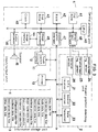
- Fig. 3 shows an example of a navigation system according to the present invention.
- the navigation system according to the present invention comprises an input/output unit 1 for inputting and outputting information relating to route guidance, a present position detecting unit 2 for detecting information relating to the present position of the vehicle, an information storage unit 3 for storing navigation data necessary for calculating an optimal route or display guidance data necessary for guidance, and a central processing unit 4 for route search processing and display guidance processing necessary for route guidance and for controlling the entire system.
- the input/output unit 1 instructs navigation processing to the central processing unit 4 to input destination data at the intention of the driver so that guidance information can be outputted in voice and/or on screen when the driver needs such information and to print out the data after the processing.
- the input unit comprises a touch switch 11 or an operation switch to input the destination using telephone number or coordinates on map or to request route guidance.
- the output unit comprises a display unit 12 for displaying the inputted data on screen or for displaying route guidance automatically on screen at the request of the driver, a printer 13 for printing out the data processed by the central processing unit 4 or the data stored in the information storage unit 3, and a speaker 16 for outputting the route guidance information by voice.
- a voice recognizing device for outputting in voice or a card reader for reading data recorded on IC card or magnetic card.
- a data communication device which stores data necessary for navigation and exchanges data to and from an information center where data necessary for navigation is stored and is offered via communication line at the request of the driver or to and from an information source such as electronic notebook where data specific to the driver such as map data, destination data, etc. are stored in advance.
- the display unit 12 comprises a color CRT or a color liquid crystal display, and all screens necessary for navigation such as target name input screen, route setting screen, sector view screen, intersection view screen, and direction guidance screen at branch point such as intersection are outputted in color display based on map data and guidance data processed by the central processing unit 4, and buttons are displayed, on the screen for setting the route guidance or for switching over guidance or screen during route guidance.
- transit intersection information such as names of transit intersections is given in pop-up color display on the sector view screen when necessary.
- This display unit 12 is installed on an instrument panel near the driver's seat. By watching the sector view, the driver can confirm the present position of the vehicle and can obtain information on the route ahead.
- the display unit 12 is provided with a touch panel 11 to match the display of functional buttons. By touching the button, the above operation is executed based on the inputted signal.
- the input signal generating means comprising this button and the touch switch constitutes the input unit, but detailed description is not given here.
- the present position detecting unit 2 is provided with a GPS receiver 21 utilizing global positioning system (GPS), a beacon receiver 22, a data transceiver for receiving compensation signal of GPS utilizing cellular phone (automobile phone) or FM multiplex signal, an absolute heading sensor 24 comprising a geomagnetic sensor, a relative heading sensor comprising wheel sensor, steering sensor, gyro, etc. and a distance sensor for detecting traveled distance from number of revolutions of wheels.
- GPS global positioning system
- beacon receiver 22 a data transceiver for receiving compensation signal of GPS utilizing cellular phone (automobile phone) or FM multiplex signal
- an absolute heading sensor 24 comprising a geomagnetic sensor
- a relative heading sensor comprising wheel sensor, steering sensor, gyro, etc.
- a distance sensor for detecting traveled distance from number of revolutions of wheels.
- the information storage unit 3 is a data base where all necessary data for navigation system are recorded and comprises files such as map data, intersection data, node data, road data, photograph data, registered point data, guidance point data, destination data, telephone number data, address data, etc.
- the central processing unit 4 comprises a CPU 40 for executing various computation processings, a first ROM 41 for storing programs to execute processing such as route searching and programs for display output control necessary for route guidance and for audio output control necessary for audio guidance and necessary data, a RAM 42 for temporarily storing route guidance information searched such as coordinates, road surface code No., etc.
- a 2nd ROM 43 for storing display information data necessary for route guidance and map display
- an image memory 44 for storing image data used for screen display on the display unit
- an image processor 45 for picking up the image data from the image memory 44 based on the display output control signal from the CPU 40 and for outputting it to the display unit after image processing
- an audio processor 46 for synthesizing voice, phrase, a sizable sentence, sound, etc.
- a communication interface 47 for sending and receiving input/output data by communication
- a sensor input interface 48 for incorporating sensor signal of the present position detecting unit 2
- a clock 49 for recording date and time to internal dialog information.
- route guidance is carried out by screen display and audio output, and the driver can select whether the data should be provided in audio output or not.
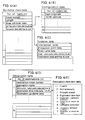
- Fig. 4 to Fig. 6 shows an arrangement example of major data file stored in the information storage unit 3 of the present invention shown in Fig. 3.
- Fig. 4 (A) represents guidance road data file where data necessary for calculating a route by a route calculating means and for providing route guidance are stored.
- data such as road number, length, road attribute data, address and size of configuration data, and address and size of guidance data.
- the road number is set for each direction (outward course and return course) for each road between branch points.
- the road attribute data serving as auxiliary information data for road guidance are the data, as shown in Fig.
- the configuration data has, as shown in Fig. 4 (B), coordinate data comprising east longitude and north latitude of each of several meters of node when each road is divided into a plurality of nodes.
- the guidance data comprises, as shown in Fig. 4 (C), intersection (or branch point) name, precaution point data, road name data, address and size of road name audio data, and address and size of destination data.
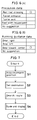
- the precaution point data are the data indicating information such as railroad crossing, tunnel entrance, tunnel exit, road width reduced point, or no suggestion as shown in Fig. 6 (A). These are the data to warn the driver of precaution points such as railroad crossing, tunnel, etc. other than branch points.
- the road name data are, as shown in Fig. 5 (B), the data to indicate road type information such as expressway, municipal expressway, toll road, general road (national road, prefectural road, and others) and also information indicating whether expressway, municipal expressway or toll road is a main line or an approach road. It comprises road type data and in-type number, which is individual number data for each road type.
- the destination data comprises, as shown in Fig. 4 (D), destination road number, destination name, address and size of destination name audio data, destination direction data, and traveling guidance data.
- the destination name includes direction name.
- the destination direction data are the data to indicate information such as invalid (destination direction data is not used), not necessary (no guidance is necessary), straight ahead, rightward direction, diagonally rightward direction, direction to return to right, leftward direction, diagonally leftward direction and direction to return to left.
- the running guidance data are, as shown in Fig. 6 (B), the data for providing guidance as to which lane the vehicle should be driven along when there are two or more lanes and these are the data to indicate "bear right", “bear left”, “bear toward center” or no suggestion.
- Fig. 7 is a flow chart for explaining a flow of the entire navigation system of the present invention.
- Step S1 When the program of route guidance system is started by CPU 51 of the central processing unit 4, the present position of the vehicle is detected by a present position detecting unit 2, and a map of the vicinity of the present position is displayed. Also, the name and other data of the present position are displayed (Step S1). Next, a destination is set using target name, telephone number, address, registered point, etc. of the place or the facility (Step S2), and an optimal route from the present position to the destination is searched (Step S3). When the route has been determined, the present position is traced by the present position detecting unit 2, and route guidance and display are repeatedly performed until the vehicle reaches the destination (Step S4). When an additional route out of the planned route is set before the vehicle reaches the destination, a search area is set. Then, re-searching is carried out in the search area, and route guidance is repeated until the vehicle reaches the destination.
- the present embodiment is to provide direction information for route guidance at branch point in the route guidance and display of the above Step S4.
- the guide branch point on the guidance route necessary for the next guidance according to the present position is called “guidance object branch point”
- guide branch point a branch point requiring guidance and simply located on a leading route
- a guide branch point is searched, which is positioned in a given distance, e.g. 300 m in case of general road and within 600 m in case of expressway, from the guidance object branch point P1. All branch points falling under the above category are acquired, and it is checked whether number of the acquired branch points is 2 or more.
- Fig. 9 (a) there is only one guide branch point (P1 only) within the distance D on the leading route shown by arrow. Accordingly, the direction name nearest to this side, i.e. the direction name shown on a sign at the branch point P1, is displayed for guidance.
- the signs "destination A; destination B" are displayed for guidance.
- guide branch points within the distance D on the leading route shown by arrow are P1, P2, P3 and P4.
- the destination names marked on the sign at the branch point P1 are compared with destination names marked on the signs at the branch points P2, P3, and P4, and the same direction names are searched.
- the direction name"destination B" is displayed for guidance when the vehicle is at the branch point P1, and"destination B"is displayed at the branch point P2.
- Fig. 9 (b) if there are many branch points within the distance D, not only the direction name on the signpost at P1 but destination names on the branch points P2, P3 and P4 are compared with each other in the search processing at the branch point P1. For example, in case there is a direction name common to the branch points P3 and P4, the data may be saved, and direction guidance processing at the branch point P3 may be simplified.
- the processing to prepare directional guidance information is started in case there is further a guide branch point ahead of the guidance object branch point.
- the present invention is not limited to this.
- the processing to prepare direction guidance information may be started to provide direction guidance.
- the vehicle when the vehicle is within a given distance from the guidance object branch point to be guided next, guide branch points existing within a given distance from said guidance object branch point are searched, and direction information is acquired.
- the direction thus acquired is compared with the direction information of the guidance object branch point to be guided next, and the mode of guidance is changed based on the result of the comparison.
- the user can judge whether the vehicle should be driven based on a specific direction information at the first guide branch point according to the mode of guidance, and the user can find the information on direction in advance. Even when the next guide branch point is in near distance and direction guidance is given immediately before that point, the driver can drive the vehicle at ease and with full confidence.
- Fig. 11 and Fig. 12 represent examples for providing direction guidance for a route leading from the outer loop expressway connecting Tokyo - Saitama - Chiba to the metropolitan expressway.
- the signs "Direction Misato; Direction Kashiwa” (straight ahead), and "Direction Tohoku Expressway; Direction Metropolitan Expressway” (left turn) are marked on the signposts.
- signs "Direction Metropolitan Expressway” and "Direction Tohoku Expressway” are marked on the signposts.
- the sign “Direction Metropolitan Expressway” is displayed for guidance when the vehicle is at the branch point P as shown in Fig. 12 (a), and the same sign "Direction Metropolitan Expressway” is displayed for guidance at the branch point Q.
- the directional guidance is not only displayed on screen but guidance by voice or guidance by both voice and screen may be simultaneously used.
- the signs "direction A; direction B" may be displayed on screen and only the information "direction B” may be given by voice.
- two signs "direction A and direction B” may be displayed on screen, and by changing color, one of these signs may be emphasized or highlighted.
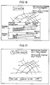
- Fig. 13 shows a screen displaying a name of an IC where the vehicle is to be diverted from the course when driving along expressway or toll road.
- the system of the present invention is designed in such manner that, when the vehicle approaches the next branch point, distance and direction to the branch point are automatically outputted in voice. Also, when an additional audio switch is operated, distance and direction to the next branch point are outputted in voice at any time.
- the additional audio switch is utilized and when the additional audio switch is operated while driving along expressway or toll road, distance and direction to the next branch point is outputted in voice.
- name of an IC where the vehicle is to be diverted from the course is displayed in larger size at the center of the route guidance map screen as shown in Fig. 13, and the remaining distance is also displayed. In Fig.
- This IC name display screen can be closed by key operation, returning to the route guidance map screen. Of course, it may be designed in such manner that the screen is displayed for a given time period and is then automatically closed.
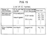
- the central processing unit 4 searches a route from the present position to the destination (S11 and S12). If there is an expressway or a toll road on the suggested route, a list of IC names is prepared indicating names and positions of ICs where the vehicle is to join or to be diverted from the course of expressway or toll road (S13) as shown in Fig. 15.
- a list of IC names is prepared indicating names and positions of ICs where the vehicle is to join or to be diverted from the course of expressway or toll road (S13) as shown in Fig. 15.
- the present position is calculated by the present position detecting unit 2, and it is judged whether the vehicle has arrived the destination or not (S14 and S15). Next, it is judged whether the additional audio switch has been pressed or not. If pressed, distance and direction to the next branch point are outputted in voice (S16 and S17). Next, it is checked that the road where the vehicle is currently driven along is an expressway or a toll road or not. If it is expressway or toll road, the present position is compared with the list of IC names and the name of the IC where the vehicle should be diverted from the course is searched. Then, the distance to the IC is calculated, and the IC name thus obtained and the distance to the IC are displayed (S18 and S21).
- the means to notify the name of the IC where the vehicle is to be diverted from the course it may be calculated at which IC the vehicle should be diverted from the course, i.e. after how many ICs from the present position (position where the additional audio switch has been operated), and the IC where the vehicle is to be diverted from the course may be informed by the number of ICs from the present position, e.g. "This is the route to divert from the course at the third IC.”
- the number of IC can be obtained by calculating how many ICs are present between the present position and the IC where the vehicle is to be diverted from the course based on the route information obtained by route searching.
- each IC by providing each IC with road data, it can be obtained by calculating joints of the road stored in the route information memory means and existing on the route up to the IC where the vehicle is to be diverted. Because the distance to the next IC is relatively long when driving along expressway and voice guidance such as "no specific matter for the time being" by the additional audio operating means, the information effective to the operation can be given by providing the name of IC where the vehicle is to be diverted from the course.
- a list of IC names where the vehicle should be diverted from the course on expressway or toll road and information of positions of ICs are stored in memory.
- the present position is compared with the list of IC names, and the name of the IC where the vehicle should be diverted next and the distance to said IC are detected and displayed.
- the name of the IC where the vehicle is to be diverted from the course is given when necessary by the additional audio switch, and there is no need to display the name of IC at all times when driving along expressway, and guidance can be given for the name of IC where the vehicle is to be diverted from the course. At the same time, it is possible to provide guidance for the next branch point by voice.
- Fig. 16 is a drawing to show a vehicle velocity setting screen. This is popped up in lower portion of the guidance map screen by operating the operation key provided on the input/output unit of Fig. 3.
- the vehicle velocity is displayed in graph in the range from 0 to 160 km/h for expressway and general road. By changing the shaded portion on the screen using a vehicle velocity setting key, the velocity can be selected.
- the vehicle velocity to cope with the actual condition can be set by taking the road condition into consideration. For example, by considering driving condition such as unexpected congestion due to traffic accident or road construction, the vehicle velocity is set. In the example shown in the figure, it is set to 80 km/h for expressway and 30 km/h for general road.
- the setting is completed, it is returned to the pop-up screen of the vehicle velocity setting, and the route guidance view is displayed.
- expected time to arrive the destination is calculated by the processing to be described later. Because the vehicle velocity for each road type is set by taking road condition into consideration, the expected time of arrival is properly calculated according to the driving conditions. The expected time of arrival thus calculated is displayed in a clock provided at a position easy to look at in upper portion of the guidance screen as shown in Fig. 17, and it is outputted in voice if necessary.
- the central processing unit 4 searches a route from the present position to the destination and calculates length of expressway and length of general road in the searched route (S31 to S33).
- the present position is calculated by the present position detecting unit 2, and it is judged whether the vehicle has arrived at the destination or not (S34 and S35).
- it is judged whether the road where the vehicle is currently driven is expressway or general road by referring to road name data of the information storage unit 3, and the remaining distance to the destination is obtained by subtracting the traveled distance from the length of expressway and length of general road calculated in the beginning (S36 to S38).
- the remaining distance thus obtained is divided by average vehicle velocity on expressway and general road set on the screen of Fig. 16 to obtain the time required to drive along expressway and general road.
- the time required from the present position to the destination is calculated (S39 and S40).
- the time required thus calculated is added to the time on the clock 49 of the central processing unit, and the expected time of arrival is obtained and displayed (S41).
- the remaining distance on the route can be calculated for each road type such as expressway or general road, and the time required can be accurately obtained by setting average vehicle velocity for each road type. Also, a means is provided so that the user can operate and set the average vehicle velocity. As a result, the time required to match the desired driving condition can be calculated.
- the driving time can be calculated at average vehicle velocity suitable for each type of road by weighted processing corresponding to road type, road width and number of intersections, and it is possible to calculate the expected time of arrival properly and to provide guidance.
- the expected time of arrival can be calculated by adding or totalizing a given value or values to the distance of each road. For instance, to actual length of 1 km of national road, the time can be calculated by assuming that actual length of prefectural road is by 1.5 times of that of national road, i.e. prefectural road is 1.5 km in length.
- the expected time of arrival may be calculated by changing, not the distance but the average vehicle velocity itself, i.e. by adding or subtracting a given value.
- the expected time of arrival may be automatically calculated by utilizing external information obtained by the beacon receiver 22 and the data transceiver 23, or the expected time of arrival may be calculated by manual operation based on the obtained external information.
- the data of road condition on the route ahead can be added in the calculation of the expected time of arrival, and accuracy of the time calculation is improved.
- expected time of arrival at the destination is calculated and guided as the vehicle moves. Also, by making it possible to set average vehicle velocity for each road type and by changing average vehicle velocity as the driver wishes, it is possible to estimate the time of arrival at high accuracy. Because the remaining distance from the present position to the destination is calculated for each road type and expected time of arrival is calculated and displayed based on the remaining distance, the time of arrival is not deviated from the calculated time due to waiting for traffic signal at intersection or when the vehicle is to be stopped or delayed due to traffic congestion, and proper guidance can be given on the expected time of arrival at the destination.
Landscapes
- Engineering & Computer Science (AREA)
- Radar, Positioning & Navigation (AREA)
- Remote Sensing (AREA)
- Automation & Control Theory (AREA)
- Physics & Mathematics (AREA)
- General Physics & Mathematics (AREA)
- Navigation (AREA)
Abstract
Description
- The present invention relates to vehicle navigation systems, which provide directional guidance at branch points such as intersections along with other route guidance in response to inputting place data such as destination data or transit points, searching a route from the present position or the starting point to the destination and travelling of the vehicle along the route.
- In the past, various types of route guiding devices have been proposed to able smooth driving along a road unfamiliar to the driver. In such devices, the driver is guided along a road to a destination after inputting the destination. Some of the route guiding devices are known to have functions to provide directional guidance when the vehicle passes through branch points such as intersections.
- As shown in Fig. 1, in case a leading route is branched off at a branch point P1 and is further branched off at a branch point P2 in relatively near distance from the point P1 and is to be directed toward direction B, the directional guidance as known in the past is as follows: If there are signs of "destination C" (straight ahead) and "destination A and destination B" (right turn) at the branch point P1, guidance sign of "destination A; destination B" is displayed at first as shown in Fig. 2(a). Then, at the branch point P2, the guidance sign for "destination B" is displayed as shown in Fig. 2(b) (Note: The following description frequently also uses the term "direction A, B,..." or "to A, B..." instead of "destination A, B...").
- In the directional guidance known in the past, all destination names marked on the signs such as "direction A; direction B" are displayed at the first branch point where the guidance is to be provided. Then, the guidance for "direction B" is provided at the second branch point. Because guidance is given for two or more directions at the first branch point, it is difficult to understand, and the driver may not have complete knowledge that the vehicle is driven toward direction B until the vehicle has actually passed over the first branch point. In particular, if the next branch point is in near distance, the guidance for direction B is offered to the driver only immediately before the branch point.
- A route guiding device has been known in the past, in which distance and time required to the destination are displayed on screen. In case expressway is included in the guidance route, the name of the nearest interchange ("IC") is displayed while driving along expressway, but the name of IC where the vehicle should be diverted from the course on the expressway is not displayed until the vehicle approaches the IC in a given distance. As described above, guidance information to be offered is not many on expressway, and the driver cannot often obtain guidance even when he or she wants to confirm the guidance information.
- Also, in the route guiding device known in the past, the expected time of arrival at the destination can be calculated from a preset average vehicle velocity. In fact, however, there may be some deviation in the suggested time of arrival depending upon conditions or situations of the road leading to the destination.
- It is an object of the present invention to provide a navigation system, which can ensure directional guidance easy to understand and reliable.
- It is another object of the present invention to provide a navigation system, by which it is possible to judge whether the vehicle should be driven or not according to information on a specific destination at a first guide branch point.
- It is still another object of the present invention to provide a navigation system, by which it is possible to identify information of a direction to be driven in advance.
- It is still another object of the present invention to provide a navigation system, by which, while driving along an expressway or a toll road, name of an IC where the vehicle should be diverted from the course on expressway or toll road can be displayed on a guidance screen.
- It is yet still another object of the present invention to provide a navigation system, by which it is possible to inform the driver with information on driving of the vehicle and with suggestion on the expected time of arrival.
- The navigation system according to the present invention comprises a guidance control means, whereby, when the present position of a vehicle is within a given distance from a guidance object branch point to be guided next, guide branch points existing within a given distance from said guidance object branch point to be guided next are searched, directional information at the searched guide branch points is acquired, and when the direction information has been acquired, the acquired directional information is compared with the direction information at said guidance object branch point to be guided next, and mode of guidance is changed based on the result of the comparison.
- The navigation system according to the present invention comprises a route calculating means for calculating a route from an inputted destination and for preparing route information including a list of names of ICs where the vehicle is to be diverted from the course on an expressway or a toll road and information of positions of said ICs when there is an expressway or a toll road in the course of the suggested route, a means for prompting display of name of the IC where the vehicle is to be diverted from the course, and a means for searching name of an IC where the vehicle is to be diverted from the course on expressway or toll road next by comparing the present position with the list of names of ICs when the suggested road currently driving along is an expressway or a toll road, and for providing guidance by calculating the distance to said IC.
- The navigation system for vehicles for searching a route by inputting destination data and for providing route guidance, wherein expected time of arrival at the destination is calculated and suggested as the vehicle moves. Also, the navigation system according to the present invention comprises a vehicle velocity setting means for setting average velocity for each type of road, a present position detecting means for calculating the present position of the vehicle, a route calculating means for calculating a route and also a distance for each type of roads in the suggested route, and a guidance control means for calculating the remaining distance for each type of roads on the suggested route and for obtaining and displaying expected time of arrival by calculating the time required to reach the destination from the preset average vehicle velocity for each type of road and the calculated remaining distance and by adding the calculated time to the current time.
- Fig. 1 is a map display showing pior art direction guidance;
- Figs. 2(a) and (b) are screen displays illustrating conventional type direction guidance;
- Fig. 3 is a block diagram of a navigation system according to the present invention;
- Fig. 4 represents an arrangement example of major data file according to the present invention;
- Fig. 5 represents an arrangement example of major data file according to the present invention;
- Fig. 6 represents an arrangement example of major data file according to the present invention;
- Fig. 7 is a flow chart for explaining a flow of the entire system;
- Fig. 8 is a flow chart to prepare direction guidance information according to the present invention;
- Fig. 9 is a drawing for explaining processing to acquire number of guidance object branch points;
- Fig. 10 shows guidance screens;
- Fig. 11 is a drawing for explaining direction guidance;
- Fig. 12 shows guidance screens;
- Fig. 13 shows a display screen at an IC where the vehicle is to be diverted from main line;
- Fig. 14 is a flow chart of processing to display name of an IC according to the present invention;
- Fig. 15 represents a list of names of ICs;
- Fig. 16 represents a vehicle velocity setting screen of the present invention;
- Fig. 17 represents a screen to display expected time of arrival; and
- Fig. 18 is a flow chart of processing to display the expected time of arrival according to the present invention;
- In the following, description will be given on embodiments of the present invention in connection with the drawings.
- Fig. 3 shows an example of a navigation system according to the present invention. As shown in Fig. 3, the navigation system according to the present invention comprises an input/
output unit 1 for inputting and outputting information relating to route guidance, a presentposition detecting unit 2 for detecting information relating to the present position of the vehicle, aninformation storage unit 3 for storing navigation data necessary for calculating an optimal route or display guidance data necessary for guidance, and acentral processing unit 4 for route search processing and display guidance processing necessary for route guidance and for controlling the entire system. - The input/
output unit 1 instructs navigation processing to thecentral processing unit 4 to input destination data at the intention of the driver so that guidance information can be outputted in voice and/or on screen when the driver needs such information and to print out the data after the processing. As the means to execute the functions, the input unit comprises atouch switch 11 or an operation switch to input the destination using telephone number or coordinates on map or to request route guidance. The output unit comprises adisplay unit 12 for displaying the inputted data on screen or for displaying route guidance automatically on screen at the request of the driver, aprinter 13 for printing out the data processed by thecentral processing unit 4 or the data stored in theinformation storage unit 3, and aspeaker 16 for outputting the route guidance information by voice. - In this case, it is also possible to add a voice recognizing device for outputting in voice or a card reader for reading data recorded on IC card or magnetic card. Also, it is possible to add a data communication device, which stores data necessary for navigation and exchanges data to and from an information center where data necessary for navigation is stored and is offered via communication line at the request of the driver or to and from an information source such as electronic notebook where data specific to the driver such as map data, destination data, etc. are stored in advance.
- The
display unit 12 comprises a color CRT or a color liquid crystal display, and all screens necessary for navigation such as target name input screen, route setting screen, sector view screen, intersection view screen, and direction guidance screen at branch point such as intersection are outputted in color display based on map data and guidance data processed by thecentral processing unit 4, and buttons are displayed, on the screen for setting the route guidance or for switching over guidance or screen during route guidance. In particular, transit intersection information such as names of transit intersections is given in pop-up color display on the sector view screen when necessary. - This
display unit 12 is installed on an instrument panel near the driver's seat. By watching the sector view, the driver can confirm the present position of the vehicle and can obtain information on the route ahead. Thedisplay unit 12 is provided with atouch panel 11 to match the display of functional buttons. By touching the button, the above operation is executed based on the inputted signal. The input signal generating means comprising this button and the touch switch constitutes the input unit, but detailed description is not given here. - The present
position detecting unit 2 is provided with aGPS receiver 21 utilizing global positioning system (GPS), abeacon receiver 22, a data transceiver for receiving compensation signal of GPS utilizing cellular phone (automobile phone) or FM multiplex signal, anabsolute heading sensor 24 comprising a geomagnetic sensor, a relative heading sensor comprising wheel sensor, steering sensor, gyro, etc. and a distance sensor for detecting traveled distance from number of revolutions of wheels. - The
information storage unit 3 is a data base where all necessary data for navigation system are recorded and comprises files such as map data, intersection data, node data, road data, photograph data, registered point data, guidance point data, destination data, telephone number data, address data, etc. - The
central processing unit 4 comprises aCPU 40 for executing various computation processings, afirst ROM 41 for storing programs to execute processing such as route searching and programs for display output control necessary for route guidance and for audio output control necessary for audio guidance and necessary data, aRAM 42 for temporarily storing route guidance information searched such as coordinates, road surface code No., etc. of the preset destination or data under computation, a2nd ROM 43 for storing display information data necessary for route guidance and map display, animage memory 44 for storing image data used for screen display on the display unit, animage processor 45 for picking up the image data from theimage memory 44 based on the display output control signal from theCPU 40 and for outputting it to the display unit after image processing, anaudio processor 46 for synthesizing voice, phrase, a sizable sentence, sound, etc. read from theinformation storage unit 3 based on the audio output control signal from the CPU for outputting them to thespeaker 16 after converting to analog signal, acommunication interface 47 for sending and receiving input/output data by communication, asensor input interface 48 for incorporating sensor signal of the presentposition detecting unit 2, and aclock 49 for recording date and time to internal dialog information. Here, route guidance is carried out by screen display and audio output, and the driver can select whether the data should be provided in audio output or not. - Fig. 4 to Fig. 6 shows an arrangement example of major data file stored in the
information storage unit 3 of the present invention shown in Fig. 3. Fig. 4 (A) represents guidance road data file where data necessary for calculating a route by a route calculating means and for providing route guidance are stored. In each of the number of roads (n), there are provided data such as road number, length, road attribute data, address and size of configuration data, and address and size of guidance data. The road number is set for each direction (outward course and return course) for each road between branch points. The road attribute data serving as auxiliary information data for road guidance are the data, as shown in Fig. 5 (A), showing that the road is overpass, road alongside overpass, underpass, or road alongside underpass, and also providing information of the number of lanes. The configuration data has, as shown in Fig. 4 (B), coordinate data comprising east longitude and north latitude of each of several meters of node when each road is divided into a plurality of nodes. - The guidance data comprises, as shown in Fig. 4 (C), intersection (or branch point) name, precaution point data, road name data, address and size of road name audio data, and address and size of destination data. The precaution point data are the data indicating information such as railroad crossing, tunnel entrance, tunnel exit, road width reduced point, or no suggestion as shown in Fig. 6 (A). These are the data to warn the driver of precaution points such as railroad crossing, tunnel, etc. other than branch points. The road name data are, as shown in Fig. 5 (B), the data to indicate road type information such as expressway, municipal expressway, toll road, general road (national road, prefectural road, and others) and also information indicating whether expressway, municipal expressway or toll road is a main line or an approach road. It comprises road type data and in-type number, which is individual number data for each road type.
- The destination data comprises, as shown in Fig. 4 (D), destination road number, destination name, address and size of destination name audio data, destination direction data, and traveling guidance data. The destination name includes direction name. The destination direction data are the data to indicate information such as invalid (destination direction data is not used), not necessary (no guidance is necessary), straight ahead, rightward direction, diagonally rightward direction, direction to return to right, leftward direction, diagonally leftward direction and direction to return to left. The running guidance data are, as shown in Fig. 6 (B), the data for providing guidance as to which lane the vehicle should be driven along when there are two or more lanes and these are the data to indicate "bear right", "bear left", "bear toward center" or no suggestion.
- Next, description will be given on a flow of processing of the navigation system for vehicles of the present invention. Fig. 7 is a flow chart for explaining a flow of the entire navigation system of the present invention.
- When the program of route guidance system is started by CPU 51 of the
central processing unit 4, the present position of the vehicle is detected by a presentposition detecting unit 2, and a map of the vicinity of the present position is displayed. Also, the name and other data of the present position are displayed (Step S1). Next, a destination is set using target name, telephone number, address, registered point, etc. of the place or the facility (Step S2), and an optimal route from the present position to the destination is searched (Step S3). When the route has been determined, the present position is traced by the presentposition detecting unit 2, and route guidance and display are repeatedly performed until the vehicle reaches the destination (Step S4). When an additional route out of the planned route is set before the vehicle reaches the destination, a search area is set. Then, re-searching is carried out in the search area, and route guidance is repeated until the vehicle reaches the destination. - The present embodiment is to provide direction information for route guidance at branch point in the route guidance and display of the above Step S4. In the following, the guide branch point on the guidance route necessary for the next guidance according to the present position is called "guidance object branch point", and a branch point requiring guidance and simply located on a leading route is called "guide branch point".
- Description is now given on processing for direction guidance referring to Fig. 8 and Fig. 9.
- In case there is further a guide branch point ahead of the guidance object branch point, processing to prepare direction guidance as shown in Fig. 8 is started. In this processing, a guide branch point is searched, which is positioned in a given distance, e.g. 300 m in case of general road and within 600 m in case of expressway, from the guidance object branch point P1. All branch points falling under the above category are acquired, and it is checked whether number of the acquired branch points is 2 or more. In the case shown in Fig. 9 (a), there is only one guide branch point (P1 only) within the distance D on the leading route shown by arrow. Accordingly, the direction name nearest to this side, i.e. the direction name shown on a sign at the branch point P1, is displayed for guidance. In the case shown in Fig. 1, the signs "destination A; destination B" are displayed for guidance. In the case shown in Fig 9 (b), guide branch points within the distance D on the leading route shown by arrow are P1, P2, P3 and P4. Thus, the destination names marked on the sign at the branch point P1 are compared with destination names marked on the signs at the branch points P2, P3, and P4, and the same direction names are searched. As the result of the searching, if there is the same direction name, only this name is displayed for guidance. For example, in the case shown in Fig. 1, the direction name"destination B"is displayed for guidance when the vehicle is at the branch point P1, and"destination B"is displayed at the branch point P2.
- As shown in Fig. 9 (b), if there are many branch points within the distance D, not only the direction name on the signpost at P1 but destination names on the branch points P2, P3 and P4 are compared with each other in the search processing at the branch point P1. For example, in case there is a direction name common to the branch points P3 and P4, the data may be saved, and direction guidance processing at the branch point P3 may be simplified.
- In the above description, the processing to prepare directional guidance information is started in case there is further a guide branch point ahead of the guidance object branch point. However, the present invention is not limited to this. When the vehicle is at a point in a given distance from the guidance object branch point or it is in a given distance to this side from the guidance object branch point and the guidance object branch point has direction information, or in case a guide branch point located in a given distance to this side of the guidance object branch point has direction information, or there are two or more direction informations at the guidance object branch point, the processing to prepare direction guidance information may be started to provide direction guidance.
- In the present embodiment, when the vehicle is within a given distance from the guidance object branch point to be guided next, guide branch points existing within a given distance from said guidance object branch point are searched, and direction information is acquired. The direction thus acquired is compared with the direction information of the guidance object branch point to be guided next, and the mode of guidance is changed based on the result of the comparison. As a result, the user can judge whether the vehicle should be driven based on a specific direction information at the first guide branch point according to the mode of guidance, and the user can find the information on direction in advance. Even when the next guide branch point is in near distance and direction guidance is given immediately before that point, the driver can drive the vehicle at ease and with full confidence.
- Fig. 11 and Fig. 12 represent examples for providing direction guidance for a route leading from the outer loop expressway connecting Tokyo - Saitama - Chiba to the metropolitan expressway. At a branch point P, the signs "Direction Misato; Direction Kashiwa" (straight ahead), and "Direction Tohoku Expressway; Direction Metropolitan Expressway" (left turn) are marked on the signposts. At a branch point Q, signs "Direction Metropolitan Expressway" and "Direction Tohoku Expressway" are marked on the signposts. In this case, the sign "Direction Metropolitan Expressway" is displayed for guidance when the vehicle is at the branch point P as shown in Fig. 12 (a), and the same sign "Direction Metropolitan Expressway" is displayed for guidance at the branch point Q.
- It is needless to say that the directional guidance is not only displayed on screen but guidance by voice or guidance by both voice and screen may be simultaneously used. In the example of Fig. 9, for instance, the signs "direction A; direction B" may be displayed on screen and only the information "direction B" may be given by voice. Or, in the example of Fig. 9, two signs "direction A and direction B" may be displayed on screen, and by changing color, one of these signs may be emphasized or highlighted.
- Next, description will be given on an example to provide guidance for the name of IC where the vehicle is to be diverted from the course on expressway or toll road, referring to route guidance and display of Step S4 in Fig. 7.
- Fig. 13 shows a screen displaying a name of an IC where the vehicle is to be diverted from the course when driving along expressway or toll road.
- In the system of the present invention, it is designed in such manner that, when the vehicle approaches the next branch point, distance and direction to the branch point are automatically outputted in voice. Also, when an additional audio switch is operated, distance and direction to the next branch point are outputted in voice at any time. In the system of the present invention, the additional audio switch is utilized and when the additional audio switch is operated while driving along expressway or toll road, distance and direction to the next branch point is outputted in voice. At the same time, name of an IC where the vehicle is to be diverted from the course is displayed in larger size at the center of the route guidance map screen as shown in Fig. 13, and the remaining distance is also displayed. In Fig. 13, it is displayed that the vehicle is driven along the metropolitan expressway (the nearest IC is Meguro), and that the vehicle is to be diverted from the course at Ebara IC of the metropolitan expressway. The distance to this IC is also displayed as 9 km. This IC name display screen can be closed by key operation, returning to the route guidance map screen. Of course, it may be designed in such manner that the screen is displayed for a given time period and is then automatically closed.
- Next, description will be given on processing to display the name of IC where the vehicle is to be diverted from the course referring to Fig. 14.
- When the destination is inputted by operating the input/
output unit 1 shown in Fig. 3, thecentral processing unit 4 searches a route from the present position to the destination (S11 and S12). If there is an expressway or a toll road on the suggested route, a list of IC names is prepared indicating names and positions of ICs where the vehicle is to join or to be diverted from the course of expressway or toll road (S13) as shown in Fig. 15. When joining the course at an IC, and the name "Kita-Ikebukuro" of IC to join is given in voice. When the vehicle has joined the course at the IC, the name of the next IC "Nishi-Kanda" is given for guidance. Then, the present position is calculated by the presentposition detecting unit 2, and it is judged whether the vehicle has arrived the destination or not (S14 and S15). Next, it is judged whether the additional audio switch has been pressed or not. If pressed, distance and direction to the next branch point are outputted in voice (S16 and S17). Next, it is checked that the road where the vehicle is currently driven along is an expressway or a toll road or not. If it is expressway or toll road, the present position is compared with the list of IC names and the name of the IC where the vehicle should be diverted from the course is searched. Then, the distance to the IC is calculated, and the IC name thus obtained and the distance to the IC are displayed (S18 and S21). When this processing has been executed until the vehicle reaches the destination, and it is completed when the vehicle arrives at the destination. When driving along expressway or toll road, even when the additional audio operating means has been operated, proper guidance may not be provided because the distance between the entry point and the exit point on the road is too long. When operation of the additional audio operating means has been operated, it is detected that the vehicle is currently driven along a specific road which has entrance to or exit from expressway or toll road, and the information effective to the operation can be provided by outputting guidance relating to the next intersection (branch point) and by notifying the name of an IC where the vehicle is to be diverted from the course. - In the present embodiment, description has been given on the case relating to expressway or toll road, while it is needless to say that the system of the present invention can be applied to other type of road having IC such as bypass road, overpass, etc.
- Further, as the means to notify the name of the IC where the vehicle is to be diverted from the course, it may be calculated at which IC the vehicle should be diverted from the course, i.e. after how many ICs from the present position (position where the additional audio switch has been operated), and the IC where the vehicle is to be diverted from the course may be informed by the number of ICs from the present position, e.g. "This is the route to divert from the course at the third IC." For example, the number of IC can be obtained by calculating how many ICs are present between the present position and the IC where the vehicle is to be diverted from the course based on the route information obtained by route searching. Also, by providing each IC with road data, it can be obtained by calculating joints of the road stored in the route information memory means and existing on the route up to the IC where the vehicle is to be diverted. Because the distance to the next IC is relatively long when driving along expressway and voice guidance such as "no specific matter for the time being" by the additional audio operating means, the information effective to the operation can be given by providing the name of IC where the vehicle is to be diverted from the course.
- In the present embodiment, when there is an expressway or a toll road in the leading route after the route has been searched, a list of IC names where the vehicle should be diverted from the course on expressway or toll road and information of positions of ICs are stored in memory. When the name of IC where the vehicle is to be diverted from the course is guided by the additional audio switch when driving along expressway or toll road, the present position is compared with the list of IC names, and the name of the IC where the vehicle should be diverted next and the distance to said IC are detected and displayed. In the present invention, the name of the IC where the vehicle is to be diverted from the course is given when necessary by the additional audio switch, and there is no need to display the name of IC at all times when driving along expressway, and guidance can be given for the name of IC where the vehicle is to be diverted from the course. At the same time, it is possible to provide guidance for the next branch point by voice.
- Next, description will be given on an example to provide information on expected time of arrival at the destination as the vehicle moves, referring to route guidance and display in Step S4 shown in Fig. 7.
- Fig. 16 is a drawing to show a vehicle velocity setting screen. This is popped up in lower portion of the guidance map screen by operating the operation key provided on the input/output unit of Fig. 3. The vehicle velocity is displayed in graph in the range from 0 to 160 km/h for expressway and general road. By changing the shaded portion on the screen using a vehicle velocity setting key, the velocity can be selected. In case the user can receive congestion information or time required on the road at real time by communication means such as VICS, the vehicle velocity to cope with the actual condition can be set by taking the road condition into consideration. For example, by considering driving condition such as unexpected congestion due to traffic accident or road construction, the vehicle velocity is set. In the example shown in the figure, it is set to 80 km/h for expressway and 30 km/h for general road. When the setting is completed, it is returned to the pop-up screen of the vehicle velocity setting, and the route guidance view is displayed.
- When average vehicle velocity is set for each road type such as expressway, general road, etc., expected time to arrive the destination is calculated by the processing to be described later. Because the vehicle velocity for each road type is set by taking road condition into consideration, the expected time of arrival is properly calculated according to the driving conditions. The expected time of arrival thus calculated is displayed in a clock provided at a position easy to look at in upper portion of the guidance screen as shown in Fig. 17, and it is outputted in voice if necessary.
- Next, description will be given on processing to display the expected time of arrival referring to Fig. 18.
- When the destination data is inputted by the input/
output unit 1 of Fig. 3, thecentral processing unit 4 searches a route from the present position to the destination and calculates length of expressway and length of general road in the searched route (S31 to S33). Next, the present position is calculated by the presentposition detecting unit 2, and it is judged whether the vehicle has arrived at the destination or not (S34 and S35). Next, it is judged whether the road where the vehicle is currently driven is expressway or general road by referring to road name data of theinformation storage unit 3, and the remaining distance to the destination is obtained by subtracting the traveled distance from the length of expressway and length of general road calculated in the beginning (S36 to S38). Next, the remaining distance thus obtained is divided by average vehicle velocity on expressway and general road set on the screen of Fig. 16 to obtain the time required to drive along expressway and general road. By adding these values, the time required from the present position to the destination is calculated (S39 and S40). The time required thus calculated is added to the time on theclock 49 of the central processing unit, and the expected time of arrival is obtained and displayed (S41). When this processing is executed until the vehicle reaches the destination, the processing is completed. - As described above, the remaining distance on the route can be calculated for each road type such as expressway or general road, and the time required can be accurately obtained by setting average vehicle velocity for each road type. Also, a means is provided so that the user can operate and set the average vehicle velocity. As a result, the time required to match the desired driving condition can be calculated.
- In calculating the expected time of arrival, the driving time can be calculated at average vehicle velocity suitable for each type of road by weighted processing corresponding to road type, road width and number of intersections, and it is possible to calculate the expected time of arrival properly and to provide guidance. In the weighted processing, the expected time of arrival can be calculated by adding or totalizing a given value or values to the distance of each road. For instance, to actual length of 1 km of national road, the time can be calculated by assuming that actual length of prefectural road is by 1.5 times of that of national road, i.e. prefectural road is 1.5 km in length. Also, the expected time of arrival may be calculated by changing, not the distance but the average vehicle velocity itself, i.e. by adding or subtracting a given value.
- The expected time of arrival may be automatically calculated by utilizing external information obtained by the
beacon receiver 22 and thedata transceiver 23, or the expected time of arrival may be calculated by manual operation based on the obtained external information. In particular, in case information from an external organization such as VICS, ATIS, etc. is utilized, the data of road condition on the route ahead can be added in the calculation of the expected time of arrival, and accuracy of the time calculation is improved. - Even when external information such as VICS, ATIS, etc. can be utilized, the information for all roads may not be necessarily obtained. Therefore, by calculating the expected time of arrival based on the remaining distance as in the present invention, proper guidance can be provided for calculation of the expected time of arrival even in case the external information is not available.
- In the present embodiment, expected time of arrival at the destination is calculated and guided as the vehicle moves. Also, by making it possible to set average vehicle velocity for each road type and by changing average vehicle velocity as the driver wishes, it is possible to estimate the time of arrival at high accuracy. Because the remaining distance from the present position to the destination is calculated for each road type and expected time of arrival is calculated and displayed based on the remaining distance, the time of arrival is not deviated from the calculated time due to waiting for traffic signal at intersection or when the vehicle is to be stopped or delayed due to traffic congestion, and proper guidance can be given on the expected time of arrival at the destination.
Claims (5)
- A navigation system for vehicles for calculating a route from the present position of a vehicle to a destination and for providing guidance through branch points based on the calculated route, said system comprising:a) means responsive to the vehicle being within a first given distance from a next approaching branch point requiring guidance, for searching for branch points existing along the route within a second given distance following the next approaching branch point;b) means for acquiring sign route information for any next following branch point found by said searching means;c) means for comparing said acquired route information with route information of the next approaching branch point; andd) means for eliminating non-common route information from the sign of the next approaching branch point according to the result of the comparison.
- A system according to Claim 1, comprising:a present position detecting means for calculating the present position of the vehicle;an input means for inputting information necessary for calculating the route;an output means for outputting information for route guidance;an information memory means for storing all data necessary for providing guidance including destination information;a route calculating means for calculating the route based on the information inputted by said input means;a route information memory means for storing information of the route calculated by said route calculating means; anda guidance control means for reading the destination information at the next approaching branch point by said route information memory means based on the route calculated by said route calculating means and on the present position detected by said present position detecting means and for outputting said information to said output means, whereby:said guidance control means searches guide branch points existing within a given distance from said next approaching branch point stored in said route information memory means when the present position detected by said present position detecting means is within a given distance from the next approaching branch point, acquires direction information at said guide branch point, compares the acquired destination information with destination information of said next approaching branch point, and changes mode of guidance for destination information based on the results of the comparison.
- A system according to Claim 2, wherein said guidance control means compares the directional information at the next approaching branch point, and if the destination information matches, only said matching direction information is outputted to said output means, and guidance is provided for directional guidance at the next approaching branch point.
- A system according to Claim 2 or 3, wherein said output means comprises a display means, and said guidance control means compares the acquired destination information at the guide branch point with destination information at the next approaching branch point, and if the destination information matches, said matching destination information is displayed in emphasis by said display means.
- A system according to Claim 2, 3, or 4, wherein said output means comprises a display means and a voice announcing means, and said guidance control means compares the acquired destination information at the guide branch point with destination information at the next approaching branch point, and if the destination information matches, the destination information of the next approaching branch point is outputted to said display means and the matching destination information is outputted in voice by said voice announcing means.
Applications Claiming Priority (9)
| Application Number | Priority Date | Filing Date | Title |
|---|---|---|---|
| JP21786795A JP3341803B2 (en) | 1995-08-25 | 1995-08-25 | Vehicle navigation system |
| JP21786795 | 1995-08-25 | ||
| JP217867/95 | 1995-08-25 | ||
| JP25337095A JPH0996539A (en) | 1995-09-29 | 1995-09-29 | Navigation device for vehicle |
| JP25337095 | 1995-09-29 | ||
| JP253369/95 | 1995-09-29 | ||
| JP25336995 | 1995-09-29 | ||
| JP25336995A JP3400203B2 (en) | 1995-09-29 | 1995-09-29 | Vehicle navigation system |
| JP253370/95 | 1995-09-29 |
Publications (3)
| Publication Number | Publication Date |
|---|---|
| EP0762080A2 true EP0762080A2 (en) | 1997-03-12 |
| EP0762080A3 EP0762080A3 (en) | 1998-06-17 |
| EP0762080B1 EP0762080B1 (en) | 2002-03-27 |
Family
ID=27330077
Family Applications (1)
| Application Number | Title | Priority Date | Filing Date |
|---|---|---|---|
| EP96113633A Expired - Lifetime EP0762080B1 (en) | 1995-08-25 | 1996-08-26 | Navigation system for vehicles |
Country Status (3)
| Country | Link |
|---|---|
| US (1) | US5928308A (en) |
| EP (1) | EP0762080B1 (en) |
| DE (1) | DE69620084T2 (en) |
Cited By (4)
| Publication number | Priority date | Publication date | Assignee | Title |
|---|---|---|---|---|
| EP1030165A1 (en) * | 1998-06-12 | 2000-08-23 | Mitsubishi Denki Kabushiki Kaisha | Navigation device |
| GB2395272A (en) * | 2002-09-05 | 2004-05-19 | Denso Corp | Navigation device including a method and display for listing entrances to and exits from expressways |
| EP2261877A1 (en) * | 2000-09-20 | 2010-12-15 | Pioneer Corporation | Navigation system and method |
| CN109383513A (en) * | 2017-08-04 | 2019-02-26 | 郑州宇通客车股份有限公司 | Environmental sanitation cleaning vehicle automatic Pilot control method and control system |
Families Citing this family (29)
| Publication number | Priority date | Publication date | Assignee | Title |
|---|---|---|---|---|
| JP3581559B2 (en) * | 1998-04-22 | 2004-10-27 | 株式会社ザナヴィ・インフォマティクス | Route search device |
| US6285950B1 (en) * | 1999-05-13 | 2001-09-04 | Alpine Electronics, Inc. | Vehicle navigation system |
| US6559865B1 (en) * | 1999-05-21 | 2003-05-06 | Tele Atlas North America, Inc. | Computing sign text for branches of an electronic map network |
| US6347280B1 (en) * | 1999-08-23 | 2002-02-12 | Aisin Aw Co., Ltd. | Navigation system and a memory medium in which programs are stored |
| US6853644B1 (en) * | 1999-12-22 | 2005-02-08 | Intel Corporation | Method and apparatus for driving data packets |
| JP2001221643A (en) * | 2000-02-04 | 2001-08-17 | Pioneer Electronic Corp | Apparatus for delivering map data from car navigation system |
| JP4312338B2 (en) * | 2000-02-21 | 2009-08-12 | 秀治 小川 | Travel time acquisition system, local map information server, travel time acquisition server, control method thereof, and information recording medium |
| DE10015936C2 (en) * | 2000-03-30 | 2002-06-13 | Bosch Gmbh Robert | Procedure for street class evaluation in navigation systems |
| JP2001304903A (en) * | 2000-04-27 | 2001-10-31 | Denso Corp | Branching route guiding apparatus |
| JP3783525B2 (en) | 2000-05-18 | 2006-06-07 | 株式会社デンソー | Average vehicle speed calculation device and recording medium |
| US6360169B1 (en) * | 2000-09-07 | 2002-03-19 | Umesh Dudabey | System for determining and tracking changes in location |
| JP2002318132A (en) * | 2001-04-23 | 2002-10-31 | Hitachi Ltd | Voice dialogue type navigation system, mobile terminal device and voice dialogue server |
| EP1378721A1 (en) * | 2002-07-02 | 2004-01-07 | Siemens Aktiengesellschaft | A method and system for estimating an expected travel time |
| JP4013777B2 (en) * | 2003-02-04 | 2007-11-28 | 株式会社デンソー | Car navigation system |
| US9341485B1 (en) | 2003-06-19 | 2016-05-17 | Here Global B.V. | Method and apparatus for representing road intersections |
| US8892356B1 (en) * | 2003-06-19 | 2014-11-18 | Here Global B.V. | Method and system for representing traffic signals in a road network database |
| US7620494B1 (en) * | 2003-07-17 | 2009-11-17 | Mapquest, Inc. | Using routing symbols to describe a driving maneuver |
| JP4517857B2 (en) * | 2004-12-28 | 2010-08-04 | 株式会社デンソー | Average vehicle speed calculation device and car navigation device |
| JP4730249B2 (en) * | 2006-08-11 | 2011-07-20 | 株式会社デンソー | Navigation device |
| JPWO2008099483A1 (en) * | 2007-02-15 | 2010-05-27 | パイオニア株式会社 | Display control apparatus, display control method, display control program, and recording medium |
| US20110288766A1 (en) * | 2008-01-29 | 2011-11-24 | Increment P Corporation | Navigation device, navigation method, navigation program, and recording medium |
| US20110117903A1 (en) * | 2009-11-19 | 2011-05-19 | James Roy Bradley | Device and method for disabling mobile devices |
| JP5857535B2 (en) * | 2011-08-29 | 2016-02-10 | アイシン・エィ・ダブリュ株式会社 | Movement guidance system, movement guidance apparatus, movement guidance method, and computer program |
| US9230556B2 (en) | 2012-06-05 | 2016-01-05 | Apple Inc. | Voice instructions during navigation |
| US9052197B2 (en) | 2012-06-05 | 2015-06-09 | Apple Inc. | Providing navigation instructions while device is in locked mode |
| US9886794B2 (en) | 2012-06-05 | 2018-02-06 | Apple Inc. | Problem reporting in maps |
| JP6524417B2 (en) * | 2014-02-05 | 2019-06-05 | パナソニックIpマネジメント株式会社 | Display device for vehicle and display method of display device for vehicle |
| US9909894B2 (en) | 2016-01-07 | 2018-03-06 | Here Global B.V. | Componentized junction models |
| US10234294B2 (en) | 2016-04-01 | 2019-03-19 | Here Global B.V. | Road geometry matching with componentized junction models |
Citations (3)
| Publication number | Priority date | Publication date | Assignee | Title |
|---|---|---|---|---|
| US4882696A (en) * | 1987-07-10 | 1989-11-21 | Aisin Aw Co., Ltd. | Navigation apparatus |
| US5293163A (en) * | 1990-06-06 | 1994-03-08 | Mazda Motor Corporation | Navigation apparatus for vehicles |
| US5430655A (en) * | 1992-07-16 | 1995-07-04 | Zexel Corporation | Navigation system for use in vehicle |
Family Cites Families (6)
| Publication number | Priority date | Publication date | Assignee | Title |
|---|---|---|---|---|
| EP0580106B1 (en) * | 1992-07-20 | 1999-10-06 | Aisin Aw Co., Ltd. | Navigation system for guiding vehicle |
| DE69333255T2 (en) * | 1992-07-20 | 2004-08-12 | Aisin AW Co., Ltd., Anjo | Navigation device for vehicles with roundabout detection |
| US5452212A (en) * | 1992-08-19 | 1995-09-19 | Aisin Aw Co., Ltd. | Navigation system for vehicle |
| JP3415298B2 (en) * | 1994-11-30 | 2003-06-09 | 本田技研工業株式会社 | Car navigation system |
| US5729109A (en) * | 1995-07-19 | 1998-03-17 | Matsushita Electric Industrial Co., Ltd. | Navigation system and intersection guidance method |
| JP3448134B2 (en) * | 1995-08-25 | 2003-09-16 | アイシン・エィ・ダブリュ株式会社 | Vehicle navigation system |
-
1996
- 1996-08-26 EP EP96113633A patent/EP0762080B1/en not_active Expired - Lifetime
- 1996-08-26 DE DE69620084T patent/DE69620084T2/en not_active Expired - Lifetime
- 1996-08-26 US US08/704,010 patent/US5928308A/en not_active Expired - Lifetime
Patent Citations (3)
| Publication number | Priority date | Publication date | Assignee | Title |
|---|---|---|---|---|
| US4882696A (en) * | 1987-07-10 | 1989-11-21 | Aisin Aw Co., Ltd. | Navigation apparatus |
| US5293163A (en) * | 1990-06-06 | 1994-03-08 | Mazda Motor Corporation | Navigation apparatus for vehicles |
| US5430655A (en) * | 1992-07-16 | 1995-07-04 | Zexel Corporation | Navigation system for use in vehicle |
Cited By (6)
| Publication number | Priority date | Publication date | Assignee | Title |
|---|---|---|---|---|
| EP1030165A1 (en) * | 1998-06-12 | 2000-08-23 | Mitsubishi Denki Kabushiki Kaisha | Navigation device |
| EP1030165A4 (en) * | 1998-06-12 | 2001-09-12 | Mitsubishi Electric Corp | Navigation device |
| EP2261877A1 (en) * | 2000-09-20 | 2010-12-15 | Pioneer Corporation | Navigation system and method |
| EP2919216A1 (en) * | 2000-09-20 | 2015-09-16 | Pioneer Corporation | Navigation system |
| GB2395272A (en) * | 2002-09-05 | 2004-05-19 | Denso Corp | Navigation device including a method and display for listing entrances to and exits from expressways |
| CN109383513A (en) * | 2017-08-04 | 2019-02-26 | 郑州宇通客车股份有限公司 | Environmental sanitation cleaning vehicle automatic Pilot control method and control system |
Also Published As
| Publication number | Publication date |
|---|---|
| EP0762080B1 (en) | 2002-03-27 |
| US5928308A (en) | 1999-07-27 |
| DE69620084D1 (en) | 2002-05-02 |
| DE69620084T2 (en) | 2002-08-22 |
| EP0762080A3 (en) | 1998-06-17 |
Similar Documents
| Publication | Publication Date | Title |
|---|---|---|
| EP0762080B1 (en) | Navigation system for vehicles | |
| EP0762360B1 (en) | Navigation system for vehicles | |
| EP0762361B1 (en) | Navigation system for vehicles | |
| EP0827125B1 (en) | Land vehicle navigation apparatus with guidance display image limiter for recognizability enhancement | |
| US6108604A (en) | Vehicular navigation system and storage medium | |
| EP0833291B2 (en) | Vehicle navigation apparatus and storage medium | |
| EP0588082B1 (en) | Navigation system for vehicle | |
| US6169956B1 (en) | Vehicle navigation system providing for determination of a point on the border of a map stored in memory on the basis of a destination remote from the area covered by the map | |
| US6226590B1 (en) | Vehicular navigation system and storage medium | |
| JPH1151673A (en) | Car navigation system and recording medium | |
| JP3791196B2 (en) | Vehicle navigation device | |
| JP3491786B2 (en) | Vehicle navigation system | |
| JP3395929B2 (en) | Navigation device | |
| JP3344533B2 (en) | Navigation device and navigation method | |
| JP2924885B2 (en) | Vehicle navigation system | |
| JPH10122890A (en) | Navigator for vehicle | |
| JPH0989580A (en) | Navigation system for vehicle | |
| JP3393443B2 (en) | Vehicle navigation device and storage medium | |
| JP2004317390A (en) | Vehicle navigation device and its program, and recording medium | |
| JPH0996539A (en) | Navigation device for vehicle | |
| JP3341803B2 (en) | Vehicle navigation system | |
| JP3417413B2 (en) | Navigation device | |
| JP3690392B2 (en) | Navigation device | |
| JP3690393B2 (en) | Navigation device | |
| JP3400203B2 (en) | Vehicle navigation system |
Legal Events
| Date | Code | Title | Description |
|---|---|---|---|
| PUAI | Public reference made under article 153(3) epc to a published international application that has entered the european phase |
Free format text: ORIGINAL CODE: 0009012 |
|
| 17P | Request for examination filed |
Effective date: 19961029 |
|
| AK | Designated contracting states |
Kind code of ref document: A2 Designated state(s): DE FR GB IT |
|
| PUAL | Search report despatched |
Free format text: ORIGINAL CODE: 0009013 |
|
| AK | Designated contracting states |
Kind code of ref document: A3 Designated state(s): DE FR GB IT |
|
| GRAG | Despatch of communication of intention to grant |
Free format text: ORIGINAL CODE: EPIDOS AGRA |
|
| 17Q | First examination report despatched |
Effective date: 20010305 |
|
| GRAG | Despatch of communication of intention to grant |
Free format text: ORIGINAL CODE: EPIDOS AGRA |
|
| GRAG | Despatch of communication of intention to grant |
Free format text: ORIGINAL CODE: EPIDOS AGRA |
|
| GRAH | Despatch of communication of intention to grant a patent |
Free format text: ORIGINAL CODE: EPIDOS IGRA |
|
| REG | Reference to a national code |
Ref country code: GB Ref legal event code: IF02 |
|
| GRAH | Despatch of communication of intention to grant a patent |
Free format text: ORIGINAL CODE: EPIDOS IGRA |
|
| GRAA | (expected) grant |
Free format text: ORIGINAL CODE: 0009210 |
|
| AK | Designated contracting states |
Kind code of ref document: B1 Designated state(s): DE FR GB IT |
|
| PG25 | Lapsed in a contracting state [announced via postgrant information from national office to epo] |
Ref country code: IT Free format text: LAPSE BECAUSE OF FAILURE TO SUBMIT A TRANSLATION OF THE DESCRIPTION OR TO PAY THE FEE WITHIN THE PRESCRIBED TIME-LIMIT;WARNING: LAPSES OF ITALIAN PATENTS WITH EFFECTIVE DATE BEFORE 2007 MAY HAVE OCCURRED AT ANY TIME BEFORE 2007. THE CORRECT EFFECTIVE DATE MAY BE DIFFERENT FROM THE ONE RECORDED. Effective date: 20020327 Ref country code: FR Free format text: LAPSE BECAUSE OF FAILURE TO SUBMIT A TRANSLATION OF THE DESCRIPTION OR TO PAY THE FEE WITHIN THE PRESCRIBED TIME-LIMIT Effective date: 20020327 |
|
| REF | Corresponds to: |
Ref document number: 69620084 Country of ref document: DE Date of ref document: 20020502 |
|
| PG25 | Lapsed in a contracting state [announced via postgrant information from national office to epo] |
Ref country code: GB Free format text: LAPSE BECAUSE OF NON-PAYMENT OF DUE FEES Effective date: 20020826 |
|
| EN | Fr: translation not filed | ||
| PLBE | No opposition filed within time limit |
Free format text: ORIGINAL CODE: 0009261 |
|
| STAA | Information on the status of an ep patent application or granted ep patent |
Free format text: STATUS: NO OPPOSITION FILED WITHIN TIME LIMIT |
|
| 26N | No opposition filed |
Effective date: 20021230 |
|
| GBPC | Gb: european patent ceased through non-payment of renewal fee |
Effective date: 20020826 |
|
| PGFP | Annual fee paid to national office [announced via postgrant information from national office to epo] |
Ref country code: DE Payment date: 20150818 Year of fee payment: 20 |
|
| REG | Reference to a national code |
Ref country code: DE Ref legal event code: R071 Ref document number: 69620084 Country of ref document: DE |