EP0767443A2 - Method and system for tracking attitude of a pointing device - Google Patents
Method and system for tracking attitude of a pointing device Download PDFInfo
- Publication number
- EP0767443A2 EP0767443A2 EP96306771A EP96306771A EP0767443A2 EP 0767443 A2 EP0767443 A2 EP 0767443A2 EP 96306771 A EP96306771 A EP 96306771A EP 96306771 A EP96306771 A EP 96306771A EP 0767443 A2 EP0767443 A2 EP 0767443A2
- Authority
- EP
- European Patent Office
- Prior art keywords
- array
- images
- image
- frame
- cursor
- Prior art date
- Legal status (The legal status is an assumption and is not a legal conclusion. Google has not performed a legal analysis and makes no representation as to the accuracy of the status listed.)
- Granted
Links
Images


Classifications
-
- G—PHYSICS
- G06—COMPUTING; CALCULATING OR COUNTING
- G06F—ELECTRIC DIGITAL DATA PROCESSING
- G06F3/00—Input arrangements for transferring data to be processed into a form capable of being handled by the computer; Output arrangements for transferring data from processing unit to output unit, e.g. interface arrangements
- G06F3/01—Input arrangements or combined input and output arrangements for interaction between user and computer
- G06F3/03—Arrangements for converting the position or the displacement of a member into a coded form
- G06F3/0304—Detection arrangements using opto-electronic means
- G06F3/0325—Detection arrangements using opto-electronic means using a plurality of light emitters or reflectors or a plurality of detectors forming a reference frame from which to derive the orientation of the object, e.g. by triangulation or on the basis of reference deformation in the picked up image
-
- G—PHYSICS
- G06—COMPUTING; CALCULATING OR COUNTING
- G06F—ELECTRIC DIGITAL DATA PROCESSING
- G06F3/00—Input arrangements for transferring data to be processed into a form capable of being handled by the computer; Output arrangements for transferring data from processing unit to output unit, e.g. interface arrangements
- G06F3/01—Input arrangements or combined input and output arrangements for interaction between user and computer
- G06F3/03—Arrangements for converting the position or the displacement of a member into a coded form
- G06F3/0304—Detection arrangements using opto-electronic means
- G06F3/0317—Detection arrangements using opto-electronic means in co-operation with a patterned surface, e.g. absolute position or relative movement detection for an optical mouse or pen positioned with respect to a coded surface
-
- G—PHYSICS
- G06—COMPUTING; CALCULATING OR COUNTING
- G06F—ELECTRIC DIGITAL DATA PROCESSING
- G06F3/00—Input arrangements for transferring data to be processed into a form capable of being handled by the computer; Output arrangements for transferring data from processing unit to output unit, e.g. interface arrangements
- G06F3/01—Input arrangements or combined input and output arrangements for interaction between user and computer
- G06F3/03—Arrangements for converting the position or the displacement of a member into a coded form
- G06F3/033—Pointing devices displaced or positioned by the user, e.g. mice, trackballs, pens or joysticks; Accessories therefor
- G06F3/0346—Pointing devices displaced or positioned by the user, e.g. mice, trackballs, pens or joysticks; Accessories therefor with detection of the device orientation or free movement in a 3D space, e.g. 3D mice, 6-DOF [six degrees of freedom] pointers using gyroscopes, accelerometers or tilt-sensors
-
- G—PHYSICS
- G06—COMPUTING; CALCULATING OR COUNTING
- G06F—ELECTRIC DIGITAL DATA PROCESSING
- G06F3/00—Input arrangements for transferring data to be processed into a form capable of being handled by the computer; Output arrangements for transferring data from processing unit to output unit, e.g. interface arrangements
- G06F3/01—Input arrangements or combined input and output arrangements for interaction between user and computer
- G06F3/03—Arrangements for converting the position or the displacement of a member into a coded form
- G06F3/033—Pointing devices displaced or positioned by the user, e.g. mice, trackballs, pens or joysticks; Accessories therefor
- G06F3/0354—Pointing devices displaced or positioned by the user, e.g. mice, trackballs, pens or joysticks; Accessories therefor with detection of 2D relative movements between the device, or an operating part thereof, and a plane or surface, e.g. 2D mice, trackballs, pens or pucks
- G06F3/03543—Mice or pucks
-
- G—PHYSICS
- G06—COMPUTING; CALCULATING OR COUNTING
- G06F—ELECTRIC DIGITAL DATA PROCESSING
- G06F3/00—Input arrangements for transferring data to be processed into a form capable of being handled by the computer; Output arrangements for transferring data from processing unit to output unit, e.g. interface arrangements
- G06F3/01—Input arrangements or combined input and output arrangements for interaction between user and computer
- G06F3/03—Arrangements for converting the position or the displacement of a member into a coded form
- G06F3/033—Pointing devices displaced or positioned by the user, e.g. mice, trackballs, pens or joysticks; Accessories therefor
- G06F3/038—Control and interface arrangements therefor, e.g. drivers or device-embedded control circuitry
Definitions
- the invention relates generally to methods and systems for tracking attitude of a device and more particularly to tracking the attitude of a device in order to control a device or process, such as a cursor of a video display.
- RIVS remote interactive video systems
- ITV interactive television
- TV-style Internet browsers TV-style Internet browsers
- conference-room video projectors conference-room video projectors
- a RIVS One key component of a RIVS is the "pointing" device for controlling the on-screen cursor.
- the pointing device fulfills a function analogous to that which mice, trackballs, and graphic tablets perform for computers.
- the environment for RIVS presents difficulties that are typically not encountered in operation of a computer.
- an operator of a RIVS is typically further away from the controlled device than is the operator of a computer.
- the operator of a RIVS is more likely to be in an unstructured immediate environment, e.g., an ITV operator seated across a living room from a television set.
- the environment precludes use of conventional computer pointing devices, such as mice.
- a RIVS is rarely equipped with a keyboard, so that the pointing device may have to accommodate the extra burden of providing a text entry.
- a miniature trackball is mounted atop a controller, with the trackball being operated by the person's thumb.
- the trackball controller is faster than the use of cursor keys and facilitates diagonal moves.
- the trackball may require repeated strokes to accomplish large cursor movements and, in general, thumb control taxes the user's thumb dexterity. For example, it is difficult to trace the cursor in a circle on the display screen.
- the use of a mouse for ITV cursor control has been demonstrated.
- the advantage of the mouse is that it provides excellent and intuitive cursor control.
- the concern is that there may not be a suitable planar operating surface that is convenient to the operator.
- a further refinement in the RIVS pointing art is the use of devices that enable control of a cursor by merely gesturing with a controller. These devices may measure the attitude, i.e. pitch, yaw, and possibly roll, of the controller.
- a first category of such an approach employs light beams to measure attitude.
- PCT International Publication Number WO 95/19031 describes a system for determining the pointing orientation of a remote unit relative to a fixed base unit.
- the fixed base unit includes one or more light sources for emitting a light beam.
- the emitted light is polarized in at least one predetermined orientation.
- the movable remote unit includes a photodetector for detecting the polarized emitted light.
- the attitude of the movable remote unit may be determined by measuring the intensity of received light from various directions.
- Another implementation of the emitted-light category of measuring attitude is one in which an infrared (IR) signal is beamed from the area of the video display.
- the IR signal is defocused and is imaged onto a quad photodiode array in the controller.
- the relative signal amplitudes from the four photodiodes may be used to determine the relative orientation of the controller to a line drawn from the display.
- One concern is that the system may undesirably flood the room with intense IR, rendering other nearby IR-coupled appliances (e.g., a VCR controller) inoperative.
- a second concern is that the limited range of transmission of defocused IR signals may render this system of measuring attitude unreliable when the controller is more than a relatively short distance from the video display.
- a second category of devices that measure attitude of the controller is one in which inertial navigation principles are employed. Gyroscopes or encoded gimballed masses establish inertial frames in the controllers, against which attitude changes can be measured. The attitude information may then be transmitted to the video display via a radio-frequency link to a small dipole antenna affixed atop the video display.
- the third category is related to the first category.
- a hand-held object that provides cursor control has a number of light sources mounted on one surface.
- a single electronic camera is directed to capture images of the light Sources mounted on a hand-held object. Locations of the images of the light sources are detected in each camera image, and a computer is used to determine the attitude of the light-emitting hand-held object.
- a computer is used to determine the attitude of the light-emitting hand-held object.
- One known virtual reality system encodes pitch and yaw by means of instrumented compasses and gravimeters.
- What is needed is a method and a system for reliably tracking attitude of a device. What is further needed is such a method and system that is cost efficient when used in controlling a screen cursor or when used in other remote interactive video applications.
- Correlation of successive images acquired by means of a two-dimensional array of photosensors is used as a basis for tracking attitude of a device to which the array is affixed.
- the device is a hand-holdable member, such as a controller for maneuvering a cursor on a display screen of a video set.
- the system Based upon the step of correlating images to detect differences in location of imaged features that are common to a succession of images, the system generates an attitudinal signal indicative of any changes in angular orientation during the time period of acquiring the images. That is, the attitudinal signal is determined by the pitch and yaw, and optionally the roll, of the device that bears the array of photosensors.
- the device can face in any direction during the control process. Moreover, it is not necessary to provide a dimensional one-to-one correspondence of angular displacement of the device and travel of that which is being controlled.
- the controller may be directed arbitrarily and relationships of degrees of pitch and yaw to lengths of cursor movement may be user-adjustable.
- the two-dimensional array of photosensors is used to acquire a reference frame for tracking the attitude of the device.
- the reference frame is stored and a second image of features within a field of view of the array is acquired.
- the second image may be considered to be a sample image, and the fields of view of the two images should be largely overlapping, so that the reference and sample frames include a number of common features.
- the device includes optics which provide a focus nominally at infinity, intentionally presenting an off-sharp image to the array of photosensors.
- the representative imaged features will typically include windows, lamps, furniture and the display screen itself.
- one or more stationary sources of light may be specifically added within the environment to be imaged, so that successive images of the fixed light are used for the purpose of correlation.
- the source of light is an IR emitter and the imaging array on the device is provided with IR filtering to permit tracking of the attitude of the device.
- the step of correlating the reference frame with a sample frame is one in which one of the frames is fixed in position and the other frame is repeatedly shifted to determine which shifted position best approximates an alignment of the imaged features that are common to the two frames, thereby allowing the determination of the pitch and yaw of the imaging array during the interval between acquiring the two frames.
- the shifts are performed computationally and are shifts of pixel values in which each pixel value is indicative of light energy received at a particular photosensor at a specific time.
- the correlations may be limited to computational shifts of only one pixel for nearest-neighbor correlations, or may be multi-pixel computational shifts.
- the nearest-neighbor correlation process is often preferred, since it is less computationally complex, with only the original position and eight computational shifts being necessary. Interpolations are then performed to determine angular displacements that are less than a full pixel. Angular displacement of the device about a horizontal axis, i.e. pitch, will result in the arrangement of pixel values of the reference frame being moved upwardly or downwardly. Angular displacement of the device about a vertical axis, i.e. yaw, will result in the pixel value arrangement being moved to the left or to the right.
- the system detects pitch, yaw and combinations of pitch and yaw.
- the attitudinal signal that is generated by the system is responsive to the detection of such angular displacements.
- roll may also be considered.
- the device preferably includes a transmitter for wireless transmission of a cursor-control signal.
- the signal may be transmitted via an infrared beam.
- Changes in the pitch of the hand-holdable device are then translated into vertical movements of the screen cursor, while changes in device yaw will move the screen cursor laterally.
- translational movement of the device may also be detected and utilized, so that vertical or horizontal movement of the device translates to a corresponding vertical or horizontal movement of the screen cursor.
- Curvilinear distortions are also referred to as pin-cushion, barrel, and perspective distortions. Rectilinear detail is compressed at the outer edges of the field by such distortion. Curvilinear distortion is particularly pronounced in simple lenses with wide fields of view, such as the lens contemplated for use with the present invention. In the invention, the field of view is preferably approximately 64°, so that curvilinear distortions will inevitably occur.
- the photosensors of the array vary dimensionally in order to define an array that is curvilinear, i.e., includes an arcuate outer edge.
- the curvilinear array is dimensioned to compensate for the curvilinear distortion introduced by the lens system.
- the imaging by the optics is evaluated to characterize the curvilinear distortion, with the array then being patterned to offset the distortion. In this manner, the arrangement of the photosensor array and the optics greatly reduces adverse effects of curvilinear distortion.
- An advantage of the invention is that device attitude may be tracked in a reliable and cost-efficient manner. For those applications in which the array-bearing device is a hand-holdable device, control of a screen cursor or the like is economically achieved without a premium on dexterity. Moreover, the device does not require operation on a suitable surface.
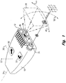
- Fig. 1 is a perspective view of a hand-holdable device that enables attitude tracking of the device, in accordance with the invention.
- Fig. 2 is a block diagram of components for controlling a screen cursor in accordance with the invention.
- Fig. 3 is a block diagram of an array of photosensors and transfer amplifiers of the correlator of Fig. 2.
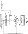
- Fig. 4 is an operation view of the steps for correlating successive images in accordance with the invention.
- Fig. 5 is a conceptual view of the steps of Fig. 4.
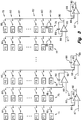
- Fig. 6 is an embodiment of a computation cell of an array of cells for carrying out the steps of Fig. 4.
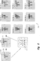
- Figs. 7-11 illustrate arrays of photosensors and computation cells for demonstrating and then reducing curvilinear distortions.
- a hand-holdable controller device 10 is shown as including an integrated circuit package 12 for acquiring and processing image data.
- an optoelectric integrated circuit chip 14 On the surface of the package is an optoelectric integrated circuit chip 14 having a two-dimensional array 16 of photosensors and having processing circuitry 18.
- the array and processing circuitry are used to acquire successive frames of image data, permitting the attitude of the device to be tracked.
- angular displacement about a horizontal axis 20, i.e. pitch, and angular displacement about a vertical axis 22, i.e. yaw can be determined.
- roll about the longitudinal axis 24 of the device 10 can also be monitored.
- the invention will be described primarily with reference to providing control of a remote element, such as controlling a screen cursor of a video display. However, it is understood that the approach of tracking attitude by means of correlating images formed by a photosensor array attached to the device has applications beyond that of controlling a screen cursor or the like.
- the sensor array 16 and the processing circuitry 18 are mounted on the front of the controller device 10 with the array facing outwardly.
- a lens 26 is shown in Fig. 1 as being partially cutaway in order to expose the array and circuitry.
- the lens may be an inexpensive plastic lens that is molded to the integrated circuit package 12.
- the focus of the lens is set nominally at infinity.
- the lens provides an image of a region of the surrounding environment to the sensor array 16.
- a short focal-length lens is preferred, since a greater number of features within the environment will be imaged and used for the purpose of tracking attitude.
- the image quality demands are sufficiently lax, such that the demands on the optical arrangement are not stringent. In fact, a slight blurring is desirable, so that the spatial frequencies of the image are coarser than the size of the array elements.
- the width of the field of view for imaging the environment is a matter of balancing the desire of capturing as much visible detail as possible with the requirement of avoiding excessive distortion.
- a 64° field of view provides a reasonable compromise between these two concerns.
- the dashed lines 28 in Fig. 1 represent the field of view for the sensor array 16.
- the arrangement of the optics and the sensor array may be selected to reduce any adverse effects of curvilinear distortion on the attitude-tracking approach of the invention.
- the optic/sensor arrangement will be described in greater detail below.
- a cursor control key 30 and a return key 32 On the top surface of the controller device 10 are a cursor control key 30 and a return key 32.
- the screen cursor of a video display may be captured by depression of the control key 30.
- the control key With the control key in a depressed position, the angular displacement of the device 10 will be translated into movement of the cursor along the display screen.
- key 30 is depressed and pitch and/or yaw of the device 10 is employed to drag the screen cursor to the desired movie.
- the control key 30 is then released to release control of the screen cursor.
- the return key 32 is depressed to activate the selection.
- a single selection key similar in operation to that of a computer mouse may be utilized, so that cursor control is continuously enabled.
- Remote communication is provided by infrared transmission via an emitter 34.
- Infrared emission is well known in the art.
- signal vectors are generated and transmitted. The vectors are sent as increments in order to reduce the burden of the IR communications channel by keeping the data bytes shorter.
- the rate at which vectors are transmitted should be sufficiently fast to achieve the necessary cursor responsiveness, but not so fast as to tax the limited bandwidth of the IR link to the controlled set.
- the transmission is a 10-bit word that is emitted every 40 ms, as needed. When neither of the keys 30 and 32 is depressed, no transmission occurs. This frees the IR emitter for other functions during non-cursor events.
- the controller device 10 may include keys to control other events, such as the changing of a television channel.
- a control clock 36 determines the timing of operations for the controller device 10.
- the image-capture rate is at least partially determined by the features that are to be imaged. Where the field of view 28 is a living room of a person engaged in operation of an ITV system, the image capture rate must be sufficiently great to ensure that the image data is sufficiently intelligible to permit correlation between successive images.
- the circuitry of Fig. 2 includes an exposure control 38 which shows a minimum exposure of 5 ⁇ s and a maximum exposure of 5 ms. Electronically, the "exposure time" is the interval during which charge generated by the individual photosensors is allowed to integrate during the 5 ms period between successive image captures.
- the exposure control 38 may be manually adjusted, the preferred embodiment is one in which there is a feedback line 40 from image correlator circuitry 42 to establish automatic gain control.
- the exposure control 38 increases the interval for integrating charge by the photosensors.
- the field of view 28 is contemplated to be approximately 64°.
- a single pixel will have an approximately 2° field of view (64°/32 pixels).
- correlations are limited to nearest-neighbor pixel cells. This establishes a maximum velocity for movement of the controller device 12.
- the maximum velocity should not exceed one pixel length between successive image captures. If a frame of image data is to be acquired at the correlator 42 every 5 ms, the maximum velocity will be 200 pixels per second. Since the field of view of each pixel is 2°, the maximum velocity is 400° per second.
- the operation of the correlator 42 will be explained in detail below. Its basic function is to compare the arrangement of pixel values in a first frame of image data to the location of a similar arrangement in a subsequent frame.
- the sensor array 16 is used to acquire a frame of 32x32 pixel values.
- the first captured frame is referred to as a reference frame.
- the first reference frame is captured upon depression of the cursor control key 30 of Fig. 1.
- a subsequently captured frame of pixel values referred to as a sample frame, is compared with the reference frame to detect changes in attitude of the controller device 10.
- a new reference frame is then acquired.
- the reference frame may be replaced by the sample frame after each correlation. Alternatively, the reference frame may be replaced with a sample frame each time a threshold is reached, such as a time threshold or a threshold based upon movement of the device.
- the process may be considered as fixing the two-dimensional reference frame in position and shifting a transparency of the two-dimensional sample frame to various positions atop the reference frame in order to detect alignment of common features of the two frames.
- This conceptual view is shown in Fig. 5 and is computationally carried out by an array of cells such as the pixel cell shown in Fig. 6.
- the correlation processing generates an attitudinal signal indicative of any changes in angular orientation of the controller device 10.
- the correlator 42 is shown as generating a signal in which change along the X axis is +0.75 pixels, while the change along the Y axis is -0.31 pixels.
- positive movement along the X axis may be indicated as a result of angular displacement of the device 10 such that the field of view 28 is moved in the direction of arrow 44, while a negative movement along the X axis is one in which a component of displacement of the field of view 28 is in the direction indicated by arrow 46.
- a positive value at the attitudinal signal indicates manipulation of the device 10 to rotate the field of view as shown by arrow 48, while a negative value of ⁇ Y indicates displacement in the direction shown by arrow 50.
- the preferred approach for operation of the correlator 42 is one in which nearest-neighbor pixel shifts are executed in order to track changes in attitude of the controller device. This approach will be detailed when referring to Figs. 4, 5 and 6. However, the attitude tracking alternatively may be carried out using correlations requiring shifts of greater than a single pixel. For either approach, interpolations are computationally performed to identify fractional pixel values. Such image correlating interpolating is well understood by persons skilled in the art.
- the output from the correlator 42 is received at a multiplier 52 that increases the sensitivity of the cursor control.
- the multiplier doubles the ⁇ X and ⁇ Y values from the correlator.
- the signal is then conducted to an accumulator 54.
- a divide-by-eight circuit 56 dictates operation of the accumulator 54.
- Eight samples will be received from the multiplier 52 before the accumulator outputs a sample to a modulo function block 58.
- the output of the modulo block will be the integer portion of the accumulation of the eight samples from the multiplier 52.
- the controller device transmits a cursor control signal by means of an IR emitter 34. IR transmission links have limited bandwidth.
- the use of the accumulator 54 reduces the demands on the communications link.
- the modulo block 58 passes only the whole numbers to a pulse code modulator 60.
- Each of the ⁇ X and ⁇ Y values is contained within 5 bits, with 4 bits relating to the numerical value and the remaining bit relating to whether the numerical value is positive or negative.
- the values output from the modulo block 58 to the modulator 60 are whole number values, while the remainder of the sample from the accumulator 54 is conducted to a residue circuit 62.
- the residue values are saved at the residue circuit and added to subsequent values from the accumulator.
- a 10-bit word is output from the pulse code modulator 60 to an amplifier 64 every 40 ms.
- the IR transmission from the emitter 34 is only 25 words per second.
- the IR transmission is received by a sensor 66 of a display system, such as a RIVS.
- the signal from the IR sensor 66 is decoded at a demodulator 68 and transmitted to a cursor control circuit 70 for manipulating a screen cursor of a video screen 72.
- the arrangement and interaction of the components of Fig. 2 permit cursor control based upon tracking of the attitude of the controller device 10 of Fig. 1.
- the controller encodes the device pitch, yaw and optionally roll by tracking the apparent motion of an image of the environment in which the device resides. It is not necessary to point the controller in any one direction, other than to establish the IR link between the emitter 34 and the sensor 66.
- the individual components of Fig. 2 are readily understood by persons skilled in the art and need not be explained in detail. However, the preferred embodiment of the correlator 42 will be set forth below.
- the preferred arrangement of the two-dimensional sensor array 16 and the optics 26 will also be set forth.
- the embodiment of Figs. 1 and 2 includes a sensor array 16 having thirty-two columns and thirty-two rows of photosensors.
- a sensor array 16 having thirty-two columns and thirty-two rows of photosensors.
- five columns 74, 75, 76, 77 and 78 of the thirty-two columns of photosensors are shown.
- Each column is operatively associated with a separate transfer amplifier 85.
- a photosensor in a column is connected to the operatively associated transfer amplifier for closing a read switch 86. In the operation of the circuitry of Fig. 3, no two photosensors are connected to the same transfer amplifier simultaneously.
- Each transfer amplifier 85 includes an input 87 that is connected to a source of a fixed voltage.
- a second input 88 is capacitively connected to the output 90 of the transfer amplifier by a transfer capacitor 89.
- the read switches 86 of the first row 79 of photosensors may be closed, so that each transfer capacitor 89 receives a charge corresponding to the light energy at the associated photosensor in the first row.
- the transfer amplifiers 85 and the transfer capacitors 89 function as integrators.
- the received charge is transferred to subsequent processing circuitry via the output lines 90.
- the read switches of the first row are opened and the transfer amplifiers are reset.
- the read switches of the second row 80 are then closed in order to transfer the signals from the photosensors of the second row. The process is repeated until each row of photosensors is read.
- the transfer amplifiers 85 photosensor signals are transferred in a row-by-row fashion to subsequent circuitry.
- Fig. 4 illustrates steps for carrying out the correlation processing for tracking attitude of a device.
- the correlations compare the positions of imaged features in successive frames to provide information related to changes in angular orientation during time intervals between frames.
- a reference frame is acquired.
- the capture of the reference frame may be initiated by depression of the cursor control key 30 on the upper surface of the device 10 of Fig. 1.
- the row-by-row transfer of signals from the photosensors continues until each photosensor in the array 16 has been read.
- a reference frame 202 is shown as having an image of a T-shaped feature 204.
- the image feature may be a window in a room of a person operating an ITV system.
- the sensor array 16 of Figs. 1-3 is used to acquire a sample frame 206 as shown in Fig. 5.
- the field of view 28 of the controller device during acquisition of the sample frame largely overlaps the field of view at the time of acquiring the reference frame 202.
- the imaged feature 204 e.g. a window, is included within both of the frames.
- the duration dt and the velocity of the movement of the device preferably are such that the common features 204 will move less than one pixel from the reference frame to the sample frame.
- the schematic representation of Fig. 5 shows the feature as having shifted upwardly and to the right by one full pixel. The full-pixel shift is assumed only to simplify the representation.
- Fig. 4 shows the step 208 of acquiring the sample frame after the step 200 of acquiring the reference frame.
- a computation step 210 is then executed.
- the correlation step is a shifting of the arrangement of the pixel values of the sample frame 204 and two nearest-neighbor pixel cells. The shifting is performed sequentially for each of eight nearest-neighbor pixel cells, as represented by member 212 in Fig. 5. Referring to the member 212, step “0" does not include a shift of the pixel values in the sample frame 206, step “1” is a diagonal shift upwardly and to the left, step “2" is an upward shift of the pixel values of the sample frame, etc.
- Eight shifts of the reference frame represented by member 212 occur one at a time, but all pixel values are shifted uniformly. In this manner, the eight pixel-shifted sample frames can be combined with the reference frame 202 to produce the frame array 214 of position frames.
- the position frame designated as "Position 0" does not include a shift, so that the result is merely a combination of frames 202 and 206.
- Correlations are used to find the locations of common features 204 of successive frames 202 and 206 in order to track the angular orientation of the controller device 10. Summing or integrating angular displacements from frame-to-frame allows an attitudinal signal to be generated for controlling a screen cursor.
- step 216 After the correlation step 210 has been executed for the sample frame acquired at step 208, a determination is made at step 216 as to whether to maintain or replace the reference frame. In some embodiments, the reference frame is not replaced. If the same reference frame is to be used for subsequent correlation computation, the process returns to step 208 and a new sample frame is acquired. On the other hand, for applications in which there is a substitution of reference frames, step 218 shows the use of the previously acquired sample frame as a new reference frame prior to returning to step 208 of acquiring a new sample frame.
- the reference frame can be shifted upon detection that common features have traveled more than one pixel length since the acquisition of the reference frame.
- the reference frame is "walked" by detection of pitch, yaw and/or roll of the device. This process provides a high degree of correlation match, but errors that do occur will accumulate if the reference frame is not periodically replaced.
- step 218 is included so as to place a restriction on the growth rate of this "random walk" error.
- Fig. 6 is a schematic diagram of an individual pixel cell, or computation cell 94, for implementing the nearest-neighbor shifts of member 212 in Fig. 5 and for carrying out the various steps of Fig. 4.
- Fig. 6 is a schematic diagram of an individual pixel cell, or computation cell 94, for implementing the nearest-neighbor shifts of member 212 in Fig. 5 and for carrying out the various steps of Fig. 4.
- other circuits may be used to carry out the process steps described and illustrated with reference to Figs. 4 and 5.
- the computation cell 94 of Fig. 6 is one of an array of computation cells. If there is a one-to-one correspondence of computation cells and photosensors, the embodiment of Figs. 1-3 will have 1,024 computation cells. For the reference frame, the pixel value from the photosensor that corresponds to the particular cell 94 will be stored at the REFDATA node 148, while pixel values of the sample frame will be stored at NN(0) node 108.
- the shifted sample frames for forming the frame array 214 of Fig. 5 are provided by changing the signal connections to NNINPUT input 150 of a square-of-the-difference circuit 146. The output 150 of the circuit 146 is combined with the outputs of the other 1,023 computation cells to track the attitude of the controller device 10.
- Image data WDATA(i) is received from the photosensor that corresponds to the computation cell 94 at line 96, by means of a charge compensate transistor switch 98 under the control of a WR(j) signal. After the WR(j) signal is deasserted, the new data is held at capacitor 100 and is buffered by an amplifier 102. In the entire array of 1,024 computation cells, the array of CDATA nodes 104 is collectively referred to as the "reference frame" or the “sample frame,” depending upon the timing of the process. Control input CDOUT 106 selects signal CDATA, comparison data, or selects REFOUT for the nearest-neighbor output node NN(0) 108.
- the nearest-neighbor inputs NN(0)-NN(8) 110, 112, 114, 116, 118, 120, 122, 124 and 126 are separately selected by means of switch control signals S(0)-S(8) on lines 128.
- the NN(0)-NN(8) inputs 110-126 are the outputs of the nearest-neighbor cells according to the data cell map 212 of Fig. 5.
- the switch control signals are generated by a 4-9 encoder, not shown, that is external to the computational array.
- the 4-bit input to the encoder is referred to as the nearest-neighbor address and takes on binary values from 0000(0) to 1000(8).
- NNINPUT nearest-neighbor input node 130
- REFLD 132 The nearest-neighbor input node 130
- REFDATA 136 can be sampled and held on REFSH 138 by pulsing REFSFT 140.
- ROWTSTB 142 can be asserted, allowing the NN(0) signal to propagate to the TEST output 144.
- the TEST signals from each cell in a row of cells connect to common vertical buses in each column of the computational array and are multiplexed at the bottom of the array and driven off-chip.
- a standard row decoder along the left edge of the array allows selection of a particular row for test.
- the test feature is not critical to the invention.
- Each computation cell 94 has a circuit 146 that determines correlation values.
- a first input 148 receives the reference data from REFDATA node 136.
- a second input 150 provides the nearest-neighbor input NNINPUT selected by the appropriate switch control signal at lines 128.
- the output 152 of the correlation cell is a current. All of the correlation outputs in the computational array are summed together in a single off-chip summing resistor of a tracking circuit 154. The voltage developed across the summing resistor is referred to as the correlation values in Fig. 4.
- the circuit 146 is based on a squared-difference calculation.
- the cell 94 may be modified to provide product-based correlations without modifying the basic architecture of the array.
- Control inputs S(0)-S(8), REFLD, REFSFT and CDOUT are global to the entire array, so that the sample frame is manipulated and shifted uniformly within the computation cell array.
- Location 0 of an image refers to the present location of the image.
- the representation is that the image data in all of the cells of the array are moved to the neighbor cell that is to the left and upward. That is, the movement is relevant to a single cell in the array and is relevant to every cell in the array.
- the computational array functionality can be best described in terms of four basic operations: image acquisition, reference image load, correlation computation, and reference image translation.
- image acquisition refers to the loading of new image data via the WDATA line 96 of each computation cell 94.
- every 50 ms a new frame of pixel values is acquired from the sensor array via the column transfer amplifiers.
- the process of loading a new reference image is referred to as a "frame transfer.”
- the operations of the computation array described below are coordinated with the frame transfer process by observing and synchronizing with a frame transfer (FTB) signal.
- FTB frame transfer
- the validity of a new sample image is signaled by the falling edge of the FTB signal.
- the operations described below are only appropriate when FTB is not asserted.
- Loading a reference frame of pixel values is required before any image correlations can be calculated.
- all of the voltages at the CDATA nodes 104 in the computational array must be transferred to the REFH nodes 134. This is accomplished by setting CDOUT 106 and S(0) high, and pulsing the REFLD signal on line 132.
- the reference frame can also be loaded from another nearest-neighbor location by asserting one of the S(1)-S(8) inputs instead of S(0).
- Amplifier 156 buffers the REFH node 134 from the REFDATA nodes 136.
- the two-dimensional array of REFDATA nodes 136 within the computational array are collectively known as the reference frame.
- the computational array After a reference frame has been loaded, the computational array is ready to compute correlations. Correlations between the reference frame of pixel values and the subsequent sample frame are computed by setting the nearest-neighbor address to the desired value and recording the resulting voltage developed across the summing resistor of the attitude tracking circuit 154. When the sensor array has moved a single pixel distance from the location at which the reference frame was acquired, a strong correlation will be detected at one of the nearest-neighbor locations. In Fig. 5, the correlation is detected to be at POSITION 7 in the array 214. Sub-pixel movements can be determined by interpolating in two-dimensional correlation space.
- correlations between the reference frame and itself can be computed by setting CDOUT 106 low and pulsing REFSFT 140. This causes the nearest-neighbor inputs to come from the reference frame, rather than from the sample frame.
- Fig. 4 referred to the step 218 of replacing the reference frame.
- the same reference frame may be used for multiple pixel movements by allowing the reference to "reach" beyond the nearest-neighbor cells.
- the reference frame Upon detection that changes in the angular orientation of the device have caused the field of view to shift by more than one pixel distance, the reference frame is shifted to the new location within the computational array. The shift to the new location is dictated by the change in angular orientation of the device.
- nearest-neighbor correlations become correlations between the translated reference frame and a newly acquired sample frame.
- a first step is to pulse REFSFT 140 high to sample-and-hold the REFDATA signal 136 at REFSH 138.
- a third buffer amplifier 158 drives REFOUT 160 with the REFSH signal.
- CDOUT 106 is driven low, allowing REFOUT 160 to be the output of the computation cell 94 at the NN(0) node 108.
- the nearest-neighbor address is then set to select the appropriate S(0)-S(8) input from the switch control signal lines 128. For example, if the T-shaped feature 204 in Fig. 5 is detected to have moved to the right and upwardly from the time at which the reference frame 202 is acquired to the time at which the sample frame 204 is acquired, the pixel values that comprise the reference frame must be shifted from cell-to-cell to the right and upwardly. Since S(0)-S(8) signals switch the address of the cell input NNINPUT 130, S(7) must be driven high to enable movement of the pixel value from location 7 of 212 in Fig. 5 to location 0. This takes place in each computation cell of the computational array.
- REFLD 132 is pulsed high to sample-and-hold the translated reference values at REFH 134. After this operation has occurred in each of the computation cells of the array, the computational array is again ready to compute correlations.
- Another aspect of the invention is the arrangement for significantly reducing the adverse effects of what is known in lens design as “curvilinear distortions.” These distortions are also referred to as pincushion, barrel, and perspective distortions. The distortions compress rectilinear detail at the outer edges of a field of view
- the curvilinear distortions are particularly pronounced in simple lenses with wide fields of view. Such a lens may be used as the lens 26 in Fig. 1.
- the distortions are problematic, since they will cause the apparent shape of a feature to change as the feature drifts across the field of view. A change in the apparent shape of a feature will adversely affect the correlation process described with reference to Figs. 4-6.
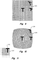
- Fig. 7 shows images of a T-shaped feature, imaged with distortion-free optics onto a 32x32 pixel array 220. With such optics, the shape of the feature does not change with travel across the array, allowing high quality correlations and accurate tracking of pitch and yaw.
- Fig. 8 illustrates the same feature imaged onto a pixel array 222 using a simple lens. It can be seen that the distortion increases as the feature is moved further from the optical axis of the lens.
- Fig. 9 shows in a stylized manner the way in which the feature is interpreted by the computational array for performing the correlation processing of Fig. 5.
- Each pixel in the array 224 of Fig. 9 represents a computational cell 94, such as the one shown in Fig. 6. It is evident that the feature is "viewed" differently as it changes position within the computational array. This reduces the quality of the correlation, and the accuracy of the tracking of device attitude. Equally undesirable, the apparent motion of the feature changes with position, further degrading the accuracy of attitude tracking.
- Fig. 10 illustrates a two-dimensional array 226 of photosensors configured to match the distortion of the lens. That is, the characteristics of the lens system with regard to introducing curvilinear distortions are determined and the array is configured to compensate for the distortions. Projected onto the curvilinear array of Fig. 10 is the T-shaped feature in three different positions. It can be noted that although the images of the feature are still distorted, the distortion causes the images to fit within the pixels. Thus, each feature will be viewed as being rectilinear at the computation array level. That is, the corner image 228 will be distorted at the sensor level, as shown in Fig. 10, but the corner image 230 will be "viewed” as being an undistorted "T” at the computational array 232 of Fig. 11.
- the method of ascertaining the curvilinear geometry of the photosensor array elements may now be described.
- it consists of starting with an enlarged object plot of a 32x32 array of rectilinear (not curvilinear) cells, perhaps a foot square.
- the lens of choice is next used to produce an image of this array. This small and curvilinear image captures the distortions of the lens, and represents a reasonable approximation to an ideal array geometry.
- This process produces accurate imaging with lenses of any field of view, and has many applications such as in positional navigation.
- it is a goal to transduce angles and not distances. For lenses of narrow fields of view, angles tend to become increasingly compressed as one moves further off of the optical axis.
- This undesirable angular compression is avoided by changing the design process such that a segment of a sphere is substituted for the aforementioned flat array.
- the center of the spherical segment is overlaid approximately with the nodal point of the lens.
- the segment is lined at intervals of perhaps 2° in latitude and longitude.
- Each cell formed on the spherical segment, once imaged and reduced, is taken to be the outline of an array cell.
- curvilinear array provides more accurate autocorrelations, regardless of how far the images move from the axis of the sensor array.
- a second benefit is that distances are true and not compressed, so that attitude tracking is accurate over larger pixel moves without regard to where the move is imaged on the sensor array.
- Each benefit of the curvilinear array in itself contributes to more accurate tracking. Since the correlation is stronger and less noisy, the accuracy of measuring the end point of each move segment is higher. Moreover, since the image can be tracked in longer segments, the frequency of zeroing the reference frame is reduced, so that the cumulative re-zeroing error becomes less. Finally, because the curvilinear array does not compress off-axis moves, the accuracy of distance measurement is greater.
Abstract
Description
- The invention relates generally to methods and systems for tracking attitude of a device and more particularly to tracking the attitude of a device in order to control a device or process, such as a cursor of a video display.
- There are applications in which video systems require that a person interact with information presented on a display screen. At times, the interaction is to occur while the person is situated at a distance from the display screen. As will be described more fully below, the interaction may be accomplished by remotely controlling a screen cursor in one of a variety of manners. The interactions may include selecting from a variety of choices presented as a screen menu, or "typing" text using an on-screen keyboard. Examples of remote interactive video systems (RIVS) include interactive television (ITV), TV-style Internet browsers, and conference-room video projectors.
- One key component of a RIVS is the "pointing" device for controlling the on-screen cursor. The pointing device fulfills a function analogous to that which mice, trackballs, and graphic tablets perform for computers. However, the environment for RIVS presents difficulties that are typically not encountered in operation of a computer. For example, an operator of a RIVS is typically further away from the controlled device than is the operator of a computer. As another example, the operator of a RIVS is more likely to be in an unstructured immediate environment, e.g., an ITV operator seated across a living room from a television set. In many situations, the environment precludes use of conventional computer pointing devices, such as mice. Moreover, a RIVS is rarely equipped with a keyboard, so that the pointing device may have to accommodate the extra burden of providing a text entry.
- There are a number of known pointing devices for a RIVS. Most of the known pointing devices implement some variation of a four-key cursor pad on a hand-held controller. The four-key cursor pad is manipulated to step the screen cursor up, down, left or right among various menu choices. Such interfaces emulate the computer keyboard cursor keys used with old-style textural interfaces. However, these interfaces are typically much slower and less intuitive to use than computer mice and other pointing devices developed for modern graphical software interfaces.
- In an effort to improve upon cursor control within the RIVS environment, more advanced computer pointing devices of mice and trackballs have been adapted. In one adaptation, a miniature trackball is mounted atop a controller, with the trackball being operated by the person's thumb. The trackball controller is faster than the use of cursor keys and facilitates diagonal moves. Unfortunately, the trackball may require repeated strokes to accomplish large cursor movements and, in general, thumb control taxes the user's thumb dexterity. For example, it is difficult to trace the cursor in a circle on the display screen.
- The use of a mouse for ITV cursor control has been demonstrated. The advantage of the mouse is that it provides excellent and intuitive cursor control. The concern is that there may not be a suitable planar operating surface that is convenient to the operator.
- A further refinement in the RIVS pointing art is the use of devices that enable control of a cursor by merely gesturing with a controller. These devices may measure the attitude, i.e. pitch, yaw, and possibly roll, of the controller. A first category of such an approach employs light beams to measure attitude. PCT International Publication Number WO 95/19031 describes a system for determining the pointing orientation of a remote unit relative to a fixed base unit. The fixed base unit includes one or more light sources for emitting a light beam. The emitted light is polarized in at least one predetermined orientation. The movable remote unit includes a photodetector for detecting the polarized emitted light. The attitude of the movable remote unit may be determined by measuring the intensity of received light from various directions.
- Another implementation of the emitted-light category of measuring attitude is one in which an infrared (IR) signal is beamed from the area of the video display. The IR signal is defocused and is imaged onto a quad photodiode array in the controller. The relative signal amplitudes from the four photodiodes may be used to determine the relative orientation of the controller to a line drawn from the display. One concern is that the system may undesirably flood the room with intense IR, rendering other nearby IR-coupled appliances (e.g., a VCR controller) inoperative. A second concern is that the limited range of transmission of defocused IR signals may render this system of measuring attitude unreliable when the controller is more than a relatively short distance from the video display.
- A second category of devices that measure attitude of the controller is one in which inertial navigation principles are employed. Gyroscopes or encoded gimballed masses establish inertial frames in the controllers, against which attitude changes can be measured. The attitude information may then be transmitted to the video display via a radio-frequency link to a small dipole antenna affixed atop the video display.
- The third category is related to the first category. A hand-held object that provides cursor control has a number of light sources mounted on one surface. A single electronic camera is directed to capture images of the light Sources mounted on a hand-held object. Locations of the images of the light sources are detected in each camera image, and a computer is used to determine the attitude of the light-emitting hand-held object. Such a device is described in U.S. Pat. No. 5,338,059 to DeMenphon.
- A closely related need exists in the field of virtual reality. In games, simulations, and other visualization situations, it is often necessary to encode the attitude of a user's head, or other body part. In many cases, systems for encoding head pitch and yaw may be applied to RIVS controllers, and vice versa. One known virtual reality system encodes pitch and yaw by means of instrumented compasses and gravimeters.
- While the known cursor control devices and attitude-determining systems operate adequately for their intended purposes, each is associated with a concern or a problem. Operation may be slow or tedious, or may require use of a specific operating surface. Devices and systems that include IR radiation may adversely affect operation of other devices. Attitude-sensing devices that are based on gravity may have difficulty in distinguishing tilting from transverse acceleration, thereby rendering control erratic. This last problem conceivably could be solved by gyro stabilization, but the cost and power consumption make this solution unattractive. Known systems that utilize light detection require adding a second contrivance at the display, again adding additional cost.
- What is needed is a method and a system for reliably tracking attitude of a device. What is further needed is such a method and system that is cost efficient when used in controlling a screen cursor or when used in other remote interactive video applications.
- Correlation of successive images acquired by means of a two-dimensional array of photosensors is used as a basis for tracking attitude of a device to which the array is affixed. In the preferred embodiment, the device is a hand-holdable member, such as a controller for maneuvering a cursor on a display screen of a video set. Based upon the step of correlating images to detect differences in location of imaged features that are common to a succession of images, the system generates an attitudinal signal indicative of any changes in angular orientation during the time period of acquiring the images. That is, the attitudinal signal is determined by the pitch and yaw, and optionally the roll, of the device that bears the array of photosensors. Since the acquired images need not be related to that which is being controlled, e.g. a screen cursor, the device can face in any direction during the control process. Moreover, it is not necessary to provide a dimensional one-to-one correspondence of angular displacement of the device and travel of that which is being controlled. Within cursor control, for example, the controller may be directed arbitrarily and relationships of degrees of pitch and yaw to lengths of cursor movement may be user-adjustable.
- The two-dimensional array of photosensors is used to acquire a reference frame for tracking the attitude of the device. The reference frame is stored and a second image of features within a field of view of the array is acquired. The second image may be considered to be a sample image, and the fields of view of the two images should be largely overlapping, so that the reference and sample frames include a number of common features. While not critical, the device includes optics which provide a focus nominally at infinity, intentionally presenting an off-sharp image to the array of photosensors. In the application of the device for controlling a screen cursor, the representative imaged features will typically include windows, lamps, furniture and the display screen itself. In any application of the invention, one or more stationary sources of light may be specifically added within the environment to be imaged, so that successive images of the fixed light are used for the purpose of correlation. In one implementation of such an embodiment, the source of light is an IR emitter and the imaging array on the device is provided with IR filtering to permit tracking of the attitude of the device.
- Conceptually, the step of correlating the reference frame with a sample frame is one in which one of the frames is fixed in position and the other frame is repeatedly shifted to determine which shifted position best approximates an alignment of the imaged features that are common to the two frames, thereby allowing the determination of the pitch and yaw of the imaging array during the interval between acquiring the two frames. In practice, the shifts are performed computationally and are shifts of pixel values in which each pixel value is indicative of light energy received at a particular photosensor at a specific time. The correlations may be limited to computational shifts of only one pixel for nearest-neighbor correlations, or may be multi-pixel computational shifts. The nearest-neighbor correlation process is often preferred, since it is less computationally complex, with only the original position and eight computational shifts being necessary. Interpolations are then performed to determine angular displacements that are less than a full pixel. Angular displacement of the device about a horizontal axis, i.e. pitch, will result in the arrangement of pixel values of the reference frame being moved upwardly or downwardly. Angular displacement of the device about a vertical axis, i.e. yaw, will result in the pixel value arrangement being moved to the left or to the right. The system detects pitch, yaw and combinations of pitch and yaw. The attitudinal signal that is generated by the system is responsive to the detection of such angular displacements. Optionally, roll may also be considered.
- In the application in which the attitudinal signal is generated in order to control a screen cursor, the device preferably includes a transmitter for wireless transmission of a cursor-control signal. For example, the signal may be transmitted via an infrared beam. Changes in the pitch of the hand-holdable device are then translated into vertical movements of the screen cursor, while changes in device yaw will move the screen cursor laterally. In this embodiment, translational movement of the device may also be detected and utilized, so that vertical or horizontal movement of the device translates to a corresponding vertical or horizontal movement of the screen cursor.
- One concern in the implementation of the method and system is the effect of the phenomena known in the lens design as curvilinear distortions. Curvilinear distortions are also referred to as pin-cushion, barrel, and perspective distortions. Rectilinear detail is compressed at the outer edges of the field by such distortion. Curvilinear distortion is particularly pronounced in simple lenses with wide fields of view, such as the lens contemplated for use with the present invention. In the invention, the field of view is preferably approximately 64°, so that curvilinear distortions will inevitably occur.
- In the preferred embodiment, the photosensors of the array vary dimensionally in order to define an array that is curvilinear, i.e., includes an arcuate outer edge. The curvilinear array is dimensioned to compensate for the curvilinear distortion introduced by the lens system. The imaging by the optics is evaluated to characterize the curvilinear distortion, with the array then being patterned to offset the distortion. In this manner, the arrangement of the photosensor array and the optics greatly reduces adverse effects of curvilinear distortion.
- An advantage of the invention is that device attitude may be tracked in a reliable and cost-efficient manner. For those applications in which the array-bearing device is a hand-holdable device, control of a screen cursor or the like is economically achieved without a premium on dexterity. Moreover, the device does not require operation on a suitable surface.
- Fig. 1 is a perspective view of a hand-holdable device that enables attitude tracking of the device, in accordance with the invention.
- Fig. 2 is a block diagram of components for controlling a screen cursor in accordance with the invention.
- Fig. 3 is a block diagram of an array of photosensors and transfer amplifiers of the correlator of Fig. 2.
- Fig. 4 is an operation view of the steps for correlating successive images in accordance with the invention.
- Fig. 5 is a conceptual view of the steps of Fig. 4.
- Fig. 6 is an embodiment of a computation cell of an array of cells for carrying out the steps of Fig. 4.
- Figs. 7-11 illustrate arrays of photosensors and computation cells for demonstrating and then reducing curvilinear distortions.
- With reference to Fig. 1, a hand-
holdable controller device 10 is shown as including an integratedcircuit package 12 for acquiring and processing image data. On the surface of the package is an optoelectricintegrated circuit chip 14 having a two-dimensional array 16 of photosensors and havingprocessing circuitry 18. The array and processing circuitry are used to acquire successive frames of image data, permitting the attitude of the device to be tracked. Thus, angular displacement about ahorizontal axis 20, i.e. pitch, and angular displacement about a vertical axis 22, i.e. yaw, can be determined. Optionally, roll about thelongitudinal axis 24 of thedevice 10 can also be monitored. - The invention will be described primarily with reference to providing control of a remote element, such as controlling a screen cursor of a video display. However, it is understood that the approach of tracking attitude by means of correlating images formed by a photosensor array attached to the device has applications beyond that of controlling a screen cursor or the like.
- The
sensor array 16 and theprocessing circuitry 18 are mounted on the front of thecontroller device 10 with the array facing outwardly. Alens 26 is shown in Fig. 1 as being partially cutaway in order to expose the array and circuitry. The lens may be an inexpensive plastic lens that is molded to theintegrated circuit package 12. The focus of the lens is set nominally at infinity. The lens provides an image of a region of the surrounding environment to thesensor array 16. A short focal-length lens is preferred, since a greater number of features within the environment will be imaged and used for the purpose of tracking attitude. The image quality demands are sufficiently lax, such that the demands on the optical arrangement are not stringent. In fact, a slight blurring is desirable, so that the spatial frequencies of the image are coarser than the size of the array elements. - The width of the field of view for imaging the environment is a matter of balancing the desire of capturing as much visible detail as possible with the requirement of avoiding excessive distortion. A 64° field of view provides a reasonable compromise between these two concerns. The dashed
lines 28 in Fig. 1 represent the field of view for thesensor array 16. The arrangement of the optics and the sensor array may be selected to reduce any adverse effects of curvilinear distortion on the attitude-tracking approach of the invention. The optic/sensor arrangement will be described in greater detail below. - On the top surface of the
controller device 10 are acursor control key 30 and areturn key 32. In operation, the screen cursor of a video display may be captured by depression of thecontrol key 30. With the control key in a depressed position, the angular displacement of thedevice 10 will be translated into movement of the cursor along the display screen. For example, in selecting a particular movie from a menu of movies presented by an interactive television system, key 30 is depressed and pitch and/or yaw of thedevice 10 is employed to drag the screen cursor to the desired movie. Thecontrol key 30 is then released to release control of the screen cursor. With the cursor indicating the desired menu choice, thereturn key 32 is depressed to activate the selection. Alternatively, a single selection key similar in operation to that of a computer mouse may be utilized, so that cursor control is continuously enabled. - Remote communication is provided by infrared transmission via an
emitter 34. Infrared emission is well known in the art. For cursor control, signal vectors are generated and transmitted. The vectors are sent as increments in order to reduce the burden of the IR communications channel by keeping the data bytes shorter. The rate at which vectors are transmitted should be sufficiently fast to achieve the necessary cursor responsiveness, but not so fast as to tax the limited bandwidth of the IR link to the controlled set. As will be explained more fully below, in one embodiment the transmission is a 10-bit word that is emitted every 40 ms, as needed. When neither of thekeys controller device 10 may include keys to control other events, such as the changing of a television channel. - Referring now to Figs. 1 and 2, a
control clock 36 determines the timing of operations for thecontroller device 10. The image-capture rate is at least partially determined by the features that are to be imaged. Where the field ofview 28 is a living room of a person engaged in operation of an ITV system, the image capture rate must be sufficiently great to ensure that the image data is sufficiently intelligible to permit correlation between successive images. The circuitry of Fig. 2 includes anexposure control 38 which shows a minimum exposure of 5 µs and a maximum exposure of 5 ms. Electronically, the "exposure time" is the interval during which charge generated by the individual photosensors is allowed to integrate during the 5 ms period between successive image captures. While the exposure control may be manually adjusted, the preferred embodiment is one in which there is afeedback line 40 fromimage correlator circuitry 42 to establish automatic gain control. Thus, if the image data is consistently off-scale for performing correlation processing, theexposure control 38 increases the interval for integrating charge by the photosensors. - As previously noted, the field of
view 28 is contemplated to be approximately 64°. In a sensor array of 32x32 photosensors, a single pixel will have an approximately 2° field of view (64°/32 pixels). In the preferred embodiment to be described below, correlations are limited to nearest-neighbor pixel cells. This establishes a maximum velocity for movement of thecontroller device 12. In the preferred embodiment, the maximum velocity should not exceed one pixel length between successive image captures. If a frame of image data is to be acquired at thecorrelator 42 every 5 ms, the maximum velocity will be 200 pixels per second. Since the field of view of each pixel is 2°, the maximum velocity is 400° per second. - The operation of the
correlator 42 will be explained in detail below. Its basic function is to compare the arrangement of pixel values in a first frame of image data to the location of a similar arrangement in a subsequent frame. Thesensor array 16 is used to acquire a frame of 32x32 pixel values. The first captured frame is referred to as a reference frame. The first reference frame is captured upon depression of thecursor control key 30 of Fig. 1. A subsequently captured frame of pixel values, referred to as a sample frame, is compared with the reference frame to detect changes in attitude of thecontroller device 10. A new reference frame is then acquired. The reference frame may be replaced by the sample frame after each correlation. Alternatively, the reference frame may be replaced with a sample frame each time a threshold is reached, such as a time threshold or a threshold based upon movement of the device. - Correlation will be described in detail below. Conceptually, the process may be considered as fixing the two-dimensional reference frame in position and shifting a transparency of the two-dimensional sample frame to various positions atop the reference frame in order to detect alignment of common features of the two frames. This conceptual view is shown in Fig. 5 and is computationally carried out by an array of cells such as the pixel cell shown in Fig. 6.
- The correlation processing generates an attitudinal signal indicative of any changes in angular orientation of the
controller device 10. In Fig. 2, thecorrelator 42 is shown as generating a signal in which change along the X axis is +0.75 pixels, while the change along the Y axis is -0.31 pixels. In Fig. 1, positive movement along the X axis may be indicated as a result of angular displacement of thedevice 10 such that the field ofview 28 is moved in the direction of arrow 44, while a negative movement along the X axis is one in which a component of displacement of the field ofview 28 is in the direction indicated by arrow 46. Regarding the Y axis, a positive value at the attitudinal signal indicates manipulation of thedevice 10 to rotate the field of view as shown by arrow 48, while a negative value of ΔY indicates displacement in the direction shown byarrow 50. - The preferred approach for operation of the
correlator 42 is one in which nearest-neighbor pixel shifts are executed in order to track changes in attitude of the controller device. This approach will be detailed when referring to Figs. 4, 5 and 6. However, the attitude tracking alternatively may be carried out using correlations requiring shifts of greater than a single pixel. For either approach, interpolations are computationally performed to identify fractional pixel values. Such image correlating interpolating is well understood by persons skilled in the art. - The output from the
correlator 42 is received at amultiplier 52 that increases the sensitivity of the cursor control. In the embodiment of Fig. 2, the multiplier doubles the ΔX and ΔY values from the correlator. The signal is then conducted to anaccumulator 54. A divide-by-eightcircuit 56 dictates operation of theaccumulator 54. Eight samples will be received from themultiplier 52 before the accumulator outputs a sample to amodulo function block 58. The output of the modulo block will be the integer portion of the accumulation of the eight samples from themultiplier 52. As previously noted, the controller device transmits a cursor control signal by means of anIR emitter 34. IR transmission links have limited bandwidth. The use of theaccumulator 54 reduces the demands on the communications link. - The exemplary sample from the
accumulator 54 in Fig. 2 is shown to be one in which ΔX = +15.2 pixels and ΔY = -3.3 pixels. The modulo block 58 passes only the whole numbers to apulse code modulator 60. Each of the ΔX and ΔY values is contained within 5 bits, with 4 bits relating to the numerical value and the remaining bit relating to whether the numerical value is positive or negative. - The values output from the
modulo block 58 to themodulator 60 are whole number values, while the remainder of the sample from theaccumulator 54 is conducted to aresidue circuit 62. The residue values are saved at the residue circuit and added to subsequent values from the accumulator. - The remaining arrangement of components is well known in the art. A 10-bit word is output from the
pulse code modulator 60 to anamplifier 64 every 40 ms. Thus, the IR transmission from theemitter 34 is only 25 words per second. The IR transmission is received by asensor 66 of a display system, such as a RIVS. The signal from theIR sensor 66 is decoded at ademodulator 68 and transmitted to acursor control circuit 70 for manipulating a screen cursor of avideo screen 72. Merely for example, the screen may have 64x64 cursor addresses and the screen cursor may move 15x25 = 375 address states/second. In the example given above in which the field ofview 28 of Fig. 1 is 64°, the screen can be traversed in 0.17 second (64/375). - The arrangement and interaction of the components of Fig. 2 permit cursor control based upon tracking of the attitude of the
controller device 10 of Fig. 1. The controller encodes the device pitch, yaw and optionally roll by tracking the apparent motion of an image of the environment in which the device resides. It is not necessary to point the controller in any one direction, other than to establish the IR link between theemitter 34 and thesensor 66. With the possible exception of thecorrelator 42, the individual components of Fig. 2 are readily understood by persons skilled in the art and need not be explained in detail. However, the preferred embodiment of thecorrelator 42 will be set forth below. The preferred arrangement of the two-dimensional sensor array 16 and theoptics 26 will also be set forth. - As previously noted, the embodiment of Figs. 1 and 2 includes a
sensor array 16 having thirty-two columns and thirty-two rows of photosensors. Referring now to Fig. 3, fivecolumns rows separate transfer amplifier 85. A photosensor in a column is connected to the operatively associated transfer amplifier for closing aread switch 86. In the operation of the circuitry of Fig. 3, no two photosensors are connected to the same transfer amplifier simultaneously. - Each
transfer amplifier 85 includes aninput 87 that is connected to a source of a fixed voltage. Asecond input 88 is capacitively connected to theoutput 90 of the transfer amplifier by atransfer capacitor 89. - In the operation of the circuit of Fig. 3, the read switches 86 of the
first row 79 of photosensors may be closed, so that eachtransfer capacitor 89 receives a charge corresponding to the light energy at the associated photosensor in the first row. Thus, thetransfer amplifiers 85 and thetransfer capacitors 89 function as integrators. The received charge is transferred to subsequent processing circuitry via the output lines 90. Following the readout of the first row, the read switches of the first row are opened and the transfer amplifiers are reset. The read switches of thesecond row 80 are then closed in order to transfer the signals from the photosensors of the second row. The process is repeated until each row of photosensors is read. By the operation of thetransfer amplifiers 85, photosensor signals are transferred in a row-by-row fashion to subsequent circuitry. - Fig. 4 illustrates steps for carrying out the correlation processing for tracking attitude of a device. In effect, the correlations compare the positions of imaged features in successive frames to provide information related to changes in angular orientation during time intervals between frames. In a
first step 200, a reference frame is acquired. As noted above, the capture of the reference frame may be initiated by depression of thecursor control key 30 on the upper surface of thedevice 10 of Fig. 1. The row-by-row transfer of signals from the photosensors continues until each photosensor in thearray 16 has been read. The reference frame is a frame of 1,024 pixel values (32x32 = 1,024). - While the tracking of the attitude of the
controller device 10 is performed computationally, the concepts of the correlation may be described with reference to Figs. 4 and 5. Areference frame 202 is shown as having an image of a T-shapedfeature 204. The image feature may be a window in a room of a person operating an ITV system. At a later time (dt) thesensor array 16 of Figs. 1-3 is used to acquire asample frame 206 as shown in Fig. 5. The field ofview 28 of the controller device during acquisition of the sample frame largely overlaps the field of view at the time of acquiring thereference frame 202. As a result, the imagedfeature 204, e.g. a window, is included within both of the frames. The duration dt and the velocity of the movement of the device preferably are such that thecommon features 204 will move less than one pixel from the reference frame to the sample frame. The schematic representation of Fig. 5 shows the feature as having shifted upwardly and to the right by one full pixel. The full-pixel shift is assumed only to simplify the representation. - Fig. 4 shows the
step 208 of acquiring the sample frame after thestep 200 of acquiring the reference frame. Acomputation step 210 is then executed. The correlation step is a shifting of the arrangement of the pixel values of thesample frame 204 and two nearest-neighbor pixel cells. The shifting is performed sequentially for each of eight nearest-neighbor pixel cells, as represented bymember 212 in Fig. 5. Referring to themember 212, step "0" does not include a shift of the pixel values in thesample frame 206, step "1" is a diagonal shift upwardly and to the left, step "2" is an upward shift of the pixel values of the sample frame, etc. Eight shifts of the reference frame represented bymember 212 occur one at a time, but all pixel values are shifted uniformly. In this manner, the eight pixel-shifted sample frames can be combined with thereference frame 202 to produce theframe array 214 of position frames. The position frame designated as "Position 0" does not include a shift, so that the result is merely a combination offrames - Within the
frame array 214, "Position 7" has the highest correlation. Based upon the correlation results, the position of the T-shapedfeature 204 in thesample frame 206 is determined to be an upward and rightward shift relative to the position of the same feature in the earlier-acquiredreference frame 202. The movement of the feature is a result of a combination of pitch and yaw of thecontroller device 10 of Fig. 1, with components indicated by the leftward arrow 44 and thedownward arrow 50. - While other correlation approaches may be employed, an acceptable approach is a "sum of the squared differences" correlation. For the embodiment of Figs. 4 and 5, there are nine correlation coefficients (Ck = C0, C1 ... C8) formed from the nine offsets of 212.
- Correlations are used to find the locations of
common features 204 ofsuccessive frames controller device 10. Summing or integrating angular displacements from frame-to-frame allows an attitudinal signal to be generated for controlling a screen cursor. - After the
correlation step 210 has been executed for the sample frame acquired atstep 208, a determination is made atstep 216 as to whether to maintain or replace the reference frame. In some embodiments, the reference frame is not replaced. If the same reference frame is to be used for subsequent correlation computation, the process returns to step 208 and a new sample frame is acquired. On the other hand, for applications in which there is a substitution of reference frames, step 218 shows the use of the previously acquired sample frame as a new reference frame prior to returning to step 208 of acquiring a new sample frame. - If the same reference frame is to be used throughout a process of dragging a cursor along a screen, the reference frame can be shifted upon detection that common features have traveled more than one pixel length since the acquisition of the reference frame. Thus, the reference frame is "walked" by detection of pitch, yaw and/or roll of the device. This process provides a high degree of correlation match, but errors that do occur will accumulate if the reference frame is not periodically replaced. Thus, in the
preferred embodiment step 218 is included so as to place a restriction on the growth rate of this "random walk" error. - Fig. 6 is a schematic diagram of an individual pixel cell, or
computation cell 94, for implementing the nearest-neighbor shifts ofmember 212 in Fig. 5 and for carrying out the various steps of Fig. 4. However, as will be understood by persons skilled in the art, other circuits may be used to carry out the process steps described and illustrated with reference to Figs. 4 and 5. - The
computation cell 94 of Fig. 6 is one of an array of computation cells. If there is a one-to-one correspondence of computation cells and photosensors, the embodiment of Figs. 1-3 will have 1,024 computation cells. For the reference frame, the pixel value from the photosensor that corresponds to theparticular cell 94 will be stored at theREFDATA node 148, while pixel values of the sample frame will be stored at NN(0)node 108. The shifted sample frames for forming theframe array 214 of Fig. 5 are provided by changing the signal connections to NNINPUT input 150 of a square-of-the-difference circuit 146. Theoutput 150 of thecircuit 146 is combined with the outputs of the other 1,023 computation cells to track the attitude of thecontroller device 10. - Image data WDATA(i) is received from the photosensor that corresponds to the
computation cell 94 atline 96, by means of a charge compensatetransistor switch 98 under the control of a WR(j) signal. After the WR(j) signal is deasserted, the new data is held atcapacitor 100 and is buffered by anamplifier 102. In the entire array of 1,024 computation cells, the array ofCDATA nodes 104 is collectively referred to as the "reference frame" or the "sample frame," depending upon the timing of the process.Control input CDOUT 106 selects signal CDATA, comparison data, or selects REFOUT for the nearest-neighbor output node NN(0) 108. - The nearest-neighbor inputs NN(0)-NN(8) 110, 112, 114, 116, 118, 120, 122, 124 and 126 are separately selected by means of switch control signals S(0)-S(8) on
lines 128. The NN(0)-NN(8) inputs 110-126 are the outputs of the nearest-neighbor cells according to thedata cell map 212 of Fig. 5. The switch control signals are generated by a 4-9 encoder, not shown, that is external to the computational array. The 4-bit input to the encoder is referred to as the nearest-neighbor address and takes on binary values from 0000(0) to 1000(8). - The nearest-neighbor input (NNINPUT)
node 130 is sampled by pulsingREFLD 132, thereby storing the NNINPUT onnode REFH 134. Similarly,REFDATA 136 can be sampled and held onREFSH 138 by pulsingREFSFT 140. - For testing,
ROWTSTB 142 can be asserted, allowing the NN(0) signal to propagate to the TEST output 144. The TEST signals from each cell in a row of cells connect to common vertical buses in each column of the computational array and are multiplexed at the bottom of the array and driven off-chip. A standard row decoder along the left edge of the array allows selection of a particular row for test. However, the test feature is not critical to the invention. - Each
computation cell 94 has acircuit 146 that determines correlation values. Afirst input 148 receives the reference data fromREFDATA node 136. Asecond input 150 provides the nearest-neighbor input NNINPUT selected by the appropriate switch control signal atlines 128. The output 152 of the correlation cell is a current. All of the correlation outputs in the computational array are summed together in a single off-chip summing resistor of atracking circuit 154. The voltage developed across the summing resistor is referred to as the correlation values in Fig. 4. - In the embodiment of Fig. 6, the
circuit 146 is based on a squared-difference calculation. Thecell 94 may be modified to provide product-based correlations without modifying the basic architecture of the array. Control inputs S(0)-S(8), REFLD, REFSFT and CDOUT are global to the entire array, so that the sample frame is manipulated and shifted uniformly within the computation cell array. - It is important to understand the relationship between the nearest-neighbor map represented by 214 in Fig. 5 for a single cell and for the array as a whole.
Location 0 of an image refers to the present location of the image. When referring to the movement of an image fromlocation 0 tolocation 1, the representation is that the image data in all of the cells of the array are moved to the neighbor cell that is to the left and upward. That is, the movement is relevant to a single cell in the array and is relevant to every cell in the array. - The computational array functionality can be best described in terms of four basic operations: image acquisition, reference image load, correlation computation, and reference image translation. The image acquisition refers to the loading of new image data via the
WDATA line 96 of eachcomputation cell 94. In the present implementation, every 50 ms a new frame of pixel values is acquired from the sensor array via the column transfer amplifiers. The process of loading a new reference image is referred to as a "frame transfer." The operations of the computation array described below are coordinated with the frame transfer process by observing and synchronizing with a frame transfer (FTB) signal. The validity of a new sample image is signaled by the falling edge of the FTB signal. The operations described below are only appropriate when FTB is not asserted. - Loading a reference frame of pixel values is required before any image correlations can be calculated. To load the reference frame, all of the voltages at the
CDATA nodes 104 in the computational array must be transferred to theREFH nodes 134. This is accomplished by settingCDOUT 106 and S(0) high, and pulsing the REFLD signal online 132. The reference frame can also be loaded from another nearest-neighbor location by asserting one of the S(1)-S(8) inputs instead of S(0).Amplifier 156 buffers theREFH node 134 from theREFDATA nodes 136. The two-dimensional array ofREFDATA nodes 136 within the computational array are collectively known as the reference frame. - After a reference frame has been loaded, the computational array is ready to compute correlations. Correlations between the reference frame of pixel values and the subsequent sample frame are computed by setting the nearest-neighbor address to the desired value and recording the resulting voltage developed across the summing resistor of the
attitude tracking circuit 154. When the sensor array has moved a single pixel distance from the location at which the reference frame was acquired, a strong correlation will be detected at one of the nearest-neighbor locations. In Fig. 5, the correlation is detected to be atPOSITION 7 in thearray 214. Sub-pixel movements can be determined by interpolating in two-dimensional correlation space. - It should be noted that correlations between the reference frame and itself can be computed by setting
CDOUT 106 low and pulsingREFSFT 140. This causes the nearest-neighbor inputs to come from the reference frame, rather than from the sample frame. - Fig. 4 referred to the
step 218 of replacing the reference frame. However, the same reference frame may be used for multiple pixel movements by allowing the reference to "reach" beyond the nearest-neighbor cells. Upon detection that changes in the angular orientation of the device have caused the field of view to shift by more than one pixel distance, the reference frame is shifted to the new location within the computational array. The shift to the new location is dictated by the change in angular orientation of the device. With the reference frame in the new location, nearest-neighbor correlations become correlations between the translated reference frame and a newly acquired sample frame. By translating the pixel values of the reference frame to new locations, inter-cell connectivity is kept to a minimum without compromising the accuracy of the attitude tracking. - The translation of the reference frame is accomplished within the individual computation cells of the computational array. Referring to the
computation cell 94 of Fig. 6, a first step is topulse REFSFT 140 high to sample-and-hold theREFDATA signal 136 atREFSH 138. Athird buffer amplifier 158 drives REFOUT 160 with the REFSH signal.CDOUT 106 is driven low, allowing REFOUT 160 to be the output of thecomputation cell 94 at the NN(0)node 108. - The nearest-neighbor address is then set to select the appropriate S(0)-S(8) input from the switch control signal lines 128. For example, if the T-shaped
feature 204 in Fig. 5 is detected to have moved to the right and upwardly from the time at which thereference frame 202 is acquired to the time at which thesample frame 204 is acquired, the pixel values that comprise the reference frame must be shifted from cell-to-cell to the right and upwardly. Since S(0)-S(8) signals switch the address of thecell input NNINPUT 130, S(7) must be driven high to enable movement of the pixel value fromlocation 7 of 212 in Fig. 5 tolocation 0. This takes place in each computation cell of the computational array. After REFOUT 160 has settled on theNNINPUT 130 of the appropriate neighbor cell,REFLD 132 is pulsed high to sample-and-hold the translated reference values atREFH 134. After this operation has occurred in each of the computation cells of the array, the computational array is again ready to compute correlations. - Another aspect of the invention is the arrangement for significantly reducing the adverse effects of what is known in lens design as "curvilinear distortions." These distortions are also referred to as pincushion, barrel, and perspective distortions. The distortions compress rectilinear detail at the outer edges of a field of view
- The curvilinear distortions are particularly pronounced in simple lenses with wide fields of view. Such a lens may be used as the
lens 26 in Fig. 1. The distortions are problematic, since they will cause the apparent shape of a feature to change as the feature drifts across the field of view. A change in the apparent shape of a feature will adversely affect the correlation process described with reference to Figs. 4-6. - Fig. 7 shows images of a T-shaped feature, imaged with distortion-free optics onto a
32x32 pixel array 220. With such optics, the shape of the feature does not change with travel across the array, allowing high quality correlations and accurate tracking of pitch and yaw. - On the other hand, Fig. 8 illustrates the same feature imaged onto a
pixel array 222 using a simple lens. It can be seen that the distortion increases as the feature is moved further from the optical axis of the lens. Fig. 9 shows in a stylized manner the way in which the feature is interpreted by the computational array for performing the correlation processing of Fig. 5. Each pixel in thearray 224 of Fig. 9 represents acomputational cell 94, such as the one shown in Fig. 6. It is evident that the feature is "viewed" differently as it changes position within the computational array. This reduces the quality of the correlation, and the accuracy of the tracking of device attitude. Equally undesirable, the apparent motion of the feature changes with position, further degrading the accuracy of attitude tracking. For example, a strong off-axis moving detail will be measured as moving less than if the identical move were made on-axis. The result is a degradation of the attitude-tracking accuracy of the system. The adverse effects may be made smaller by not carrying the reference image across as many pixels, but this option of more frequently "zeroing" the reference frame increases the number of incremental errors, thereby adding its own contribution to tracking inaccuracy. - Fig. 10 illustrates a two-
dimensional array 226 of photosensors configured to match the distortion of the lens. That is, the characteristics of the lens system with regard to introducing curvilinear distortions are determined and the array is configured to compensate for the distortions. Projected onto the curvilinear array of Fig. 10 is the T-shaped feature in three different positions. It can be noted that although the images of the feature are still distorted, the distortion causes the images to fit within the pixels. Thus, each feature will be viewed as being rectilinear at the computation array level. That is, thecorner image 228 will be distorted at the sensor level, as shown in Fig. 10, but thecorner image 230 will be "viewed" as being an undistorted "T" at thecomputational array 232 of Fig. 11. - The method of ascertaining the curvilinear geometry of the photosensor array elements may now be described. Conceptually, it consists of starting with an enlarged object plot of a 32x32 array of rectilinear (not curvilinear) cells, perhaps a foot square. The lens of choice is next used to produce an image of this array. This small and curvilinear image captures the distortions of the lens, and represents a reasonable approximation to an ideal array geometry.
- This process produces accurate imaging with lenses of any field of view, and has many applications such as in positional navigation. However, in the present pointing device, it is a goal to transduce angles and not distances. For lenses of narrow fields of view, angles tend to become increasingly compressed as one moves further off of the optical axis.
- This undesirable angular compression is avoided by changing the design process such that a segment of a sphere is substituted for the aforementioned flat array. The center of the spherical segment is overlaid approximately with the nodal point of the lens. The segment is lined at intervals of perhaps 2° in latitude and longitude. Each cell formed on the spherical segment, once imaged and reduced, is taken to be the outline of an array cell.
- In practice, this method of generating the geometry of the curvilinear array is best accomplished using computer ray tracing. Many commercial optical design programs are available and familiar to those skilled in the art.
- One advantage of the curvilinear array is that it provides more accurate autocorrelations, regardless of how far the images move from the axis of the sensor array. A second benefit is that distances are true and not compressed, so that attitude tracking is accurate over larger pixel moves without regard to where the move is imaged on the sensor array. Each benefit of the curvilinear array in itself contributes to more accurate tracking. Since the correlation is stronger and less noisy, the accuracy of measuring the end point of each move segment is higher. Moreover, since the image can be tracked in longer segments, the frequency of zeroing the reference frame is reduced, so that the cumulative re-zeroing error becomes less. Finally, because the curvilinear array does not compress off-axis moves, the accuracy of distance measurement is greater.
-
- 10
- hand-holdable controller device
- 12
- IC package
- 14
- chip optoelectric
- 16
- array
- 18
- processing circuitry
- 20
- horizontal pitch axis
- 22
- vertical yaw axis
- 24
- longitudinal axis
- 26
- lens
- 28
- field of view
- 30
- cursor-control key
- 32
- return key
- 34
- IR emitter
- 36
- control clock
- 38
- exposure control
- 40
- feedback line
- 42
- correlator circuitry
- 44
- arrow
- 46
- arrow
- 48
- arrow
- 50
- arrow
- 52
- multiplier
- 54
- accumulator
- 56
- divide-by-eight
- 58
- modulo
- 60
- pulse code modulator
- 62
- residue circuit
- 64
- amplifier
- 66
- sensor
- 68
- demodulator
- 70
- cursor control circuit
- 72
- video screen
- 74
- column
- 75
- column
- 76
- column
- 77
- column
- 78
- column
- 79
- row
- 80
- row
- 81
- row
- 82
- row
- 83
- row
- 84
- row
- 85
- transfer amplifier
- 86
- read switch
- 87
- input
- 88
- second input
- 89
- capacitor
- 90
- output
- 92
- step
- 94
- computation cell
- 96
- line
- 98
- switch
- 100
- capacitor
- 102
- amplifier
- 104
- CDATA nodes
- 106
- CDOUT input
- 108
- NN(0) node
- 110
- nearest-neighbor inputs
- 112
- nearest-neighbor inputs
- 114
- nearest-neighbor inputs
- 116
- nearest-neighbor inputs
- 118
- nearest-neighbor inputs
- 120
- nearest-neighbor inputs
- 122
- nearest-neighbor inputs
- 124
- nearest-neighbor inputs
- 126
- nearest-neighbor inputs
- 128
- switch control signal lines
- 130
- nearest-neighbor input node
- 132
- REFLD
- 134
- REFH
- 136
- REFDATA
- 138
- REFSH
- 140
- REFSFT
- 142
- ROWTSTB
- 144
- test output
- 146
- circuit
- 148
- first input
- 150
- second input
- 152
- output
- 154
- tracking circuit
- 156
- amplifier
- 158
- buffer amplifier
- 160
- REFOUT
- 200
- step
- 202
- reference frame
- 204
- imaged feature
- 206
- sample frame
- 208
- step
- 210
- step
- 212
- member
- 214
- frame array
- 216
- step
- 218
- step
- 220
- array
- 222
- array
- 224
- array
- 226
- array
- 228
- corner image
- 230
- corner image
- 232
- computational array
Claims (9)
- A method of tracking attitude of a device (10) comprising the steps of:fixing a two-dimensional array (16) of photosensors to said device;attaching optics to said device to image features (204) of an environment onto said photosensors;utilizing said two-dimensional array to acquire a first image (202) of features within a field of view of said array;storing said first image;utilizing said two-dimensional array to acquire a second image (206) of features within said field of view at a time subsequent to acquiring said first image, said first and second images being images of regions that are largely overlapping such that there are features common to both of said first and second images;correlating (214) said first and second images to detect differences in location of said common features within said first and second images; andbased upon said step of correlating, forming an attitudinal signal indicative of any changes in angular orientation of said device during an interval between acquiring said first and second images.
- The method of claim 1 further comprising a step of controlling location of a cursor (70) on a display screen (72) in response to said attitudinal signal.
- The method of claim 2 wherein said step of controlling location of said cursor (70) includes transmitting (34) said attitudinal signal from said device to a remote receiver (66) in a wireless manner.
- The method of claim 1, 2 or 3 wherein said step of fixing said two-dimensional array (16) is a step of attaching said array to a hand-holdable member.
- The method of claim 3 wherein said steps that include acquiring first and second images (202, 206) are steps of forming image data of a region of an environment in which said display screen (72) resides.
- The method of claim 5 further comprising periodically acquiring sample images (206) and correlating each sample image to an earlier acquired image (202) to detect differences in location of said common features (204) within said sample images.
- A system for tracking attitude comprising:a housing (10);a two-dimensional array (11) of photosensors fixed to said housing for forming images of features (204);memory (94) connected to said array for storing a reference frame (202) of pixel values in which each pixel value is indicative of light energy received at a particular photosensor at a specific time;a correlator (42) connected to said array and to said memory for correlating an arrangement of said pixel values of said reference frame with at least one sample frame (206) of pixel values formed in response to light energy received at said array subsequent to said specific time; anda computational arrangement (150, 154), responsive to detection of correlations by said correlator, for generating an attitudinal signal representing pitch and yaw of pixel values of said at least one sample frame relative to said pixel values of said reference frame, said attitudinal signal thereby representing pitch and yaw of said housing.
- The system of claim 7 wherein said housing (10) is hand holdable.
- The system of claim 8 further comprising a video display (72) and a demodulator (68) connected to receive said attitudinal signal for forming a cursor-control signal for maneuvering a cursor of said video display.
Applications Claiming Priority (2)
| Application Number | Priority Date | Filing Date | Title |
|---|---|---|---|
| US540355 | 1995-10-06 | ||
| US08/540,355 US5786804A (en) | 1995-10-06 | 1995-10-06 | Method and system for tracking attitude |
Publications (3)
| Publication Number | Publication Date |
|---|---|
| EP0767443A2 true EP0767443A2 (en) | 1997-04-09 |
| EP0767443A3 EP0767443A3 (en) | 1997-11-05 |
| EP0767443B1 EP0767443B1 (en) | 2002-04-10 |
Family
ID=24155098
Family Applications (1)
| Application Number | Title | Priority Date | Filing Date |
|---|---|---|---|
| EP96306771A Expired - Lifetime EP0767443B1 (en) | 1995-10-06 | 1996-09-18 | Method and system for tracking attitude of a pointing device |
Country Status (4)
| Country | Link |
|---|---|
| US (5) | US5786804A (en) |
| EP (1) | EP0767443B1 (en) |
| JP (1) | JP3958390B2 (en) |
| DE (1) | DE69620531T2 (en) |
Cited By (20)
| Publication number | Priority date | Publication date | Assignee | Title |
|---|---|---|---|---|
| EP1005156A1 (en) * | 1998-11-26 | 2000-05-31 | STMicroelectronics S.r.l. | Wireless pointing device for remote cursor control |
| WO2000060534A1 (en) | 1999-03-31 | 2000-10-12 | Koninklijke Philips Electronics N.V. | Remote control for display apparatus |
| WO2001003296A1 (en) * | 1999-07-02 | 2001-01-11 | Vlg Virtual Laser Systems Gmbh | Interactive control and input system for electronic appliances |
| EP1089215A1 (en) * | 1999-09-14 | 2001-04-04 | Mitsubishi Denki Kabushiki Kaisha | Optical sensing and control of movements using multiple passive sensors |
| EP1255219A1 (en) * | 2001-04-30 | 2002-11-06 | Agilent Technologies, Inc. | Optical navigation system |
| EP1286299A2 (en) * | 2001-07-30 | 2003-02-26 | Agilent Technologies, Inc. | Simplified interpolation system for an optical navigation system |
| WO2003056505A1 (en) * | 2001-12-21 | 2003-07-10 | British Telecommunications Public Limited Company | Device and method for calculating a location on a display |
| US6906699B1 (en) * | 1998-04-30 | 2005-06-14 | C Technologies Ab | Input unit, method for using the same and input system |
| DE19816147B4 (en) * | 1997-04-14 | 2005-10-20 | Ricoh Kk | Cursor control system |
| WO2005121937A2 (en) * | 2004-06-07 | 2005-12-22 | Koninklijke Philips Electronics N.V. | Spatial interaction system |
| WO2006018482A1 (en) | 2004-08-17 | 2006-02-23 | Nokia Corporation | Electronic device and a method for controlling the functions of the electronic device as well as a program product for implementing the method |
| FR2876470A1 (en) * | 2004-10-12 | 2006-04-14 | Eastman Kodak Co | DISPLAY CONTROL METHOD USING PORTABLE IMAGE SENSOR EQUIPMENT |
| WO2006129249A2 (en) * | 2005-05-31 | 2006-12-07 | Philips Intellectual Property & Standards Gmbh | Method for control of a device |
| EP1952378A2 (en) * | 2005-10-21 | 2008-08-06 | David L. Henty | Multi-directional remote control system and method |
| EP2042970A1 (en) * | 2007-09-29 | 2009-04-01 | Topseed Technology Corp. | Cursor positioning method by a handheld camera |
| WO2013015742A1 (en) * | 2011-07-26 | 2013-01-31 | Nanyang Technological University | A method and system for tracking motion of a device |
| RU2502754C2 (en) * | 2011-07-20 | 2013-12-27 | Общество с ограниченной ответственностью "Научно-технический центр "Кама" | Rubber mixture |
| US8760522B2 (en) | 2005-10-21 | 2014-06-24 | I-Interactive Llc | Multi-directional remote control system and method |
| EP2671137A4 (en) * | 2011-02-04 | 2016-11-09 | Invensense Inc | High fidelity remote controller device for digital living room |
| EP1816552B1 (en) * | 2006-02-07 | 2020-02-26 | Nintendo Co., Ltd. | Storage medium storing subject selecting program and subject selecting apparatus |
Families Citing this family (287)
| Publication number | Priority date | Publication date | Assignee | Title |
|---|---|---|---|---|
| US7387253B1 (en) * | 1996-09-03 | 2008-06-17 | Hand Held Products, Inc. | Optical reader system comprising local host processor and optical reader |
| US6950094B2 (en) | 1998-03-30 | 2005-09-27 | Agilent Technologies, Inc | Seeing eye mouse for a computer system |
| US5786804A (en) * | 1995-10-06 | 1998-07-28 | Hewlett-Packard Company | Method and system for tracking attitude |
| US6256016B1 (en) | 1997-06-05 | 2001-07-03 | Logitech, Inc. | Optical detection system, device, and method utilizing optical matching |
| US7808479B1 (en) | 2003-09-02 | 2010-10-05 | Apple Inc. | Ambidextrous mouse |
| US6618078B1 (en) * | 1998-04-17 | 2003-09-09 | Hewlett-Packard Development Company, L.P. | Digital camera capable of printing captured images in various sizes |
| US5994710A (en) * | 1998-04-30 | 1999-11-30 | Hewlett-Packard Company | Scanning mouse for a computer system |
| JP3841132B2 (en) * | 1998-06-01 | 2006-11-01 | 株式会社ソニー・コンピュータエンタテインメント | Input position detection device and entertainment system |
| WO2000016187A1 (en) * | 1998-09-14 | 2000-03-23 | Microsoft Corporation | Input device with forward/backward control |
| US7002552B1 (en) * | 1999-04-06 | 2006-02-21 | Microsoft Corporation | Computer input device with digit support and natural position actuators |
| JP2000214992A (en) | 1999-01-21 | 2000-08-04 | Mitsubishi Electric Corp | Direction indication device, direction estimating method and computer readable recording medium which records program on the method |
| JP4176230B2 (en) | 1999-03-19 | 2008-11-05 | 株式会社ルネサステクノロジ | Coordinate position control system, coordinate position control method, and computer-readable recording medium storing a program for causing a computer to execute the method |
| US6455840B1 (en) | 1999-10-28 | 2002-09-24 | Hewlett-Packard Company | Predictive and pulsed illumination of a surface in a micro-texture navigation technique |
| US7187412B1 (en) | 2000-01-18 | 2007-03-06 | Hewlett-Packard Development Company, L.P. | Pointing device for digital camera display |
| US6563101B1 (en) * | 2000-01-19 | 2003-05-13 | Barclay J. Tullis | Non-rectilinear sensor arrays for tracking an image |
| US6536907B1 (en) * | 2000-02-08 | 2003-03-25 | Hewlett-Packard Development Company, L.P. | Aberration compensation in image projection displays |
| US6618038B1 (en) | 2000-06-02 | 2003-09-09 | Hewlett-Packard Development Company, Lp. | Pointing device having rotational sensing mechanisms |
| GB2364226A (en) * | 2000-06-30 | 2002-01-16 | Nokia Corp | Method of selecting an object by controlling an on screen pointer |
| US7161578B1 (en) | 2000-08-02 | 2007-01-09 | Logitech Europe S.A. | Universal presentation device |
| US6650320B1 (en) * | 2000-08-16 | 2003-11-18 | International Business Machines Corporation | Digital pen using visible image and autocorrelation of substrate pattern |
| US20040017357A1 (en) * | 2000-08-29 | 2004-01-29 | Masahiro Kinoshita | Pointing device |
| US6781570B1 (en) * | 2000-11-09 | 2004-08-24 | Logitech Europe S.A. | Wireless optical input device |
| JP3548713B2 (en) * | 2000-12-08 | 2004-07-28 | ホシデン株式会社 | Image sensor mouse |
| US20070018970A1 (en) * | 2000-12-22 | 2007-01-25 | Logitech Europe S.A. | Optical slider for input devices |
| JP2002196877A (en) * | 2000-12-25 | 2002-07-12 | Hitachi Ltd | Electronic equipment using image sensor |
| US7268924B2 (en) | 2001-01-22 | 2007-09-11 | Hand Held Products, Inc. | Optical reader having reduced parameter determination delay |
| US6637658B2 (en) | 2001-01-22 | 2003-10-28 | Welch Allyn, Inc. | Optical reader having partial frame operating mode |
| US7270273B2 (en) * | 2001-01-22 | 2007-09-18 | Hand Held Products, Inc. | Optical reader having partial frame operating mode |
| ATE335246T1 (en) * | 2001-01-22 | 2006-08-15 | Hand Held Prod Inc | OPTICAL READER WITH PARTIAL IMAGE CUTTING FUNCTION |
| US6621483B2 (en) | 2001-03-16 | 2003-09-16 | Agilent Technologies, Inc. | Optical screen pointing device with inertial properties |
| US6977645B2 (en) | 2001-03-16 | 2005-12-20 | Agilent Technologies, Inc. | Portable electronic device with mouse-like capabilities |
| US7184026B2 (en) * | 2001-03-19 | 2007-02-27 | Avago Technologies Ecbu Ip (Singapore) Pte. Ltd. | Impedance sensing screen pointing device |
| US6677929B2 (en) | 2001-03-21 | 2004-01-13 | Agilent Technologies, Inc. | Optical pseudo trackball controls the operation of an appliance or machine |
| US7061468B2 (en) * | 2001-04-10 | 2006-06-13 | Logitech Europe S.A. | Hybrid presentation controller and computer input device |
| US7333083B1 (en) | 2001-05-10 | 2008-02-19 | Logitech Europe S.A. | Optical based performance improvement for an optical illumination configuration |
| US6809723B2 (en) * | 2001-05-14 | 2004-10-26 | Agilent Technologies, Inc. | Pushbutton optical screen pointing device |
| US6795056B2 (en) * | 2001-07-24 | 2004-09-21 | Agilent Technologies, Inc. | System and method for reducing power consumption in an optical screen pointing device |
| US6847353B1 (en) | 2001-07-31 | 2005-01-25 | Logitech Europe S.A. | Multiple sensor device and method |
| DE10139878A1 (en) * | 2001-08-10 | 2003-03-06 | Eckart Uhlmann | Device for detecting the relative position of two bodies that can be moved relative to one another |
| US7126585B2 (en) * | 2001-08-17 | 2006-10-24 | Jeffery Davis | One chip USB optical mouse sensor solution |
| TW530489B (en) * | 2001-09-11 | 2003-05-01 | Pixart Imaging Inc | Moving distance detection method of image sensor |
| US6657184B2 (en) | 2001-10-23 | 2003-12-02 | Agilent Technologies, Inc. | Optical navigation upon grainy surfaces using multiple navigation sensors |
| US6770863B2 (en) | 2001-10-26 | 2004-08-03 | Agilent Technologies, Inc. | Apparatus and method for three-dimensional relative movement sensing |
| TW529309B (en) | 2001-10-31 | 2003-04-21 | Pixart Imaging Inc | Displacement measuring method of image sensor |
| US6697052B2 (en) * | 2001-11-02 | 2004-02-24 | Lite-On Semiconductor Corp. | Optical mouse chip with silicon retina structure |
| US6859199B2 (en) | 2001-11-06 | 2005-02-22 | Omnivision Technologies, Inc. | Method and apparatus for determining relative movement in an optical mouse using feature extraction |
| US7042439B2 (en) * | 2001-11-06 | 2006-05-09 | Omnivision Technologies, Inc. | Method and apparatus for determining relative movement in an optical mouse |
| US6765555B2 (en) | 2001-11-07 | 2004-07-20 | Omnivision Technologies, Inc. | Passive optical mouse using image sensor with optional dual mode capability |
| US7583293B2 (en) * | 2001-12-06 | 2009-09-01 | Aptina Imaging Corporation | Apparatus and method for generating multi-image scenes with a camera |
| US20030141433A1 (en) * | 2002-01-31 | 2003-07-31 | Gordon Gary B. | Solid state image sensor array for correcting curvilinear distortion of a camera lens system and method for fabricating the image sensor array |
| JP4054585B2 (en) * | 2002-02-18 | 2008-02-27 | キヤノン株式会社 | Information processing apparatus and method |
| US20030160758A1 (en) * | 2002-02-26 | 2003-08-28 | A-Man Hung | Optical tracking device for computers |
| US6788875B1 (en) | 2002-04-08 | 2004-09-07 | Logitech Europe S.A. | Suspension system for use in an optical displacement detection system |
| US6974947B2 (en) * | 2002-04-08 | 2005-12-13 | Agilent Technologies, Inc. | Apparatus and method for sensing rotation based on multiple sets of movement data |
| DE10316208A1 (en) * | 2002-04-12 | 2003-11-20 | Samsung Electro Mech | Navigation system and navigation method |
| US7131751B1 (en) | 2002-04-12 | 2006-11-07 | Logitech, Inc. | Attachment system for use in an optical illumination system |
| US20030201951A1 (en) * | 2002-04-25 | 2003-10-30 | Unity Opto Technology Co., Ltd. | Wireless optic mouse |
| US7203911B2 (en) * | 2002-05-13 | 2007-04-10 | Microsoft Corporation | Altering a display on a viewing device based upon a user proximity to the viewing device |
| SE523297C2 (en) * | 2002-05-28 | 2004-04-06 | Perific Ab | A device for inputting control signals to a peripheral unit and a system including such a device |
| DE10226644A1 (en) * | 2002-06-14 | 2003-12-24 | Siemens Ag | Input device for a data processing system |
| US7045763B2 (en) * | 2002-06-28 | 2006-05-16 | Hewlett-Packard Development Company, L.P. | Object-recognition lock |
| US7656393B2 (en) | 2005-03-04 | 2010-02-02 | Apple Inc. | Electronic device having display and surrounding touch sensitive bezel for user interface and control |
| US11275405B2 (en) | 2005-03-04 | 2022-03-15 | Apple Inc. | Multi-functional hand-held device |
| WO2004018323A1 (en) * | 2002-08-23 | 2004-03-04 | Pfizer Products Inc. | Apparatus for dispensing articles |
| US7358963B2 (en) * | 2002-09-09 | 2008-04-15 | Apple Inc. | Mouse having an optically-based scrolling feature |
| KR100622404B1 (en) * | 2002-10-23 | 2006-09-13 | 주식회사 애트랩 | an optical image detector and optical mouse employing the same |
| US6924812B2 (en) * | 2002-12-24 | 2005-08-02 | Intel Corporation | Method and apparatus for reading texture data from a cache |
| US6995748B2 (en) * | 2003-01-07 | 2006-02-07 | Agilent Technologies, Inc. | Apparatus for controlling a screen pointer with a frame rate based on velocity |
| US7295186B2 (en) | 2003-01-14 | 2007-11-13 | Avago Technologies Ecbuip (Singapore) Pte Ltd | Apparatus for controlling a screen pointer that distinguishes between ambient light and light from its light source |
| US7126582B2 (en) * | 2003-03-07 | 2006-10-24 | Osborn John J | Absolute coordinate, single user-interface element pointing device |
| US7274808B2 (en) * | 2003-04-18 | 2007-09-25 | Avago Technologies Ecbu Ip (Singapore)Pte Ltd | Imaging system and apparatus for combining finger recognition and finger navigation |
| US7158659B2 (en) * | 2003-04-18 | 2007-01-02 | Avago Technologies Ecbu Ip (Singapore) Pte. Ltd. | System and method for multiplexing illumination in combined finger recognition and finger navigation module |
| US7164782B2 (en) * | 2003-04-18 | 2007-01-16 | Avago Technologies Ecbu Ip (Singapore) Pte. Ltd. | System and method for time-space multiplexing in finger-imaging applications |
| US7233316B2 (en) * | 2003-05-01 | 2007-06-19 | Thomson Licensing | Multimedia user interface |
| US7116427B2 (en) | 2003-10-30 | 2006-10-03 | Avago Technologies Ecbu Ip (Singapore) Pte. Ltd. | Low power consumption, broad navigability optical mouse |
| US7321359B2 (en) * | 2003-07-30 | 2008-01-22 | Avago Technologies Ecbu Ip (Singapore) Pte. Ltd. | Method and device for optical navigation |
| US20040227954A1 (en) * | 2003-05-16 | 2004-11-18 | Tong Xie | Interferometer based navigation device |
| US20040239630A1 (en) * | 2003-05-30 | 2004-12-02 | Ramakrishna Kakarala | Feedback to users of optical navigation devices on non-navigable surfaces |
| US6927759B2 (en) * | 2003-06-06 | 2005-08-09 | Unity Opto Technology Co., Ltd. | Optical mouse with uniform light projection |
| US7161586B2 (en) * | 2003-07-01 | 2007-01-09 | Em Microelectronic-Marin Sa | Method of operating an optical motion sensing device and optical motion sensing device implementing this method |
| US7161585B2 (en) * | 2003-07-01 | 2007-01-09 | Em Microelectronic-Marin Sa | Displacement data post-processing and reporting in an optical pointing device |
| US20050012022A1 (en) * | 2003-07-17 | 2005-01-20 | Kye Systems Corp. | Optical input device with variable illumination for detecting movement on working surfaces having different optical characteristics |
| US6934037B2 (en) * | 2003-10-06 | 2005-08-23 | Agilent Technologies, Inc. | System and method for optical navigation using a projected fringe technique |
| US20050024690A1 (en) * | 2003-07-31 | 2005-02-03 | Picciotto Carl E. | Pen with tag reader and navigation system |
| US7227531B2 (en) * | 2003-08-15 | 2007-06-05 | Microsoft Corporation | Data input device for tracking and detecting lift-off from a tracking surface by a reflected laser speckle pattern |
| US7161582B2 (en) * | 2003-08-29 | 2007-01-09 | Microsoft Corporation | Data input device for tracking and detecting lift-off from a tracking surface by a reflected laser speckle pattern |
| US7423227B2 (en) * | 2003-09-04 | 2008-09-09 | Avago Technologies Ecbu Ip Pte Ltd | Apparatus for optical navigation |
| US7359041B2 (en) * | 2003-09-04 | 2008-04-15 | Avago Technologies Ecbu Ip Pte Ltd | Method and system for optically tracking a target using a triangulation technique |
| US20050057510A1 (en) * | 2003-09-16 | 2005-03-17 | Baines Donald A. | Scanning optical mouse |
| ATE391900T1 (en) * | 2003-09-22 | 2008-04-15 | Xitact Sa | OPTICAL DEVICE FOR DETERMINING THE LONGITUDINAL POSITION AND ANGLE OF ROTATION OF A ROTATIONALLY SYMMETRIC BODY |
| TWI244044B (en) * | 2003-09-26 | 2005-11-21 | Sunplus Technology Co Ltd | Method and device for controlling dynamic image capturing rate of an optical mouse |
| US7444005B2 (en) * | 2003-11-04 | 2008-10-28 | Becton, Dickinson And Company | Apparatus and method for using optical mouse engine to determine speed, direction, position of scanned device and to obtain quantitative or qualitative data from same |
| US7110100B2 (en) * | 2003-11-04 | 2006-09-19 | Electronic Scripting Products, Inc. | Apparatus and method for determining an inclination of an elongate object contacting a plane surface |
| US7382935B2 (en) * | 2003-11-07 | 2008-06-03 | Avago Technologies Ecbu Ip Pte Ltd | Homogeneous and plain surface detection in optical navigation systems |
| EP1531386A1 (en) * | 2003-11-11 | 2005-05-18 | STMicroelectronics Limited | Optical pointing device |
| US7167162B2 (en) * | 2003-12-12 | 2007-01-23 | Avago Technologies Ecbu Ip (Singapore) Pte. Ltd. | Apparatus and method for controlling a screen pointer |
| SE0303370D0 (en) | 2003-12-16 | 2003-12-16 | Anoto Ab | Method, apparatus, computer program and storage medium for recording a movement of a user unit |
| US7394454B2 (en) * | 2004-01-21 | 2008-07-01 | Microsoft Corporation | Data input device and method for detecting lift-off from a tracking surface by electrical impedance measurement |
| TW200525437A (en) * | 2004-01-28 | 2005-08-01 | Sunplus Technology Co Ltd | Device using pulse width modulation to control light source of optical mouse |
| TWI237201B (en) * | 2004-02-03 | 2005-08-01 | Benq Corp | Signal input apparatus |
| US7221356B2 (en) * | 2004-02-26 | 2007-05-22 | Microsoft Corporation | Data input device and method for detecting an off-surface condition by a laser speckle size characteristic |
| US7613329B2 (en) * | 2004-03-08 | 2009-11-03 | Avago Technologies Ecbu Ip (Singapore) Pte. Ltd. | Apparatus for controlling the position of a screen pointer that detects defective pixels |
| US7023536B2 (en) * | 2004-03-08 | 2006-04-04 | Electronic Scripting Products, Inc. | Apparatus and method for determining orientation parameters of an elongate object |
| EP1574825A1 (en) * | 2004-03-12 | 2005-09-14 | Xitact S.A. | Device for determining the longitudinal and angular position of a rotationally symmetrical apparatus |
| US7474297B2 (en) * | 2004-03-22 | 2009-01-06 | Avago Technologies Ecbu Ip (Singapore) Pte. | Contaminant-resistant optical mouse and cradle |
| US7446756B2 (en) * | 2004-03-22 | 2008-11-04 | Avago Technologies Ecbu Ip (Singapore) Pte. Ltd. | Apparatus for controlling the position of a screen pointer with low sensitivity to particle contamination |
| US7242466B2 (en) * | 2004-03-31 | 2007-07-10 | Microsoft Corporation | Remote pointing system, device, and methods for identifying absolute position and relative movement on an encoded surface by remote optical method |
| US8325140B2 (en) | 2004-04-20 | 2012-12-04 | Avago Technologies Ecbu Ip (Singapore) Pte. Ltd. | Illumination spot alignment |
| TWI240214B (en) * | 2004-05-18 | 2005-09-21 | Sunplus Technology Co Ltd | Optimized correlation matching method and system for determining track behavior |
| US7773070B2 (en) | 2004-05-21 | 2010-08-10 | Cypress Semiconductor Corporation | Optical positioning device using telecentric imaging |
| US20050259078A1 (en) * | 2004-05-21 | 2005-11-24 | Silicon Light Machines Corporation | Optical positioning device with multi-row detector array |
| US7285766B2 (en) * | 2004-05-21 | 2007-10-23 | Silicon Light Machines Corporation | Optical positioning device having shaped illumination |
| US7042575B2 (en) * | 2004-05-21 | 2006-05-09 | Silicon Light Machines Corporation | Speckle sizing and sensor dimensions in optical positioning device |
| US7268341B2 (en) | 2004-05-21 | 2007-09-11 | Silicon Light Machines Corporation | Optical position sensing device including interlaced groups of photosensitive elements |
| US20050258346A1 (en) * | 2004-05-21 | 2005-11-24 | Silicon Light Machines Corporation | Optical positioning device resistant to speckle fading |
| US20050259097A1 (en) * | 2004-05-21 | 2005-11-24 | Silicon Light Machines Corporation | Optical positioning device using different combinations of interlaced photosensitive elements |
| US7420542B2 (en) | 2004-05-25 | 2008-09-02 | Avago Technologies Ecbu Ip Pte Ltd | Apparatus for capturing and analyzing light and method embodied therein |
| US7339575B2 (en) | 2004-05-25 | 2008-03-04 | Avago Technologies Ecbu Ip Pte Ltd | Optical pointing device with variable focus |
| EP1600848A1 (en) * | 2004-05-28 | 2005-11-30 | Siemens Aktiengesellschaft | A method and program for selecting an input symbol, and a device for the same |
| TWI240207B (en) * | 2004-06-11 | 2005-09-21 | Sunplus Technology Co Ltd | Method and system for real-time determining abnormality of pixel values for captured image |
| US7315013B2 (en) * | 2004-06-17 | 2008-01-01 | Avago Technologies Ecbu Ip (Singapore) Pte Ltd. | Optical navigation using one-dimensional correlation |
| US7113270B2 (en) * | 2004-06-18 | 2006-09-26 | Electronics Scripting Products, Inc. | Determination of an orientation parameter of an elongate object with a scan beam apparatus |
| US8532338B2 (en) * | 2004-07-06 | 2013-09-10 | Hewlett-Packard Development Company, L.P. | System and method for compensating for motion blur in optical navigation |
| US20060023970A1 (en) * | 2004-07-29 | 2006-02-02 | Chinlee Wang | Optical tracking sensor method |
| US7057148B2 (en) * | 2004-07-29 | 2006-06-06 | Ami Semiconductor, Inc. | Optical tracking sensor method |
| US7521719B2 (en) * | 2004-08-13 | 2009-04-21 | Paul Steven Schranz | Light emitting and image sensing device and apparatus |
| US7423633B2 (en) * | 2004-09-01 | 2008-09-09 | Avago Technologies Ec Buip Pte Ltd | Apparatus for controlling the position of a screen pointer with low sensitivity to fixed pattern noise |
| US7166831B2 (en) * | 2004-09-01 | 2007-01-23 | Avago Technologies Ecbu Ip (Singapore) Pte. Ltd. | Optical mouse with replaceable contaminant barrier |
| KR100620950B1 (en) * | 2004-09-14 | 2006-09-19 | 주식회사 애트랩 | Optical mouse and control method for this |
| US7732752B2 (en) * | 2004-09-30 | 2010-06-08 | Logitech Europe S.A. | Continuous base beneath optical sensor and optical homodyning system |
| US7602141B2 (en) * | 2004-10-15 | 2009-10-13 | Lifesize Communications, Inc. | Battery operated speakerphone and charging stand |
| US20060086712A1 (en) * | 2004-10-25 | 2006-04-27 | Feldmeier David C | Safety device for flat irons based on optical motion detection |
| US8842186B2 (en) * | 2004-10-25 | 2014-09-23 | I-Interactive Llc | Control system and method employing identification of a displayed image |
| US20060094331A1 (en) * | 2004-10-28 | 2006-05-04 | Feldmeier David C | Toy that reacts in response to information from a motion sensor |
| US7138620B2 (en) * | 2004-10-29 | 2006-11-21 | Silicon Light Machines Corporation | Two-dimensional motion sensor |
| US7248345B2 (en) * | 2004-11-12 | 2007-07-24 | Silicon Light Machines Corporation | Signal processing method for use with an optical navigation system |
| US7405389B2 (en) | 2004-11-19 | 2008-07-29 | Silicon Light Machines Corporation | Dense multi-axis array for motion sensing |
| US8026897B2 (en) * | 2004-11-22 | 2011-09-27 | Avago Technologies Ecbu Ip (Singapore) Pte. Ltd. | Cursor motion control of a pointing device |
| TW200627252A (en) * | 2004-12-02 | 2006-08-01 | Silicon Light Machines Corp | Signal processing method for optical sensors |
| US7379049B2 (en) | 2004-12-13 | 2008-05-27 | Avago Technologies Ecbu Ip Pte Ltd | Apparatus for controlling the position of a screen pointer based on projection data |
| US7282694B2 (en) * | 2004-12-15 | 2007-10-16 | Avago Technologies Ecbu Ip (Singapore) Pte Ltd | Optical navigation system having a ring pixel array |
| US7619612B2 (en) * | 2004-12-20 | 2009-11-17 | Avago Technologies Ecbu Ip (Singapore) Pte. Ltd. | Pointing device with light source for providing visible light through a moveable puck |
| US20060149425A1 (en) * | 2004-12-22 | 2006-07-06 | Davis Raymond A | Motion sensor system |
| US7114383B2 (en) * | 2005-01-07 | 2006-10-03 | Bridgestone Firestone North American Tire, Llc | Method and apparatus for monitoring tire performance |
| US20060169021A1 (en) * | 2005-01-28 | 2006-08-03 | Silverstein D A | Method and apparatus for calibration of a motion sensing device in a portable apparatus |
| US8081159B2 (en) * | 2005-02-24 | 2011-12-20 | Avago Technologies Ecbu Ip (Singapore) Pte. Ltd. | Programmable lift response for an optical navigation device |
| US7119323B1 (en) * | 2005-03-18 | 2006-10-10 | Avago Technologies Ecbu Ip (Singapore) Pte. Ltd. | Error corrected optical navigation system |
| US20060209015A1 (en) * | 2005-03-18 | 2006-09-21 | Feldmeier David C | Optical navigation system |
| US20060215720A1 (en) * | 2005-03-24 | 2006-09-28 | Corzine Scott W | Quantum cascade laser with grating formed by a periodic variation in doping |
| EP1866871A4 (en) * | 2005-03-30 | 2012-01-04 | Worcester Polytech Inst | Free-hand three-dimensional ultrasound diagnostic imaging with position and angle determination sensors |
| US20060232550A1 (en) * | 2005-04-15 | 2006-10-19 | Buckner Nathan C | Integrated mouse in remote control |
| US20060238508A1 (en) * | 2005-04-22 | 2006-10-26 | Tong Xie | Optical location measuring system |
| US20060248210A1 (en) * | 2005-05-02 | 2006-11-02 | Lifesize Communications, Inc. | Controlling video display mode in a video conferencing system |
| US7656428B2 (en) * | 2005-05-05 | 2010-02-02 | Avago Technologies General Ip (Singapore) Pte. Ltd. | Imaging device employing optical motion sensor as gyroscope |
| US7399953B2 (en) * | 2005-05-06 | 2008-07-15 | Avago Technologies Ecbu Ip Pte Ltd | Light source control in optical pointing device |
| US7626393B2 (en) * | 2005-05-06 | 2009-12-01 | Halliburton Energy Services, Inc. | Apparatus and method for measuring movement of a downhole tool |
| US20060256086A1 (en) * | 2005-05-12 | 2006-11-16 | Tong Xie | Integrated optical mouse |
| US7710397B2 (en) | 2005-06-03 | 2010-05-04 | Apple Inc. | Mouse with improved input mechanisms using touch sensors |
| US8619033B2 (en) | 2005-06-29 | 2013-12-31 | Min-Liang Tan | Method and system for adjusting depth of view in optical sensor |
| US7898524B2 (en) | 2005-06-30 | 2011-03-01 | Logitech Europe S.A. | Optical displacement detection over varied surfaces |
| US20070023997A1 (en) * | 2005-07-28 | 2007-02-01 | Ertel John P | System and method for optically detecting media feeding malfunctions in an image forming apparatus |
| US20070032318A1 (en) * | 2005-08-04 | 2007-02-08 | Nishimura Ken A | Motion sensor in sporting equipment |
| US7522746B2 (en) * | 2005-08-12 | 2009-04-21 | Avago Technologies Ecbu Ip (Singapore) Pte. Ltd. | Object tracking using optical correlation and feedback |
| US20070040108A1 (en) * | 2005-08-16 | 2007-02-22 | Wenstrand John S | Optical sensor light switch |
| US7399954B2 (en) * | 2005-08-16 | 2008-07-15 | Avago Technologies Ecbu Ip Pte Ltd | System and method for an optical navigation device configured to generate navigation information through an optically transparent layer and to have skating functionality |
| WO2007030731A2 (en) * | 2005-09-07 | 2007-03-15 | Nr Laboratories, Llc | Positional sensing system and method |
| US7598979B2 (en) * | 2005-09-21 | 2009-10-06 | Aptina Imaging Corporation | Imaging device with blur reduction system including a primary array and at least one navigation array |
| US20070076082A1 (en) * | 2005-09-30 | 2007-04-05 | Lexmark International, Inc. | Methods and apparatuses for measuring print area using hand-held printer |
| US7500732B2 (en) * | 2005-09-30 | 2009-03-10 | Lexmark International, Inc. | Maintenance and docking station for a hand-held printer |
| US8203343B1 (en) | 2005-10-12 | 2012-06-19 | Seektech, Inc. | Reconfigurable portable locator employing multiple sensor array having flexible nested orthogonal antennas |
| US20070085832A1 (en) * | 2005-10-17 | 2007-04-19 | Ertel John P | Reducing dust contamination in optical mice |
| US20070109271A1 (en) * | 2005-11-14 | 2007-05-17 | Phison Electronics Corp. | [a portable storage device with handwritten input device] |
| US7735951B2 (en) * | 2005-11-15 | 2010-06-15 | Lexmark International, Inc. | Alignment method for hand-operated printer |
| US20070120937A1 (en) * | 2005-11-30 | 2007-05-31 | Lexmark International, Inc. | System and method for hand-held printing |
| TW200722835A (en) * | 2005-12-09 | 2007-06-16 | Ind Tech Res Inst | Polymer dispersed liquid crystal emulsion and polymer dispersed liquid crystal composite film |
| US7567235B2 (en) | 2005-12-12 | 2009-07-28 | Cypress Semiconductor Corporation | Self-aligning optical sensor package |
| US7765251B2 (en) * | 2005-12-16 | 2010-07-27 | Cypress Semiconductor Corporation | Signal averaging circuit and method for sample averaging |
| US8471191B2 (en) | 2005-12-16 | 2013-06-25 | Cypress Semiconductor Corporation | Optical navigation system having a filter-window to seal an enclosure thereof |
| US7737948B2 (en) * | 2005-12-20 | 2010-06-15 | Cypress Semiconductor Corporation | Speckle navigation system |
| US7524051B2 (en) * | 2005-12-20 | 2009-04-28 | Lexmark International, Inc. | Hand-operated printer having a user interface |
| US7399129B2 (en) * | 2005-12-20 | 2008-07-15 | Lexmark International, Inc. | User interface for a hand-operated printer |
| US7810504B2 (en) * | 2005-12-28 | 2010-10-12 | Depuy Products, Inc. | System and method for wearable user interface in computer assisted surgery |
| US8077147B2 (en) | 2005-12-30 | 2011-12-13 | Apple Inc. | Mouse with optical sensing surface |
| US7298460B2 (en) * | 2006-01-03 | 2007-11-20 | Silicon Light Machines Corporation | Method for determining motion using a velocity predictor |
| US20070171275A1 (en) * | 2006-01-24 | 2007-07-26 | Kenoyer Michael L | Three Dimensional Videoconferencing |
| US8120638B2 (en) * | 2006-01-24 | 2012-02-21 | Lifesize Communications, Inc. | Speech to text conversion in a videoconference |
| US8125508B2 (en) | 2006-01-24 | 2012-02-28 | Lifesize Communications, Inc. | Sharing participant information in a videoconference |
| US20070181785A1 (en) * | 2006-02-09 | 2007-08-09 | Helbing Rene P | Compact optical navigation module and microlens array therefore |
| US7884801B1 (en) | 2006-02-16 | 2011-02-08 | Cypress Semiconductor Corporation | Circuit and method for determining motion with redundant comb-arrays |
| US7593833B2 (en) * | 2006-03-03 | 2009-09-22 | At&T Intellectual Property I, L.P. | System and method for determining performance of network lines |
| US7557338B2 (en) * | 2006-03-14 | 2009-07-07 | Avago Technologies General Ip (Singapore) Pte. Ltd. | Electronic device with integrated optical navigation module and microlens array therefore |
| JP2009530699A (en) * | 2006-03-15 | 2009-08-27 | コーニンクレッカ フィリップス エレクトロニクス エヌ ヴィ | Remote control pointing technology with roll detection |
| US7297912B1 (en) | 2006-03-27 | 2007-11-20 | Silicon Light Machines Corporation | Circuit and method for reducing power consumption in an optical navigation system having redundant arrays |
| US7721609B2 (en) | 2006-03-31 | 2010-05-25 | Cypress Semiconductor Corporation | Method and apparatus for sensing the force with which a button is pressed |
| US7809035B2 (en) * | 2006-03-31 | 2010-10-05 | Cypress Semiconductor Corporation | Eye-safe laser navigation sensor |
| US20070237561A1 (en) * | 2006-04-11 | 2007-10-11 | Lexmark International Inc. | Methods and apparatuses for sensing a print area using a hand-held printer |
| US7976387B2 (en) * | 2006-04-11 | 2011-07-12 | Avago Technologies General Ip (Singapore) Pte. Ltd. | Free-standing input device |
| US8036428B2 (en) * | 2006-04-28 | 2011-10-11 | Pixart Imaging Inc. | Method and apparatus for detecting motion of image in optical navigator |
| TWI311275B (en) * | 2006-05-04 | 2009-06-21 | Sunplus Technology Co Ltd | Apparatus and method for cursor control |
| US7748839B2 (en) * | 2006-05-09 | 2010-07-06 | Lexmark International, Inc. | Handheld printing with reference indicia |
| US7682017B2 (en) * | 2006-05-10 | 2010-03-23 | Lexmark International, Inc. | Handheld printer minimizing printing defects |
| US7492445B1 (en) | 2006-06-05 | 2009-02-17 | Cypress Semiconductor Corporation | Method and apparatus for robust velocity prediction |
| US7755604B2 (en) | 2006-06-19 | 2010-07-13 | Cypress Semiconductor Corporation | Optical navigation sensor with tracking and lift detection for optically transparent contact surfaces |
| US7787145B2 (en) * | 2006-06-29 | 2010-08-31 | Lexmark International, Inc. | Methods for improving print quality in a hand-held printer |
| US7728816B2 (en) * | 2006-07-10 | 2010-06-01 | Cypress Semiconductor Corporation | Optical navigation sensor with variable tracking resolution |
| US20080030534A1 (en) * | 2006-08-02 | 2008-02-07 | Adam Jude Ahne | Hand Held Micro-fluid Ejection Devices Configured to Eject Fluid without Referential Position Information and Method of Ejecting Fluid |
| US7442916B2 (en) * | 2006-08-25 | 2008-10-28 | Avago Technologies General Ip (Singapore) Pte. Ltd. | Lift detection adapted for navigation on a transparent structure |
| US20080079956A1 (en) * | 2006-09-21 | 2008-04-03 | Mahesan Chelvayohan | Hand-Held Printer Having An Integrated Digital Camera Scanner |
| US20080075513A1 (en) * | 2006-09-26 | 2008-03-27 | Douglas Laurence Robertson | Methods for a Maintenance Algorithm in Hand Held Printers |
| US7938531B2 (en) | 2006-09-27 | 2011-05-10 | Lexmark International, Inc. | Methods and apparatus for handheld printing with optical positioning |
| US7748840B2 (en) * | 2006-09-27 | 2010-07-06 | Lexmark International, Inc. | Methods and apparatus for handheld printing with optical positioning |
| US7918519B2 (en) | 2006-09-27 | 2011-04-05 | Lexmark International, Inc. | Methods and apparatus for handheld printing with optical positioning |
| US7742514B1 (en) | 2006-10-31 | 2010-06-22 | Cypress Semiconductor Corporation | Laser navigation sensor |
| US7566858B2 (en) | 2006-11-07 | 2009-07-28 | Apple Inc. | Remote control systems that can distinguish stray light sources |
| US8072429B2 (en) * | 2006-12-22 | 2011-12-06 | Cypress Semiconductor Corporation | Multi-axial touch-sensor device with multi-touch resolution |
| US7965278B2 (en) * | 2006-12-29 | 2011-06-21 | Avago Technologies Ecbu Ip (Singapore) Pte. Ltd. | Optical navigation device adapted for navigation on a transparent plate |
| US7567341B2 (en) * | 2006-12-29 | 2009-07-28 | Avago Technologies Ecbu Ip (Singapore) Pte. Ltd. | Optical navigation device adapted for navigation on a transparent structure |
| US9052759B2 (en) * | 2007-04-11 | 2015-06-09 | Avago Technologies General Ip (Singapore) Pte. Ltd. | Dynamically reconfigurable pixel array for optical navigation |
| EP1950957A2 (en) | 2007-01-23 | 2008-07-30 | Funai Electric Co., Ltd. | Image display system |
| US7808483B2 (en) * | 2007-02-06 | 2010-10-05 | Aaron Grunberger | System, device, and method for extending a stroke of a computer pointing device |
| US7938532B2 (en) | 2007-02-16 | 2011-05-10 | Lexmark International, Inc. | Hand held printer with vertical misalignment correction |
| JP5108330B2 (en) * | 2007-02-26 | 2012-12-26 | アバゴ・テクノロジーズ・イーシービーユー・アイピー(シンガポール)プライベート・リミテッド | pointing device |
| US8285475B2 (en) * | 2007-03-02 | 2012-10-09 | Avago Technologies Ecbu Ip (Singapore) Pte. Ltd. | Combined beacon and scene navigation system |
| US20080219737A1 (en) * | 2007-03-07 | 2008-09-11 | Michael David Stilz | Hand Held Printer Having A Doppler Position Sensor |
| US20080231600A1 (en) | 2007-03-23 | 2008-09-25 | Smith George E | Near-Normal Incidence Optical Mouse Illumination System with Prism |
| US7933166B2 (en) * | 2007-04-09 | 2011-04-26 | Schlumberger Technology Corporation | Autonomous depth control for wellbore equipment |
| US20080262484A1 (en) * | 2007-04-23 | 2008-10-23 | Nlight Photonics Corporation | Motion-controlled laser surface treatment apparatus |
| US8102365B2 (en) * | 2007-05-14 | 2012-01-24 | Apple Inc. | Remote control systems that can distinguish stray light sources |
| US8081162B2 (en) * | 2007-05-16 | 2011-12-20 | Avago Technologies Ecbu Ip (Singapore) Pte. Ltd. | Optical navigation device with surface and free space navigation |
| US9097909B2 (en) * | 2007-06-21 | 2015-08-04 | The Johns Hopkins University | Manipulation device for navigating virtual microscopy slides/digital images and methods related thereto |
| US8092006B2 (en) | 2007-06-22 | 2012-01-10 | Lexmark International, Inc. | Handheld printer configuration |
| US8237765B2 (en) * | 2007-06-22 | 2012-08-07 | Lifesize Communications, Inc. | Video conferencing device which performs multi-way conferencing |
| US8314774B1 (en) | 2007-07-09 | 2012-11-20 | Cypress Semiconductor Corporation | Method and apparatus for quasi-3D tracking using 2D optical motion sensors |
| US8139100B2 (en) | 2007-07-13 | 2012-03-20 | Lifesize Communications, Inc. | Virtual multiway scaler compensation |
| US8263921B2 (en) | 2007-08-06 | 2012-09-11 | Cypress Semiconductor Corporation | Processing methods for speckle-based motion sensing |
| US20090040286A1 (en) * | 2007-08-08 | 2009-02-12 | Tan Theresa Joy L | Print scheduling in handheld printers |
| US20090046064A1 (en) * | 2007-08-17 | 2009-02-19 | Microsoft Corporation | Pointing device for control of a graphical display or application |
| US7952721B2 (en) * | 2007-08-30 | 2011-05-31 | Microstrain, Inc. | Optical linear and rotation displacement sensor |
| DE112007003689B4 (en) * | 2007-10-19 | 2022-06-09 | Razer (Asia-Pacific) Pte. Ltd. | Method and system for detecting and correcting unintentional displacements |
| US20090102793A1 (en) * | 2007-10-22 | 2009-04-23 | Microsoft Corporation | Optical mouse |
| US7973768B2 (en) | 2007-11-16 | 2011-07-05 | Avago Technologies Ecbu Ip (Singapore) Pte. Ltd. | Optical navigation device with consolidated processing for surface and free space navigation |
| US8847888B2 (en) * | 2007-12-18 | 2014-09-30 | Microsoft Corporation | Optical mouse with limited wavelength optics |
| US20090160773A1 (en) * | 2007-12-20 | 2009-06-25 | Microsoft Corporation | Optical mouse |
| US20090160772A1 (en) * | 2007-12-20 | 2009-06-25 | Microsoft Corporation | Diffuse optics in an optical mouse |
| US8259069B1 (en) | 2008-01-11 | 2012-09-04 | Cypress Semiconductor Corporation | Speckle-based optical navigation on curved tracking surface |
| US8031176B1 (en) | 2008-01-22 | 2011-10-04 | Cypress Semiconductor Corporation | Optical navigation system using a single-package motion sensor |
| US8482607B2 (en) * | 2008-03-10 | 2013-07-09 | Timothy David Webster | Position sensing of a piston in a hydraulic cylinder using a photo image sensor |
| US8238639B2 (en) | 2008-04-09 | 2012-08-07 | Cognex Corporation | Method and system for dynamic feature detection |
| CN101566886B (en) * | 2008-04-21 | 2012-09-26 | 原相科技股份有限公司 | Optical index device |
| US7978477B2 (en) * | 2008-05-09 | 2011-07-12 | Avago Technologies Ecbu Ip (Singapore) Pte. Ltd. | Dual-channel optical navigation device |
| US7905567B2 (en) * | 2008-05-16 | 2011-03-15 | Avago Technologies Ecbu Ip (Singapore) Pte. Ltd. | Closed-loop printing registration systems, devices, components and methods |
| US8232966B2 (en) * | 2008-06-03 | 2012-07-31 | Avago Technologies Ecbu Ip (Singapore) Pte. Ltd. | Multiple input optical navigation system |
| CN101320301A (en) * | 2008-07-18 | 2008-12-10 | 郑国书 | Mouse |
| US8541727B1 (en) | 2008-09-30 | 2013-09-24 | Cypress Semiconductor Corporation | Signal monitoring and control system for an optical navigation sensor |
| WO2010037485A1 (en) * | 2008-09-30 | 2010-04-08 | Carl Zeiss Meditec Ag | Arrangements and method for measuring an eye movement, particularly a movement of the fundus of the eye |
| DE102008049846A1 (en) | 2008-09-30 | 2010-04-01 | Carl Zeiss Meditec Ag | Arrangement for measuring movement of eye in e.g. ophthalmologic laser system during e.g. photo-dynamic therapy, has arithmetic unit for determining temporary displacement of speckle pattern based on two cutout images |
| DE102008049881A1 (en) | 2008-09-30 | 2010-04-01 | Carl Zeiss Meditec Ag | Arrangement for measuring movement of eye, comprises two dimensional spatially resolving detector for repeated recording of potential movement field of eye in overview image with image sequence |
| US7723659B1 (en) | 2008-10-10 | 2010-05-25 | Cypress Semiconductor Corporation | System and method for screening semiconductor lasers |
| US20100110160A1 (en) * | 2008-10-30 | 2010-05-06 | Brandt Matthew K | Videoconferencing Community with Live Images |
| US8217334B1 (en) | 2008-12-24 | 2012-07-10 | Cypress Semiconductor Corporation | Optical navigation sensor including a spatial frequency filter |
| US8315434B2 (en) * | 2009-01-06 | 2012-11-20 | Avago Technologies Ecbu Ip (Singapore) Pte. Ltd. | Absolute tracking in a sub-pixel range |
| US8643695B2 (en) * | 2009-03-04 | 2014-02-04 | Lifesize Communications, Inc. | Videoconferencing endpoint extension |
| US8456510B2 (en) * | 2009-03-04 | 2013-06-04 | Lifesize Communications, Inc. | Virtual distributed multipoint control unit |
| US8711096B1 (en) | 2009-03-27 | 2014-04-29 | Cypress Semiconductor Corporation | Dual protocol input device |
| US9703398B2 (en) * | 2009-06-16 | 2017-07-11 | Microsoft Technology Licensing, Llc | Pointing device using proximity sensing |
| US8154438B1 (en) * | 2009-09-08 | 2012-04-10 | The United States Of America As Represented By The Secretary Of The Navy | Registration of latitude/longitude coordinates using range detection sensors and digital nautical charts |
| US8350891B2 (en) * | 2009-11-16 | 2013-01-08 | Lifesize Communications, Inc. | Determining a videoconference layout based on numbers of participants |
| US8672763B2 (en) | 2009-11-20 | 2014-03-18 | Sony Computer Entertainment Inc. | Controller for interfacing with a computing program using position, orientation, or motion |
| US8687060B1 (en) | 2009-12-28 | 2014-04-01 | Cognex Corporation | System and method for providing distance-based pulses relative to motion of a surface scanned by a vision system |
| PL2531952T3 (en) * | 2010-02-01 | 2019-01-31 | Vito Nv (Vlaamse Instelling Voor Technologisch Onderzoek Nv) | System and method for 2d occupancy sensing |
| WO2012173640A1 (en) | 2011-06-16 | 2012-12-20 | Cypress Semiconductor Corporaton | An optical navigation module with capacitive sensor |
| US8902302B2 (en) | 2011-09-16 | 2014-12-02 | Emerson Electric Co. | Method and apparatus for surveying with a feature location |
| US8896553B1 (en) | 2011-11-30 | 2014-11-25 | Cypress Semiconductor Corporation | Hybrid sensor module |
| EP2879643B1 (en) | 2012-08-06 | 2018-07-25 | Koninklijke Philips N.V. | Skin treatment apparatus |
| US8797611B2 (en) | 2012-12-12 | 2014-08-05 | Hewlett-Packard Development Company, L.P. | Illumination assembly |
| JP2014203212A (en) * | 2013-04-03 | 2014-10-27 | 船井電機株式会社 | Input device and input method |
| CN104122541B (en) | 2013-04-28 | 2016-08-17 | 意法半导体研发(深圳)有限公司 | There is proximity detector equipment and the correlation technique of interconnection layer |
| EP2811318B1 (en) * | 2013-06-05 | 2015-07-22 | Sick Ag | Optoelectronic sensor |
| CN104347644B (en) | 2013-07-25 | 2018-06-19 | 意法半导体研发(深圳)有限公司 | Visual detector and correlation technique with lens subassembly |
| US9562955B2 (en) | 2014-01-20 | 2017-02-07 | Qualcomm Incorporated | Methods and apparatus for magnetic field strength measurement |
| US9715286B2 (en) | 2014-01-28 | 2017-07-25 | Solid Art Labs, Inc. | Hand-controllable signal-generating devices and systems |
| EP3108318B1 (en) | 2014-09-30 | 2019-07-10 | SZ DJI Technology Co., Ltd. | System and method for data recording and analysis |
| US10382012B2 (en) * | 2015-01-26 | 2019-08-13 | Pixart Imaging Inc. | Navigation device and track smoothing method thereof |
| EP3516486B1 (en) | 2016-09-23 | 2021-04-07 | Razer (Asia-Pacific) Pte Ltd. | Input devices and methods for providing an input to a computing system |
| TWI592838B (en) | 2017-01-10 | 2017-07-21 | Univ Nat Central | System and method for measuring screen resolution associated with mouse movement speed, recording media and computer program product |
| US20200012360A1 (en) * | 2017-03-03 | 2020-01-09 | Microsoft Technology Licensing, Llc | Pointing device and manufacturing method thereof |
| US11029765B1 (en) * | 2020-06-03 | 2021-06-08 | Pixart Imaging Inc. | Lift detection method for mouse and apparatus thereof |
Citations (3)
| Publication number | Priority date | Publication date | Assignee | Title |
|---|---|---|---|---|
| US4959721A (en) * | 1988-08-06 | 1990-09-25 | Deutsche Itt Industries Gmbh | Remote control system with menu driven function selection |
| US5388059A (en) * | 1992-12-30 | 1995-02-07 | University Of Maryland | Computer vision system for accurate monitoring of object pose |
| US5450126A (en) * | 1989-10-17 | 1995-09-12 | Mitsubishi Denki Kabushiki Kaisha | Image blur correcting apparatus |
Family Cites Families (66)
| Publication number | Priority date | Publication date | Assignee | Title |
|---|---|---|---|---|
| US3575505A (en) | 1968-07-30 | 1971-04-20 | Eastman Kodak Co | Automatic bias control |
| US3942022A (en) | 1974-10-25 | 1976-03-02 | Itek Corporation | Rapid response correlation type image motion sensor |
| CA1091756A (en) | 1975-10-14 | 1980-12-16 | Eastman Kodak Company | Electrophotographic apparatus having compensation for changes in sensitometric properties of photoconductors |
| US4270143A (en) | 1978-12-20 | 1981-05-26 | General Electric Company | Cross-correlation video tracker and method |
| FR2504673A1 (en) | 1981-04-27 | 1982-10-29 | Thomson Csf | CARTOGRAPHIC INDICATOR RECORDED ON PHOTOGRAPHIC FILM |
| US4364035A (en) | 1981-05-18 | 1982-12-14 | Kirsch Steven T | Electro-optical mouse |
| US4390873A (en) | 1981-05-18 | 1983-06-28 | Kirsch Steven T | Electronic mouse |
| US4546347A (en) | 1981-05-18 | 1985-10-08 | Mouse Systems Corporation | Detector for electro-optical mouse |
| US4521772A (en) | 1981-08-28 | 1985-06-04 | Xerox Corporation | Cursor control device |
| US4578674A (en) | 1983-04-20 | 1986-03-25 | International Business Machines Corporation | Method and apparatus for wireless cursor position control |
| US4631400A (en) | 1984-01-20 | 1986-12-23 | California Institute Of Technology | Correlating optical motion detector |
| US4799055A (en) | 1984-04-26 | 1989-01-17 | Symbolics Inc. | Optical Mouse |
| US4723297A (en) | 1984-09-27 | 1988-02-02 | Siemens Aktiengesellschaft | Method for automatic correction of character skew in the acquisition of a text original in the form of digital scan results |
| US4794384A (en) | 1984-09-27 | 1988-12-27 | Xerox Corporation | Optical translator device |
| JPS6194134A (en) | 1984-10-13 | 1986-05-13 | Naretsuji:Kk | Radio mouse device |
| US4656721A (en) | 1984-11-19 | 1987-04-14 | R. D. Werner Co., Inc. | Apparatus and methods for making rail-to-rung joints for ladders and joints for other structural elements |
| US5023922A (en) | 1985-06-07 | 1991-06-11 | Soricon Corporation | Optical character reader |
| US4857903A (en) | 1986-05-06 | 1989-08-15 | Summagraphics Corporation | Electro-optical mouse with improved resolution for compensation of optical distortion |
| US4751505A (en) | 1986-06-23 | 1988-06-14 | Xerox Corporation | Optical mouse |
| US4797544A (en) | 1986-07-23 | 1989-01-10 | Montgomery James R | Optical scanner including position sensors |
| US5576529A (en) * | 1986-08-08 | 1996-11-19 | Norand Technology Corporation | Hand-held optically readable information set reader focus with operation over a range of distances |
| US4970557A (en) | 1987-09-02 | 1990-11-13 | Sharp Kabushiki Kaisha | Electrophotographic apparatus controlling image quality according to condition of deterioration |
| US5363120A (en) * | 1987-10-14 | 1994-11-08 | Wang Laboratories, Inc. | Computer input device using orientation sensor |
| JP2668937B2 (en) | 1988-05-16 | 1997-10-27 | 富士ゼロックス株式会社 | Positioning device |
| US4920260A (en) * | 1988-08-30 | 1990-04-24 | Msc Technologies, Inc. | Detector system for optical mouse |
| US5841121A (en) * | 1988-08-31 | 1998-11-24 | Norand Technology Corporation | Hand-held optically readable character set reader having automatic focus control for operation over a range of distances |
| US4951214A (en) | 1988-11-18 | 1990-08-21 | Texas Instruments Incorporated | Method for passively determining the relative position of a moving observer with respect to a stationary object |
| US5045843B1 (en) * | 1988-12-06 | 1996-07-16 | Selectech Ltd | Optical pointing device |
| US5089712A (en) | 1989-06-08 | 1992-02-18 | Hewlett-Packard Company | Sheet advancement control system detecting fiber pattern of sheet |
| US5355146A (en) | 1990-03-05 | 1994-10-11 | Bmc Micro-Industries Ltd. | Multi-directional hand scanner and mouse |
| JP2803307B2 (en) | 1990-04-03 | 1998-09-24 | 富士ゼロックス株式会社 | Speckle pattern movement detection method and position specification device using the same |
| JPH04253220A (en) | 1991-01-30 | 1992-09-09 | Sharp Corp | Coordinate detector |
| US5185673A (en) | 1991-06-12 | 1993-02-09 | Hewlett-Packard Company | Automated image calibration |
| US5418546A (en) * | 1991-08-20 | 1995-05-23 | Mitsubishi Denki Kabushiki Kaisha | Visual display system and exposure control apparatus |
| US5149980A (en) | 1991-11-01 | 1992-09-22 | Hewlett-Packard Company | Substrate advance measurement system using cross-correlation of light sensor array signals |
| JPH05281820A (en) | 1992-03-31 | 1993-10-29 | Minolta Camera Co Ltd | Image forming device |
| US5517211A (en) | 1992-05-14 | 1996-05-14 | Kwang-Chien; Fong | Optical signal detector for an electro-optical mouse |
| ATE185634T1 (en) * | 1992-05-26 | 1999-10-15 | United Parcel Service Inc | CAMERA READING DEVICE FOR VARIOUS CODES |
| US5272503A (en) | 1992-09-02 | 1993-12-21 | Xerox Corporation | Replaceable sub-assemblies for electrostatographic reproducing machines |
| EP0596594B1 (en) * | 1992-10-26 | 2000-07-12 | Sun Microsystems, Inc. | Remote control and pointing device |
| WO1994011845A1 (en) | 1992-11-14 | 1994-05-26 | University Of Sheffield | Device and method for determining movement of a surface |
| US5479011A (en) * | 1992-12-18 | 1995-12-26 | Spectra-Physics Scanning Systems, Inc. | Variable focus optical system for data reading |
| US5497150A (en) | 1993-04-05 | 1996-03-05 | Smk Corporation | Image scanner |
| IT1264225B1 (en) * | 1993-09-24 | 1996-09-23 | Sintecna S R L | DEVICE FOR POINTING THE CURSOR ON THE SCREEN OF INTERACTIVE SYSTEMS |
| US5456256A (en) * | 1993-11-04 | 1995-10-10 | Ultra-Scan Corporation | High resolution ultrasonic imaging apparatus and method |
| US5574479A (en) * | 1994-01-07 | 1996-11-12 | Selectech, Ltd. | Optical system for determining the roll orientation of a remote unit relative to a base unit |
| US5504319A (en) * | 1994-02-09 | 1996-04-02 | Symbol Technologies, Inc. | Method and system for bar code acquisition |
| JPH07303290A (en) | 1994-05-02 | 1995-11-14 | Wacom Co Ltd | Information input device |
| JP3473988B2 (en) | 1994-05-20 | 2003-12-08 | 株式会社ワコム | Information input device |
| US5530455A (en) | 1994-08-10 | 1996-06-25 | Mouse Systems Corporation | Roller mouse for implementing scrolling in windows applications |
| US5491540A (en) | 1994-12-22 | 1996-02-13 | Hewlett-Packard Company | Replacement part with integral memory for usage and calibration data |
| US5578813A (en) | 1995-03-02 | 1996-11-26 | Allen; Ross R. | Freehand image scanning device which compensates for non-linear movement |
| US5686720A (en) | 1995-03-02 | 1997-11-11 | Hewlett Packard Company | Method and device for achieving high contrast surface illumination |
| JPH08292830A (en) * | 1995-04-24 | 1996-11-05 | Wacom Co Ltd | Position indicator |
| JP3109981B2 (en) | 1995-06-30 | 2000-11-20 | キヤノン株式会社 | Image forming device |
| US5894302A (en) * | 1995-08-28 | 1999-04-13 | Contour Design, Inc. | Ergonomic housing for a computer mouse |
| US5786804A (en) | 1995-10-06 | 1998-07-28 | Hewlett-Packard Company | Method and system for tracking attitude |
| US5729008A (en) * | 1996-01-25 | 1998-03-17 | Hewlett-Packard Company | Method and device for tracking relative movement by correlating signals from an array of photoelements |
| US6003773A (en) * | 1996-03-01 | 1999-12-21 | Intermec Ip Corp. | Tablet style indicia reader with system for handling multiple indicia |
| US5749019A (en) | 1996-09-09 | 1998-05-05 | Xerox Corporation | Look up table to control non-linear xerographic process |
| JP2809215B2 (en) * | 1996-09-26 | 1998-10-08 | 日本電気株式会社 | Solid-state imaging camera |
| US6014161A (en) | 1997-01-31 | 2000-01-11 | Hewlett-Packard Company | Closed loop compensation for gray scale printing devices |
| US5936612A (en) * | 1997-05-30 | 1999-08-10 | Wang; Yanqing | Computer input device and method for 3-D direct manipulation of graphic objects |
| US6618093B1 (en) * | 1998-01-15 | 2003-09-09 | Chauncey F. Levy | Distortion-free imaging device having curved photosensor |
| US6172354B1 (en) * | 1998-01-28 | 2001-01-09 | Microsoft Corporation | Operator input device |
| US5994710A (en) * | 1998-04-30 | 1999-11-30 | Hewlett-Packard Company | Scanning mouse for a computer system |
-
1995
- 1995-10-06 US US08/540,355 patent/US5786804A/en not_active Expired - Lifetime
-
1996
- 1996-09-18 DE DE69620531T patent/DE69620531T2/en not_active Expired - Lifetime
- 1996-09-18 EP EP96306771A patent/EP0767443B1/en not_active Expired - Lifetime
- 1996-10-04 JP JP26445496A patent/JP3958390B2/en not_active Expired - Fee Related
-
1998
- 1998-02-11 US US09/022,097 patent/US6175357B1/en not_active Expired - Lifetime
- 1998-03-30 US US09/052,046 patent/US6281882B1/en not_active Expired - Lifetime
-
2001
- 2001-01-02 US US09/753,805 patent/US6433780B1/en not_active Expired - Lifetime
-
2004
- 2004-12-02 US US11/001,713 patent/USRE40410E1/en not_active Expired - Lifetime
Patent Citations (3)
| Publication number | Priority date | Publication date | Assignee | Title |
|---|---|---|---|---|
| US4959721A (en) * | 1988-08-06 | 1990-09-25 | Deutsche Itt Industries Gmbh | Remote control system with menu driven function selection |
| US5450126A (en) * | 1989-10-17 | 1995-09-12 | Mitsubishi Denki Kabushiki Kaisha | Image blur correcting apparatus |
| US5388059A (en) * | 1992-12-30 | 1995-02-07 | University Of Maryland | Computer vision system for accurate monitoring of object pose |
Cited By (35)
| Publication number | Priority date | Publication date | Assignee | Title |
|---|---|---|---|---|
| DE19816147B4 (en) * | 1997-04-14 | 2005-10-20 | Ricoh Kk | Cursor control system |
| US6906699B1 (en) * | 1998-04-30 | 2005-06-14 | C Technologies Ab | Input unit, method for using the same and input system |
| EP1005156A1 (en) * | 1998-11-26 | 2000-05-31 | STMicroelectronics S.r.l. | Wireless pointing device for remote cursor control |
| WO2000060534A1 (en) | 1999-03-31 | 2000-10-12 | Koninklijke Philips Electronics N.V. | Remote control for display apparatus |
| WO2001003296A1 (en) * | 1999-07-02 | 2001-01-11 | Vlg Virtual Laser Systems Gmbh | Interactive control and input system for electronic appliances |
| EP1089215A1 (en) * | 1999-09-14 | 2001-04-04 | Mitsubishi Denki Kabushiki Kaisha | Optical sensing and control of movements using multiple passive sensors |
| EP1255219A1 (en) * | 2001-04-30 | 2002-11-06 | Agilent Technologies, Inc. | Optical navigation system |
| EP1286299A2 (en) * | 2001-07-30 | 2003-02-26 | Agilent Technologies, Inc. | Simplified interpolation system for an optical navigation system |
| EP1286299A3 (en) * | 2001-07-30 | 2004-07-07 | Agilent Technologies, Inc. | Simplified interpolation system for an optical navigation system |
| US7161596B2 (en) | 2001-12-21 | 2007-01-09 | British Telecommunications Public Limited Company | Display location calculation means |
| WO2003056505A1 (en) * | 2001-12-21 | 2003-07-10 | British Telecommunications Public Limited Company | Device and method for calculating a location on a display |
| WO2005121937A2 (en) * | 2004-06-07 | 2005-12-22 | Koninklijke Philips Electronics N.V. | Spatial interaction system |
| WO2005121937A3 (en) * | 2004-06-07 | 2006-03-16 | Koninkl Philips Electronics Nv | Spatial interaction system |
| CN100426208C (en) * | 2004-06-07 | 2008-10-15 | 皇家飞利浦电子股份有限公司 | Spatial interaction system |
| EP1779227A4 (en) * | 2004-08-17 | 2011-06-22 | Nokia Corp | Electronic device and a method for controlling the functions of the electronic device as well as a program product for implementing the method |
| WO2006018482A1 (en) | 2004-08-17 | 2006-02-23 | Nokia Corporation | Electronic device and a method for controlling the functions of the electronic device as well as a program product for implementing the method |
| US8970490B2 (en) | 2004-08-17 | 2015-03-03 | Core Wireless Licensing S.A.R.L. | Electronic device and a method for controlling the functions of the electronic device as well as program product for implementing the method |
| EP1779227A1 (en) * | 2004-08-17 | 2007-05-02 | Nokia Corporation | Electronic device and a method for controlling the functions of the electronic device as well as a program product for implementing the method |
| EP2650759A3 (en) * | 2004-08-17 | 2014-01-29 | Core Wireless Licensing S.a.r.l. | Electronic device and method for controlling functions of electronic device as well as program product for implementing method |
| EP2650759A2 (en) * | 2004-08-17 | 2013-10-16 | Core Wireless Licensing S.a.r.l. | Electronic device and method for controlling functions of electronic device as well as program product for implementing method |
| FR2876470A1 (en) * | 2004-10-12 | 2006-04-14 | Eastman Kodak Co | DISPLAY CONTROL METHOD USING PORTABLE IMAGE SENSOR EQUIPMENT |
| WO2006040008A1 (en) * | 2004-10-12 | 2006-04-20 | Eastman Kodak Company | Method of display control using portable equipment with an image sensor |
| US8456534B2 (en) | 2004-10-25 | 2013-06-04 | I-Interactive Llc | Multi-directional remote control system and method |
| WO2006129249A2 (en) * | 2005-05-31 | 2006-12-07 | Philips Intellectual Property & Standards Gmbh | Method for control of a device |
| WO2006129249A3 (en) * | 2005-05-31 | 2007-08-02 | Philips Intellectual Property | Method for control of a device |
| EP1952378A4 (en) * | 2005-10-21 | 2011-09-14 | David L Henty | Multi-directional remote control system and method |
| EP1952378A2 (en) * | 2005-10-21 | 2008-08-06 | David L. Henty | Multi-directional remote control system and method |
| US8760522B2 (en) | 2005-10-21 | 2014-06-24 | I-Interactive Llc | Multi-directional remote control system and method |
| EP1816552B1 (en) * | 2006-02-07 | 2020-02-26 | Nintendo Co., Ltd. | Storage medium storing subject selecting program and subject selecting apparatus |
| EP2042970A1 (en) * | 2007-09-29 | 2009-04-01 | Topseed Technology Corp. | Cursor positioning method by a handheld camera |
| EP2671137A4 (en) * | 2011-02-04 | 2016-11-09 | Invensense Inc | High fidelity remote controller device for digital living room |
| US9703397B2 (en) | 2011-02-04 | 2017-07-11 | Invensense, Inc. | High fidelity remote controller device for digital living room |
| RU2502754C2 (en) * | 2011-07-20 | 2013-12-27 | Общество с ограниченной ответственностью "Научно-технический центр "Кама" | Rubber mixture |
| US9324159B2 (en) | 2011-07-26 | 2016-04-26 | Nanyang Technological University | Method and system for tracking motion of a device |
| WO2013015742A1 (en) * | 2011-07-26 | 2013-01-31 | Nanyang Technological University | A method and system for tracking motion of a device |
Also Published As
| Publication number | Publication date |
|---|---|
| DE69620531D1 (en) | 2002-05-16 |
| US6433780B1 (en) | 2002-08-13 |
| US20020093486A1 (en) | 2002-07-18 |
| JPH09134250A (en) | 1997-05-20 |
| JP3958390B2 (en) | 2007-08-15 |
| US6175357B1 (en) | 2001-01-16 |
| USRE40410E1 (en) | 2008-07-01 |
| EP0767443B1 (en) | 2002-04-10 |
| US6281882B1 (en) | 2001-08-28 |
| EP0767443A3 (en) | 1997-11-05 |
| DE69620531T2 (en) | 2002-10-02 |
| US5786804A (en) | 1998-07-28 |
Similar Documents
| Publication | Publication Date | Title |
|---|---|---|
| EP0767443B1 (en) | Method and system for tracking attitude of a pointing device | |
| US6489945B1 (en) | Method and system for tracking attitude | |
| EP1456806B1 (en) | Device and method for calculating a location on a display | |
| US8022928B2 (en) | Free-space pointing and handwriting | |
| CN1761855B (en) | Method and device for image processing in a geodetic measuring device | |
| US9024876B2 (en) | Absolute and relative positioning sensor fusion in an interactive display system | |
| US20020085097A1 (en) | Computer vision-based wireless pointing system | |
| US6770863B2 (en) | Apparatus and method for three-dimensional relative movement sensing | |
| US8169550B2 (en) | Cursor control method and apparatus | |
| US20040246229A1 (en) | Information display system, information processing apparatus, pointing apparatus, and pointer cursor display method in information display system | |
| US8982050B2 (en) | Motion compensation in an interactive display system | |
| US8421750B2 (en) | Pointing device, data processing device, and data processing system | |
| US20060187333A1 (en) | Still image pickup device | |
| CN107754310B (en) | Handheld device and positioning method thereof | |
| US20220345626A1 (en) | Camera module and super resolution image processing method thereof | |
| JP2018132799A (en) | Electronic blackboard system, electronic pen, display device and electronic pen position detection method | |
| US9239635B2 (en) | Method and apparatus for graphical user interface interaction on a domed display | |
| KR100660165B1 (en) | Remote Pointing System combined with Infrared Remote Control Function | |
| JP2680331B2 (en) | Spacecraft capture and tracking device | |
| KR100833940B1 (en) | Video presenter having drawing function, and control method thereof | |
| JPH04344515A (en) | Position instructing device | |
| CN115278056A (en) | Shooting method, shooting device, electronic equipment and medium | |
| CN114764275A (en) | Image processing method for air mouse, air mouse and system | |
| JP2005148773A (en) | Position-detecting device and method | |
| JPH02263112A (en) | Fixed star sensor |
Legal Events
| Date | Code | Title | Description |
|---|---|---|---|
| PUAI | Public reference made under article 153(3) epc to a published international application that has entered the european phase |
Free format text: ORIGINAL CODE: 0009012 |
|
| AK | Designated contracting states |
Kind code of ref document: A2 Designated state(s): DE FR GB |
|
| PUAL | Search report despatched |
Free format text: ORIGINAL CODE: 0009013 |
|
| AK | Designated contracting states |
Kind code of ref document: A3 Designated state(s): DE FR GB |
|
| 17P | Request for examination filed |
Effective date: 19980216 |
|
| 17Q | First examination report despatched |
Effective date: 20000711 |
|
| RAP1 | Party data changed (applicant data changed or rights of an application transferred) |
Owner name: HEWLETT-PACKARD COMPANY, A DELAWARE CORPORATION |
|
| GRAG | Despatch of communication of intention to grant |
Free format text: ORIGINAL CODE: EPIDOS AGRA |
|
| GRAG | Despatch of communication of intention to grant |
Free format text: ORIGINAL CODE: EPIDOS AGRA |
|
| GRAH | Despatch of communication of intention to grant a patent |
Free format text: ORIGINAL CODE: EPIDOS IGRA |
|
| GRAH | Despatch of communication of intention to grant a patent |
Free format text: ORIGINAL CODE: EPIDOS IGRA |
|
| REG | Reference to a national code |
Ref country code: GB Ref legal event code: IF02 |
|
| RAP1 | Party data changed (applicant data changed or rights of an application transferred) |
Owner name: AGILENT TECHNOLOGIES, INC. (A DELAWARE CORPORATIO Owner name: HEWLETT-PACKARD COMPANY, A DELAWARE CORPORATION |
|
| GRAA | (expected) grant |
Free format text: ORIGINAL CODE: 0009210 |
|
| AK | Designated contracting states |
Kind code of ref document: B1 Designated state(s): DE FR GB |
|
| REF | Corresponds to: |
Ref document number: 69620531 Country of ref document: DE Date of ref document: 20020516 |
|
| ET | Fr: translation filed | ||
| PLBE | No opposition filed within time limit |
Free format text: ORIGINAL CODE: 0009261 |
|
| STAA | Information on the status of an ep patent application or granted ep patent |
Free format text: STATUS: NO OPPOSITION FILED WITHIN TIME LIMIT |
|
| 26N | No opposition filed |
Effective date: 20030113 |
|
| REG | Reference to a national code |
Ref country code: GB Ref legal event code: 732E |
|
| REG | Reference to a national code |
Ref country code: GB Ref legal event code: 732E |
|
| PGFP | Annual fee paid to national office [announced via postgrant information from national office to epo] |
Ref country code: FR Payment date: 20060918 Year of fee payment: 11 |
|
| REG | Reference to a national code |
Ref country code: FR Ref legal event code: ST Effective date: 20080531 |
|
| PG25 | Lapsed in a contracting state [announced via postgrant information from national office to epo] |
Ref country code: FR Free format text: LAPSE BECAUSE OF NON-PAYMENT OF DUE FEES Effective date: 20071001 |
|
| REG | Reference to a national code |
Ref country code: DE Ref legal event code: R082 Ref document number: 69620531 Country of ref document: DE Representative=s name: DILG HAEUSLER SCHINDELMANN PATENTANWALTSGESELL, DE |
|
| REG | Reference to a national code |
Ref country code: GB Ref legal event code: 732E Free format text: REGISTERED BETWEEN 20130725 AND 20130731 |
|
| REG | Reference to a national code |
Ref country code: DE Ref legal event code: R082 Ref document number: 69620531 Country of ref document: DE Representative=s name: VIERING, JENTSCHURA & PARTNER MBB PATENT- UND , DE Effective date: 20130628 Ref country code: DE Ref legal event code: R082 Ref document number: 69620531 Country of ref document: DE Representative=s name: DILG HAEUSLER SCHINDELMANN PATENTANWALTSGESELL, DE Effective date: 20130628 Ref country code: DE Ref legal event code: R081 Ref document number: 69620531 Country of ref document: DE Owner name: PIXART IMAGING INC., TW Free format text: FORMER OWNER: AVAGO TECHNOLOGIES ECBU IP (SINGAPORE) PTE. LTD., SINGAPORE, SG Effective date: 20130628 Ref country code: DE Ref legal event code: R081 Ref document number: 69620531 Country of ref document: DE Owner name: AVAGO TECHNOLOGIES GENERAL IP (SINGAPORE) PTE., SG Free format text: FORMER OWNER: AVAGO TECHNOLOGIES ECBU IP (SINGAPORE) PTE. LTD., SINGAPORE, SG Effective date: 20130628 |
|
| PGFP | Annual fee paid to national office [announced via postgrant information from national office to epo] |
Ref country code: GB Payment date: 20140917 Year of fee payment: 19 |
|
| PGFP | Annual fee paid to national office [announced via postgrant information from national office to epo] |
Ref country code: DE Payment date: 20150820 Year of fee payment: 20 |
|
| GBPC | Gb: european patent ceased through non-payment of renewal fee |
Effective date: 20150918 |
|
| PG25 | Lapsed in a contracting state [announced via postgrant information from national office to epo] |
Ref country code: GB Free format text: LAPSE BECAUSE OF NON-PAYMENT OF DUE FEES Effective date: 20150918 |
|
| REG | Reference to a national code |
Ref country code: DE Ref legal event code: R071 Ref document number: 69620531 Country of ref document: DE |
|
| REG | Reference to a national code |
Ref country code: DE Ref legal event code: R082 Ref document number: 69620531 Country of ref document: DE Representative=s name: VIERING, JENTSCHURA & PARTNER MBB PATENT- UND , DE Ref country code: DE Ref legal event code: R081 Ref document number: 69620531 Country of ref document: DE Owner name: PIXART IMAGING INC., TW Free format text: FORMER OWNER: AVAGO TECHNOLOGIES GENERAL IP (SINGAPORE) PTE. LTD., SINGAPORE, SG |