EP0769704A2 - Receiving device for the evaluation of location data - Google Patents
Receiving device for the evaluation of location data Download PDFInfo
- Publication number
- EP0769704A2 EP0769704A2 EP96116131A EP96116131A EP0769704A2 EP 0769704 A2 EP0769704 A2 EP 0769704A2 EP 96116131 A EP96116131 A EP 96116131A EP 96116131 A EP96116131 A EP 96116131A EP 0769704 A2 EP0769704 A2 EP 0769704A2
- Authority
- EP
- European Patent Office
- Prior art keywords
- receiving device
- receiver
- additional data
- received
- location data
- Prior art date
- Legal status (The legal status is an assumption and is not a legal conclusion. Google has not performed a legal analysis and makes no representation as to the accuracy of the status listed.)
- Ceased
Links
Images


Classifications
-
- G—PHYSICS
- G01—MEASURING; TESTING
- G01S—RADIO DIRECTION-FINDING; RADIO NAVIGATION; DETERMINING DISTANCE OR VELOCITY BY USE OF RADIO WAVES; LOCATING OR PRESENCE-DETECTING BY USE OF THE REFLECTION OR RERADIATION OF RADIO WAVES; ANALOGOUS ARRANGEMENTS USING OTHER WAVES
- G01S5/00—Position-fixing by co-ordinating two or more direction or position line determinations; Position-fixing by co-ordinating two or more distance determinations
- G01S5/0009—Transmission of position information to remote stations
- G01S5/009—Transmission of differential positioning data to mobile
-
- G—PHYSICS
- G01—MEASURING; TESTING
- G01S—RADIO DIRECTION-FINDING; RADIO NAVIGATION; DETERMINING DISTANCE OR VELOCITY BY USE OF RADIO WAVES; LOCATING OR PRESENCE-DETECTING BY USE OF THE REFLECTION OR RERADIATION OF RADIO WAVES; ANALOGOUS ARRANGEMENTS USING OTHER WAVES
- G01S19/00—Satellite radio beacon positioning systems; Determining position, velocity or attitude using signals transmitted by such systems
- G01S19/01—Satellite radio beacon positioning systems transmitting time-stamped messages, e.g. GPS [Global Positioning System], GLONASS [Global Orbiting Navigation Satellite System] or GALILEO
- G01S19/03—Cooperating elements; Interaction or communication between different cooperating elements or between cooperating elements and receivers
- G01S19/07—Cooperating elements; Interaction or communication between different cooperating elements or between cooperating elements and receivers providing data for correcting measured positioning data, e.g. DGPS [differential GPS] or ionosphere corrections
- G01S19/071—DGPS corrections
-
- G—PHYSICS
- G01—MEASURING; TESTING
- G01S—RADIO DIRECTION-FINDING; RADIO NAVIGATION; DETERMINING DISTANCE OR VELOCITY BY USE OF RADIO WAVES; LOCATING OR PRESENCE-DETECTING BY USE OF THE REFLECTION OR RERADIATION OF RADIO WAVES; ANALOGOUS ARRANGEMENTS USING OTHER WAVES
- G01S19/00—Satellite radio beacon positioning systems; Determining position, velocity or attitude using signals transmitted by such systems
- G01S19/01—Satellite radio beacon positioning systems transmitting time-stamped messages, e.g. GPS [Global Positioning System], GLONASS [Global Orbiting Navigation Satellite System] or GALILEO
- G01S19/13—Receivers
- G01S19/14—Receivers specially adapted for specific applications
- G01S19/16—Anti-theft; Abduction
-
- G—PHYSICS
- G01—MEASURING; TESTING
- G01S—RADIO DIRECTION-FINDING; RADIO NAVIGATION; DETERMINING DISTANCE OR VELOCITY BY USE OF RADIO WAVES; LOCATING OR PRESENCE-DETECTING BY USE OF THE REFLECTION OR RERADIATION OF RADIO WAVES; ANALOGOUS ARRANGEMENTS USING OTHER WAVES
- G01S19/00—Satellite radio beacon positioning systems; Determining position, velocity or attitude using signals transmitted by such systems
- G01S19/01—Satellite radio beacon positioning systems transmitting time-stamped messages, e.g. GPS [Global Positioning System], GLONASS [Global Orbiting Navigation Satellite System] or GALILEO
- G01S19/13—Receivers
- G01S19/34—Power consumption
Definitions
- the invention is based on a receiving device for evaluating location data according to the type of the main claim.
- RTCM Radio Technical Commission For Maritime Services
- the DGPS correction location data of a carrier wave are modulated in the send modem and broadcast by the long-wave transmitter.
- the DGPS correction location data broadcast are used by mobile stations Fixed frequency longwave receivers received.
- the mobile stations have a personal computer and a GPS receiver, to which the DGPS correction location data received by the fixed-frequency long-wave receiver are fed, the GPS receiver being additionally connected to the personal computer.
- the received correction data records in RTCM format are stored in the personal computer of the mobile station and then passed on to the GPS receiver for calculating the improved position of the mobile antenna.
- a current position is determined for each incoming correction data record by receiver-internal software.
- the resulting position file is fed from the GPS receiver to the personal computer and saved there.
- the receiving device with the features of the main claim has the advantage that there is a cost-saving and inexpensive way to receive and evaluate additional data in addition to the correction location data with one and the same receiver.
- Advantageous according to claims 4 and 5 is the use of free-standing data time slots for the additional data. In this way, more information can be transferred.
- Advantageous according to claim 5 is the reservation of a separate channel for the additional data. In this way, improved access with greater immunity to interference Additional data possible.
- An advantage of claim 6 and claim 8 is the possibility for a control center to reach a user of the receiving device, even if the transceiver is switched off for communication with the control center or is outside the range of the radio network normally used by the control center.
- control center persuade the user of a switched-on transceiver to switch off in the event that no communication with the control center is provided or possible.
- An advantage of claim 9 is the ability to reach a user who is not at the reception device.
- the advantage of claim 10 is the high reliability of a radio-controlled theft lock.
- An advantage according to claim 12 is that participants can receive a fleet control information even if they can no longer be reached via the usual radio path.
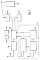
- FIG. 1 shows a receiving device in a vehicle that is a participant in a fleet
- FIG. 2 shows the control and disposition of the fleet via a trunked radio network and a long-wave transmitter
- FIG. 3 time slots for the transmission of additional data
- FIG. 4 an RDS channel in the VHF frequency band.
- 1 denotes a receiving device.
- the receiving device 1 contains a receiver 70 for GPS location data, which are fed to the receiver 70 via a first receiving antenna 71.
- the receiving device 1 also contains a second receiving antenna 6, which is connected to an evaluation unit 55 via a receiver 5 for DGPS correction location data.
- the DGPS correction location data evaluated by the evaluation unit 55 are fed to the receiver 70 for GPS location data.
- the evaluation unit 55 and the receiver 70 for GPS location data are connected to an on-board computer 60.
- a display device 20, a keyboard 25, a transceiver 65, a transponder 35 and a control device 40 are connected to the on-board computer 60.
- the transceiver 65 is provided with a transceiver antenna 66. Information from the on-board computer 60 can be fed to a radio device 30 which is matched to the transmission frequency of the transponder 35.
- Additional data on long wave are received in receiver 5 for DGPS correction location data and forwarded to evaluation unit 55.
- the received long-wave signal is time-divisionally divided into four time slots 80, 81, 82 and 83 according to FIG. 3.
- One of the four time slots 80, 81, 82 and 83, for example the first time slot 80, is reserved for the transmission of the DGPS correction location data.
- the remaining three time slots 81, 82 and 83 can be used for further additional data.
- the three remaining time slots 81, 82 and 83 are permanently assigned to the additional additional data or as required, that is to say that the additional services provided with the additional additional data are each associated with a corresponding time slot of the remaining three time slots 81, 82 and 83 coupled.
- the peculiarity of the use of long-wave signals for the transmission of the DGPS correction location data and the additional data is the constant (24 hours a day) availability and the large spatial range (greater than 500 km radius). In this way, unlimited and nationwide coverage or accessibility within the reception area can be achieved with a single omnidirectional transmitter. Geographical expansions that exceed the coverage performance by a single transmitter can be realized with several radio cells. On the other hand, due to the low signal bandwidth of the transmitter, undisturbed reception is possible even under very unfavorable reception conditions.
- the reception interference immunity and data integrity of the DGPS correction location data and the radio telegrams containing further additional data are ensured by using sufficiently known error-correcting block methods.
- the evaluation unit 55 has the task of selecting the incoming time slots 80, 81, 82 and 83. In this case, the DGPS correction location data present in the RTCM format in the first time slot 80 are selected and forwarded to the receiver 70 for GPS location data. The evaluation unit 55 also has the task of selecting from the remaining three remaining time slots 81, 82 and 83 the desired additional data or those required by the on-board computer 60 and forwarding them to the on-board computer 60.
- the GPS location data receiver 70 receives GPS signals emitted from satellites. In the receiver 70 for GPS location data, the corresponding satellite useful signals are evaluated to determine one's own location on the earth's surface. Other system solutions use on-board sensors for dead reckoning, but usually still have a GPS receiver as fallback level.
- the GPS location accuracy is hardly better than 100 m on average, this inaccuracy is reduced with the help of the DGPS correction location data to such an extent that the average location error is less than 5 m.
- the DGPS correction location data are acquired by means of suitable methods at a reference location and, as already described, are emitted via the first time slot 80 of a long-wave signal. With the aid of the DGPS correction location data supplied to the receiver 70 for GPS location data, the corrected position in the receiver 70 for GPS location data is then output in real time to the on-board computer 60 for storage.
- the on-board computer 60 has the task of forwarding the corrected location data to the transceiver 65 so that they can be transmitted to a control center via the transceiver antenna 66. Furthermore, the on-board computer 60 serves to evaluate the selected additional data supplied to it by the evaluation unit 55 and, if necessary, to display them via the display device 20.
- FIG. 2 shows the use of the arrangement according to FIG. 1 in a motor vehicle which is a participant in a fleet which is dispatched and controlled by a control center 90 via trunked radio in a range 10 according to FIG.
- 45 furthermore characterizes a first motor vehicle located in the spreading area 10 and 50 a second motor vehicle located outside the spreading area 10.
- Both motor vehicles 45 and 50 are equipped with a device according to FIG. 1.
- the two receiving antennas 71 and 6 are combined to form a common multi-band antenna 110.
- Measurement signals for the satellite-based positioning system GPS are transmitted via three satellites 75, 76 and 77 located in an orbit 78.
- a GPS reference receiver 85 is connected via a control center 90 to a long-wave transmitter 15, which transmits 16 DGPS correction location data via an omnidirectional antenna emits.
- the control center 90 is also connected via a trunked radio transceiver 115 to a first antenna 17 for trunked radio, which is located in the propagation area 10.
- the first antenna 17 for trunked radio together with a second and a third antenna 18 and 19 for trunked radio, provides the propagation area 10 with signals from the control center 90 second antenna 17 and 18 for trunked radio a data exchange with the control center 90 through.
- the multiband antennas 110 of the first and second motor vehicles 45 and 50 are supplied with measurement signals from the three satellites 75, 76 and 77, just like the GPS reference receiver 85 via its antenna 86.
- the range of the long-wave transmitter 15 with the omnidirectional antenna 16 is shown in FIG Concentric circles are shown, the center of which is the omnidirectional antenna 16. Both the first motor vehicle 45 in the range 10 and the second motor vehicle 50 outside the range 10 are within the range of the long-wave transmitter 15. The entire range 10 is within the range of the long-wave transmitter 15.
- the GPS reference receiver 85 receives GPS signals from the satellites 75, 76 and 77.
- the receiver-internal software calculates DGPS correction location data from the received measurement signals, which data are output to the control center 90 in RTCM format.
- the DGPS correction location data are stored in a computer in the control center 90 and are forwarded in real time to the long-wave transmitter 15.
- the DGPS correction location data is modulated in the long-wave transmitter 15 of a carrier wave and emitted via the omnidirectional antenna 16 in the first time slot 80 of the long-wave signal generated.
- the two motor vehicles 45 and 50 are participants in a fleet that is dispatched and controlled by the control center 90.
- the Control center 90 via the trunked radio transceiver 115 and the antennas 17, 18 and 19 for trunked radio control signals which can be received in the propagation area 10.
- the control information received in the corresponding motor vehicle via the transceiver antenna 66 is evaluated in the on-board computer 60 and displayed in the display device 20.
- the positions of the corresponding motor vehicle determined in the receiving device 1 are fed to the transceiver 65 via the on-board computer 60 and are emitted by the transceiver antenna 66.
- the radiated position data are fed to the trunked radio transceiver 115 via the antennas 17, 18 and 19 for trunked radio and from there to the control center 90 for evaluation.
- the control center 90 is informed of where the corresponding motor vehicles are located, so that they can be appropriately dispatched from there.
- the control information received in the corresponding motor vehicle is confirmed by corresponding keyboard input using the keyboard 25, which is forwarded via the on-board computer 60 to the transceiver 65 for transmission via the transceiver antenna 66.
- the first motor vehicle 45 in the expansion area 10 can be controlled by the control center 90.
- a participant of the fleet is outside the range 10, like the second motor vehicle 50, he can no longer be reached from the control center 90 via trunked radio.
- the second motor vehicle 50 can therefore only be reached via the long-wave transmitter 15, since it is within the range of this transmitter.
- the control center 90 no longer receives position data from the second vehicle 50, then it assumes that the second motor vehicle 50 has left the expansion area 10.
- the control center 90 is then one of the three remaining time slots 81, 82 and 83 of the long-wave signal generated in the long-wave transmitter 15 additional data, such as an encoded call that only that to address addressed second motor vehicle 50.
- This message is received by the multi-band antenna 110, selected in the evaluation unit 55, evaluated in the on-board computer 66 and displayed in the display device 20.
- the message contains, for example, a confirmation request telegram, which causes the fleet participants to either return to the area 10 or to contact the control center 90 by another route, such as a telephone or radio telephone. If there is no response from the fleet participant after a predetermined time, a signal is emitted via the transponder 35, which can be received by the radio 30 within the range of the transponder 35, so that a vehicle driver who has left the vehicle and is within the range of the Transponders 35 is located, can be reached. In this way, it is of course also possible to reach a vehicle driver who has left his vehicle within the range 10. However, the transponder 35 has a comparatively short range.
- a radio-controlled theft or immobilizer can also be implemented within the range of the long-wave transmitter 15.
- the corresponding additional data which are selected in the evaluation unit 55 and evaluated by the on-board computer 60, enter the control unit 40 and lead there to switching operations which activate or deactivate the immobilizer. If a vehicle driver leaves his motor vehicle, he notifies the control center 90, which then has additional data sent to activate the immobilizer. If the driver wants to use his motor vehicle again, he also informs the control center 90, which then sends out additional data for deactivating the immobilizer.
- control center 90 can also send out additional data in the remaining three time slots 81, 82 and 83, which contain a wake-up telegram which, after selection in the evaluation unit 55 and evaluation in the on-board computer 60 Representation of a switch-on request to switch on the transceiver 65 for communication with the control center 90 on the display device.
- the control center can have additional data sent out via the remaining three time slots 81, 82 and 83, which contain a sleep telegram, which, after selection in the evaluation unit 55 and evaluation in the on-board computer 60 Representation of a switch-off request to switch off the transceiver 65 or to switch on a power saving mode on the display device 20.
- the transponder 35 is only required if the radio 30 does not operate in the same frequency band as the transceiver 65, since a frequency conversion is then required. When using the same frequency band, no transponder 35 is required and it is sufficient to keep a channel free in this frequency band on which the radio 30 can be addressed.
- an ultra-short wave transmitter is used instead of the long wave transmitter 15.
- the receiver 5 for DGPS correction location data must also be an ultra-short wave receiver.
- 95 denotes an FM frequency band in which an audio signal and an RDS channel are transmitted.
- 4 101 identifies the spectrum of the audio signal in the lower part of the FM frequency band 95 and separately therefrom in the upper part of the FM frequency band is the lower sideband 105 and the upper sideband 106 of the RDS channel, which is modulated onto a subcarrier 100 located at the frequency f H in the middle between the two sidebands 105 and 106.
- the RDS channel 105, 106 is specially set up for additional data. Like the long-wave signal according to FIG. 3, the RDS channel 105, 106 can be divided into time slots 80, 81, 82 and 83 for the transmission of the DGPS correction location data and further additional data. The use of a dedicated RDS channel is also conceivable for long waves.
Abstract
Description
Die Erfindung geht von einer Empfangseinrichtung zur Auswertung von Ortungsdaten nach der Gattung des Hauptanspruchs aus.The invention is based on a receiving device for evaluating location data according to the type of the main claim.
Aus der Druckschrift "DGON-Seminar SATNAV 94, Satellitennavigationssysteme, Grundlagen und Anwendungen", 24. bis 26. Oktober 1994, Hamburg sind Untersuchungen zur bundesweiten Ausstrahlung von DGPS-Korrekturortungsdaten für Echtzeitanwendungen bekannt. Die Druckschrift zeigt den prinzipellen Aufbau von Referenz- und Mobilstation. Eine Referenzstation weist einen GPS-Empfänger auf, der über einen Personal-Computer mit dem Sende-Modem eines Telekom-Langwellensenders verbunden ist. Aus den empfangenen GPS-Ortungsdaten werden durch die empfängerinterne Software DGPS-Korrekturortungsdaten berechnet und im RTCM-Format (RTCM = Radio Technical Commission For Maritme Services) ausgegeben. Im Sende-Modem werden die DGPS-Korrekturortungsdaten einer Trägewelle aufmoduliert und vom Langwellensender ausgestrahlt. Die ausgestrahlten DGPS-Korrekturortungsdaten werden von mobilen Stationen mit Festfrequenzlangwellenempfängern empfangen. Die mobilen Stationen weisen einen Personal-Computer und einen GPS-Empfänger auf, denen die vom Festfrequenzlangwellenempfänger empfangenen DGPS-Korrekturortungsdaten zugeführt werden, wobei der GPS-Empfänger zusätzlich mit dem Personal-Computer verbunden ist. Die empfangenen Korrekturdatensätze im RTCM - Format werden im Personal-Computer der mobilen Station gespeichert und anschließend zur Berechnung der verbesserten Position der mobilen Antenne an den GPS-Empfänger weitergegeben. Durch empfängerinterne Software wird für jeden ankommenden Korrekturdatensatz eine aktuelle Position ermittelt. Das entstandene Positionsfile wird vom GPS-Empfänger dem Personal-Computer zugeführt und dort gespeichert.From the publication "DGON-Seminar SATNAV 94, satellite navigation systems, basics and applications", October 24 to 26, 1994, Hamburg, studies on the nationwide broadcast of DGPS correction location data for real-time applications are known. The publication shows the basic structure of the reference and mobile station. A reference station has a GPS receiver, which is connected via a personal computer to the transmission modem of a telecom long-wave transmitter. DGPS correction location data is calculated from the received GPS location data by the receiver's internal software and output in RTCM format (RTCM = Radio Technical Commission For Maritime Services). The DGPS correction location data of a carrier wave are modulated in the send modem and broadcast by the long-wave transmitter. The DGPS correction location data broadcast are used by mobile stations Fixed frequency longwave receivers received. The mobile stations have a personal computer and a GPS receiver, to which the DGPS correction location data received by the fixed-frequency long-wave receiver are fed, the GPS receiver being additionally connected to the personal computer. The received correction data records in RTCM format are stored in the personal computer of the mobile station and then passed on to the GPS receiver for calculating the improved position of the mobile antenna. A current position is determined for each incoming correction data record by receiver-internal software. The resulting position file is fed from the GPS receiver to the personal computer and saved there.
Die erfindungsgemäße Empfangseinrichtung mit den Merkmalen des Hauptanspruchs hat demgegenüber den Vorteil, daß eine kostensparende und wenig aufwendige Möglichkeit zum Empfang und zur Auswertung von Zusatzdaten neben den Korrekturortungsdaten mit ein und demselben Empfänger gegeben ist.The receiving device according to the invention with the features of the main claim has the advantage that there is a cost-saving and inexpensive way to receive and evaluate additional data in addition to the correction location data with one and the same receiver.
Durch die in den Unteransprüchen aufgeführten Maßnahmen sind vorteilhafte Weiterbildungen und Verbesserungen der im Hauptanspruch angegebenen Empfangseinrichtung möglich.Advantageous further developments and improvements of the receiving device specified in the main claim are possible through the measures listed in the subclaims.
Vorteilhaft gemäß den Ansprüchen 4 und 5 ist die Ausnutzung freistehender Datenzeitschlitze für die weiteren Zusatzdaten. Auf diese Weise sind mehr Informationen übertragbar.Advantageous according to
Vorteilhaft nach Anspruch 5 ist die Reservierung eines eigenen Kanals für die Zusatzdaten. Auf diese Weise ist ein verbesserter Zugriff mit größerer Störsicherheit auf die Zusatzdaten möglich. Vorteilhaft nach Anspruch 6 und Anspruch 8 ist die Möglichkeit für eine Leitstelle, einen Benutzer der Empfangseinrichtung zu erreichen, auch wenn der Sendeempfänger zur Kommunikation mit der Leitstelle abgeschaltet ist oder sich außerhalb der Reichweite des von der Leitstelle üblicherweise verwendeten Funknetzes befindet.Advantageous according to
Vorteilhaft nach Anspruch 7 ist die Möglichkeit für die Leitstelle, den Benutzer eines eingeschalteten Sendeempfängers zum Ausschalten für den Fall zu bewegen, daß keine Kommunikation mit der Leitstelle vorgesehen oder möglich ist.Advantageous according to claim 7 is the possibility for the control center to persuade the user of a switched-on transceiver to switch off in the event that no communication with the control center is provided or possible.
Vorteilhaft nach Anspruch 9 ist die Möglichkeit, einen Benutzer, der sich nicht bei der Bmpfangseinrichtung aufhält, zu erreichen.An advantage of claim 9 is the ability to reach a user who is not at the reception device.
Vorteilhaft nach Anspruch 10 ist die hohe Zuverlässigkeit einer funkgesteuerten Diebstahlsperre.The advantage of
Als Vorteil nach Anspruch 12 ist anzusehen, daß Teilnehmer eine Flotte auch dann Informationen zur Flottensteuerung erhalten können, wenn sie über den üblichen Funkweg nicht mehr erreichbar sind.An advantage according to claim 12 is that participants can receive a fleet control information even if they can no longer be reached via the usual radio path.
Ein Ausführungsbeispiel der Erfindung ist in der Zeichnung dargestellt und in der nachfolgenden Beschreibung näher erläutert. Es zeigen Figur 1 eine Empfangseinrichtung in einem Fahrzeug, das Teilnehmer einer Flotte ist, Figur 2 die Steuerung und Disposition der Flotte über ein Bündelfunknetz und einen Langwellensender, Figur 3 Zeitschlitze zur Übertragung von Zusatzdaten und Figur 4 einen RDS-Kanal im UKW-Frequenzband.An embodiment of the invention is shown in the drawing and explained in more detail in the following description. FIG. 1 shows a receiving device in a vehicle that is a participant in a fleet, FIG. 2 shows the control and disposition of the fleet via a trunked radio network and a long-wave transmitter, FIG. 3 time slots for the transmission of additional data, and FIG. 4 an RDS channel in the VHF frequency band.
In Figur 1 kennzeichnet 1 eine Empfangseinrichtung. Die Empfangseinrichtung 1 enthält einen Empfänger 70 für GPS-Ortungsdaten, die dem Empfänger 70 über eine erste Empfangsantenne 71 zugeführt werden. Die Empfangseinrichtung 1 enthält außerdem eine zweite Empfangsantenne 6, die über einen Empfänger 5 für DGPS-Korrekturortungsdaten mit einer Auswerteeinheit 55 verbunden ist. Die von der Auswerteeinheit 55 ausgewerteten DGPS-Korrekturortungsdaten werden dem Empfänger 70 für GPS-Ortungsdaten zugeführt. Die Auswerteeinheit 55 und der Empfänger 70 für GPS-Ortungsdaten sind mit einem Bordrechner 60 verbunden. An den Bordrechner 60 sind eine Anzeigeinrichtung 20, eine Tastatur 25, ein Sendeempfänger 65, ein Transponder 35 und ein Steuergerät 40 angeschlossen. Der Sendeempfänger 65 ist mit einer Sendeempfangsantenne 66 versehen. Einem auf die Sendefrequenz des Transponders 35 abgestimmten Funkgerät 30 sind Informationen vom Bordrechner 60 zuführbar.In Figure 1, 1 denotes a receiving device. The receiving device 1 contains a
Im Empfänger 5 für DGPS-Korrekturortungsdaten werden Zusatzdaten auf Langwelle empfangen und an die Auswerteeinheit 55 weitergegeben. Das empfangene Langwellensignal ist dabei zeitmultiplex in vier Zeitschlitze 80, 81, 82 und 83 gemäß Figur 3 aufgeteilt. Einer der vier Zeitschlitze 80, 81, 82 und 83, beispielsweise der erste Zeitschlitz 80, ist für die Übertragung der DGPS-Korrekturortungsdaten reserviert. Die restlichen drei Zeitschlitze 81, 82 und 83 können für weitere Zusatzdaten mitbenutzt werden. Dabei sind die drei restlichen Zeitschlitze 81, 82 und 83 den weiteren Zusatzdaten permanent oder nach Bedarf fest zugeordnet, das heißt, die mit den weiteren Zusatzdaten erbrachten Zusatzdienste sind jeweils an einen entsprechenden Zeitschlitz der restlichen drei Zeitschlitze 81, 82 und 83 gekoppelt. Die Besonderheit der Verwendung von Langwellensignalen zur Übertragung der DGPS-Korrekturortungsdaten und der weiteren Zusatzdaten besteht in der durchgängigen (24 Stunden pro Tag) Verfügbarkeit und der großen räumlichen Reichweite (größer 500 km Radius). Auf diese Weise ist eine zeitlich unbegrenzte und landesweite Abdeckung beziehungsweise Erreichbarkeit innerhalb des Empfangsbereichs mit einem einzigen Rundstrahlsender realisierbar. Geographische Ausdehnungen, die die Abdeckungsleistung durch einen einzigen Sender übersteigen, sind mit mehreren Funkzellen zu realisieren. Zum anderen ist bedingt durch die geringe Signalbandbreite des Senders ein ungestörter Empfang auch unter sehr ungünstigen Empfangsbedingungen möglich. Die Empfangsstörsicherheit und Datenintegrität der DGPS-Korrekturortungsdaten und die weiteren Zusatzdaten enthaltenden Funktelegramme wird durch den Einsatz hinreichend bekannter fehlerkorrigierender Blockverfahren abgesichert. Die Auswerteeinheit 55 hat die Aufgabe, die ankommenden Zeitschlitze 80, 81, 82 und 83 zu selektieren. Dabei werden die im RTCM-Format im ersten Zeitschlitz 80 vorliegenden DGPS-Korrekturortungsdaten selektiert und an den Empfänger 70 für GPS-Ortungsdaten weitergeleitet. Die Auswerteinheit 55 hat weiterhin die Aufgabe, aus den verbleibenden drei restlichen Zeitschlitzen 81, 82 und 83 die gewünschten beziehungsweise vom Bordrechner 60 benötigten weiteren Zusatzdaten zu selektieren und an den Bordrechner 60 weiterzuleiten. Der Empfänger 70 für GPS-Ortungsdaten empfängt GPS-Signale, die von Satelliten abgestrahlt werden. Im Empfänger 70 für GPS-Ortungsdaten erfolgt eine Auswertung der entsprechenden Satellitennutzsignale zur Ermittlung des eigenen Standortes auf der Erdoberfläche. Andere Systemlösungen setzen bordeigene Sensoren zur Koppelnavigation ein, besitzen als Rückfallebene jedoch meist noch einen GPS-Empfänger. Da aufgrund diverser externer wie systeminterner Einflüsse wie Zeitbasisfehler, Ausbreitungseffekte, Verzerrungen, usw. die GPS-Ortungsgenauigkeit im Durchschnitt kaum besser als 100 m ist, wird diese Ungenauigkeit mit Hilfe der DGPS-Korrekturortungsdaten soweit reduziert, daß der mittlere Ortungsfehler kleiner als 5 m wird. Dazu werden die DGPS-Korrekturortungsdaten mittels geeigneter Verfahren an einem Bezugsstandort erfaßt und wie bereits beschrieben über den ersten Zeitschlitz 80 eines Langwellensignals abgestrahlt. Mit Hilfe der dem Empfänger 70 für GPS-Ortungsdaten zugeführten DGPS-Korrekturortungsdaten wird dann im Empfänger 70 für GPS-Ortungsdaten die korrigierte Position in Echtzeit an den Bordrechner 60 zur Speicherung ausgegeben. Der Bordrechner 60 hat die Aufgabe die korrigierten Ortungsdaten an den Sendeempfänger 65 weiterzugeben, so daß sie über die Sendeempfangsantenne 66 an eine Leitstelle übermittelt werden können. Weiterhin dient der Bordrechner 60 dazu, die ihm von der Auswerteeinheit 55 zugeführten selektierten weiteren Zusatzdaten auszuwerten und gegebenenfalls über die Anzeigeeinrichtung 20 zur Darstellung zu bringen.Additional data on long wave are received in
Figur 2 zeigt den Einsatz der Anordnung gemäß Figur 1 in einem Kraftfahrzeug, das Teilnehmer einer Flotte ist, die von einer Leitstelle 90 über Bündelfunk in einem Ausbreitungsgebiet 10 gemäß Figur 2 disponiert und gesteuert wird. In Figur 2 kennzeichnen weiterhin 45 ein im Ausbreitungsgebiet 10 befindliches erstes Kraftfahrzeug und 50 ein außerhalb des Ausbreitungsgebietes 10 befindliches zweites Kraftfahrzeug. Beide Kraftfahrzeuge 45 und 50 sind mit einer Einrichtung gemäß Figur 1 ausgestattet. Dabei sind die beiden Empfangsantennen 71 und 6 zu einer gemeinsamen Multibandantenne 110 zusammengefaßt. Über drei auf einer Umlaufbahn 78 befindliche Satelliten 75, 76 und 77 werden Meßsignale für das satellitengestützte Ortungssstem GPS ausgestrahlt. Ein GPS-Referenzempfänger 85 ist über eine Leitstelle 90 mit einem Langwellensender 15 verbunden, der über eine Rundstrahlantenne 16 DGPS-Korrekturortungsdaten abstrahlt. Die Leitstelle 90 ist außerdem über einen Bündelfunksendeempfänger 115 mit einer ersten Antenne 17 für Bündelfunk, die sich im Ausbreitungsgebiet 10 befindet, verbunden. Die erste Antenne 17 für Bündelfunk versorgt zusammen mit einer zweiten und einer dritten Antenne 18 und 19 für Bündelfunk das Ausbreitungsgebiet 10 mit Signalen von der Leitstelle 90. Die Sendeempfangsantenne 66 des ersten Kraftfahrzeugs 45 im Ausbreitungsgebiet 10 führt über den Bündelfunksendeempfänger 115, die erste und die zweite Antenne 17 und 18 für Bündelfunk einen Datenaustausch mit der Leitstelle 90 durch. Den Multibandantennen 110 des ersten und des zweiten Kraftfahrzeuges 45 und 50 sind Meßsignale der drei Satelliten 75, 76 und 77 zugeführt, genauso wie dem GPS-Referenzempfänger 85 über dessen Antenne 86. Die Reichweite des Langwellensenders 15 mit der Rundstrahlantenne 16 ist in Figur 2 durch konzentrische Kreise dargestellt, deren Zentrum die Rundstrahlantenne 16 ist. Sowohl das erste Kraftfahrzeug 45 im Ausbreitungsgebiet 10 als auch das zweite Kraftfahrzeug 50 außerhalb des Ausbreitungsgebietes 10 befinden sich innerhalb der Reichweite des Langwellensenders 15. Das gesamte Ausbreitungsgebiet 10 befindet sich in der Reichweite des Langwellensenders 15.
Der GPS-Referenzempfänger 85 empfängt GPS-Signale von den Satelliten 75, 76 und 77. Aus den empfangenen Meßsignalen berechnet die empfängerinterne Software DGPS-Korrekturortungsdaten, die im RTCM-Format an die Leitstelle 90 ausgegeben werden. In einem Rechner der Leitstelle 90 werden die DGPS-Korrekturortungsdaten gespeichert und in Echtzeit an den Langwellensender 15 weitergeleitet. Die DGPS-Korrrekturortungsdaten werden im Langwellensender 15 einer Trägerwelle aufmoduliert und über die Rundstrahlantenne 16 im ersten Zeitschlitz 80 des erzeugten Langwellensignals abgestrahlt. Die beiden Kraftfahrzeuge 45 und 50 sind Teilnehmer einer Flotte, die von der Leitstelle 90 disponiert und gesteuert wird. Zu diesem Zweck sendet die Leitstelle 90 über den Bündelfunksendeempfänger 115 und die Antennen 17, 18 und 19 für Bündelfunk Steuersignale aus, die im Ausbreitungsgebiet 10 empfangbar sind. Die über die Sendeempfangsantenne 66 im entsprechenden Kraftfahrzeug empfangenen Steuerinformationen werden im Bordrechner 60 ausgewertet und in der Anzeigeeinrichtung 20 zur Darstellung gebracht. Die in der Empfangseinrichtung 1 ermittelten Positionen des entsprechenden Kraftfahrzeugs werden über den Bordrechner 60 dem Sendeempfänger 65 zugeführt und von der Sendeempfangsantenne 66 abgestrahlt. Über die Antennen 17, 18 und 19 für Bündelfunk werden die abgestrahlten Positionsdaten dem Bündelfunksendeempfänger 115 zugeführt und von dort an die Leitstelle 90 zur Auswertung weitergegeben. Auf diese Weise wird der Leitstelle 90 mitgeteilt, wo sich die entsprechenden Kraftfahrzeuge befinden, so daß sie von dort aus entsprechend disponiert werden können. Die Bestätigung empfangener Steuerinformationen im entsprechenden Kraftfahrzeug erfolgt durch entsprechende Tastatureingabe mittels der Tastatur 25, die über den Bordrechner 60 an den Sendeempfänger 65 zur Abstrahlung über die Sendeempfangsantenne 66 weitergeleitet wird. Auf diese Weise läßt sich das erste Kraftfahrzeug 45 im Ausbreitungsgebiet 10 von der Leitstelle 90 steuern. Befindet sich jedoch ein Teilnehmer der Flotte außerhalb des Ausbreitungsgebietes 10, wie das zweite Kraftfahrzeug 50, so läßt er sich nicht mehr über Bündelfunk von der Leitstelle 90 erreichen. Das zweite Kraftfahrzeug 50 läßt sich daher nur noch über den Langwellensender 15 erreichen, da es sich innerhalb der Reichweite dieses Senders befindet. Empfängt also die Leitstelle 90 keine Positionsdaten mehr vom zweiten Kraffahrzeug 50, dann geht sie davon aus, daß das zweite Kraftfahrzeug 50 das Ausbreitungsgebiet 10 verlassen hat. Die Leitstelle 90 wird dann über einen der drei verbleibenden Zeitschlitze 81, 82 und 83 des im Langwellensender 15 erzeugten Langwellensignals Zusatzdaten, wie beispielswiese einen codierten Ruf, der nur das gezielt adressierte zweite Kraftfahrzeug 50 erreichen soll, aussenden. Diese Nachricht wird von der Multibandantenne 110 empfangen, in der Auswerteeinheit 55 selektiert, im Bordrechner 66 ausgewertet und in der Anzeigeeinrichtung 20 zur Darstellung gebracht. Die Nachricht enthält dabei beispielsweise ein Rückmeldeaufforderungstelegramm, das den Flottenteilnehmer veranlaßt, entweder wieder in das Ausbreitungsgebiet 10 zu gelangen oder über einen anderen Weg, wie zum Beispiel Telefon oder Funktelefon Kontakt mit der Leitstelle 90 aufzunehmen. Erfolgt nach einer vorgegebenen Zeit keine Reaktion des Flottenteilnehmers, so wird über den Transponder 35 ein Signal abgestrahlt, das vom Funkgerät 30 innerhalb der Reichweite des Transponders 35 empfangbar ist, so daß auch ein Fahrzeugführer, der das Fahrzeug verlassen hat und sich innerhalb der Reichweite des Transponders 35 befindet, erreichbar ist. Auf diese Weise läßt sich natürlich auch ein Fahrzeugführer, der sein Fahrzeug innerhalb des Ausbreitungsgebietes 10 verlassen hat, erreichen. Der Transponder 35 hat jedoch eine vergleichsweise geringe Reichweite.FIG. 2 shows the use of the arrangement according to FIG. 1 in a motor vehicle which is a participant in a fleet which is dispatched and controlled by a
The
Durch Ausnutzung der drei verbleibenden Zeitschlitze 81, 82 und 83 läßt sich auch eine funkgesteuerte Diebstahlbeziehungsweise Wegfahrsperre innerhalb der Reichweite des Langwellensenders 15 realisieren. Die entsprechenden Zusatzdaten, die in der Auswerteeinheit 55 selektiert und vom Bordrechner 60 ausgewertet werden, laufen im Steuergerät 40 ein und führen dort zu Schaltvorgängen, die die Wegfahrsperre aktivieren beziehungsweise deaktivieren. Verläßt ein Fahrzeugführer sein Kraftfahrzeug, so teilt er dies der Leitstelle 90 mit, die daraufhin Zusatzdaten zur Aktivierung der Wegfahrsperre aussenden läßt. Möchte der Fahrzeugführer sein Kraftfahrzeug wieder benutzen, so teilt er dies ebenfalls der Leitstelle 90 mit, die daraufhin Zusatzdaten zur Deaktivierung der Wegfahrsperre aussenden läßt.By using the three remaining
Für die Kraftfahrzeuge 45 und 50 innerhalb der Reichweite des Langwellensenders 15 lassen sich von der Leitstelle 90 in den verbleibenden drei Zeitschlitzen 81, 82 und 83 außerdem Zusatzdaten aussenden, die ein Aufwecktelegramm enthalten, das nach Selektion in der Auswerteeinheit 55 und Auswertung im Bordrechner 60 die Darstellung einer Einschaltaufforderung zum Einschalten des Sendeempfängers 65 zur Kommunikation mit der Leitstelle 90 auf der Anzeigeeinrichtung zur Folge hat.For the
Soll die Flottensteuerung beendet werden oder ist sie aus anderen Gründen nicht möglich, dann kann die Leitstelle über die verbleibenden drei Zeitschlitze 81, 82 und 83 Zusatzdaten aussenden lassen, die ein Einschlaftelegramm enthalten, das nach Selektion in der Auswerteeinheit 55 und Auswertung im Bordrechner 60 die Darstellung einer Ausschaltforderung zum Ausschalten des Sendeempfängers 65 oder zum Einschalten eines Stromsparmodus auf der Anzeigeeinrichtung 20 zur Folge hat. Der Transponder 35 ist nur dann erforderlich, wenn das Funkgerät 30 nicht im gleichen Frequenzband wie der Sendeempfänger 65 arbeitet, da dann eine Frequenzumsetzung erforderlich ist. Bei Verwendung des gleichen Frequenzbandes ist kein Transponder 35 erforderlich und es genügt, in diesem Frequenzband einen Kanal freizuhalten, auf dem das Funkgerät 30 angesprochen werden kann.If the fleet control is to be ended or if it is not possible for other reasons, the control center can have additional data sent out via the remaining three
In einer weiteren Ausführungsform gemäß Figur 4 wird anstelle des Langwellensenders 15 ein Ultrakurzwellensender verwendet. Dann muß auch der Empfänger 5 für DGPS-Korrekturortungsdaten ein Ultrakurzwellenempfänger sein. In Figur 4 kennzeichnet 95 ein UKW-Frequenzband, in dem ein Audiosignal und ein RDS-Kanal übertragen werden. Dabei kennzeichnet in Figur 4 101 das Spektrum des Ausdiosignals im unteren Teil des UKW-Frequenzbandes 95 und getrennt davon im oberen Teil des UKW-Frequenzbandes befindet sich das untere Seitenband 105 und das obere Seitenband 106 des RDS-Kanals, der auf einen in der Mitte zwischen den beiden Seitenbändern 105 und 106 befindlichen Hilfsträger 100 bei der Frequenz fH aufmoduliert ist.In a further embodiment according to FIG. 4, an ultra-short wave transmitter is used instead of the
Der RDS-Kanal 105, 106 ist eigens für Zusatzdaten eingerichtet. Der RDS-Kanal 105, 106 läßt sich wie das Langwellensignal gemäß Figur 3 in Zeitschlitze 80, 81, 82 und 83 zur Übertragung der DGPS-Korrekturortungsdaten und weiterer Zusatzdaten einteilen. Die Verwendung eines eigenen RDS-Kanals ist auch bei Langwelle denkbar.The
Claims (12)
Applications Claiming Priority (2)
| Application Number | Priority Date | Filing Date | Title |
|---|---|---|---|
| DE19538694 | 1995-10-18 | ||
| DE19538694A DE19538694A1 (en) | 1995-10-19 | 1995-10-19 | Receiving device for evaluating location data |
Publications (2)
| Publication Number | Publication Date |
|---|---|
| EP0769704A2 true EP0769704A2 (en) | 1997-04-23 |
| EP0769704A3 EP0769704A3 (en) | 1998-11-25 |
Family
ID=7775106
Family Applications (1)
| Application Number | Title | Priority Date | Filing Date |
|---|---|---|---|
| EP96116131A Ceased EP0769704A3 (en) | 1995-10-18 | 1996-10-09 | Receiving device for the evaluation of location data |
Country Status (2)
| Country | Link |
|---|---|
| EP (1) | EP0769704A3 (en) |
| DE (1) | DE19538694A1 (en) |
Cited By (3)
| Publication number | Priority date | Publication date | Assignee | Title |
|---|---|---|---|---|
| EP0982601A1 (en) * | 1998-08-14 | 2000-03-01 | Robert Bosch Gmbh | Method and data receiver for receiving radio signals with correction data for a GPS |
| CN1087243C (en) * | 1997-10-07 | 2002-07-10 | 财团法人工业技术研究院 | Automotive anti-theft devide applying FM sub-carrier and difference correcting satellite positioning tech. |
| EP0926020A3 (en) * | 1997-12-22 | 2002-09-18 | Delphi Technologies, Inc. | Vehicle control using fm subcarrier messaging |
Families Citing this family (9)
| Publication number | Priority date | Publication date | Assignee | Title |
|---|---|---|---|---|
| DE19725669C1 (en) | 1997-06-18 | 1998-10-22 | Daimler Benz Ag | Vehicle stopping method for theft prevention |
| DE19733507A1 (en) * | 1997-08-04 | 1999-03-04 | Peter Rabels | Short-message service travel information method utilising mobile telephone |
| WO1999013673A1 (en) | 1997-09-09 | 1999-03-18 | Siemens Aktiengesellschaft | Method for protecting a limited local area against electromagnetic radiation emitted by mobile radiotelephone terminals, radio station and mobile radiotelephone terminal |
| DE19802595A1 (en) * | 1998-01-23 | 1999-07-29 | Volkswagen Ag | Motor vehicle with a navigation system |
| DE10038539A1 (en) * | 2000-08-03 | 2002-02-21 | Bosch Gmbh Robert | Method and device for energy-saving leak testing of a fuel tank system, in particular a motor vehicle |
| DE10119886A1 (en) * | 2001-04-24 | 2002-10-31 | Mueller Umwelttechnik | Position finding system for use in large towns, has Global Positioning System receiver for coarse position determination, and correction transmitters at distance for making measurement more accurate |
| DE10121260A1 (en) * | 2001-04-30 | 2002-11-21 | Siemens Ag | Navigation system as expansion for satellite navigation devices in indoor range, e.g. for determining the location of a vehicle has at least one portable receiver of position information signals that are not satellite signals |
| TWI269046B (en) * | 2004-06-29 | 2006-12-21 | Lite On Automotive Corp | A GPS having a vehicle condition real-time reporting function |
| TWI246973B (en) * | 2004-06-30 | 2006-01-11 | Sin Etke Technology Co Ltd | Vehicle anti-thief system by making the vehicle unable to operate normally |
Citations (6)
| Publication number | Priority date | Publication date | Assignee | Title |
|---|---|---|---|---|
| US4751512A (en) * | 1986-01-21 | 1988-06-14 | Oceanonics, Inc. | Differential navigation system for remote mobile users |
| US5003317A (en) * | 1989-07-11 | 1991-03-26 | Mets, Inc. | Stolen vehicle recovery system |
| DE4136136C1 (en) * | 1991-11-02 | 1993-03-04 | Westdeutscher Rundfunk, Anstalt Des Oeffentlichen Rechts, 5000 Koeln, De | |
| WO1994012892A1 (en) * | 1992-12-02 | 1994-06-09 | Voxson International Pty. Limited | Positioning systems utilizing mobile telephone system for correction signals |
| US5361212A (en) * | 1992-11-02 | 1994-11-01 | Honeywell Inc. | Differential GPS landing assistance system |
| US5422813A (en) * | 1992-12-17 | 1995-06-06 | Stanford Telecommunications, Inc. | No-outage GPS/commercial RF positioning system |
Family Cites Families (23)
| Publication number | Priority date | Publication date | Assignee | Title |
|---|---|---|---|---|
| GB1595146A (en) * | 1977-10-17 | 1981-08-05 | Gen Electric | Position surveillance using one active ranging satellite and time of arrival of a signal from an independent satellite |
| US4161730A (en) * | 1977-10-17 | 1979-07-17 | General Electric Company | Radio determination using satellites transmitting timing signals with correction by active range measurement |
| US4651156A (en) * | 1982-02-08 | 1987-03-17 | Mcgraw-Edison Co. | Integrated radio location and communication system |
| DE3805810A1 (en) * | 1988-02-24 | 1989-09-07 | Amend Volker | Communication system for vehicles |
| US4897642A (en) * | 1988-10-14 | 1990-01-30 | Secura Corporation | Vehicle status monitor and management system employing satellite communication |
| US5025253A (en) * | 1988-10-14 | 1991-06-18 | Secura Corporation | System and method for remotely monitoring the connect/disconnect status of a multiple part vehicle |
| JPH0827593B2 (en) * | 1989-10-24 | 1996-03-21 | マツダ株式会社 | Navigation device for mobile |
| JPH082029B2 (en) * | 1989-10-27 | 1996-01-10 | 日産自動車株式会社 | In-vehicle GPS receiver |
| JP3017772B2 (en) * | 1990-06-06 | 2000-03-13 | マツダ株式会社 | Vehicle navigation device |
| FR2670002B1 (en) * | 1990-11-30 | 1994-06-24 | Leroy Philippe | METHOD AND SYSTEM FOR DETERMINING THE POSITION OF MOBILES FROM A LOCATION STATION AND APPARATUS FOR IMPLEMENTING THE METHOD. |
| US5311194A (en) * | 1992-09-15 | 1994-05-10 | Navsys Corporation | GPS precision approach and landing system for aircraft |
| US5477228A (en) * | 1993-04-13 | 1995-12-19 | Differential Corrections Inc. | Differential global positioning system using radio data system |
| ATE323292T1 (en) * | 1993-06-21 | 2006-04-15 | Buren Elke Van | SYSTEM FOR OBTAINING HELP TO PERSONS OR PASSENGERS OF VEHICLES CARRYING A MOBILE PHONE |
| GB2279478A (en) * | 1993-06-26 | 1995-01-04 | Ian Paul Downing Hunter | Vehicle security |
| DE4322288A1 (en) * | 1993-07-05 | 1995-01-12 | Amazonen Werke Dreyer H | Method for evaluating traffic messages |
| DE4326237C1 (en) * | 1993-07-31 | 1994-12-15 | Gsp Sprachtechnologie Ges Fuer | Method for determining the location of vehicles in public passenger transport (public transport) |
| DE4340138A1 (en) * | 1993-11-25 | 1995-06-01 | Klaus Stanzl | Automatic vehicle location system using GPS, for recovery after theft |
| DE4403873A1 (en) * | 1994-02-08 | 1994-09-08 | Wenner Manfred E | Protection of movable objects against theft, and recovery of movable objects in the event of loss |
| DE4403990C2 (en) * | 1994-02-09 | 1996-09-05 | Panasonic Deutschland Gmbh | Theft protection method and for finding stolen mobile audio devices and motor vehicles and device for carrying out the method |
| DE4405385A1 (en) * | 1994-02-19 | 1995-09-07 | Bernd Dipl Ing Eslinger | Electronic equipment preventing unauthorised starting of vehicle |
| GB2287149B (en) * | 1994-03-02 | 1998-02-25 | Cossor Electronics Ltd | Differential global positioning system |
| DE9406605U1 (en) * | 1994-04-20 | 1994-09-22 | Vhb Funktechnik Gmbh | Stolen vehicle tracking system |
| DE4429121C1 (en) * | 1994-08-17 | 1996-02-22 | Siemens Ag | Navigation system for a vehicle |
-
1995
- 1995-10-19 DE DE19538694A patent/DE19538694A1/en not_active Withdrawn
-
1996
- 1996-10-09 EP EP96116131A patent/EP0769704A3/en not_active Ceased
Patent Citations (6)
| Publication number | Priority date | Publication date | Assignee | Title |
|---|---|---|---|---|
| US4751512A (en) * | 1986-01-21 | 1988-06-14 | Oceanonics, Inc. | Differential navigation system for remote mobile users |
| US5003317A (en) * | 1989-07-11 | 1991-03-26 | Mets, Inc. | Stolen vehicle recovery system |
| DE4136136C1 (en) * | 1991-11-02 | 1993-03-04 | Westdeutscher Rundfunk, Anstalt Des Oeffentlichen Rechts, 5000 Koeln, De | |
| US5361212A (en) * | 1992-11-02 | 1994-11-01 | Honeywell Inc. | Differential GPS landing assistance system |
| WO1994012892A1 (en) * | 1992-12-02 | 1994-06-09 | Voxson International Pty. Limited | Positioning systems utilizing mobile telephone system for correction signals |
| US5422813A (en) * | 1992-12-17 | 1995-06-06 | Stanford Telecommunications, Inc. | No-outage GPS/commercial RF positioning system |
Cited By (4)
| Publication number | Priority date | Publication date | Assignee | Title |
|---|---|---|---|---|
| CN1087243C (en) * | 1997-10-07 | 2002-07-10 | 财团法人工业技术研究院 | Automotive anti-theft devide applying FM sub-carrier and difference correcting satellite positioning tech. |
| EP0926020A3 (en) * | 1997-12-22 | 2002-09-18 | Delphi Technologies, Inc. | Vehicle control using fm subcarrier messaging |
| EP0982601A1 (en) * | 1998-08-14 | 2000-03-01 | Robert Bosch Gmbh | Method and data receiver for receiving radio signals with correction data for a GPS |
| US6332070B1 (en) | 1998-08-14 | 2001-12-18 | Robert Bosch Gmbh | Method and data receiver device for reception of a radio signal containing correction data for a global navigation satellite system |
Also Published As
| Publication number | Publication date |
|---|---|
| DE19538694A1 (en) | 1997-04-24 |
| EP0769704A3 (en) | 1998-11-25 |
Similar Documents
| Publication | Publication Date | Title |
|---|---|---|
| DE69636646T2 (en) | Two-way paging system and device | |
| DE69837034T2 (en) | SATELLITE BROADCASTING SYSTEM | |
| DE69836172T2 (en) | Location-dependent paging message processing | |
| DE4424412A1 (en) | Radio telecommunication system with satellite navigation for both mobile telephony and VHF radio reception | |
| EP0814345A2 (en) | Mobile object positioning system, especially for vehicles | |
| EP0769704A2 (en) | Receiving device for the evaluation of location data | |
| DE60028017T2 (en) | DEVICE AND METHOD FOR RADIO CALL IN A SATELLITE COMMUNICATION ARRANGEMENT WITH USER RANGE | |
| DE69331710T2 (en) | POSITIONING SYSTEM USING A MOBILE TELEPHONE FOR TRANSMITTING CORRECTION SIGNALS | |
| EP0679041A2 (en) | Emergency call system for mobile radio system | |
| DE4137000A1 (en) | Field strength dependent signal evaluating method for car radio - comparing obtained field strength profile with stored field strength profile held in memory to read out associated information | |
| EP0892379B1 (en) | Method and telematic equipment for gathering and broadcasting relevant traffic information | |
| EP0915577A2 (en) | System for using of mobil telephones in an traffic aircraft | |
| WO1993009446A1 (en) | System for determining the position of mobile objects | |
| DE60023310T2 (en) | PROCESS FOR INCREASING RADIO | |
| DE19836966A1 (en) | Method and data receiver for receiving radio signals containing correction data for a global navigation satellite system | |
| EP2728920B1 (en) | AIS marine transceiver detects a rogue base station | |
| DE60225394T2 (en) | Method and system for geographic location in communication networks and terminal therefor | |
| EP0932992B1 (en) | Method for radio signal transmission | |
| DE102005039807B4 (en) | Providing information in satellite navigation systems | |
| DE2815670C2 (en) | ||
| DE10011702A1 (en) | Information delivery method for road users involves receiving information by radio broadcast and determining the relevant location-related information using the mobile reception and data processing device | |
| DE102005007309A1 (en) | Mobile device for determining a current location using envirnment data and associated location information | |
| DE602004005069T2 (en) | PREVENTING PROBLEMS OF MOVABLE RADIATION NETWORKS | |
| DE102005015833B4 (en) | System for detecting the locations of satellite mobile phones | |
| DE60122217T2 (en) | Two-way sequencing system and methods using an existing network |
Legal Events
| Date | Code | Title | Description |
|---|---|---|---|
| PUAI | Public reference made under article 153(3) epc to a published international application that has entered the european phase |
Free format text: ORIGINAL CODE: 0009012 |
|
| AK | Designated contracting states |
Kind code of ref document: A2 Designated state(s): CH DE ES FR GB IT LI SE |
|
| PUAL | Search report despatched |
Free format text: ORIGINAL CODE: 0009013 |
|
| AK | Designated contracting states |
Kind code of ref document: A3 Designated state(s): CH DE ES FR GB IT LI SE |
|
| 17P | Request for examination filed |
Effective date: 19990525 |
|
| 17Q | First examination report despatched |
Effective date: 20020709 |
|
| STAA | Information on the status of an ep patent application or granted ep patent |
Free format text: STATUS: THE APPLICATION HAS BEEN REFUSED |
|
| 18R | Application refused |
Effective date: 20030404 |