EP0772056B1 - System for controlling the charge/discharge cycles of a rechargeable battery and host device including an intelligent battery - Google Patents
System for controlling the charge/discharge cycles of a rechargeable battery and host device including an intelligent battery Download PDFInfo
- Publication number
- EP0772056B1 EP0772056B1 EP96202928A EP96202928A EP0772056B1 EP 0772056 B1 EP0772056 B1 EP 0772056B1 EP 96202928 A EP96202928 A EP 96202928A EP 96202928 A EP96202928 A EP 96202928A EP 0772056 B1 EP0772056 B1 EP 0772056B1
- Authority
- EP
- European Patent Office
- Prior art keywords
- neural network
- discharge
- parameters
- battery
- instant
- Prior art date
- Legal status (The legal status is an assumption and is not a legal conclusion. Google has not performed a legal analysis and makes no representation as to the accuracy of the status listed.)
- Expired - Lifetime
Links
Images


Classifications
-
- G—PHYSICS
- G01—MEASURING; TESTING
- G01R—MEASURING ELECTRIC VARIABLES; MEASURING MAGNETIC VARIABLES
- G01R31/00—Arrangements for testing electric properties; Arrangements for locating electric faults; Arrangements for electrical testing characterised by what is being tested not provided for elsewhere
- G01R31/36—Arrangements for testing, measuring or monitoring the electrical condition of accumulators or electric batteries, e.g. capacity or state of charge [SoC]
- G01R31/367—Software therefor, e.g. for battery testing using modelling or look-up tables
-
- H—ELECTRICITY
- H02—GENERATION; CONVERSION OR DISTRIBUTION OF ELECTRIC POWER
- H02J—CIRCUIT ARRANGEMENTS OR SYSTEMS FOR SUPPLYING OR DISTRIBUTING ELECTRIC POWER; SYSTEMS FOR STORING ELECTRIC ENERGY
- H02J7/00—Circuit arrangements for charging or depolarising batteries or for supplying loads from batteries
- H02J7/007—Regulation of charging or discharging current or voltage
- H02J7/00712—Regulation of charging or discharging current or voltage the cycle being controlled or terminated in response to electric parameters
Definitions
- the invention relates to a control system for discharge-charge of a rechargeable battery, to form a smart battery.
- the invention also relates to a host device equipped with an intelligent battery.
- the invention finds its application in the field of modular devices equipped with a rechargeable battery such that for example: individual cell phones or professionals, cordless tools, computers laptops, toys ....
- smart battery we generally mean a rechargeable battery, coupled to a system that controls its amount of charge.
- This system includes means for collect data on the amount of charge the battery, and means for providing information calculated predictions regarding discharge conditions in the future.
- a technical problem posed by determination predictive information on discharge conditions in the future for a rechargeable battery is variability of battery construction parameters and the variability of the habits of the user of the device host.
- the variability of the construction parameters of the battery considered individually is due to dispersion structural data during manufacture, for the same Battery Type.
- a charge quantity control system for a battery, using a neural network is already known to the publication titled "Neural Network, A proper Approach to the Energy Management Problem ", by Marcus STOLL in” 10th European Photovoltaic Solar Energy conference ", 8-I 0 APRIL 1991, LISBON, PORTUGAL, p.427-430 ".
- the publication cited describes the use of a neural network to assume the task of estimating the amount of charge (SOC) of a battery lead-acid, in a recharging system (RES).
- RES recharging system
- determining the amount of charge (SOC) is an important task to be performed to control the energy level of a battery.
- the estimation of the amount of charge allows planning of the use of renewable energy, the optimization of conditions of use of an h & e device, taking decisions concerning the different phases of the cycles of discharge-charge of the battery.
- a neural network is trained, by means of a base of data, to estimate the amount of charge (SOC). To reduce cost, the neural network is trained on only one small part of the battery discharge range. As, during most of the time, the discharge current is very small, the training of the neural network is done in this area.
- this base of data may include information relating to the cycles of discharge and depth of discharge and at average temperature drums. Different batches of this data, forming input vectors, are supplied to the neural network for it learn the discharge behavior of the batteries.
- the network of neurons is organized for an appropriate representation of the battery behavior.
- a problem resulting from the use of the known system is that this system is not able to predict directly the time remaining before a critical voltage threshold discharge is reached.
- An object of the present invention is to provide a system for controlling the discharge-charge cycles of a battery which provides predictive information about when a predetermined critical discharge voltage threshold of the battery will be reached, and more particularly predictive information about the time remaining run from every current moment of use until this predetermined critical voltage threshold discharge will be reached.
- An object of the present invention is to provide a system for controlling the discharge-charge cycles of a battery which provides such predictive information that adapts automatically to new voltage data which varies at each phase of battery discharge depending on the number of discharge-charge cycles already carried out previously.
- An object of the present invention is to provide such control system that provides such information predictive that adapt to new real data from voltage which vary with each phase of battery discharge, compared to the predicted voltage data, due to the dispersion of the behavior of each individual battery by compared to average behavior.
- these problems are solved, as recited in Claim 4, by a control system as defined above, in which the first neural network carrying out the first calculation means, is arranged to calculate, during the charge phase which follows the discharge phase of the discharge-charge cycle concerned by a backpropagation method, real parameters which are its own real synaptic coefficients in the situation where, for each batch of instantaneous real values, the measurement of discharge voltage is imposed on its input, and the corresponding current instant is imposed on its output, the computer is arranged to supply the error parameters formed by the respective differences between said real synaptic coefficients calculated by the first neural network during said charging phase, and said approximate parameters calculated by the second network to neurons for said anterior discharge phase, the third neural network making the third calculation means, is arranged to calculate, by a backpropagation method, adaptive parameters which are its own adaptive synaptic coefficients, in the situation where the error parameters are imposed on its outputs and the initial values of the previous discharge phase are imposed on its inputs, this third neural network retaining, in the subsequent discharge
- control system in both of its embodiments is that the indications predictive adapt to the individual characteristics of discharge-charge of the battery to which this system control is coupled, either for a given type of battery, or for different types of batteries, because this control system has the advantage of being adaptive to any new cycle of charge-discharge.
- Another advantage is that these predictive indications are very precise and very reliable.
- a host device includes such a control system, this host device being powered by the rechargeable battery which is coupled to said system of control.
- the advantage of this system is that it is simple to set up artwork.
- the host device coupled to this system is particularly efficient.
- a control system 100 is coupled to a rechargeable battery 110, to constitute a global system called intelligent battery 120.
- This rechargeable battery has charging phases alternating with phases discharge according to consecutive discharge-charge cycles.
- the system 100 controls the discharge and possibly charge phases of the discharge-charge cycles of the rechargeable battery.
- This control system 100 includes a computer 160 to provide an indication of an instant t TH when, in a discharge phase, the battery 110 will reach a predetermined critical voltage threshold V TH and more specifically, to provide an indication of the lapse of time ⁇ T TH remaining to run, before this predetermined critical threshold of discharge voltage V TH is reached, or both indications.
- this intelligent battery 120 can be incorporated in, or coupled to this host device 130.
- this rechargeable battery 110 is coupled by connections D1, D2 to this host device 130.
- the host device further comprises display means 140, to provide the user with the time indications t TH or ⁇ TH , or both.
- the control system 100 is also coupled to means 150 measuring time, and battery voltage.
- a system 100 for controlling the discharge-charge cycles of a rechargeable battery 110 comprises first, second and third means of predictive and adaptive calculation coupled, denoted respectively NN1, NN2, and NN3, to provide , from the initial voltage values Vo, ⁇ Vo, No measured in a discharge phase, and from the fixed value of a critical voltage threshold V TH , the predictive indication of an instant called critical instant t TH where, in the same discharge phase, the battery voltage will reach this critical threshold V TH , and more specifically, a predictive indication of the time lapse ⁇ t TH remaining to run before this critical discharge voltage threshold V TH is reached , this threshold being predetermined so that, before the battery voltage reaches this threshold V TH , the battery 110 retains a precisely known operating energy, and located within a certain range where this energy is correctly adapted to the operation of a host device 130 which it supplies.
- the first, second and third means of calculation predictive and adaptive 100 control systems are respectively constituted by a first neural network referenced NN1, a second neural network referenced NN2 mounted in series with the first neural network NN1, and a third network of NN3 neurons mounted in parallel on the second network of neurons.
- a first discharge phase denoted PD1, starting at an instant to in a discharge-charge cycle, is first considered; and a predetermined critical discharge voltage threshold V TH is fixed.
- the coefficients synaptics or weights of this first NN1 neural network are at number of 13 and are referenced WjA where "j" is an index from 1 to 13. They are called the first WjA parameters and are calculated and supplied automatically during this first PD1 discharge phase, by the second network of NN2 neurons cooperating with the third network of NN3 neurons.
- This computer 160 further provides, in its function of adder, synaptic coefficients or weight WjA necessary for the functioning of the first neuron network during this first PD1 discharge phase, by adding the approximate WjB parameters from the second neural network and WjC correction parameters from the third network of neurons.
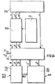
- control system further includes zones RAM 170b RAM to save or provide as appropriate, the variable measures and the weights of the first and third networks of neurons, and a ROM 170a read only memory area for storing data of structures of the neural networks NN1, NN2 and NN3, the fixed parameters and weights of the second NN2 neural network.
- Each of the neural networks NN1, NN2 and NN3 must be organized (or arranged) to carry out these calculations and provide these outputs. To this end, each of them is subject to a learning procedure and a test procedure called phases during which their synaptic coefficients are determined and, in some cases, fixed.
- the task of the first neural network NN1 is to learn models of discharge curves. This learning makes it possible to construct a relationship between the instantaneous value of the battery discharge voltage denoted Vt, and the current instant t when the battery reaches this voltage Vt.
- the NN1 neural network was built to generate a nonlinear function Fw.
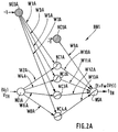
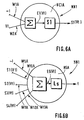
- each hidden neuron noted NC1A to NC4A, are those of a formal neuron "standard", and are illustrated in FIG.6A, which shows the cell hidden NC1A, for example.
- Each hidden neuron given NCiA receives on the one hand input the instantaneous voltage Vt with a weight, or coefficient input synaptic, which is one of the 13 weights referenced WjA, and receives on the other hand a threshold having for value the constant "-1", affected by another of the 13 weights referenced WjA.
- the index "i" is the index 1 to 4 of the hidden neural cell NC1A to NC4A concerned.
- Each hidden neuron NCiA achieves a weighted sum, denoted ⁇ , of the inputs assigned one of the weights WjA, and calculates an output intermediate Ei (Vt).
- the activation function Si is preferably a sigmoid function "tanh” equal to the hyperbolic tangent function, which is very well suited to the shape of the discharge curves to build, as will be shown later.
- the 4 neuronal cells NC1A to NC4A therefore show in the example described, a non-linear function "tanh”.
- the structure of the single NSA output neuron is illustrated in FIG. 6B. He realizes a weighted sum, noted ⁇ , of Si (Vt) outputs of all hidden NCiA neurons, using synaptic coefficients WjA, sum plus the value of a threshold "-1" coming from the hidden cell NCOA, this value of threshold being introduced into the NSA output neuron through one synaptic coefficients WjA.
- This output neuron therefore first performs the sum weighted ⁇ which gives an intermediate output Es (Vt).
- the Ls activation function of this output neuron is chosen linear.
- the output of the output neuron is the function Fw that we are trying to generate.
- weight ratings of each hidden NCiA neuron are shown in FIG. 2A, as well as the notations of the weights input from the NSA output neuron. All of these weights noted W1A to W13A is formed by the set of 13 weights WjA transmitted by the second and third neural networks NN2 and NN3 mounted in parallel whose outputs are coupled by the computer 160 to adder function.
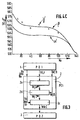
- a conventional curve discharge of a cadmium-nickel battery taken by way of example gives the instantaneous voltage Vt in volts as a function of time t in minutes.
- This curve shows a steep slope in the first battery run time, for example 100 first minutes, then a slight slope between 100 and 500 minutes of use, and finally again a steep slope beyond 500 minutes.
- this discharge curve is given quite done as an example.
- the first neural network NN1 must undergo training leading to supply a time t which is a function Fw of the battery voltage Vt.
- FIG.4B shows an example of a discharge curve which of interest in this description.
- This curve shows the time t as a function of the battery voltage Vt.
- This curve of FIG. 4B is drawn simply by carrying the values which were on the abscissa on FIG. 4A, on the ordinate on the FIG.4B; and by carrying the values which were on the ordinate on the FIG.4A on the abscissa in FIG.4B.
- this discharge curve has a shape approaching the shape of a curve "Tanh". This is why the functions of the type of sigmoid are preferred for performing activation functions in neurons of the hidden layer.
- FIG. 4B therefore provides a discharge curve giving the time t in minutes as a function of the voltage Vt in volts which shows almost flat end portions and an intermediate portion having a steep slope.
- the slopes of the activation functions If cells hidden NC1A, NC2A can be for example 7.0, and the slopes of activation functions of the following hidden cells NC2A, NC4A can be for example 2.0.
- discharge time t curves as a function of the voltage V (t) of discharge are recorded for example every minute for a large number N of discharge cycles, and for a large number of 110 batteries of the same type, for example batteries nickel-cadmium.
- 20 batteries are used, and undergo 140 discharge-charge cycles.
- 20 x 140 2800 discharge curves are recorded, so that each curve provides 1600 points.
- Each curve is taught to a different NN1 network. So in the learning phase, 2800 networks are initialized, that is to say 1 network per curve. In each curve, for example the half of the points, i.e. 800 points, is used to learning the corresponding neural network NN1 and, the other half of the points, i.e. 800 other points, is used to test said neural network NN1.
- the 13 WjA weights of each of the 2800 NN1 neural networks are stored in a RAM area RAM, referenced 170b in FIG.5B.
- the inputs constituted by the initial values Vo and ⁇ Vo were specifically chosen because that it appeared that these were the values most sensitive to battery characteristics.
- the third entry consisting of the initial number No of cycles, was also specifically chosen because it takes account of an aging effect of the battery, since the more a battery has undergone discharge-charge cycles, the less it it has life time left, that is to say the less the effect of the recharge is effective and the faster the discharge time.
- This aging effect is illustrated by FIG. 4C, which shows in ⁇ , measured points corresponding to the discharge time t TH to reach the critical threshold V TH from the initial instant to, as a function of the initial number of cycles No. These ⁇ measurements show that the greater the number of cycles already performed, the shorter the discharge time t TH .
- Synaptic coefficients or weights, referenced WnB of this second neural network are fixed during its phase and are stored in the ROM area ROM 170a, shown in FIG.5B.
- the output cells, noted NS1B to NS13B of the second neural network NN2 have a function non-linear activation, preferably "tanh”.
- this second neural network NN2 has hidden cells whose slope of the sigmoid activation function is different from cell to cell the other. This embodiment allows not to use a number important hidden cell.
- the second neural network NN2 is trained in using 1400 vectors of 13 weight values generated by learning the first neural network NN1 using the 2800 recorded curves, and the other 1400 generated vectors are used for testing.
- test procedure is carried out in the manner following: for the 1400 vectors which do not belong to the batch the corresponding initial values Vo, ⁇ Vo and No are applied to the inputs of the second neural network. This one computes an output vector of 13 weight values WjB as it has been trained to do so.
- This first neural network NN1 then calculates the automatically adapted predictive value of discharge time t TH which is compared with that of the test curve.
- the curve a giving the predictive indication of the time t TH of discharge as a function of the number of cycles No differs from a curve relying on the actual measurements ⁇ , that is to say that the control system makes an average error of approximately 10 min in the predictive determination of the instant t TH when the battery will reach the critical voltage threshold V TH .
- This error can be corrected by correcting the weights imposed for the functioning of the first neural network. This is done by not directly providing the first network with neurons NN1 the parameters WjB calculated by the second network of NN2 neurons, because they are approximate and cause error that we cited. This is therefore done by correcting these respectively approximate WjB parameters by WjC correction parameters, provided by the third neural network NN3, and in equal number to approximate WjB parameters.
- the approximate parameters WjB and the parameters correction WjC are added by the computer 160 in its adder function and the result is imposed on this first neural network NN1.
- the third neural network NN3 learns to calculate its own synaptic coefficients, or weights, as adaptive values, to enable it to calculate the correction parameters WjB which, added to the approximate parameters WjA supplied by the second neural network NN2, will constitute the synaptic coefficients or weights best suited to the functioning of the first neural network NN1.
- this first network of neurons NN1 provided with these adapted weights WjA will be able to provide, during the discharge, a predictive indication of the critical instant t TH closer to the real value.
- the difference between the predictive indication ⁇ of t TH and the measured value ⁇ is lowered to approximately 1 minute as demonstrated by the curves in FIG. 4C.
- This is a great advantage in obtaining the accuracy of predictive indications, since the control system goes from an error of 10 min over the 570 min duration of a discharge, to 1 min over these 570 min.
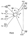
- the third neural network requires, for its operation, 4 input synaptic coefficients and 13 synaptic coefficients at output, i.e. a total of 17 coefficients synaptics noted WkC, where k is an index from 1 to 17.
- the adaptive synaptic coefficients WkC where k is a number from 1 to 17, corresponding to the structure of the third neural network, shown in FIG. 2C, which were calculated during the phase of load PC1 of the previous cycle, are kept for a new determination of the synaptic coefficients of the first network of NN1 neurons, as described above, in the procedure of operation of the control system.
- the third neural network NN3 provides in this new PD2 discharge phase, WjC correction parameters particularly well suited for correcting parameters approximate WjB provided by the second neural network NN2.
- the computer 160 performs this correction by performing the WjB + WjC addition which provides new coefficients synaptics better suited for the first neural network NN1 in this second discharge phase.
- the control system 100 has three operating modes called initialization mode, commonly used mode, and mode adaptive.
- the two values Vo and ⁇ Vo are supplied to the input of the second neural network NN2 which calculates then the vector of 13 weight values WjB to apply to the first neural network NN1A.
- the current usage mode is implemented during the discharge phase itself.
- the instantaneous voltage Vt is measured and stored every minute for the subsequent updating of the weights of the third neural network.
- the indications of time t TH or of time lapse ⁇ t TH are therefore provided every minute.
- the adaptive mode is implemented during the charging phase and includes the calculation of new synaptic weights Wkc for the third neural network NN3, from real instantaneous values Vt, t imposed on the first neural network NN1, from the calculation real parameters WjA * and the calculation of the error parameters WjC * reported on the third neural network NN3, according to the procedure described above with reference to FIG.1B and FIG.3.
- the control system 100 is implemented works by a microprocessor 160 to perform the calculations, and memory areas 170a, 170b for storing the data. These areas memory are accessible by microprocessor 160 and include a ROM storage memory area 170a for storing data from structure of neural networks NN1, NN2 and NN3, parameters and the WnB weights of the second neural network, and an area of RAM 170b RAM to save or provide as appropriate variable measures and the weight vectors WjA, WjC, WjA *, WjC * of the first and third neural networks.
- the microprocessor 160 performs the calculations necessary for the operation of the control.
- the control system 100 is coupled to display means 140 to provide the user with an indication of the time t TH or else of the time lapse ⁇ t TH remaining to run from a current instant t of use until the moment when the battery reaches this predetermined critical voltage threshold Vt TH , or both indications.
- control system 100 makes part of a host device 130 which comprises connection means D1, D2 for the 110 rechargeable battery.
- the rechargeable battery 110 is coupled to the control system 100 to form the battery intelligent 120.
- the host device 130 furthermore houses the means measurement 150, for example a multimeter, microprocessor 160, memory areas 170a, 170b accessible by microprocessor 160 and the display means 140.
- a device can be a screen with written indications, or with drawn indications, or a panel formed by diodes.
- a device can be a screen with written indications, or with drawn indications, or a panel formed by diodes.
Description
L'invention concerne un système de contrôle des cycles de décharge-charge d'une batterie rechargeable, pour former une batterie intelligente. L'invention concerne également un dispositif hôte équipe dune batterie intelligente.The invention relates to a control system for discharge-charge of a rechargeable battery, to form a smart battery. The invention also relates to a host device equipped with an intelligent battery.
L'invention trouve son application dans le domaine des appareils modulaires équipés dune batterie rechargeable tels que par exemple: les téléphones cellulaires individuels ou professionnels, les outils sans fil, les ordinateurs portables, les jouets....The invention finds its application in the field of modular devices equipped with a rechargeable battery such that for example: individual cell phones or professionals, cordless tools, computers laptops, toys ....
Par batterie intelligente, on entend généralement une batterie rechargeable, couplée à un système qui contrôle sa quantité de charge. Ce système comporte des moyens pour collecter des données sur la quantité de charge de la batterie, et des moyens pour fournir des informations prédictives calculées concernant les conditions de décharge dans le futur.By smart battery, we generally mean a rechargeable battery, coupled to a system that controls its amount of charge. This system includes means for collect data on the amount of charge the battery, and means for providing information calculated predictions regarding discharge conditions in the future.
Un problème technique posé par la détermination d'informations prédictives sur les conditions de décharge dans le futur, pour une batterie rechargeable, tient à la variabilité des paramètres de construction de la batterie et à la variabilité des habitudes de l'utilisateur du dispositif hôte.A technical problem posed by determination predictive information on discharge conditions in the future for a rechargeable battery is variability of battery construction parameters and the variability of the habits of the user of the device host.
La variabilité des paramètres de construction de la batterie considérée individuellement est due à la dispersion des données de structure en cours de fabrication, pour un même type de batterie.The variability of the construction parameters of the battery considered individually is due to dispersion structural data during manufacture, for the same Battery Type.
La variabilité des habitudes de l'utilisateur conduit à des abus qui peuvent endommager la batterie et affecter les possibilités ultérieures de recharge. Ces habitudes abusives comprennent des charges durant un laps de temps trop long, ou des recharges trop fréquentes d'une batterie non substantiellement déchargée.The variability of user habits leads to abuse that can damage the battery and affect subsequent recharging possibilities. These abusive habits include charges for too long, or too frequent recharges of a non-rechargeable battery substantially discharged.
Un autre problème technique tient aussi au fait que les applications actuelles des batteries rechargeables requièrent une très haute précision portant sur la quantité d'énergie disponible à un moment donné. Another technical problem is also that the current applications of rechargeable batteries require very high precision relating to the amount of energy available at some point.
Un appareil et une méthode pour prédire la décharge d'une
batterie sont déjà connus du brevet EP 0 420 530. Ce document
décrit une technique pour prédire la réserve de temps restant
avant qu'une batterie ne soit déchargée. Cette technique est
basée sur un algorithme d'état de charge adaptatif qui est
actif en temps réel pour répondre aux changements de
conditions de la batterie. Cet algorithme est basé sur des
caractéristiques de décharge mesurées de la batterie dont la
réserve de temps doit être prédite. Le nombre des
caractéristiques est réduit à deux paramètres déterminés à
partir d'une seule courbe avec une région linéaire et une
région exponentielle. Ces caractéristiques de décharge sont
combinées avec des paramètres dynamiques du système de
batterie contrôlés et calculés en temps réel afin de produire
une évaluation continuelle et une ré-évaluation de la réserve
de temps restant sous des conditions changeantes. Au cours de
la décharge, il y a une continuelle amélioration de la
prédiction de réserve de temps restant.An apparatus and method for predicting the discharge of a
battery are already known from
Un système de contrôle de la quantité de charge d'une batterie, utilisant un réseau de neurones est déjà connu de la publication intitulée "Neural Network, A proper Approach to the Energy Management Problem", par Marcus STOLL dans "10th European Photovoltaic Solar Energy conference", 8-I 0 APRIL 1991, LISBON, PORTUGAL, p.427-430". La publication citée décrit l'utilisation d'un réseau de neurones pour assumer la tâche d'estimer la quantité de charge (SOC) d'une batterie plomb-acide, dans un système de recharge (RES). Selon le document cité, la détermination de la quantité de charge (SOC) est une tâche importante devant être effectuée pour contrôler le niveau d'énergie d'une batterie. En particulier, l'estimation de la quantité de charge permet la planification de l'utilisation de l'énergie renouvelable, l'optimisation des conditions d'utilisation d'un dispositif h&e, la prise de décisions qui concerne les différentes phases des cycles de décharge-charge de la batterie.A charge quantity control system for a battery, using a neural network is already known to the publication titled "Neural Network, A proper Approach to the Energy Management Problem ", by Marcus STOLL in" 10th European Photovoltaic Solar Energy conference ", 8-I 0 APRIL 1991, LISBON, PORTUGAL, p.427-430 ". The publication cited describes the use of a neural network to assume the task of estimating the amount of charge (SOC) of a battery lead-acid, in a recharging system (RES). According to cited document, determining the amount of charge (SOC) is an important task to be performed to control the energy level of a battery. In particular, the estimation of the amount of charge allows planning of the use of renewable energy, the optimization of conditions of use of an h & e device, taking decisions concerning the different phases of the cycles of discharge-charge of the battery.
Un réseau de neurones est entraíné, au moyen d'une base de données, à estimer la quantité de charge (SOC). Pour réduire le coût, le réseau de neurones est entraíné sur seulement une petite partie du domaine de décharge de la batterie. Comme, durant la plus grande partie du temps, le courant de décharge est très petit, l'entraínement du réseau de neurones est réalisé dans ce domaine.A neural network is trained, by means of a base of data, to estimate the amount of charge (SOC). To reduce cost, the neural network is trained on only one small part of the battery discharge range. As, during most of the time, the discharge current is very small, the training of the neural network is done in this area.
Dans la phase d'apprentissage du réseau de neurones, on utilise une base de données incluant le courant de décharge, la tension de décharge, et la quantité de charge sous conditions standards d'utilisation, c'est-à-dire à température fixe de 20°C, et à courant fixe. En addition, cette base de données peut inclure des informations relatives aux cycles de décharge et profondeur de décharge et à la température moyenne de la batterie. Différents lots de ces données, formant des vecteurs d'entrée, sont fournis au réseau de neurones pour lui apprendre le comportement de décharge des batteries. Le réseau de neurones s'organise pour une représentation appropriée du comportement de la batterie.In the learning phase of the neural network, we uses a database including discharge current, the discharge voltage, and the amount of charge under standard conditions of use, i.e. at temperature fixed at 20 ° C, and at fixed current. In addition, this base of data may include information relating to the cycles of discharge and depth of discharge and at average temperature drums. Different batches of this data, forming input vectors, are supplied to the neural network for it learn the discharge behavior of the batteries. The network of neurons is organized for an appropriate representation of the battery behavior.
Dans la phase de classification du réseau de neurones, on lui fournit seulement le courant et la tension de décharge et il répond en sortie avec la quantité de charge correspondante de la batterie.In the classification phase of the neural network, we provides only discharge current and voltage and it responds at output with the corresponding amount of charge drums.
Un problème qui résulte de l'utilisation du système connu est que ce système n'est pas en mesure de prédire directement le laps de temps restant avant qu'un seuil critique de tension de décharge ne soit atteint.A problem resulting from the use of the known system is that this system is not able to predict directly the time remaining before a critical voltage threshold discharge is reached.
Un autre problème qui résulte de l'utilisation du système connu est que les données correspondant au nombre de cycles antérieurs de charges-décharges et à la profondeur des décharges dans ces cycles, ne peuvent pas correctement être prises en compte. En effet, ces données sont éminemment variables en fonction de l'utilisation réelle qui est faite de la batterie en fonctionnement, et influent grandement sur la quantité de charge réelle présente dans la batterie à un instant donné d'un cycle de décharge, alors que, dans le système connu du document cité, les poids du réseau de neurones sont fixés définitivement dès la fin de la phase d'apprentissage.Another problem that results from using the system known is that the data corresponding to the number of cycles of loads-discharges and at the depth of discharges in these cycles, cannot be properly taken into account. Indeed, these data are eminently variables depending on the actual use made of the battery in operation, and greatly influence the amount of actual charge present in the battery at a given moment of a discharge cycle, whereas in the known system of the cited document, the weights of the network of neurons are permanently fixed at the end of the phase learning.
Un but de la présente invention est de fournir un système de contrôle des cycles de décharge-charge d'une batterie qui fournit des informations prédictives concernant l'instant où un seuil critique prédéterminé de tension de décharge de la batterie sera atteint, et plus particulièrement des informations prédictives concernant le laps de temps restant à courir à partir de chaque instant courant d'utilisation jusqu'à l'instant où ce seuil critique prédéterminé de tension de décharge sera atteint.An object of the present invention is to provide a system for controlling the discharge-charge cycles of a battery which provides predictive information about when a predetermined critical discharge voltage threshold of the battery will be reached, and more particularly predictive information about the time remaining run from every current moment of use until this predetermined critical voltage threshold discharge will be reached.
Un but de la présente invention est de fournir un système de contrôle des cycles de décharge-charge d'une batterie qui fournit de telles informations prédictives qui s'adaptent automatiquement aux nouvelles données de tension qui varient à chaque phase de décharge de la batterie en fonction du nombre de cycles de décharge-charge déjà effectué antérieurement.An object of the present invention is to provide a system for controlling the discharge-charge cycles of a battery which provides such predictive information that adapts automatically to new voltage data which varies at each phase of battery discharge depending on the number of discharge-charge cycles already carried out previously.
Un but de la présente invention est de fournir un tel système de contrôle qui fournit de telles informations prédictives qui s'adaptent aux nouvelles données réelles de tension qui varient à chaque phase de décharge de la batterie, par rapport aux données de tension prédites, du fait de la dispersion du comportement de chaque batterie individuelle par rapport à un comportement moyen.An object of the present invention is to provide such control system that provides such information predictive that adapt to new real data from voltage which vary with each phase of battery discharge, compared to the predicted voltage data, due to the dispersion of the behavior of each individual battery by compared to average behavior.
Ces problèmes sont résolus, tel que récité dans la
Revendication 1, par un système de contrôle des cycles de
décharge-charge d'une batterie rechargeable, couplé à une
batterie rechargeable ayant des phases de décharge alternant
avec des phases de charge selon des cycles de décharge-charge,
ce système comprenant :
Ces problèmes sont en particulier résolus, tel que récité
dans la Revendication 2, par un système tel que défini
précédemment comprenant aussi :
Dans un mode de réalisation particulier, tel que récité
dans la Revendication 3, ces problèmes sont résolus par un
système de contrôle tel que défini précédemment, dans lequel :
Dans un autre mode de réalisation particulier, ces
problèmes sont résolus, tel que récité dans la Revendication
4, par un système de contrôle tel que défini précédemment,
dans lequel le premier réseau de neurones réalisant les
premiers moyens de calcul, est arrangé pour calculer, durant
la phase de charge qui suit la phase de décharge du cycle de
décharge-charge concernée par une méthode de rétropropagation,
des paramètres réels qui sont ses propres coefficients
synaptiques réels dans la situation où, pour chaque lot de
valeurs réelles instantanées, la mesure de tension de décharge
est imposée à son entrée, et l'instant courant correspondant
est imposé à sa sortie, le calculateur est arrangé pour
fournir les paramètres d'erreurs formés par les différences
respectives entre lesdits coefficients synaptiques réels
calculés par le premier réseau de neurones durant ladite phase
de charge, et lesdits paramètres approximatifs calculés par le
second réseau de neurones pour ladite phase de décharge
antérieure,
le troisième réseau de neurones réalisant les troisièmes
moyens de calcul, est arrangé pour calculer, par une méthode
de rétropropagation, des paramètres adaptatifs qui sont ses
propres coefficients synaptiques adaptatifs, dans la situation
où les paramètres d'erreurs sont imposés à ses sorties et les
valeurs initiales de la phase de décharge antérieure sont
imposées à ses entrées, ce troisième réseau de neurones
conservant, dans la phase de décharge ultérieure du cycle de
décharge-charge suivant, ces coefficients synaptiques
adaptatifs, calculés dans ladite phase de charge.In another particular embodiment, these problems are solved, as recited in Claim 4, by a control system as defined above, in which the first neural network carrying out the first calculation means, is arranged to calculate, during the charge phase which follows the discharge phase of the discharge-charge cycle concerned by a backpropagation method, real parameters which are its own real synaptic coefficients in the situation where, for each batch of instantaneous real values, the measurement of discharge voltage is imposed on its input, and the corresponding current instant is imposed on its output, the computer is arranged to supply the error parameters formed by the respective differences between said real synaptic coefficients calculated by the first neural network during said charging phase, and said approximate parameters calculated by the second network to neurons for said anterior discharge phase,
the third neural network making the third calculation means, is arranged to calculate, by a backpropagation method, adaptive parameters which are its own adaptive synaptic coefficients, in the situation where the error parameters are imposed on its outputs and the initial values of the previous discharge phase are imposed on its inputs, this third neural network retaining, in the subsequent discharge phase of the following discharge-charge cycle, these adaptive synaptic coefficients, calculated in said charge phase.
L'avantage de ce système de contrôle dans l'un et l'autre de ses modes de réalisation est que les indications prédictives s'adaptent aux caractéristiques individuelles de décharge-charge de la batterie à laquelle ce système de contrôle est couplé, soit pour un type de batterie donné, soit pour différents types de batteries, car ce système de contrôle présente l'avantage d'être adaptatif à tout nouveau cycle de décharge-charge.The advantage of this control system in both of its embodiments is that the indications predictive adapt to the individual characteristics of discharge-charge of the battery to which this system control is coupled, either for a given type of battery, or for different types of batteries, because this control system has the advantage of being adaptive to any new cycle of charge-discharge.
Un autre avantage est que ces indications prédictives sont très précises et très fiables.Another advantage is that these predictive indications are very precise and very reliable.
Un autre avantage est que ces indications portent sur une mesure permettant à l'utilisateur de faire fonctionner un dispositif hôte muni de cette batterie "intelligente" dans les meilleures conditions d'utilisation.Another advantage is that these indications relate to a measure allowing the user to operate a host device with this "smart" battery within better conditions of use.
Dans un mode d'application de l'invention, tel que récité dans la Revendication 13, un dispositif hôte comprend un tel système de contrôle, ce dispositif hôte étant alimenté par la batterie rechargeable qui est couplée au dit système de contrôle.In a mode of application of the invention, as recited in claim 13, a host device includes such a control system, this host device being powered by the rechargeable battery which is coupled to said system of control.
L'avantage de ce système est d'être simple à mettre en oeuvre. Le dispositif hôte couplé à ce système est particulièrement performant.The advantage of this system is that it is simple to set up artwork. The host device coupled to this system is particularly efficient.
L' invention est décrite ci-après en détail en référence
avec les figures schématiques annexées, dont :
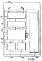
En référence avec la FIG.5B dont la légende est au Tableau
II, un système de contrôle 100 est couplé à une batterie
rechargeable 110, pour constituer un système global appelé
batterie intelligente 120. Cette batterie rechargeable a des
phases de charge alternant avec des phases de décharge selon
des cycles de décharge-charge consécutifs. Le système 100
contrôle les phases de décharge et éventuellement de charge
des cycles de décharge-charge de la batterie rechargeable. Ce
système de contrôle 100 comprend un calculateur 160 pour
fournir une indication d'un instant tTH où, dans une phase de
décharge, la batterie 110 atteindra un seuil critique
prédéterminé de tension VTH et plus spécifiquement, pour
fournir une indication du laps de temps ΔTTH restant a courir,
avant que ce seuil critique prédéterminé de tension de
décharge VTH ne soit atteint, ou bien les deux indications.With reference to FIG.5B, the legend of which is in Table II, a
L'ensemble de cette batterie intelligente 120 peut être
incorporée dans, ou couplée à ce dispositif hôte 130. Dans ce
cas, cette batterie rechargeable 110 est
couplée par des
connexions D1, D2 à ce dispositif hôte 130. Le dispositif hôte
comprend en outre des moyens d'affichage 140, pour fournir à
l'utilisateur les indications de temps tTH ou ΔTH, ou les deux.The whole of this
Le système de contrôle 100 est aussi couplé à des moyens
de mesure 150 du temps, et de la tension de batterie.The
En référence avec la FIG.1A, qui représente le système
de contrôle fonctionnant dans une phase de décharge de la batterie,
ce système de contrôle 100 collecte d'une part des valeurs appelées
initiales, à un instant appelé instant initial to, qui coïncide avec
le tout début d'une phase de décharge de la batterie dans un cycle
de décharge-charge. Ces valeurs initiales sont :
Ce système 100 peut collecter d'autre part des valeurs
instantanées à chaque instant courant successif t de cette même
phase de décharge. Ces valeurs instantanées sont :
En référence avec la FIG.1A, un système 100 de contrôle
des cycles de décharge-charge d'une batterie rechargeable 110
comprend des premier, second et troisième moyens de calcul
prédictifs et adaptatifs couplés notés respectivement NN1, NN2, et
NN3, pour fournir, à partir des valeur initiales de tension Vo, ΔVo,
No mesurées dans une phase de décharge, et à partir de la valeur
fixée d'un seuil de tension critique VTH, l'indication prédictive
d'un instant appelé instant critique tTH où, dans la même phase de
décharge, la tension de batterie atteindra ce seuil critique VTH, et
plus spécifiquement, une indication prédictive du laps de temps ΔtTH
restant à courir avant que ce seuil critique de tension de décharge
VTH ne soit atteint, ce seuil étant prédéterminé pour que, avant que
la tension de batterie n'atteigne ce seuil VTH, la batterie 110
conserve une énergie de fonctionnement précisément connue, et située
dans une certaine fourchette où cette énergie est correctement
adaptée au fonctionnement d'un dispositif hôte 130 qu'elle alimente. With reference to FIG. 1A, a
Tel que représenté sur la FIG.1A, dans un mode de réalisation, les premier, second et troisième moyens de calcul prédictifs et adaptatifs du système de contrôle 100 sont respectivement constitués par un premier réseau de neurones référencé NN1, un second réseau de neurones référencé NN2 monté en série avec le premier réseau de neurones NN1, et un troisième réseau de neurones NN3 monté en parallèle sur le deuxième réseau de neurones.As shown in FIG.1A, in a mode of realization, the first, second and third means of calculation predictive and adaptive 100 control systems are respectively constituted by a first neural network referenced NN1, a second neural network referenced NN2 mounted in series with the first neural network NN1, and a third network of NN3 neurons mounted in parallel on the second network of neurons.
Dans la description ci-après, une première phase de décharge, notée PD1, commençant à un instant to dans un cycle de décharge-charge, est d'abord considérée ; et un seuil critique prédéterminé de tension de décharge VTH est fixé.In the description below, a first discharge phase, denoted PD1, starting at an instant to in a discharge-charge cycle, is first considered; and a predetermined critical discharge voltage threshold V TH is fixed.
Le premier réseau de neurones NN1 a une entrée pour :
En référence avec la FIG.5A dont la légende est au
Tableau I, le premier réseau de neurones NN1 est couplé à des moyens
de mesure du temps 150a, qui fournissent une mesure de chaque
instant courant t, et est couplé au calculateur 160 qui a une
fonction d'additionneur et qui fournit par différence entre
l'instant courant t et la valeur calculée de l'instant tTH :
Dans ce mode de réalisation exemplatif, les coefficients synaptiques ou poids de ce premier réseau de neurones NN1 sont au nombre de 13 et sont référencée WjA où "j" est un indice de 1 à 13. Ils sont appelés premier paramètres WjA et sont calculés et fournis automatiquement durant cette première phase de décharge PD1, par le second réseau de neurones NN2 coopérant avec le troisième réseau de neurones NN3. In this exemplary embodiment, the coefficients synaptics or weights of this first NN1 neural network are at number of 13 and are referenced WjA where "j" is an index from 1 to 13. They are called the first WjA parameters and are calculated and supplied automatically during this first PD1 discharge phase, by the second network of NN2 neurons cooperating with the third network of NN3 neurons.
Le second réseau de neurones NN2 a 3 entrées
pour :
Le troisième réseau de neurones NN3 a les mêmes entrées
que le second réseau de neurones NN2, c'est-à-dire à trois entrées
pour :
Le calculateur 160, qui a une fonction d'additionneur,
fournit, entre autres, la valeur de la variation initiale de tension
Δto en calculant la différence entre la tension initiale Vo mesurée
à l'instant to, et une tension ultérieure V'o à l'instant suivant
t'o, telle que ΔVo = Vo - V'o.The
Ce calculateur 160 fournit en outre, dans sa fonction
d'additionneur, les coefficients synaptiques ou poids WjA
nécessaires au fonctionnement du premier réseau de neurone durant
cette première phase de décharge PD1, en effectuant l'addition des
paramètres approximatifs WjB issus du second réseau de neurones et
des paramètres de correction WjC issus du troisième réseau de
neurones.This
Les 13 résultats respectifs WjA = WjB + WjC sont imposés au premier réseau de neurones pendant cette première phase de décharge PD1, comme premiers paramètres de fonctionnement.The 13 respective results WjA = WjB + WjC are imposed to the first neural network during this first phase of discharge PD1, as the first operating parameters.
En référence avec la FIG.5B dont la légende est au
Tableau II, le système de contrôle comprend en outre des zones
de mémoire vive RAM 170b pour enregistrer ou fournir selon le cas,
les mesures variables et les poids du premier et du troisième réseau
de neurones, et une zone de mémoire morte ROM 170a pour stocker les
données de structures des réseaux de neurones NN1, NN2 et NN3, les
paramètres fixes et les poids du second réseau de neurones NN2.With reference to FIG.5B whose legend is at
Table II, the control system further includes
Ces mémoires sont accessibles par le calculateur 160,
lequel effectue les calculs nécessaires au fonctionnement du système
de contrôle 100.These memories are accessible by the
Chacun des réseaux de neurones NN1, NN2 et NN3 doivent être organisés (ou arrangés) pour mener à bien ces calculs et fournir ces sorties. A cet effet, chacun d'eux est soumis à une procédure d'apprentissage et à une procédure de test appelées phases d'entraínement pendant lesquelles leurs coefficients synaptiques sont déterminés et, dans certains cas, fixés.Each of the neural networks NN1, NN2 and NN3 must be organized (or arranged) to carry out these calculations and provide these outputs. To this end, each of them is subject to a learning procedure and a test procedure called phases during which their synaptic coefficients are determined and, in some cases, fixed.
La tâche du premier réseau de neurones NN1 est
d'apprendre des modèles de courbes de décharge. Cet apprentissage
permet de construire une relation entre la valeur instantanée de la
tension de décharge de batterie notée Vt, et l'instant courant t où
la batterie atteint cette tension Vt. Le premier réseau de neurones
NN1 doit, lors de son apprentissage, construire des fonctions Fw qui
résolvent la relation (1a) :
Le réseau de neurones NN1 a été construit pour générer une fonction Fw non linéaire.The NN1 neural network was built to generate a nonlinear function Fw.
En référence avec la FIG.2A, le premier réseau de
neurones NN1 comprend :
Donc, on remarque que, durant la procédure d'apprentissage du premier réseau de neurones NN1, son entrée NE1A collecte une valeur de tension instantanée Vt, alors que cette même entrée collecte la valeur de seuil critique de tension VTH lors de l'usage courant.So, we note that, during the learning procedure of the first neural network NN1, its input NE1A collects an instantaneous voltage value Vt, while this same input collects the critical voltage threshold value V TH during use current.
La structure et l'équation de fonctionnement de chaque neurone caché, noté NC1A à NC4A, sont celles d'un neurone formel "standard", et sont illustrées par la FIG.6A, qui montre la cellule cachée NC1A, à titre d'exemple.The structure and operating equation of each hidden neuron, noted NC1A to NC4A, are those of a formal neuron "standard", and are illustrated in FIG.6A, which shows the cell hidden NC1A, for example.
Chaque neurone caché donné NCiA reçoit d'une part en
entrée la tension instantanée Vt avec un poids, ou coefficient
synaptique d'entrée, qui est l'un des 13 poids référencé WjA, et
reçoit d'autre part un seuil ayant pour valeur la constante "-1",
affecté d'un autre des 13 poids référencé WjA. L'indice "i" est
l'indice 1 à 4 de la cellule neuronale cachée NC1A à NC4A concernée.
Chaque neurone caché NCiA réalise une somme pondérée, notée Σ, des
entrées affectées d'un des poids WjA, et calcule une sortie
intermédiaire Ei(Vt).Each hidden neuron given NCiA receives on the one hand
input the instantaneous voltage Vt with a weight, or coefficient
input synaptic, which is one of the 13 weights referenced WjA, and
receives on the other hand a threshold having for value the constant "-1",
affected by another of the 13 weights referenced WjA. The index "i" is
the
Chaque neurone caché NC1A à NC4A transfère cette sortie
intermédiaire Ei(Vt), à travers une fonction d'activation notée Si,
et il calcule une sortie notée Si(Vt) selon la relation (2a) :
Il reste alors à mieux définir la fonction d'activation Si(Vt) de chaque neurone caché. On peut adopter comme fonction d'activation possible, une fonction choisie dans l'ensemble des fonctions non linéaires.It remains to better define the activation function If (Vt) of each hidden neuron. We can adopt as function possible activation, a function chosen from all nonlinear functions.
La fonction d'activation Si est de préférence une fonction sigmoïde "tanh" égale à la fonction tangente hyperbolique, qui est très bien adaptée à la forme des courbes de décharge à construire, comme on le montrera ultérieurement. Dans la couche cachée, les 4 cellules neuronales NC1A à NC4A montrent donc dans l'exemple décrit, une fonction non linéaire "tanh".The activation function Si is preferably a sigmoid function "tanh" equal to the hyperbolic tangent function, which is very well suited to the shape of the discharge curves to build, as will be shown later. In the diaper hidden, the 4 neuronal cells NC1A to NC4A therefore show in the example described, a non-linear function "tanh".
La structure de l'unique neurone de sortie NSA est illustrée par la FIG.6B. Il réalise une somme pondérée, notée Σ, des sorties Si(Vt) de tous les neurones cachés NCiA, en utilisant des coefficients synaptiques WjA, somme à laquelle s'ajoute la valeur d'un seuil "-1" provenant de la cellule cachée NCOA, cette valeur de seuil étant introduite dans le neurone de sortie NSA à travers l'un des coefficients synaptiques WjA.The structure of the single NSA output neuron is illustrated in FIG. 6B. He realizes a weighted sum, noted Σ, of Si (Vt) outputs of all hidden NCiA neurons, using synaptic coefficients WjA, sum plus the value of a threshold "-1" coming from the hidden cell NCOA, this value of threshold being introduced into the NSA output neuron through one synaptic coefficients WjA.
Ce neurone de sortie effectue donc d'abord la somme pondérée Σ qui donne une sortie intermédiaire Es(Vt).This output neuron therefore first performs the sum weighted Σ which gives an intermediate output Es (Vt).
Puis, le neurone de sortie NSA transfère cette sortie
intermédiaire Es(Vt), à travers une fonction d'activation notée Ls,
et il calcule une sortie finale notée Fw(Vt) selon la ,
relation (3a) :
La fonction d'activation Ls de ce neurone de sortie est choisie linéaire. La sortie du neurone de sortie est la fonction Fw que l'on cherche à générer.The Ls activation function of this output neuron is chosen linear. The output of the output neuron is the function Fw that we are trying to generate.
Les notations des poids de chaque neurone caché NCiA
sont indiqués sur la FIG.2A, ainsi que les notations des poids
d'entrée du neurone de sortie NSA. L'ensemble de ces poids notés W1A
à W13A est formé par l'ensemble des 13 poids WjA transmis par les
second et troisième réseaux de neurones NN2 et NN3 montés en
parallèle dont les sorties sont couplées par le calculateur 160 à
fonction d'additionneur.The weight ratings of each hidden NCiA neuron
are shown in FIG. 2A, as well as the notations of the weights
input from the NSA output neuron. All of these weights noted W1A
to W13A is formed by the set of 13 weights WjA transmitted by the
second and third neural networks NN2 and NN3 mounted in
parallel whose outputs are coupled by the
En référence avec la FIG.4A, une courbe conventionnelle de décharge d'une batterie cadmium-nickel prise à titre d'exemple, donne la tension instantanée Vt en volt en fonction du temps t en minutes. Cette courbe montre une forte pente dans la première période de fonctionnement de la batterie, par exemple les 100 premières minutes, puis une pente faible entre 100 et 500 minutes d'utilisation, et enfin à nouveau une forte pente au-delà de 500 minutes. Bien entendu, cette courbe de décharge est donnée tout à fait à titre d'exemple.Referring to FIG.4A, a conventional curve discharge of a cadmium-nickel battery taken by way of example, gives the instantaneous voltage Vt in volts as a function of time t in minutes. This curve shows a steep slope in the first battery run time, for example 100 first minutes, then a slight slope between 100 and 500 minutes of use, and finally again a steep slope beyond 500 minutes. Of course, this discharge curve is given quite done as an example.
Mais, dans le présent système, on rappelle que le premier réseau de neurones NN1 doit subir un apprentissage conduisant à fournir un temps t qui est une fonction Fw de la tension Vt de la batterie.But, in the present system, it is recalled that the first neural network NN1 must undergo training leading to supply a time t which is a function Fw of the battery voltage Vt.
C'est pourquoi, un exemple de courbe de décharge qui intéresse la présente description est représenté sur la FIG.4B. Cette courbe montre le temps t en fonction de la tension de batterie Vt. Cette courbe de la FIG.4B est tracée simplement en portant les valeurs qui étaient en abscisse sur la FIG.4A, en ordonnée sur la FIG.4B ; et en portant les valeurs qui étaient en ordonnée sur la FIG.4A en abscisse sur la FIG.4B . On peut constater que cette courbe de décharge a une forme approchant la forme d'une courbe "tanh". C'est pourquoi, les fonctions du type des sigmoïdes sont préférées pour réaliser les fonctions d'activation dans les neurones de la couche cachée.This is why, an example of a discharge curve which of interest in this description is shown in FIG.4B. This curve shows the time t as a function of the battery voltage Vt. This curve of FIG. 4B is drawn simply by carrying the values which were on the abscissa on FIG. 4A, on the ordinate on the FIG.4B; and by carrying the values which were on the ordinate on the FIG.4A on the abscissa in FIG.4B. We can see that this discharge curve has a shape approaching the shape of a curve "Tanh". This is why the functions of the type of sigmoid are preferred for performing activation functions in neurons of the hidden layer.
La FIG.4B fournit donc une courbe de décharge donnant le temps t en minutes en fonction de la tension Vt en volt qui montre des parties extrêmes quasiment planes et une partie intermédiaire ayant une pente abrupte. C'est pourquoi, dans le premier réseau de neurones NN1, la modélisation de la partie intermédiaire des courbes de décharge de la relation (1a) est effectuée par les deux premières cellules neuronales NC1A, NC2A de la couche cachée, dont les fonctions d'activation ont respectivement une pente forte ; alors que la modélisation des parties extrêmes de ces courbes est effectuée par les cellules neuronales cachées suivantes NC3A, NC4A, qui montrent une fonction d'activation à pente moins forte.FIG. 4B therefore provides a discharge curve giving the time t in minutes as a function of the voltage Vt in volts which shows almost flat end portions and an intermediate portion having a steep slope. This is why, in the first network of NN1 neurons, modeling the intermediate part of the curves of discharge of the relation (1a) is carried out by the first two neuronal cells NC1A, NC2A of the hidden layer, whose activation functions respectively have a steep slope; so that the modeling of the extreme parts of these curves is performed by the following hidden neuronal cells NC3A, NC4A, which show a less steep activation function.
La présence de cellules cachées ayant des fonctions d'activation montrant des pentes très nettement différentes revient à spécialiser chaque cellule cachée dans la réalisation de taches différentes prédéterminées. Il est clair que le réseau de neurones NN1 pourrait apprendre la tâche de fournir la fonction Fw avec le même niveau de performance, sans que cette spécialisation existe. Mais, selon l'invention, il a été trouvé que la phase d'apprentissage du réseau de neurones NN1 se trouve considérablement raccourcie du fait que chaque cellule est dédiée à une tâche prédéterminée.The presence of hidden cells with functions activation showing very distinctly different slopes returns to specialize each hidden cell in carrying out tasks different predetermined. It is clear that the neural network NN1 could learn the task of providing the Fw function with the same level of performance, without this specialization existing. However, according to the invention, it has been found that the phase learning the NN1 neural network is found considerably shortened by the fact that each cell is dedicated to a task predetermined.
Les pentes des fonctions d'activation Si des cellules cachées NC1A, NC2A peuvent être par exemple 7.0, et les pentes de fonctions d'activation des cellules cachées suivantes NC2A, NC4A peuvent être par exemple 2.0. The slopes of the activation functions If cells hidden NC1A, NC2A can be for example 7.0, and the slopes of activation functions of the following hidden cells NC2A, NC4A can be for example 2.0.
Pour l'apprentissage du premier réseau de neurones NN1, des courbes de temps t de décharge en fonction de la tension V(t) de décharge sont enregistrées par exemple toutes les minutes pour un grand nombre N de cycles de décharge, et pour un grand nombre de batteries 110 du même type, par exemple des batteries cadmium-nickel.For learning the first neural network NN1, discharge time t curves as a function of the voltage V (t) of discharge are recorded for example every minute for a large number N of discharge cycles, and for a large number of 110 batteries of the same type, for example batteries nickel-cadmium.
Dans un exemple, 20 batteries sont utilisées, et subissent 140 cycles de décharge-charge. Une batterie est considérée comme totalement chargée quand sa tension Vo est de 9V, et est considérée comme ayant atteint le seuil critique de décharge quand sa tension atteint VTH = 6V. Par cette méthode, 20 x 140 = 2800 courbes de décharge sont enregistrées, de telle manière que chaque courbe fournit 1600 points.In one example, 20 batteries are used, and undergo 140 discharge-charge cycles. A battery is considered to be fully charged when its voltage Vo is 9V, and is considered to have reached the critical discharge threshold when its voltage reaches V TH = 6V. By this method, 20 x 140 = 2800 discharge curves are recorded, so that each curve provides 1600 points.
Chaque courbe est enseignée à un réseau NN1 différent. Ainsi dans la phase d'apprentissage, 2800 réseaux sont initialisés, c'est-à-dire 1 réseau par courbe. Dans chaque courbe, par exemple la moitié des points, c'est-à-dire 800 points, est utilisée pour l'apprentissage du réseau de neurone NN1 correspondant et, l'autre moitié des points, c'est-à-dire 800 autres points, est utilisée pour tester ledit réseau de neurones NN1.Each curve is taught to a different NN1 network. So in the learning phase, 2800 networks are initialized, that is to say 1 network per curve. In each curve, for example the half of the points, i.e. 800 points, is used to learning the corresponding neural network NN1 and, the other half of the points, i.e. 800 other points, is used to test said neural network NN1.
A l'issue de cet entraínement comprenant la phase d'apprentissage et les tests, les 13 poids WjA de chacun des 2800 réseaux de neurones NN1 sont mémorisés dans une zone de mémoire vive RAM, référencée 170b sur la FIG.5B.At the end of this training including the phase learning and testing, the 13 WjA weights of each of the 2800 NN1 neural networks are stored in a RAM area RAM, referenced 170b in FIG.5B.
A partir de là, les valeurs des lots de 13 poids WjA en mémoire vont constituer une base de données pour l'apprentissage du second réseau de neurones NN2.From there, the values of the batches of 13 WjA weights in memory will constitute a database for learning the second NN2 neural network.
La tâche du second réseau de neurones NN2 est
d'apprendre une relation entre des paramètres dépendant de la
tension de décharge de la batterie. Ainsi, le second réseau de
neurones NN2 reçoit :
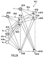
En référence avec la FIG.2B, la structure du second
réseau de neurones NN2 est dictée par sa tâche. Ce réseau de
neurones NN2 comprend :
Selon l'invention, les entrées constituées par les valeurs initiales Vo et ΔVo ont été spécifiquement choisies parce qu'il est apparu que c'était les valeurs les plus sensibles aux caractéristiques de la batterie.According to the invention, the inputs constituted by the initial values Vo and ΔVo were specifically chosen because that it appeared that these were the values most sensitive to battery characteristics.
La troisième entrée constituée par le nombre initial No de cycles a été également spécifiquement choisie parce qu'elle permet de prendre en compte un effet de vieillissement de la batterie, du fait que plus une batterie a subi de cycles de décharge-charge, moins il lui reste de temps de vie, c'est-à-dire moins l'effet de la recharge est efficace et plus le temps de décharge est rapide. Cet effet de vieillissement est illustré par la FIG.4C, qui montre en γ, des points mesurés correspondant au temps de décharge tTH pour atteindre le seuil critique VTH à partir de l'instant initial to, en fonction du nombre initial de cycles No. Ces mesures γ montrent que plus le nombre de cycles déjà effectués est grand, plus le temps de décharge tTH est court.The third entry, consisting of the initial number No of cycles, was also specifically chosen because it takes account of an aging effect of the battery, since the more a battery has undergone discharge-charge cycles, the less it it has life time left, that is to say the less the effect of the recharge is effective and the faster the discharge time. This aging effect is illustrated by FIG. 4C, which shows in γ, measured points corresponding to the discharge time t TH to reach the critical threshold V TH from the initial instant to, as a function of the initial number of cycles No. These γ measurements show that the greater the number of cycles already performed, the shorter the discharge time t TH .
Les coefficients synaptiques ou poids, référencés WnB de ce second réseau de neurones sont fixés lors de sa phase d'apprentissage et sont mis en mémoire dans la zone de mémoire morte ROM 170a, représentée sur la FIG.5B.Synaptic coefficients or weights, referenced WnB of this second neural network are fixed during its phase and are stored in the ROM area ROM 170a, shown in FIG.5B.
Des essais appliqués au réseau de neurones NN2 ont montré qu'un tel réseau muni de 8 cellules cachées, ayant pour fonction d'activation une fonction non linéaire tangente hyperbolique "tanh" est capable de mener à bien la tache qui lui est assignée.Tests applied to the NN2 neural network have shown that such a network with 8 hidden cells, having for activation function a tangent nonlinear function hyperbolic "tanh" is able to carry out his task assigned.
Il faut noter que, à la différence de la cellule de sortie NSA du premier réseau de neurone, les cellules de sortie, notées NS1B à NS13B du second réseau de neurone NN2 ont une fonction d'activation non linéaire, de préférence "tanh".It should be noted that, unlike the NSA output from the first neuron network, the output cells, noted NS1B to NS13B of the second neural network NN2 have a function non-linear activation, preferably "tanh".
Comme le premier réseau de neurones NN1, ce second réseau de neurones NN2 a des cellules cachées dont la pente de la fonction d'activation sigmoïde est différente d'une cellule à l'autre. Ce mode de réalisation permet de ne pas utiliser un nombre important de cellules cachées.Like the first neural network NN1, this second neural network NN2 has hidden cells whose slope of the sigmoid activation function is different from cell to cell the other. This embodiment allows not to use a number important hidden cell.
Ainsi, le second réseau de neurones NN2 est entraíné en utilisant 1400 vecteurs de 13 valeurs de poids générés par l'apprentissage du premier réseau de neurones NN1 au moyen des 2800 courbes enregistrées, et les 1400 autres vecteurs générés sont utilisés pour les tests.Thus, the second neural network NN2 is trained in using 1400 vectors of 13 weight values generated by learning the first neural network NN1 using the 2800 recorded curves, and the other 1400 generated vectors are used for testing.
La procédure de test est réalisée de la manière suivante : pour les 1400 vecteurs qui n'appartiennent pas au lot d'apprentissage, les valeurs initiales correspondantes Vo, ΔVo et No sont appliquées aux entrées du second réseau de neurones. Celui-ci calcule un vecteur de sortie de 13 valeurs de poids WjB comme il a été entraíné à le faire.The test procedure is carried out in the manner following: for the 1400 vectors which do not belong to the batch the corresponding initial values Vo, ΔVo and No are applied to the inputs of the second neural network. This one computes an output vector of 13 weight values WjB as it has been trained to do so.
Poursuivant cette procédure de test, ces 13 valeurs de poids WjB sont imposées à un réseau de neurone NN1, en même temps que la valeur critique prédéterminée de tension de décharge VTH = 6 volts est appliquée à son entrée NE1A. Ce premier réseau de neurone NN1 calcule alors la valeur prédictive automatiquement adaptée de temps de décharge tTH qui est comparée à celle de la courbe de test.Continuing this test procedure, these 13 weight values WjB are imposed on a neural network NN1, at the same time as the predetermined critical value of discharge voltage V TH = 6 volts is applied to its input NE1A. This first neural network NN1 then calculates the automatically adapted predictive value of discharge time t TH which is compared with that of the test curve.
En référence avec la FIG. 4C, on montre en α, une courbe prédictive de temps de décharge en fonction du nombre de cycles No, ainsi obtenue.With reference to FIG. 4C, we show in α, a curve predictive discharge time as a function of the number of cycles No, thus obtained.
Dans la phase d'apprentissage décrite plus haut, on n'a pas tenu compte de la présence du troisième réseau de neurones NN3.In the learning phase described above, we did not ignored the presence of the third NN3 neural network.
En référence avec la FIG.4C, si ce troisième réseau de neurones NN3 n'est pas mis dans le circuit, la courbe a donnant l'indication prédictive du temps tTH de décharge en fonction du nombre de cycles No diffère d'une courbe s'appuyant sur les mesures réelles γ, c'est-à-dire que le système de contrôle fait une erreur moyenne d'environ 10 mn dans la détermination prédictive de l'instant tTH où la batterie atteindra le seuil de tension critique VTH.With reference to FIG. 4C, if this third neural network NN3 is not put in the circuit, the curve a giving the predictive indication of the time t TH of discharge as a function of the number of cycles No differs from a curve relying on the actual measurements γ, that is to say that the control system makes an average error of approximately 10 min in the predictive determination of the instant t TH when the battery will reach the critical voltage threshold V TH .
Il est donc important de corriger cette erreur affectant la détermination prédictive de cet instant tTH.It is therefore important to correct this error affecting the predictive determination of this instant t TH .
Cette erreur peut être corrigée en corrigeant les poids imposés pour le fonctionnement du premier réseau de neurones. Ceci est fait en ne fournissant pas directement au premier réseau de neurones NN1 les paramètres WjB calculés par le second réseau de neurones NN2, parce qu'ils sont approximatifs et entraínent l'erreur qu'on a citée. Ceci est donc fait en corrigeant respectivement ces paramètres approximatifs WjB par des paramètres de correction WjC, fournis par le troisième réseau de neurones NN3, et en nombre égal aux paramètres approximatifs WjB.This error can be corrected by correcting the weights imposed for the functioning of the first neural network. This is done by not directly providing the first network with neurons NN1 the parameters WjB calculated by the second network of NN2 neurons, because they are approximate and cause error that we cited. This is therefore done by correcting these respectively approximate WjB parameters by WjC correction parameters, provided by the third neural network NN3, and in equal number to approximate WjB parameters.
Pour aboutir aux meilleurs poids WjA du premier réseau
de neurones NN1, les paramètres approximatifs WjB et les paramètres
de correction WjC sont additionnés par le calculateur 160 dans sa
fonction d'additionneur et le résultat est imposé à ce premier
réseau de neurones NN1.To achieve the best WjA weights of the first network
of neurons NN1, the approximate parameters WjB and the parameters
correction WjC are added by the
En référence avec la FIG.1B, dans la phase d'apprentissage, le troisième réseau de neurones NN3 apprend à calculer ses propres coefficients synaptiques, ou poids, comme des valeurs adaptatives, pour lui permettre de calculer les paramètres de corrections WjB qui, additionnés aux paramètres approximatifs WjA fournis par le second réseau de neurones NN2, vont constituer les coefficients synaptiques ou poids les mieux adaptés au fonctionnement du premier réseau de neurones NN1. Ainsi, ce premier réseau de neurones NN1 munis de ces poids WjA adaptés pourra fournir, durant la décharge, une indication prédictive de l'instant critique tTH plus proche de la valeur réelle.With reference to FIG. 1B, in the learning phase, the third neural network NN3 learns to calculate its own synaptic coefficients, or weights, as adaptive values, to enable it to calculate the correction parameters WjB which, added to the approximate parameters WjA supplied by the second neural network NN2, will constitute the synaptic coefficients or weights best suited to the functioning of the first neural network NN1. Thus, this first network of neurons NN1 provided with these adapted weights WjA will be able to provide, during the discharge, a predictive indication of the critical instant t TH closer to the real value.
Par exemple, avec l'utilisation de ce troisième réseau de neurones, la différence entre l'indication prédictive β de tTH et la valeur mesurée γ est abaissée à environ 1 minute comme démontré par les courbes de la FIG.4C. Cela est un grand avantage dans l'obtention de la précision des indications prédictives, puisque le système de contrôle passe d'une erreur de 10 mn sur les environs 570 mn de durée d'une décharge, à 1 mn sur ces 570 mn.For example, with the use of this third neural network, the difference between the predictive indication β of t TH and the measured value γ is lowered to approximately 1 minute as demonstrated by the curves in FIG. 4C. This is a great advantage in obtaining the accuracy of predictive indications, since the control system goes from an error of 10 min over the 570 min duration of a discharge, to 1 min over these 570 min.
Le système de contrôle ainsi constitué devient donc d'une très grande précision.The control system thus formed therefore becomes very precise.
En référence avec la FIG.2C, le troisième réseau de
neurones NN3 reçoit :
En référence avec la FIG.2C, la structure du troisième
réseau de neurones NN3 est dictée par sa tâche. Ce réseau de
neurones NN3 comprend :
Le troisième réseau de neurones nécessite, pour son fonctionnement, 4 coefficients synaptiques en entrée et 13 coefficients synaptiques en sortie, soit en tout 17 coefficients synaptiques notés WkC, où k est un indice de 1 à 17.The third neural network requires, for its operation, 4 input synaptic coefficients and 13 synaptic coefficients at output, i.e. a total of 17 coefficients synaptics noted WkC, where k is an index from 1 to 17.
En référence avec la FIG.3, dont la légende est au
Tableau III, qui représente un diagramme de blocs illustrant le
déroulement de la procédure d'apprentissage du troisième réseau de
neurones. NN3, cette procédure comprend :
- le second réseau de neurones reçoit des valeurs initiales Vo, ΔVo, et No et calcule des paramètres approximatifs WjB,
- une zone de mémoire vive (RAM) 170 b enregistre des mesures
instantanées fournies, en référence avec la FIG.5A par des moyens de
mesure du temps 150a, et par des moyens de mesure de
tension 150b de la batterie rechargeable 110 ; ces mesures instantanées sont enregistrées à chaque instant courant de ladite première phase de décharge PD1, par exemple toutes les minutes, et comprennent la mesure de l'instant courant t et de la valeur de tension correspondante Vt.
- the second neural network receives initial values Vo, ΔVo, and No and calculates approximate parameters WjB,
- a random access memory area (RAM) 170 b records instantaneous measurements supplied, with reference to FIG.5A by time measurement means 150a, and by voltage measurement means 150b of the
rechargeable battery 110; these instantaneous measurements are recorded at each current instant of said first discharge phase PD1, for example every minute, and include the measurement of the current instant t and of the corresponding voltage value Vt.
Dans cette nouvelle phase de décharge PD2, les coefficients synaptiques adaptatifs WkC, où k est un nombre de 1 à 17, correspondant à la structure du troisième réseau de neurones, représentée sur la FIG.2C, qui ont été calculés pendant la phase de charge PC1 du cycle précédent, sont conservés pour une nouvelle détermination des coefficients synaptiques du premier réseau de neurones NN1, comme décrit précédemment, en procédure de fonctionnement du système de contrôle. In this new PD2 discharge phase, the adaptive synaptic coefficients WkC, where k is a number from 1 to 17, corresponding to the structure of the third neural network, shown in FIG. 2C, which were calculated during the phase of load PC1 of the previous cycle, are kept for a new determination of the synaptic coefficients of the first network of NN1 neurons, as described above, in the procedure of operation of the control system.
Avec ces coefficient synaptiques adaptatifs WkC ainsi calculés, le troisième réseau de neurones NN3 fournit dans cette nouvelle phase de décharge PD2, des paramètres de correction WjC particulièrement bien adaptés à la correction des paramètres approximatifs WjB fournis par le second réseau de neurones NN2.With these WkC adaptive synaptic coefficient as well calculated, the third neural network NN3 provides in this new PD2 discharge phase, WjC correction parameters particularly well suited for correcting parameters approximate WjB provided by the second neural network NN2.
Le calculateur 160 effectue cette correction en
réalisant l'addition WjB + WjC qui fournit des nouveaux coefficients
synaptiques mieux adaptés pour le premier réseau de neurones NN1
dans cette deuxième phase de décharge.The
Le système de contrôle 100 a trois modes opératoires
appelés mode d'initialisation, mode d'usage courant, et mode
adaptatif.The
Le mode d'initialisation est mis en oeuvre chaque fois
que la batterie 110 a terminé une procédure de charge d'un cycle de
décharge-charge, et qu'elle commence alors un nouveau cycle
commençant par une phase de décharge. Dès que la batterie 110 est
mise en service, la tension initiale Vo est aussitôt enregistrée.
Puis, à l'instant t'o, après qu'un très petit laps de temps
to - t'o = Δto s'est écoulé, de préférence exactement 1 minute, la
tension de batterie est à nouveau enregistrée donnant une valeur
notée V'o, et la différence de tension initiale Vo - V'o = ΔVo est
calculée, par exemple par le calculateur à fonction additionneur 160
montré sur les FIG.5A et 5B. Ensuite, les deux valeurs Vo et ΔVo, en
même temps que le nombre initial No des cycles déjà effectués,
nombre qui est calculé par incrémentation par le calculateur 160,
sont fournis à l'entrée du second réseau de neurones NN2 qui calcule
alors le vecteur de 13 valeurs de poids WjB à appliquer au premier
réseau de neurones NN1A.The initialization mode is implemented each time
that the
Le mode d'usage courant est mis en oeuvre pendant la
phase de décharge elle-même. Dans ce mode d'usage courant, la
tension instantanée Vt est mesurée et stockée toute les minutes pour
la réactualisation ultérieure des poids du troisième réseau de
neurones. Le laps de temps restant ΔtTH avant que la batterie
n'atteigne ce seuil critique prédéterminé de tension VTH = 6V est
calculé comme une différence entre un temps tTH et un temps t,
où tTH est la sortie du réseau NN1A quand son entrée est
mise à VTH = 6 V,
et où t est l'instant mesuré par les moyens de mesure
150a. Les indications de temps tTH ou de laps de temps ΔtTH sont donc
fournies toutes les minutes.
Le mode adaptatif est mis en oeuvre durant la phase de charge et
comprend le calcul de nouveaux poids synaptiques Wkc pour le
troisième réseau de neurones NN3, à partir de valeurs instantanées
réelles Vt, t imposées au premier réseau de neurones NN1, à partir
du calcul des paramètres réels WjA* et du calcul des paramètres
d'erreur WjC* reportés sur le troisième réseau de neurones NN3,
selon la procédure décrite plus haut en référence avec les FIG.1B et
FIG.3.The current usage mode is implemented during the discharge phase itself. In this commonly used mode, the instantaneous voltage Vt is measured and stored every minute for the subsequent updating of the weights of the third neural network. The time remaining Δt TH before the battery reaches this predetermined critical voltage threshold V TH = 6V is calculated as a difference between a time t TH and a time t,
where t TH is the output of the NN1A network when its input is set to V TH = 6 V,
and where t is the instant measured by the measuring means 150a. The indications of time t TH or of time lapse Δt TH are therefore provided every minute.
The adaptive mode is implemented during the charging phase and includes the calculation of new synaptic weights Wkc for the third neural network NN3, from real instantaneous values Vt, t imposed on the first neural network NN1, from the calculation real parameters WjA * and the calculation of the error parameters WjC * reported on the third neural network NN3, according to the procedure described above with reference to FIG.1B and FIG.3.
D'une manière générale, en référence avec la FIG.5A dont
la légende est au Tableau I, le système de contrôle 100 est mis en
oeuvre par un microprocesseur 160 pour réaliser les calculs, et des
zones mémoire 170a, 170b pour mémoriser les données. Ces zones
mémoire sont accessibles par le microprocesseur 160 et incluent une
zone mémoire de stockage ROM 170a pour stocker les données de
structure des réseaux de neurones NN1, NN2 et NN3, les paramètres
fixes et les poids WnB du second réseau de neurones, et une zone de
mémoire vive RAM 170b pour enregistrer ou fournir selon le cas les
mesures variables et les vecteurs de poids WjA, WjC, WjA*, WjC* du
premier et du troisième réseaux de neurones. Le microprocesseur 160
effectue les calculs nécessaires au fonctionnement du système de
contrôle.In general, with reference to FIG.5A whose
the legend is in Table I, the
En référence avec la FIG.5B, dont la légende est au
Tableau II, le système de contrôle 100 est couplé à des moyens
d'affichage 140 pour fournir à l'utilisateur une indication du temps
tTH ou bien du laps de temps ΔtTH restant à courir à partir d'un
instant courant t d'utilisation jusqu'à l'instant où la batterie
atteindra ce seuil de tension critique prédéterminé VtTH, ou bien les
deux indications. Les moyens d'affichage 140 peuvent en outre
afficher l'heure, c'est-à-dire une indication de l'instant courant ;
ces moyens d'affichage peuvent en outre afficher une indication à
l'issue de la phase de charge consécutive à la phase de décharge de
la batterie, que cette phase de charge est terminée, lorsque la
batterie a atteint la tension initiale Vo = 9V par exemple.With reference to FIG. 5B, the legend of which is in Table II, the
Comme cité précédemment, le système de contrôle 100 fait
partie d'un dispositif hôte 130 qui comprend des moyens de connexion
D1, D2 pour la batterie rechargeable 110. La batterie rechargeable
110 est couplée au système de contrôle 100 pour former la batterie
intelligente 120. Le dispositif hôte 130 abrite en outre les moyens
de mesure 150, par exemple un multimètre, le microprocesseur 160,
les zones mémoire 170a, 170b accessibles par le microprocesseur 160
et les moyens d'affichage 140.As mentioned above, the
Pour la réalisation des moyens d'affichage, plusieurs
dispositifs connus de l'état de la technique sont utilisables. Un
dispositif peut être un écran avec des indications écrites, ou avec
des indications dessinées, ou encore un panneau formée de diodes.

Claims (14)
- A monitoring system (100) for monitoring discharge/charge cycles of a battery intended to be coupled to a rechargeable battery (110) having charge periods which alternate with discharge periods depending on discharge/charge cycles, this system comprising:this system also comprising:first adaptive calculation means (NN1) which are arranged for collecting at the beginning of a discharge period of a discharge/charge cycle of the battery a batch of operating parameters called first parameters (WjA), and for receiving on the input a predetermined value of a critical discharge voltage threshold (VTH), and which are arranged for producing on the output a calculated predictive indication of the instant (tTH) at which the battery will reach this critical threshold (VTH) that corresponds to the end of this discharge period,second and third adaptive calculation means (NN2, NN3) coupled to the first calculation means, which are arranged for receiving on the input, at an initial instant, at the beginning of said discharge period of the battery, a value of the battery voltage called initial voltage (Vo), a value of a variation (ΔVo) of this initial voltage after a short lapse of time starting from this initial instant, and a value of the initial number (No) of discharge/charge cycles of this battery effected before said discharge period, and which are arranged for producing on the output from the instant of said discharge period at which the initial values are available, a batch of approximate parameters and a batch of corresponding correction parameters (WjC) respectively, which are added together to form said first operating parameters (WjA) imposed on said first calculation means (NN1)and a calculator that can be applied to said parameters.
- A monitoring system as claimed in claim 1, also comprising a read/write memory area (170b) for recording during said discharge period batches of instantaneous real values formed each by a discharge voltage measurement (Vt) of the battery and by the current instant (t) corresponding to this measurement,
the monitoring system being arranged so that during the battery charge period (PC1) following said discharge period (PD1) of the respective discharge/charge cycle:the first calculation means (NN1) are furthermore arranged for calculating a posteriori in an autonomous manner, and for producing parameters called real parameters (WjA*) which correspond to the operation of these first calculation means (NN1) in the situation when the batches of instantaneous real values are imposed on them, while the discharge voltage measurement (Vt) is imposed on the input and the corresponding current instant (t) is imposed on the output,the calculator (160) is arranged for receiving said approximate parameters (WjB) calculated by the second calculation means (NN2) during the discharge period (PD1), and said real parameters (WjA*) calculated by the first calculation means (NN1) during the charge period (PC1), and for producing respective differences between these parameters called error parameters (WjC*), andthe third calculation means (NN3) are arranged for calculating autonomously parameters called adaptive parameters (WkC) which correspond to the operation of these third calculation means in the situation when the error parameters (WjC*) are imposed on them, at the output, whereas the initial values (Vo, ΔVo, No) of the previous discharge period (PD1) are imposed on them, at the input,and in which system the third calculation means (NN3) are arranged so that the third calculation means (NN3) maintains as operating parameters in the later discharge period of the next discharge/charge cycle the adaptive parameters (WkC) calculated in said charge period (PC1). - A monitoring system as claimed in one of the claims 1 or 2, in which:the first, second and third calculation means (NN1, NN2, NN3) are formed by a first, second and third neural network respectively, the first operating parameters are the synaptic coefficients (WjA) of the first neural network, the first neural network (NN1) having an input cell (EC1A) for a voltage value and an output cell (NSA) for a time value,the second neural network having three input cells (NE1B, NE2B, NE3B) for said initial values (Vo, ΔVo, No) and a number of output cells (NS1B - NS13B) for the approximate parameters (WjB) which is equal to the number of synaptic coefficients (WjA) of the first neural network (NN1), andthe third neural network (NN3) having three input cells (NE1C, NE2C, NE3C) for said initial values (Vo, ΔVo, No) and a number of output cells (NS1C - NS13C) for the correction parameters (WjC) which is equal to the number of synaptic coefficients (WjA) of the first neural network (NN1), and in which monitoring system:the calculator (160) is arranged for receiving and adding together in the discharge period the approximate parameters (WjB) and the correction parameters (WjC) and for producing said synaptic coefficients (WjA) imposed on the first neural network (NN1).
- A monitoring system as claimed in claim 3, in which:the first neural network (NN1), which forms the first calculation means, is arranged for calculating during the charge period (PC1) that follows the discharge period (PD1) of the respective discharge/charge cycle, by a reverse propagation method, real parameters (WjA*) which are its own real synaptic coefficients, in the situation when for each batch of instantaneous real values the measurement of the discharge voltage (Vt) is imposed at its input, and the corresponding current instant (t) is imposed at its output,the calculator (160) is arranged for producing the error parameters (WjC*) formed by the respective differences between said real synaptic coefficients (WjA*) calculated by the first neural network (NN1) during said charge period (PC1), and said approximate parameters (WjB) calculated by the second neural network (NN2) for said previous discharge period (PD1),the third neural network (NN3) forming the third calculation means is arranged for calculating, via a reverse propagation method, the adaptive parameters (WkC) which are its own adaptive synaptic coefficients, in the situation when the error parameters (WkC*) are imposed on its outputs and the initial values (Vo, ΔVo, No) of the previous discharge period (PD1) are imposed on its inputs, andthis third neural network (NN3) in the subsequent discharge period (PD2) of the next discharge/charge cycle maintains these adaptive synaptic coefficients (WkC) calculated in said charge period.
- A monitoring system as claimed in one of the claims 1 or 2, in which:the calculator (160) is also arranged for calculating and producing at each current instant (t) on the basis of the measurement of this current instant (t) and on the basis of the predictive indication of the critical instant (tTH) produced by the first adaptive calculation means, a predictive indication of the lapse of time (ΔtTH) that is left from this current instant (t) onwards until the critical instant (tTH) at which the battery will reach the predetermined critical discharge voltage threshold (VTH).
- A monitoring system as claimed in one of the claims 3 or 4, in which:the calculator is also arranged for calculating and producing at each current instant (t) on the basis of the measurement of this current instant (t) and on the basis of the predictive indication of the critical instant (tTH) produced by the first neural network a predictive indication of the lapse of time (ΔtTH) that is left from this current instant (t) onwards until the critical instant (tTH) at which the battery will reach its predetermined critical discharge voltage threshold (VTH)·
- A monitoring system as claimed in any one of the claims 3, 4 or 6, in which the second neural network (NN2) is combined in series with the first neural network (NN1), and in which the third neural network (NN3) is combined in parallel with the second neural network.
- A monitoring system as claimed in claim 7, in which the first neural network (NN1) has three layers, of which one input layer of a neural cell (NE1A) for a voltage value has a hidden layer of neural cells and an output layer having a single neural cell (NSA), the cells of the hidden layer having a sigmoidal activating function with slopes varying from one cell to the next, and the cell of the output layer having a linear activating function.
- A monitoring system as claimed in claim 8, in which the second neural network (NN2) has three neural cell layers, of which one input layer of three neural cells (NE1B, NE2B, NE3B) for each of the initial values (Vo, ΔVo, No), one layer of hidden cells, and one output layer of neural cells (NS1B-NS13B), the cells of the hidden layer (NC1B-NC8B) having a sigmoidal activating function with different slopes from one cell to the next, and the number of cells of the output layer being equal to the number of synaptic coefficients which are necessary for the operation of the first neural network and having a sigmoidal activating function.
- A monitoring system as claimed in claim 9 in which the third neural network (NN3) has three neural cell layers, of which one input layer of three neural cells (ME1C, NE2C, NE3C) for each of the initial values (Vo, ΔVo, No), one layer of a single hidden cell (AU), and one output layer of neural cells (NS1C-NS13C), the number of cells of the output layer being equal to the number of synaptic coefficients necessary for the operation of the first neural network (NN1), and having a sigmoidal activating function.
- A monitoring system as claimed in any one of the claims 4 to 10, comprising a microprocessor (160) for performing the calculations to form the first, second and third neural networks, and the calculator, and memory areas (170a, 170b) for storing the data, these memory areas being accessible via the microprocessor (160) and including a memory area (170a) for storing the structure data of the neural networks, the fixed parameters and the synaptic coefficients of the second neural network, and a random access memory area (170b) for storing or producing the variable measurements, and the synaptic coefficients of the first and of the third neural networks.
- A monitoring system as claimed in any one of claims 1 to 11, this system (100) being coupled to a rechargeable battery (110), to time measuring means (150a), voltage measuring means (150b), and display means (140) arranged for producing either an indication of the critical instant (tTH) at which the battery will reach the critical voltage threshold (VtTH), or an indication of the lapse of time (ΔtTH) that is left from a current instant of use (t) onwards until the instant (tTH) at which the battery will reach a predetermined critical voltage threshold (VtTH), or the two indications, and possibly an indication of the end of the recharge period of the battery.
- A host device (130) fed by a rechargeable battery (110) and comprising a monitoring system (100) as claimed in claim 12, this host device being fed by the rechargeable battery (110) which is coupled to said monitoring system.
- A method of producing neural networks of the monitoring system as claimed in any one of the claims 7 to 12, comprising in a learning period:a method of use of the monitoring system comprising the use of said adaptive parameters (WkC) as synaptic coefficients of the third neural network (NN3) in the later discharge period of the next discharge/charge cycle.the learning by the first neural network, of discharge time curves (t) as a function of the discharge voltage (Vt) during which discharge voltages (Vt) are imposed on the input of the first neural network normally intended for the voltage value, and the corresponding instants (t) are imposed on the output for forming a data base formed by vectors of the synaptic coefficients (WjA) of this first neural network,the learning by the second neural network of relations between the initial values (Vo, ΔVo, No) and the synaptic coefficients (WjA) of the first neural network, determined in its learning procedure,the learning of the third neural network to make it determine its own adaptive synaptic coefficients (WkC), this learning comprising the steps of:1) in the discharge period (PD1) of a discharge/charge cycle of the battery, storing the initial values (Vo, ΔVo, No) and instantaneous real values of the battery voltage (Vt) as a function of the corresponding current instant (t), and approximate parameters (WjB) produced by the second neural network (NN2),2) in the subsequent charge period (PC1), this learning comprising the sub-steps of:2a) calculating by the first neural network its own real synaptic coefficients (WjA*) when the instantaneous voltage (Vt) and time (t) values are imposed on its input and on its output respectively,2b) calculating error parameters (WjC*) by calculating the differences between the real parameters (WjA*) and the approximate parameters (WjB),2c) calculating by the third neural network (NN3) its own synaptic coefficients (WkC) called adaptive parameters when the error parameters (WjC*) are imposed on its output and the initial values (Vo, ΔVo, No) are imposed on its inputs, and
Applications Claiming Priority (2)
| Application Number | Priority Date | Filing Date | Title |
|---|---|---|---|
| FR9512864 | 1995-10-31 | ||
| FR9512864A FR2740555A1 (en) | 1995-10-31 | 1995-10-31 | SYSTEM FOR MONITORING THE CHARGING-DISCHARGE CYCLES OF A RECHARGEABLE BATTERY, AND HOST DEVICE PROVIDED WITH AN INTELLIGENT BATTERY |
Publications (2)
| Publication Number | Publication Date |
|---|---|
| EP0772056A1 EP0772056A1 (en) | 1997-05-07 |
| EP0772056B1 true EP0772056B1 (en) | 2004-08-18 |
Family
ID=9484106
Family Applications (1)
| Application Number | Title | Priority Date | Filing Date |
|---|---|---|---|
| EP96202928A Expired - Lifetime EP0772056B1 (en) | 1995-10-31 | 1996-10-21 | System for controlling the charge/discharge cycles of a rechargeable battery and host device including an intelligent battery |
Country Status (5)
| Country | Link |
|---|---|
| US (1) | US5825156A (en) |
| EP (1) | EP0772056B1 (en) |
| JP (1) | JP3887047B2 (en) |
| DE (1) | DE69633162T2 (en) |
| FR (1) | FR2740555A1 (en) |
Families Citing this family (125)
| Publication number | Priority date | Publication date | Assignee | Title |
|---|---|---|---|---|
| US6351102B1 (en) | 1999-04-16 | 2002-02-26 | Midtronics, Inc. | Automotive battery charging system tester |
| US6566883B1 (en) | 1999-11-01 | 2003-05-20 | Midtronics, Inc. | Electronic battery tester |
| US6633165B2 (en) | 1997-11-03 | 2003-10-14 | Midtronics, Inc. | In-vehicle battery monitor |
| US8198900B2 (en) | 1996-07-29 | 2012-06-12 | Midtronics, Inc. | Automotive battery charging system tester |
| US6445158B1 (en) | 1996-07-29 | 2002-09-03 | Midtronics, Inc. | Vehicle electrical system tester with encoded output |
| US7706991B2 (en) | 1996-07-29 | 2010-04-27 | Midtronics, Inc. | Alternator tester |
| US8872517B2 (en) | 1996-07-29 | 2014-10-28 | Midtronics, Inc. | Electronic battery tester with battery age input |
| US6850037B2 (en) | 1997-11-03 | 2005-02-01 | Midtronics, Inc. | In-vehicle battery monitor |
| US5914605A (en) | 1997-01-13 | 1999-06-22 | Midtronics, Inc. | Electronic battery tester |
| US6456988B1 (en) | 1997-03-12 | 2002-09-24 | U.S. Nanocorp Inc. | Method for determining state-of-health using an intelligent system |
| CA2294144A1 (en) * | 1997-06-19 | 1998-12-23 | Snap-On Equipment Limited | Battery testing and classification |
| US8958998B2 (en) | 1997-11-03 | 2015-02-17 | Midtronics, Inc. | Electronic battery tester with network communication |
| US6586941B2 (en) | 2000-03-27 | 2003-07-01 | Midtronics, Inc. | Battery tester with databus |
| US7774151B2 (en) | 1997-11-03 | 2010-08-10 | Midtronics, Inc. | Wireless battery monitor |
| US7688074B2 (en) | 1997-11-03 | 2010-03-30 | Midtronics, Inc. | Energy management system for automotive vehicle |
| US7705602B2 (en) | 1997-11-03 | 2010-04-27 | Midtronics, Inc. | Automotive vehicle electrical system diagnostic device |
| US6835491B2 (en) | 1998-04-02 | 2004-12-28 | The Board Of Trustees Of The University Of Illinois | Battery having a built-in controller |
| US6163131A (en) * | 1998-04-02 | 2000-12-19 | The Procter & Gamble Company | Battery having a built-in controller |
| US6118248A (en) * | 1998-04-02 | 2000-09-12 | The Procter & Gamble Company | Battery having a built-in controller to extend battery service run time |
| US6198250B1 (en) | 1998-04-02 | 2001-03-06 | The Procter & Gamble Company | Primary battery having a built-in controller to extend battery run time |
| US6074775A (en) * | 1998-04-02 | 2000-06-13 | The Procter & Gamble Company | Battery having a built-in controller |
| WO2000007256A1 (en) | 1998-07-27 | 2000-02-10 | Gnb Technologies | Apparatus and method for carrying out diagnostic tests on batteries and for rapidly charging batteries |
| AU4333000A (en) | 1999-04-08 | 2000-11-14 | Midtronics, Inc. | Electronic battery tester |
| US6795782B2 (en) | 1999-04-08 | 2004-09-21 | Midtronics, Inc. | Battery test module |
| US6456045B1 (en) | 1999-04-16 | 2002-09-24 | Midtronics, Inc. | Integrated conductance and load test based electronic battery tester |
| US6483275B1 (en) | 1999-04-23 | 2002-11-19 | The Board Of Trustees Of The Univesity Of Illinois | Consumer battery having a built-in indicator |
| US6359441B1 (en) | 1999-04-30 | 2002-03-19 | Midtronics, Inc. | Electronic battery tester |
| GB2350686B (en) * | 1999-06-03 | 2004-01-07 | Switchtec Power Systems Ltd | Battery capacity measurement |
| US6441585B1 (en) | 1999-06-16 | 2002-08-27 | Midtronics, Inc. | Apparatus and method for testing rechargeable energy storage batteries |
| US6490543B1 (en) * | 1999-07-13 | 2002-12-03 | Scientific Monitoring Inc | Lifeometer for measuring and displaying life systems/parts |
| US6313607B1 (en) | 1999-09-01 | 2001-11-06 | Keith S. Champlin | Method and apparatus for evaluating stored charge in an electrochemical cell or battery |
| US6737831B2 (en) | 1999-09-01 | 2004-05-18 | Keith S. Champlin | Method and apparatus using a circuit model to evaluate cell/battery parameters |
| US6363303B1 (en) * | 1999-11-01 | 2002-03-26 | Midtronics, Inc. | Alternator diagnostic system |
| DE19959019A1 (en) * | 1999-12-08 | 2001-06-13 | Bosch Gmbh Robert | Method for status detection of an energy store |
| US6252378B1 (en) | 2000-01-10 | 2001-06-26 | Snap-On Technologies, Inc. | Usage counter for portable jump-starting battery unit |
| US6466025B1 (en) | 2000-01-13 | 2002-10-15 | Midtronics, Inc. | Alternator tester |
| US6928371B1 (en) * | 2000-02-08 | 2005-08-09 | Paul T. Roshau | Monitoring system of VRLA battery capacitance |
| DE10012964A1 (en) * | 2000-03-16 | 2001-10-04 | Implex Hear Tech Ag | Device for operating re-chargeable electrical energy storage device selects current charging strategy for storage device depending on prognosis derived from model, storage device parameters |
| US6759849B2 (en) | 2000-03-27 | 2004-07-06 | Kevin I. Bertness | Battery tester configured to receive a removable digital module |
| US7446536B2 (en) | 2000-03-27 | 2008-11-04 | Midtronics, Inc. | Scan tool for electronic battery tester |
| US8513949B2 (en) | 2000-03-27 | 2013-08-20 | Midtronics, Inc. | Electronic battery tester or charger with databus connection |
| US7398176B2 (en) | 2000-03-27 | 2008-07-08 | Midtronics, Inc. | Battery testers with secondary functionality |
| AU2001290370A1 (en) | 2000-09-04 | 2002-03-22 | Invensys Energy Systems (Nz) Limited | Battery monitoring network |
| AU2001290371A1 (en) * | 2000-09-04 | 2002-03-22 | Invensys Energy Systems (Nz) Limited | Battery monitoring |
| US6784641B2 (en) * | 2000-09-20 | 2004-08-31 | Toshiba Battery Co., Ltd. | Uninterruptible power supply |
| US6628102B2 (en) * | 2001-04-06 | 2003-09-30 | Microchip Technology Inc. | Current measuring terminal assembly for a battery |
| US7205746B2 (en) * | 2001-04-06 | 2007-04-17 | Microchip Technology Inc. | Battery cover assembly having integrated battery condition monitoring |
| GB2413225B (en) * | 2001-05-14 | 2005-12-28 | Eaton Power Quality Ltd | Battery charge management |
| US6417669B1 (en) | 2001-06-11 | 2002-07-09 | Keith S. Champlin | Suppressing interference in AC measurements of cells, batteries and other electrical elements |
| US6788025B2 (en) | 2001-06-22 | 2004-09-07 | Midtronics, Inc. | Battery charger with booster pack |
| US6544078B2 (en) | 2001-07-18 | 2003-04-08 | Midtronics, Inc. | Battery clamp with integrated current sensor |
| US6469511B1 (en) | 2001-07-18 | 2002-10-22 | Midtronics, Inc. | Battery clamp with embedded environment sensor |
| US7111179B1 (en) | 2001-10-11 | 2006-09-19 | In-Hand Electronics, Inc. | Method and apparatus for optimizing performance and battery life of electronic devices based on system and application parameters |
| US6466026B1 (en) | 2001-10-12 | 2002-10-15 | Keith S. Champlin | Programmable current exciter for measuring AC immittance of cells and batteries |
| US6696819B2 (en) | 2002-01-08 | 2004-02-24 | Midtronics, Inc. | Battery charge control device |
| US7723993B2 (en) | 2002-09-05 | 2010-05-25 | Midtronics, Inc. | Electronic battery tester configured to predict a load test result based on open circuit voltage, temperature, cranking size rating, and a dynamic parameter |
| US6781382B2 (en) | 2002-12-05 | 2004-08-24 | Midtronics, Inc. | Electronic battery tester |
| US7199557B2 (en) * | 2003-07-01 | 2007-04-03 | Eaton Power Quality Company | Apparatus, methods and computer program products for estimation of battery reserve life using adaptively modified state of health indicator-based reserve life models |
| US9018958B2 (en) | 2003-09-05 | 2015-04-28 | Midtronics, Inc. | Method and apparatus for measuring a parameter of a vehicle electrical system |
| US7154276B2 (en) | 2003-09-05 | 2006-12-26 | Midtronics, Inc. | Method and apparatus for measuring a parameter of a vehicle electrical system |
| US9255955B2 (en) | 2003-09-05 | 2016-02-09 | Midtronics, Inc. | Method and apparatus for measuring a parameter of a vehicle electrical system |
| US8164343B2 (en) | 2003-09-05 | 2012-04-24 | Midtronics, Inc. | Method and apparatus for measuring a parameter of a vehicle electrical system |
| US7977914B2 (en) | 2003-10-08 | 2011-07-12 | Midtronics, Inc. | Battery maintenance tool with probe light |
| US7772850B2 (en) | 2004-07-12 | 2010-08-10 | Midtronics, Inc. | Wireless battery tester with information encryption means |
| US9496720B2 (en) | 2004-08-20 | 2016-11-15 | Midtronics, Inc. | System for automatically gathering battery information |
| US8442877B2 (en) | 2004-08-20 | 2013-05-14 | Midtronics, Inc. | Simplification of inventory management |
| US8436619B2 (en) | 2004-08-20 | 2013-05-07 | Midtronics, Inc. | Integrated tag reader and environment sensor |
| US8344685B2 (en) | 2004-08-20 | 2013-01-01 | Midtronics, Inc. | System for automatically gathering battery information |
| US7710119B2 (en) | 2004-12-09 | 2010-05-04 | Midtronics, Inc. | Battery tester that calculates its own reference values |
| DE602006002896D1 (en) * | 2005-02-14 | 2008-11-13 | Denso Corp | Method and device for detecting the charging status of a secondary battery based on neural network calculation |
| US7197487B2 (en) * | 2005-03-16 | 2007-03-27 | Lg Chem, Ltd. | Apparatus and method for estimating battery state of charge |
| JP4587306B2 (en) * | 2005-04-20 | 2010-11-24 | 株式会社デンソー | Secondary battery remaining capacity calculation method |
| US7504801B2 (en) * | 2006-06-30 | 2009-03-17 | Cisco Technology, Inc. | Systems and methods of profiling power cycles in a battery for indicating detrimental battery operation |
| GB2444511B (en) * | 2006-12-06 | 2008-10-22 | Iti Scotland Ltd | Battery Management System |
| US7791348B2 (en) | 2007-02-27 | 2010-09-07 | Midtronics, Inc. | Battery tester with promotion feature to promote use of the battery tester by providing the user with codes having redeemable value |
| US7808375B2 (en) | 2007-04-16 | 2010-10-05 | Midtronics, Inc. | Battery run down indicator |
| CN101067644B (en) * | 2007-04-20 | 2010-05-26 | 杭州高特电子设备有限公司 | Storage battery performance analytical expert diagnosing method |
| US9274157B2 (en) | 2007-07-17 | 2016-03-01 | Midtronics, Inc. | Battery tester for electric vehicle |
| GB2463829B (en) | 2007-07-17 | 2012-11-21 | Midtronics Inc | Battery tester for electric vehicle |
| JP2009049005A (en) * | 2007-07-26 | 2009-03-05 | Panasonic Corp | Device and method for battery internal short circuit detection, battery pack, and electronic device system |
| KR100911316B1 (en) * | 2007-08-23 | 2009-08-11 | 주식회사 엘지화학 | System and method for estimating of batteries's long term characteristics |
| KR100936892B1 (en) * | 2007-09-13 | 2010-01-14 | 주식회사 엘지화학 | System and method for estimating of batteries´s long term characteristics |
| US8203345B2 (en) | 2007-12-06 | 2012-06-19 | Midtronics, Inc. | Storage battery and battery tester |
| US20100174642A1 (en) * | 2009-01-07 | 2010-07-08 | Better Energy Systems Ltd. | Solar powered utility |
| US8330425B2 (en) * | 2009-10-19 | 2012-12-11 | Verizon Patent And Licensing Inc. | System for and method of detecting a non-functional battery back-up unit (BBU) of an optical network terminal |
| US20110193518A1 (en) * | 2010-02-10 | 2011-08-11 | James Wright | Battery override |
| US9588185B2 (en) | 2010-02-25 | 2017-03-07 | Keith S. Champlin | Method and apparatus for detecting cell deterioration in an electrochemical cell or battery |
| WO2011109343A2 (en) | 2010-03-03 | 2011-09-09 | Midtronics, Inc. | Monitor for front terminal batteries |
| US9229062B2 (en) | 2010-05-27 | 2016-01-05 | Midtronics, Inc. | Electronic storage battery diagnostic system |
| US10046649B2 (en) | 2012-06-28 | 2018-08-14 | Midtronics, Inc. | Hybrid and electric vehicle battery pack maintenance device |
| KR20130030766A (en) | 2010-06-03 | 2013-03-27 | 미드트로닉스, 인크. | Battery pack maintenance for electric vehicles |
| US11740294B2 (en) | 2010-06-03 | 2023-08-29 | Midtronics, Inc. | High use battery pack maintenance |
| US8738309B2 (en) | 2010-09-30 | 2014-05-27 | Midtronics, Inc. | Battery pack maintenance for electric vehicles |
| US9419311B2 (en) | 2010-06-18 | 2016-08-16 | Midtronics, Inc. | Battery maintenance device with thermal buffer |
| US9201120B2 (en) | 2010-08-12 | 2015-12-01 | Midtronics, Inc. | Electronic battery tester for testing storage battery |
| JP5565273B2 (en) * | 2010-10-29 | 2014-08-06 | 株式会社豊田自動織機 | Industrial vehicle |
| JP5875037B2 (en) | 2011-07-08 | 2016-03-02 | インターナショナル・ビジネス・マシーンズ・コーポレーションInternational Business Machines Corporation | Battery state prediction system, method and program |
| US9020649B2 (en) * | 2011-07-18 | 2015-04-28 | Nec Laboratories America, Inc. | Method for real-time power management of a grid-tied microgrid to extend storage lifetime and reduce cost of energy |
| JP5852399B2 (en) * | 2011-10-17 | 2016-02-03 | インターナショナル・ビジネス・マシーンズ・コーポレーションInternational Business Machines Corporation | Battery state prediction system, method and program |
| WO2013070850A2 (en) | 2011-11-10 | 2013-05-16 | Midtronics, Inc. | Battery pack tester |
| DE102012007988A1 (en) * | 2012-04-20 | 2013-10-24 | Volkswagen Aktiengesellschaft | Method for visualizing dynamic power of battery of electrically driven vehicle, involves determining power values of battery, where latter power value is higher than former power value |
| CN103427125B (en) * | 2012-05-15 | 2016-04-13 | 清华大学 | The round-robin method of sulfenyl polymer Li-ion battery |
| US11325479B2 (en) | 2012-06-28 | 2022-05-10 | Midtronics, Inc. | Hybrid and electric vehicle battery maintenance device |
| US9851411B2 (en) | 2012-06-28 | 2017-12-26 | Keith S. Champlin | Suppressing HF cable oscillations during dynamic measurements of cells and batteries |
| US9442165B2 (en) * | 2012-07-07 | 2016-09-13 | Nec Corporation | Method for estimating battery life in presence of partial charge and discharge cycles |
| US9244100B2 (en) | 2013-03-15 | 2016-01-26 | Midtronics, Inc. | Current clamp with jaw closure detection |
| US9312575B2 (en) | 2013-05-16 | 2016-04-12 | Midtronics, Inc. | Battery testing system and method |
| US10843574B2 (en) | 2013-12-12 | 2020-11-24 | Midtronics, Inc. | Calibration and programming of in-vehicle battery sensors |
| EP2897229A1 (en) | 2014-01-16 | 2015-07-22 | Midtronics, Inc. | Battery clamp with endoskeleton design |
| US10473555B2 (en) | 2014-07-14 | 2019-11-12 | Midtronics, Inc. | Automotive maintenance system |
| US10222397B2 (en) | 2014-09-26 | 2019-03-05 | Midtronics, Inc. | Cable connector for electronic battery tester |
| WO2016051722A1 (en) * | 2014-09-29 | 2016-04-07 | 日本電気株式会社 | Electric power storage device, control device, electric power storage system, method for controlling electric power storage device, and non-transitory computer-readable medium storing control program |
| WO2016123075A1 (en) | 2015-01-26 | 2016-08-04 | Midtronics, Inc. | Alternator tester |
| US9966676B2 (en) | 2015-09-28 | 2018-05-08 | Midtronics, Inc. | Kelvin connector adapter for storage battery |
| US10608353B2 (en) | 2016-06-28 | 2020-03-31 | Midtronics, Inc. | Battery clamp |
| US11054480B2 (en) | 2016-10-25 | 2021-07-06 | Midtronics, Inc. | Electrical load for electronic battery tester and electronic battery tester including such electrical load |
| US10983167B2 (en) * | 2018-06-14 | 2021-04-20 | Huayuan Semiconductor (Shenzhen) Limited Company | Method and device for gauging an electronic apparatus |
| KR20200026607A (en) * | 2018-09-03 | 2020-03-11 | 엘지전자 주식회사 | Device including battery |
| US11513160B2 (en) | 2018-11-29 | 2022-11-29 | Midtronics, Inc. | Vehicle battery maintenance device |
| US11555858B2 (en) | 2019-02-25 | 2023-01-17 | Toyota Research Institute, Inc. | Systems, methods, and storage media for predicting a discharge profile of a battery pack |
| US11566972B2 (en) | 2019-07-31 | 2023-01-31 | Midtronics, Inc. | Tire tread gauge using visual indicator |
| US11545839B2 (en) | 2019-11-05 | 2023-01-03 | Midtronics, Inc. | System for charging a series of connected batteries |
| US11668779B2 (en) | 2019-11-11 | 2023-06-06 | Midtronics, Inc. | Hybrid and electric vehicle battery pack maintenance device |
| US11474153B2 (en) | 2019-11-12 | 2022-10-18 | Midtronics, Inc. | Battery pack maintenance system |
| US11486930B2 (en) | 2020-01-23 | 2022-11-01 | Midtronics, Inc. | Electronic battery tester with battery clamp storage holsters |
Family Cites Families (6)
| Publication number | Priority date | Publication date | Assignee | Title |
|---|---|---|---|---|
| ES2045915T3 (en) * | 1989-05-12 | 1994-01-16 | Fraunhofer Ges Forschung | METHOD FOR DETERMINING THE PHYSICAL STATE OF A RECHARGEABLE ELECTRIC ENERGY ACCUMULATOR. |
| US4952862A (en) * | 1989-09-29 | 1990-08-28 | At&T Bell Laboratories | Apparatus and method for adaptively predicting battery discharge reserve time |
| IT1244942B (en) * | 1991-03-18 | 1994-09-13 | Enea | METHOD AND DEVICE FOR THE ESTIMATE OF THE STATE OF CHARGE OF ELECTROCHEMICAL ACCUMULATORS AND FOR THE CONTROL OF THE PLANTS THAT USE THEM |
| JPH05244729A (en) * | 1992-01-24 | 1993-09-21 | Sanyo Electric Co Ltd | Method of charging battery |
| JPH06245403A (en) * | 1993-02-13 | 1994-09-02 | Japan Storage Battery Co Ltd | Storage battery charger |
| US5606242A (en) * | 1994-10-04 | 1997-02-25 | Duracell, Inc. | Smart battery algorithm for reporting battery parameters to an external device |
-
1995
- 1995-10-31 FR FR9512864A patent/FR2740555A1/en not_active Withdrawn
-
1996
- 1996-10-21 EP EP96202928A patent/EP0772056B1/en not_active Expired - Lifetime
- 1996-10-21 DE DE69633162T patent/DE69633162T2/en not_active Expired - Lifetime
- 1996-10-25 US US08/736,758 patent/US5825156A/en not_active Expired - Lifetime
- 1996-10-31 JP JP29016596A patent/JP3887047B2/en not_active Expired - Fee Related
Also Published As
| Publication number | Publication date |
|---|---|
| DE69633162D1 (en) | 2004-09-23 |
| EP0772056A1 (en) | 1997-05-07 |
| DE69633162T2 (en) | 2005-08-18 |
| JPH09215207A (en) | 1997-08-15 |
| JP3887047B2 (en) | 2007-02-28 |
| FR2740555A1 (en) | 1997-04-30 |
| US5825156A (en) | 1998-10-20 |
Similar Documents
| Publication | Publication Date | Title |
|---|---|---|
| EP0772056B1 (en) | System for controlling the charge/discharge cycles of a rechargeable battery and host device including an intelligent battery | |
| EP0772055B1 (en) | System for controlling the discharge phase of charge/discharge cycles of a rechargeable battery and host device including an intelligent battery | |
| EP2233937B1 (en) | Method for determining the state of health of a battery | |
| EP2410346B1 (en) | Method of determining a parameter of at least one accumulator of a battery | |
| EP3443370B1 (en) | Method for determining the value of parameters relating to the state of an accumulator of a battery, battery and electronic battery management system | |
| EP2397863B1 (en) | System for monitoring the status of a battery | |
| EP2634591B1 (en) | Method and system for estimating the charge level of a lithium electrochemical element including a lithium phosphate positive electrode | |
| FR2841385A1 (en) | DEVICE FOR CALCULATING THE DETERIORATION DEGREE AND METHOD FOR CALCULATING THE DETERIORATION DEGREE OF A BATTERY | |
| EP2293090A2 (en) | Improved method for estimating non-measurable characteristics of an electro-chemical system | |
| FR2884928A1 (en) | Neural network device for detecting e.g. state of charge of lead storage battery, has neural network controller providing, by applying neutral network calculation on input parameters, output signal indicating internal state of battery | |
| FR2694637A1 (en) | Method for determining the autonomy time of a battery. | |
| EP0752591B1 (en) | Digital high precision voltage measurement | |
| FR2971854A1 (en) | DEVICE FOR ESTIMATING THE AGING OF A MOTOR VEHICLE POWER BATTERY AND METHOD THEREFOR. | |
| FR3086802A1 (en) | METHOD AND DEVICE FOR REAL-TIME AND IN SITU MEASUREMENT OF THERMODYNAMIC DATA OF A BATTERY (ENTHALPIA AND ENTROPY) | |
| CA2060877A1 (en) | Optimization process of an accumulator battery charge, and device to implement it | |
| WO2023213781A1 (en) | Method for estimating the state of charge of an electrochemical element and associated devices | |
| KR100453749B1 (en) | Host device including discharge / charge cycle monitoring system of rechargeable battery and smart battery | |
| EP3999863A1 (en) | Estimation of the soc of an electrochemical element | |
| FR3098921A1 (en) | Estimation of the SoH of an electrochemical element | |
| EP3717919A1 (en) | Method for monitoring and managing a battery park | |
| EP3974853A1 (en) | Prediction of the future state of health of cells of an electric battery | |
| EP4330695A1 (en) | Method for predicting by artificial intelligence the remaining life of an electrochemical battery cell and associated devices | |
| EP4206705A1 (en) | Determining the efficiency of an electric storage battery by conversion | |
| EP3936878A1 (en) | Method for determining an ageing function of an accumulator | |
| FR2959066A1 (en) | Electronic management system for rechargeable battery, has measuring circuit measuring parameter, determining variation of parameter, transmitting data to electronic processing unit if variation is higher than predetermined threshold |
Legal Events
| Date | Code | Title | Description |
|---|---|---|---|
| PUAI | Public reference made under article 153(3) epc to a published international application that has entered the european phase |
Free format text: ORIGINAL CODE: 0009012 |
|
| AK | Designated contracting states |
Kind code of ref document: A1 Designated state(s): DE ES FR GB IT |
|
| 17P | Request for examination filed |
Effective date: 19971107 |
|
| RAP1 | Party data changed (applicant data changed or rights of an application transferred) |
Owner name: KONINKLIJKE PHILIPS ELECTRONICS N.V. |
|
| 17Q | First examination report despatched |
Effective date: 20030512 |
|
| GRAP | Despatch of communication of intention to grant a patent |
Free format text: ORIGINAL CODE: EPIDOSNIGR1 |
|
| GRAA | (expected) grant |
Free format text: ORIGINAL CODE: 0009210 |
|
| GRAS | Grant fee paid |
Free format text: ORIGINAL CODE: EPIDOSNIGR3 |
|
| AK | Designated contracting states |
Kind code of ref document: B1 Designated state(s): DE ES FR GB IT |
|
| PG25 | Lapsed in a contracting state [announced via postgrant information from national office to epo] |
Ref country code: IT Free format text: LAPSE BECAUSE OF FAILURE TO SUBMIT A TRANSLATION OF THE DESCRIPTION OR TO PAY THE FEE WITHIN THE PRESCRIBED TIME-LIMIT;WARNING: LAPSES OF ITALIAN PATENTS WITH EFFECTIVE DATE BEFORE 2007 MAY HAVE OCCURRED AT ANY TIME BEFORE 2007. THE CORRECT EFFECTIVE DATE MAY BE DIFFERENT FROM THE ONE RECORDED. Effective date: 20040818 |
|
| REG | Reference to a national code |
Ref country code: GB Ref legal event code: FG4D Free format text: NOT ENGLISH |
|
| REF | Corresponds to: |
Ref document number: 69633162 Country of ref document: DE Date of ref document: 20040923 Kind code of ref document: P |
|
| PG25 | Lapsed in a contracting state [announced via postgrant information from national office to epo] |
Ref country code: ES Free format text: LAPSE BECAUSE OF FAILURE TO SUBMIT A TRANSLATION OF THE DESCRIPTION OR TO PAY THE FEE WITHIN THE PRESCRIBED TIME-LIMIT Effective date: 20041129 |
|
| GBT | Gb: translation of ep patent filed (gb section 77(6)(a)/1977) |
Effective date: 20041129 |
|
| REG | Reference to a national code |
Ref country code: GB Ref legal event code: 746 Effective date: 20041221 |
|
| PLBE | No opposition filed within time limit |
Free format text: ORIGINAL CODE: 0009261 |
|
| STAA | Information on the status of an ep patent application or granted ep patent |
Free format text: STATUS: NO OPPOSITION FILED WITHIN TIME LIMIT |
|
| 26N | No opposition filed |
Effective date: 20050519 |
|
| PGFP | Annual fee paid to national office [announced via postgrant information from national office to epo] |
Ref country code: GB Payment date: 20091030 Year of fee payment: 14 Ref country code: FR Payment date: 20091116 Year of fee payment: 14 |
|
| PGFP | Annual fee paid to national office [announced via postgrant information from national office to epo] |
Ref country code: DE Payment date: 20091229 Year of fee payment: 14 |
|
| GBPC | Gb: european patent ceased through non-payment of renewal fee |
Effective date: 20101021 |
|
| PG25 | Lapsed in a contracting state [announced via postgrant information from national office to epo] |
Ref country code: FR Free format text: LAPSE BECAUSE OF NON-PAYMENT OF DUE FEES Effective date: 20101102 |
|
| REG | Reference to a national code |
Ref country code: FR Ref legal event code: ST Effective date: 20110630 |
|
| REG | Reference to a national code |
Ref country code: DE Ref legal event code: R119 Ref document number: 69633162 Country of ref document: DE Effective date: 20110502 |
|
| PG25 | Lapsed in a contracting state [announced via postgrant information from national office to epo] |
Ref country code: GB Free format text: LAPSE BECAUSE OF NON-PAYMENT OF DUE FEES Effective date: 20101021 |
|
| PG25 | Lapsed in a contracting state [announced via postgrant information from national office to epo] |
Ref country code: DE Free format text: LAPSE BECAUSE OF NON-PAYMENT OF DUE FEES Effective date: 20110502 |