EP0774702A2 - A boundary detection system for an automated robot - Google Patents
A boundary detection system for an automated robot Download PDFInfo
- Publication number
- EP0774702A2 EP0774702A2 EP96308037A EP96308037A EP0774702A2 EP 0774702 A2 EP0774702 A2 EP 0774702A2 EP 96308037 A EP96308037 A EP 96308037A EP 96308037 A EP96308037 A EP 96308037A EP 0774702 A2 EP0774702 A2 EP 0774702A2
- Authority
- EP
- European Patent Office
- Prior art keywords
- boundary
- robot
- lawn
- area
- perimeter
- Prior art date
- Legal status (The legal status is an assumption and is not a legal conclusion. Google has not performed a legal analysis and makes no representation as to the accuracy of the status listed.)
- Granted
Links
- 238000001514 detection method Methods 0.000 title claims abstract description 24
- 238000000034 method Methods 0.000 claims description 20
- 244000025254 Cannabis sativa Species 0.000 claims description 14
- 230000002285 radioactive effect Effects 0.000 claims description 11
- 238000005520 cutting process Methods 0.000 claims description 10
- 238000012544 monitoring process Methods 0.000 claims description 2
- 230000004044 response Effects 0.000 claims description 2
- 238000012545 processing Methods 0.000 description 10
- 238000012937 correction Methods 0.000 description 8
- 241001494496 Leersia Species 0.000 description 6
- 239000003550 marker Substances 0.000 description 6
- 241001417527 Pempheridae Species 0.000 description 4
- 238000013459 approach Methods 0.000 description 4
- 230000008569 process Effects 0.000 description 4
- 239000003990 capacitor Substances 0.000 description 3
- 238000005295 random walk Methods 0.000 description 3
- 230000008859 change Effects 0.000 description 2
- 229910052500 inorganic mineral Inorganic materials 0.000 description 2
- 230000001788 irregular Effects 0.000 description 2
- 238000005259 measurement Methods 0.000 description 2
- 230000007246 mechanism Effects 0.000 description 2
- 239000011707 mineral Substances 0.000 description 2
- 229910052695 Americium Inorganic materials 0.000 description 1
- LXQXZNRPTYVCNG-UHFFFAOYSA-N americium atom Chemical compound [Am] LXQXZNRPTYVCNG-UHFFFAOYSA-N 0.000 description 1
- 230000003466 anti-cipated effect Effects 0.000 description 1
- 239000000919 ceramic Substances 0.000 description 1
- 238000010276 construction Methods 0.000 description 1
- 239000003814 drug Substances 0.000 description 1
- 230000000694 effects Effects 0.000 description 1
- 230000005684 electric field Effects 0.000 description 1
- 230000003203 everyday effect Effects 0.000 description 1
- 230000000977 initiatory effect Effects 0.000 description 1
- 230000005389 magnetism Effects 0.000 description 1
- 238000004519 manufacturing process Methods 0.000 description 1
- 238000012986 modification Methods 0.000 description 1
- 230000004048 modification Effects 0.000 description 1
- 238000004806 packaging method and process Methods 0.000 description 1
- 230000005855 radiation Effects 0.000 description 1
- 239000002994 raw material Substances 0.000 description 1
- 239000002689 soil Substances 0.000 description 1
- 239000000126 substance Substances 0.000 description 1
- 238000010407 vacuum cleaning Methods 0.000 description 1
Images


Classifications
-
- G—PHYSICS
- G05—CONTROLLING; REGULATING
- G05D—SYSTEMS FOR CONTROLLING OR REGULATING NON-ELECTRIC VARIABLES
- G05D1/00—Control of position, course or altitude of land, water, air, or space vehicles, e.g. automatic pilot
- G05D1/02—Control of position or course in two dimensions
- G05D1/021—Control of position or course in two dimensions specially adapted to land vehicles
- G05D1/0231—Control of position or course in two dimensions specially adapted to land vehicles using optical position detecting means
- G05D1/0234—Control of position or course in two dimensions specially adapted to land vehicles using optical position detecting means using optical markers or beacons
-
- G—PHYSICS
- G05—CONTROLLING; REGULATING
- G05D—SYSTEMS FOR CONTROLLING OR REGULATING NON-ELECTRIC VARIABLES
- G05D1/00—Control of position, course or altitude of land, water, air, or space vehicles, e.g. automatic pilot
- G05D1/02—Control of position or course in two dimensions
- G05D1/021—Control of position or course in two dimensions specially adapted to land vehicles
- G05D1/0212—Control of position or course in two dimensions specially adapted to land vehicles with means for defining a desired trajectory
- G05D1/0219—Control of position or course in two dimensions specially adapted to land vehicles with means for defining a desired trajectory ensuring the processing of the whole working surface
-
- G—PHYSICS
- G05—CONTROLLING; REGULATING
- G05D—SYSTEMS FOR CONTROLLING OR REGULATING NON-ELECTRIC VARIABLES
- G05D1/00—Control of position, course or altitude of land, water, air, or space vehicles, e.g. automatic pilot
- G05D1/02—Control of position or course in two dimensions
- G05D1/021—Control of position or course in two dimensions specially adapted to land vehicles
- G05D1/0227—Control of position or course in two dimensions specially adapted to land vehicles using mechanical sensing means, e.g. for sensing treated area
-
- G—PHYSICS
- G05—CONTROLLING; REGULATING
- G05D—SYSTEMS FOR CONTROLLING OR REGULATING NON-ELECTRIC VARIABLES
- G05D1/00—Control of position, course or altitude of land, water, air, or space vehicles, e.g. automatic pilot
- G05D1/02—Control of position or course in two dimensions
- G05D1/021—Control of position or course in two dimensions specially adapted to land vehicles
- G05D1/0259—Control of position or course in two dimensions specially adapted to land vehicles using magnetic or electromagnetic means
- G05D1/0261—Control of position or course in two dimensions specially adapted to land vehicles using magnetic or electromagnetic means using magnetic plots
-
- G—PHYSICS
- G05—CONTROLLING; REGULATING
- G05D—SYSTEMS FOR CONTROLLING OR REGULATING NON-ELECTRIC VARIABLES
- G05D1/00—Control of position, course or altitude of land, water, air, or space vehicles, e.g. automatic pilot
- G05D1/02—Control of position or course in two dimensions
- G05D1/021—Control of position or course in two dimensions specially adapted to land vehicles
- G05D1/0259—Control of position or course in two dimensions specially adapted to land vehicles using magnetic or electromagnetic means
- G05D1/0263—Control of position or course in two dimensions specially adapted to land vehicles using magnetic or electromagnetic means using magnetic strips
Definitions
- the present invention relates to a method and related systems for navigation in an enclosed area. More particularly, the invention relates to method and apparatus which can be used to cause an automated device to move and to perform predetermined tasks within an enclosed area.
- Another approach involves providing an area delimited by boundaries recognizable by the robot, and permitting the robot to effect a random walk therein, during which it carries out its tasks.
- This approach has severe drawbacks; firstly, when the robot moves within a predefined area by random walking, there is no way to ensure that the whole area will be covered by the operating tool. As a result, even though the robot may operate for a long period of time, unworked areas may be left at the end of the operation. Secondly, if the area to be worked is irregular, or comprises "islands", that is, areas which must not be worked, the random walk may lead to imperfect operation around such islands, as well as at those locations where the perimeter is of irregular shape.
- the operation of the robot is not programmed to obtain a predetermined coverage, it is necessary to allow the random walk to go on for a long period of time, so as to increase the chances of covering a major portion of the area to be worked.
- This is not only energy consuming, but also leads to an increased wear of the equipment, and may also be environmentally undesirable due, for example, to noise or other pollution caused by the operation of the robot.
- Even if the robot is operated by sun energy most of the aforesaid problems are not overcome, and additional problems exists, connected with such a mode of operation. For instance, the robot may not work properly in areas of the world where sun radiation is scarce or low, and may be inoperative for substantial parts of the day, due to cloudy weather, for example.
- a further approach involves preprogramming the robot with a blueprint of its designated area of operation, such as a floor map of a building in which a robot is to operate.
- This approach has two major drawbacks. Firstly, it requires preprogramming by the user, which makes in unpractical for extensive consumer use and secondly, it requires that such preprogramming is repeated each time something changes in the work area.
- An object of the present invention is to overcome the drawbacks of the prior art and to provide means by which a robot may perform its tasks within an enclosed area in a manner free from such limitations, with high precision and in a minimal period of time.
- boundary detection system for an automated robot which is to operate within an enclosed area.
- the boundary detection system includes a magnetic sensor mounted on the automated robot, an outer boundary placed along the perimeter of the working area and an inner boundary placed along the perimeter of each area enclosed in the working area in which it is desired that the robot should not operate.
- the inner and outer boundaries are formed of passive magnetic means detectable by the magnetic sensor.
- the passive magnetic means includes a plurality of pins having magnets therein.
- the passive magnetic means includes a multiplicity of magnets each shaped into the form of pins.
- a boundary detection system for an automated robot which is to operate within an enclosed area.
- the boundary detection system includes a contrast pattern code reader mounted on the automated robot, an outer boundary placed along the perimeter of the working area and an inner boundary placed along the perimeter of each area enclosed in the working area in which it is desired that the robot should not operate.
- the inner and outer boundaries are formed of contrast means detectable by the contrast pattern code reader.
- the boundary includes a two color guide wire having patterns of a first color at fixed distances thereon and a second color for the non-patterned portions of the guide wire.
- the boundary includes a multiplicity of pins each having a contrast pattern thereon.
- a boundary detection system for an automated robot which is to operate within an enclosed area.
- the boundary detection system includes a radiometer reader mounted on the automated robot, an outer boundary placed along the perimeter of the working area and an inner boundary placed along the perimeter of each area enclosed in the working area in which it is desired that the robot should not operate.
- the inner and outer boundaries are formed of radioactive means detectable by the radiometer.
- the boundary includes a guide wire having a radioactive unit placed at fixed distances thereon.
- the boundary includes a multiplicity of pins each having a radioactive unit thereon.
- a boundary detection system for an automated robot which is to operate within an enclosed area.
- the boundary detection system includes a resonance tag meter mounted on the automated robot, an outer boundary placed along the perimeter of the working area and an inner boundary placed along the perimeter of each area enclosed in the working area in which it is desired that the robot should not operate.
- the inner and outer boundaries are formed of a multiplicity of pins having at least one coil-capacitive circuit therein.
- a boundary detection system for an automated robot which is to operate within an enclosed area.
- the boundary detection system includes a transceiver mounted on the automated robot, an outer boundary placed along the perimeter of the working area and an inner boundary placed along the perimeter of each area enclosed in the working area in which it is desired that the robot should not operate.
- the inner and outer boundaries are formed of a multiplicity of pins having at least one transceiver therein.
- the robot is coupled to a selected one of the group of: a vacuum cleaner, a floor sweeper and a floor polisher.
- a method for automatically cutting a lawn is characterized by including the steps of:
- the maneuver is an S shaped maneuver.
- the step of providing includes the additional steps of:
- the steps of cutting include the step of continuously determining the coordinates of the lawn mower by analyzing data obtained from the location means and by detecting the vicinity of a boundary.
- a grass height sensor which includes a housing, a rotatable wing against which grass can push, the wing having a pin attached thereto, a fixed second pin, connected to the housing, a spring attached around the pin, wherein the ends of the spring press against opposite sides of the wing and opposite sides of the fixed pin, and means for measuring the angle of rotation of the rotatable wing.
- an automated robot for operation within an enclosed area.
- the automated robot includes a proximity sensor positioned on the robot.
- the proximity sensor includes a sensor selected from the group of: a magnetic field detector, an acoustic detector, an electric field detector, a bar code reader, a radiometer, a resonance tag meter and a transceiver.
- the automated robot further includes processing means connected to the proximity sensor and receiving an input therefrom, location means, to determine the coordinates of the robot relative to an arbitrary origin, at any specific time, direction finding means and memory means to store values generated by the processing means and, optionally, by the location means.
- the robot is coupled to a floor sweeper or a floor polisher.
- a system for automatically operating a robot within an enclosed area includes a robot provided with a magnetic field detector and boundary means suitable for positioning along the perimeter of the working area.
- the boundary means are formed of passive magnetic means detectable by the magnetic field detector.
- the system further includes processing means on the robot, connected to the magnetic field detector and receiving an input therefrom.
- the passive magnetic means includes a plurality of pins having magnets therein.
- the passive magnetic means includes a multiplicity of magnets each shaped into the form of pins.
- a system for automatically operating a robot within an enclosed area includes a robot provided with a high contrast pattern code reader and boundary means suitable for positioning along the perimeter of the working area.
- the boundary means are formed of high contrast pattern means detectable by the high contrast pattern code reader.
- the system further includes processing means on the robot, connected to the code reader and receiving an input therefrom.
- the boundary includes a two color guide wire having patterns of a first color at fixed distances thereon and a second color for the non-patterned portions of the guide wire.
- the boundary includes a multiplicity of pins each having a high contrast pattern thereon.
- a system for automatically operating a robot within an enclosed area includes a robot provided with a radiometer, boundary means suitable for positioning along the perimeter of the working area, and of each area enclosed in the working area in which it is desired the robot not to operate, the boundary means being formed of radioactive means detectable by the radiometer and processing means on the robot, connected to the radiometer and receiving an input therefrom.
- the boundary includes a guide wire having a radioactive unit placed at fixed distances thereon.
- the boundary includes a multiplicity of pins each having a radioactive unit thereon.
- a system for automatically operating a robot within an enclosed area includes a robot provided with a resonance tag meter, boundary means suitable for positioning along the perimeter of the working area and processing means on the robot, connected to the resonance tag meter and receiving an input therefrom.
- the boundary means are formed of a multiplicity of pins having at least one coil-capacitive circuit therein the pins being detectable by the resonance tag meter.
- a system for automatically operating a robot within an enclosed area includes a robot provided with a first transceiver, boundary means suitable for positioning along the perimeter of the working area and processing means on the robot, connected to the first transceiver and receiving an input therefrom.
- the boundary means are formed of a multiplicity of pins having at least one transceiver therein, the pins being detectable by the first transceiver.
- the system includes location means on the robot, to determine the coordinates of the robot relative to an arbitrary origin, at any specific time, memory means to store values generated by the processing means, direction finding means positioned on the robot, to determine the direction of travel thereof, and motion means, to cause the robot to move.
- the robot is coupled to a device selected from the group of: a vacuum cleaner, a floor sweeper and a floor polisher.
- the system includes a plurality of lawn height sensors for measuring the height of the lawn and means for controlling the lawn mower to cut the lawn along an already cut swath of grass.
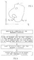
- the working area in which the robot must operate is enclosed by a boundary 1.
- the robot is an automated lawn mower, and the area A is a lawn.
- Islands 2 and 3 may be, e.g., trees and their vicinities or flower beds. Thus, we wish the mower to operate only in areas in which grass grows, and to avoid other areas.
- the robot can be coupled to a floor sweeper or a floor polisher or any other device which has to scan a flat surface.
- the boundaries 1, 2 and 3 may comprise a conducting wire.
- This type of boundary is shown in cross-section in Fig. 2, which shows a wire 4, comprising a metallic core 5 and a plastic outer layer 6.
- a current "i" is caused to flow through the wire, thus generating a magnetic field along the wire.
- the intensity of the current may be very low, since it is not necessary that the magnetic field be sensed at a great distance from the boundary, and it is sufficient that it be felt in the close vicinity of the wire.
- the magnetic field is sensed, according to this particular embodiment of the invention, by a magnetic field sensor provided on the lawn mower.
- the magnetic field and the sensor to sense it are conventional and well known in the art, and therefore are not described here in detail, for the sake of brevity.
- FIG. 3A shows a lawn mower L relative to the starting point "S" within the lawn, the lawn mower L being at a point ( ⁇ ,r) viz. at a distance r, which is measured by measuring the movement of the mower, and at an angle ⁇ from starting point S, which is measured by means of a compass.
- ⁇ ,r a point within the enclosed area S
- any point within the enclosed area S will have a unique polar coordinate.
- the lawn mower When it is desired to teach the robot the boundaries of its task, the lawn mower is caused first to move around the boundary 1 of Fig. 1.
- the memory means of the robot memorize the coordinates of the boundary 1, relative to starting point S.
- the boundary sensor positioned on the robot (not shown) senses the boundary 1.
- the boundaries 2 and 3 are sensed for the first time by the robot, and memorized for future use.
- the robot now has an initial map of the area, similar to what is shown in Fig. 3B, each point having been assigned a coordinate.
- the set of coordinates so created will be termed "the map" of the working area.
- the robot When it is desired to mow the lawn, the robot is brought to starting point S, and it is started according to a set of instructions which has been pre-programmed, and which may be different for each different task. For instance, a circular lawn may be better looking if mowed in circles, while a soccer field requires back-and-forth mowing.
- An automated lawn mower according to the invention may further be provided with a number of pre-set programs, from which the user can choose.
- the robot is further provided with distance-measuring means, such as an odometer or the like device.
- distance-measuring means such as an odometer or the like device.
- these devices are not fully accurate, and may provide only approximate distance values for any given position.
- the error in the measurement of the distance may derive from a variety of reasons, e.g., the slipping of wheels on a moist lawn, uneven ground, etc., and the error may build up to quite a substantial extent, impairing the ability of the robot to complete its task with a high degree of precision.
- precise measuring means exist, such as laser distance measurements, these are expensive and/or require calibration targets located in or around the working area. It is a purpose of the invention to avoid the use of such expensive and complicated distance-measuring means.
- the robot starting a task continuously compares the distance measured by the odometer or other distance measuring device, with the distance from an earlier position to the boundaries in the angular coordinate it is following. If the boundary is detected earlier than anticipated according to this comparison (or, in other words, if the difference between the distance according to the map and the measured distance is negative), the robot continues to move until the boundary is detected. If the difference between the distance according to the map and the measured distance is positive, or in other words, if the boundaries are encountered earlier than expected, actual value of the coordinate is corrected to be that of the map.
- the starting point will initially be the point "S”, and correction of distance errors will be effected relative to this point.
- the starting point may be updated to be another point within the area, e.g., a meeting point with the boundaries, for comparison purposes with the map of the area.
- the robot has been pre-programmed to avoid "islands", but will detect an island according to the actual position of the boundary detected, and will correct its present working map based on the detection of the boundary and the original map.
- the larger the number of bounded areas the higher the precision of the correction of the actual working map. Therefore, the islands actually help in keeping precision and correcting the actual working map. Therefore, if the working area is particularly large, it may be desirable to provide artificial islands for the purposes of map correction.
- Fig. 4 shows an alternative embodiment of the invention, in which the location of each point is measured in Cartesian coordinates.
- Cartesian coordinates As will be appreciated by the skilled person, it is not essential to the invention that any specific coordinates system be chosen, but it may be more convenient to select a particular set of coordinates, depending on the map correction process employed.
- Fig. 5A shows the correction of an error on one axis (Y in the example shown in the flow-sheet of Fig. 5A) is shown, according to one possible embodiment of the invention, while the error in the other axis is not dealt with.
- Fig. 5B shows a method according to another possible embodiment of the invention, in which both the X and the Y errors are corrected in one step. It should be noted that, although only the error on one axis can be corrected at a time in the embodiment of Fig. 5A, the error on the other axis can be corrected by moving in a direction perpendicular to the axis being corrected. The movement of the robot can be programmed such that both the X and Y location coordinates are updated at a suitable rate of correction.
- Fig. 5B another preferred embodiment of the invention is shown, in which the boundaries are marked with markers (4 in Fig. 5B), which have a unique identity.
- the markers will typically be conveniently evenly spaced, although any spacing scheme is possible.
- the markers can be of any suitable type, such as, and RF tag, magnetic tag or similar marker, which emits a signal identifiable by a sensor. In such a case, of course, a suitable sensor, capable of identifying unique identity signals must also be connected to the robot.
- the robot performs a complete loop around the edge and memorizes the shape of the boundary as well as the position of each marker (X,Y coordinates of each individual marker). This procedure allows for the correction of both the X and the Y coordinates error, each time an edge is detected, according to the method shown in the flow-sheet of Fig. 5B.
- Figs. 7, 8 and 9 illustrate a further embodiment of the robotic lawnmower of the present invention.
- the robot sweeps the space with overlapping straight lines by determining the location of the edge between uncut and cut grass.
- the lawnmower labeled 20 in Fig. 7, additionally includes a plurality of sensors 22, each one measuring the height of the grass in its general vicinity.
- Fig. 7 shows two areas, one 24 of cut grass and one 26 of uncut grass.
- sensors 22a and 22b will provide a high height output
- sensors 22c and 22d will provide a low height output.
- the control system of the lawnmower can determine generally where the edge between cut and uncut grass is.
- One embodiment of a sensor 22 is illustrated in Fig. 10 and described in detail hereinbelow.
- Fig. 8 details the operations performed by the control system of lawnmower 20 and Fig. 9 illustrates the movements of the lawnmower 20 at the edge of the lawn.
- the lawnmower 20 is cutting a swath 25 indicated by dotted arrows in Fig. 9, the sensors 22 continually measure the height of the lawn nearby (step 30).
- the control system with the navigation system (compass and odometer), steers the lawnmower 20 in the desired direction, as described hereinabove, while additionally ensuring that the edge of the lawn is maintained in a desired location vis-a-vis the sensors 22. For example, it may be desired to cut a swath which is only three-quarters the width of the lawnmower. For this situation, the edge between cut and uncut grass should be maintained between sensors 22a and 22b or between sensors 22c and 22d.
- the control system maintains the desired direction until the edge of the lawn is detected, as described hereinabove. At this point, the lawnmower 20 must change direction of movement while keeping the proper percentage of uncut grass under the lawnmower 20. It is noted that the lawnmower can move both forward and backward.
- Fig. 9 illustrates the change in direction.
- the lawnmower 20 moves in the forward direction along swath 25 (step 30).
- the lawnmower 20 performs an 'S' shaped backwards maneuver, labeled 40, using the navigation system, until the edge between cut and uncut lawn is sensed between the desired two sensors 22.
- This step is indicated in step 32 of Fig. 8 and produces an 'S' shaped cut in the lawn.
- line A in Fig. 9 the edge of the cut grass is maintained between the desired two sensors 22.
- step 34 the lawnmower 20 moves forward along the edge of the cut grass until the edge of the lawn is sensed once again. This movement is indicated by the short arrows 42 of Fig. 9. Finally, the lawnmower 20 backtracks along the new swath 44. Initially and until reaching the location of the line A, the lawnmower 20 utilizes only the compass information. Once the edge of cut grass is found again (at the location of line A), the control system utilizes both the compass and the sensor output to create the new swath 44. This is indicated at step 36 of Fig. 8.
- the lawnmower 20 has to return to locations of unfinished scanning, such as locations on the opposite side of a flower bed or tree. To do so, the lawnmower 20 utilizes the navigation system to head towards the desired location and, when it is close to the desired location, it additionally senses the edge between cut and uncut grass.
- Fig. 10 illustrates an exemplary lawn height sensor.
- the lawn sensor comprises a rotatable wing 50 connected to a potentiometer 52 via a pin 54 and a flexible joint 56.
- a weak spring 58 is attached around pin 54 and extensions 60 of spring 58 extend on either side of wing 50 and of a fixed pin 62.
- a cam 64 is connected also to pin 54 and a microswitch 66 measures the movement of cam 64.
- the rotation of the wing causes the cam 64 and flexible joint 56 to rotate, which rotation is measured by the potentiometer 52. Furthermore, if the wing 50 rotates too far, protrusions 68 of cam 64 will press against a rod 70 connected to microswitch 66 which will indicate maximum travel of wing 50.
- Figs. 11A and 11B illustrate two alternative embodiments of boundary markers and a sensor for detecting the boundary markers located on the lawnmower.
- Figs. 12A, 12B, 13A, 13B, 14A, 14B, 15 and 16 illustrate additional types of boundary markers.
- Figs. 11A and 11B illustrate the lawnmower 10 with a boundary sensor 80 attached thereto.
- the boundary is marked by a series of markers 82 placed into the ground on the edge of the lawn. Typically, the markers are placed at set distances one from the next. Alternatively, they can be placed close together along portions of the edge which are very curvy and further apart along straighter portions of the edge.
- the boundary is marked by a wire 84 which is marked in some suitable and detectable manner. The type of marking matches the type of sensor attached to the lawnmower 10.
- the boundary markers 82 have a magnet therein.
- the boundary marker 82 is formed of a plastic pin 90, a magnet 92 placed within pin 90 and a plastic cover 94 covering the magnet-pin unit.
- the boundary marker 82 is a metallic pin which is magnetized, as shown.
- the corresponding sensor 80 is a gauss meter, such as the model 4048 manufactured by F.W. Bell Inc. of the USA, or any other magnetometer which senses the magnetism in the combined unit.
- the distances between the boundary markers 82 are defined by the strength of the magnet 92 in such a way that at any point along the marked perimeter, at least two markers are detectable by the sensor on the robot.
- the senor 82 is a bar code reader, such as the model 1516 from Intermek Inc. of Seattle, Washington, USA.
- the corresponding boundary markers are, in Fig. 13A, a white cable 96 with black bar code markings 98 thereon.
- the bar code markings 98 are located at fixed distances from each other.
- the boundary markers are pins (typically of white plastic) with black markings 100 thereon.
- Figs. 14A and 14B illustrate a further embodiment which utilizes a Geiger counter, or other suitable radiometer, to detect the boundary markers.
- Fig. 14A illustrates a cable 102 having a piece of a radioactive mineral 104, such as Americium, located thereon and
- Fig. 14B illustrates an individual pin 106 (typically of plastic) having a radioactive mineral 104 thereon.
- a suitable Geiger counter for use with lawnmower 10 is the SURVIVOR 200, manufactured by Bicron Inc. of the USA.
- Fig. 15 illustrates a coil-capacitor circuit 110 incorporated into a plastic or ceramic substance 112. Such a circuit 110 is then placed into a pin unit such as pin 90 and cover 94 of Fig. 12A.
- the corresponding sensor 80 is a resonance tag reader such as the ones manufactured by Checkpoint Inc. of Thorofare, New Jersey, USA, for anti-theft protection in stores, such as clothing stores.
- the coil-capacitor unit 110 can be similar to those manufactured by Checkpoint or any other suitable coil-capacitor unit.
- Fig. 16 illustrates a further embodiment utilizing transceiver units 120.
- the transceiver unit 120 can be any suitable narrow band transmitting and receiving unit and is typically placed into a pin unit such as pin 90 and cover 94 of Fig. 12A.
- the corresponding sensor is a similar transceiver.
- Each transceiver, within each pin, operates at the same frequency and the sensor transceiver continually determines how close it is to the nearest transceiver unit 120. When the sensor transceiver comes to within a predetermined distance, the sensor transceiver determines that it has reached the boundary.
- the sensor 80 determines that the lawnmower 10 has reached the boundary when the signal sensor 80 receives is at or above a threshold level which is calculated as the expected reading five to ten inches from the marker or cable.
Abstract
Description
- The present invention relates to a method and related systems for navigation in an enclosed area. More particularly, the invention relates to method and apparatus which can be used to cause an automated device to move and to perform predetermined tasks within an enclosed area.
- The use of automated devices is widespread nowadays and used in countless applications. For instance, robots perform very precise and delicate tasks in medicine, aviation or in the construction of electronic devices. Mobile robots are also used for example, in automatic warehouses, where goods are retrieved and stored by means of computer-actuated robots. Other applications include fetching raw materials in the course of industrial manufacturing and removing and packaging finished pieces. In everyday life, attempts have also been made to exploit robots for lawn mowing and for vacuum cleaning.
- The major drawback of mobile robots, which the art has so far been unable to overcome, is the fact that their movements are limited to well predefined paths, normally requiring that they move along rails, or that they be provided with expensive navigation signs, positioned within the area in which they move, which operate as "stations" which redefine the exact position of the robot, and from which the program may direct the robot to the next station. These intermediate signs are expensive, take up space, and are inconvenient to use, since they must be very precisely positioned and cannot be easily moved.
- Another approach involves providing an area delimited by boundaries recognizable by the robot, and permitting the robot to effect a random walk therein, during which it carries out its tasks. This approach has severe drawbacks; firstly, when the robot moves within a predefined area by random walking, there is no way to ensure that the whole area will be covered by the operating tool. As a result, even though the robot may operate for a long period of time, unworked areas may be left at the end of the operation. Secondly, if the area to be worked is irregular, or comprises "islands", that is, areas which must not be worked, the random walk may lead to imperfect operation around such islands, as well as at those locations where the perimeter is of irregular shape. Thirdly, because the operation of the robot is not programmed to obtain a predetermined coverage, it is necessary to allow the random walk to go on for a long period of time, so as to increase the chances of covering a major portion of the area to be worked. This is not only energy consuming, but also leads to an increased wear of the equipment, and may also be environmentally undesirable due, for example, to noise or other pollution caused by the operation of the robot. Even if the robot is operated by sun energy, most of the aforesaid problems are not overcome, and additional problems exists, connected with such a mode of operation. For instance, the robot may not work properly in areas of the world where sun radiation is scarce or low, and may be inoperative for substantial parts of the day, due to cloudy weather, for example.
- A further approach involves preprogramming the robot with a blueprint of its designated area of operation, such as a floor map of a building in which a robot is to operate. This approach has two major drawbacks. Firstly, it requires preprogramming by the user, which makes in unpractical for extensive consumer use and secondly, it requires that such preprogramming is repeated each time something changes in the work area.
- It is therefore clear that it would be highly desirable to be able to provide means by which automated mechanisms may move and perform their task within a predetermined area, without being hindered by the need for predefined paths and rails, or by intermediate navigation signs or preprogramming, and which may carry out their task in a predetermined manner, without relying on random occurrences and/or on unstable energy sources.
- The present applicant has realized, that it is possible to free automated mechanisms, operating within an enclosed zone, from the need for preprogramming, from predefined paths and rails and from the need for intermediate navigation aids. An object of the present invention is to overcome the drawbacks of the prior art and to provide means by which a robot may perform its tasks within an enclosed area in a manner free from such limitations, with high precision and in a minimal period of time.
- It is an object of the present invention to provide a navigation method which fulfills the aforementioned goals.
- There is thus provided in accordance with a preferred embodiment of the invention a boundary detection system for an automated robot which is to operate within an enclosed area. The boundary detection system includes a magnetic sensor mounted on the automated robot, an outer boundary placed along the perimeter of the working area and an inner boundary placed along the perimeter of each area enclosed in the working area in which it is desired that the robot should not operate. The inner and outer boundaries are formed of passive magnetic means detectable by the magnetic sensor.
- Furthermore, in accordance with a preferred embodiment of the invention the passive magnetic means includes a plurality of pins having magnets therein.
- Furthermore, in accordance with a preferred embodiment of the invention the passive magnetic means includes a multiplicity of magnets each shaped into the form of pins.
- There is further provided, in accordance with a preferred embodiment of the invention, a boundary detection system for an automated robot which is to operate within an enclosed area. The boundary detection system includes a contrast pattern code reader mounted on the automated robot, an outer boundary placed along the perimeter of the working area and an inner boundary placed along the perimeter of each area enclosed in the working area in which it is desired that the robot should not operate. The inner and outer boundaries are formed of contrast means detectable by the contrast pattern code reader.
- Furthermore, in accordance with a preferred embodiment of the invention the boundary includes a two color guide wire having patterns of a first color at fixed distances thereon and a second color for the non-patterned portions of the guide wire.
- Furthermore, in accordance with a preferred embodiment of the invention the boundary includes a multiplicity of pins each having a contrast pattern thereon.
- Additionally, there is further provided, in accordance with a preferred embodiment of the invention, a boundary detection system for an automated robot which is to operate within an enclosed area. The boundary detection system includes a radiometer reader mounted on the automated robot, an outer boundary placed along the perimeter of the working area and an inner boundary placed along the perimeter of each area enclosed in the working area in which it is desired that the robot should not operate. The inner and outer boundaries are formed of radioactive means detectable by the radiometer.
- Furthermore, in accordance with a preferred embodiment of the invention the boundary includes a guide wire having a radioactive unit placed at fixed distances thereon.
- Furthermore, in accordance with a preferred embodiment of the invention the boundary includes a multiplicity of pins each having a radioactive unit thereon.
- Additionally, there is further provided, in accordance with a preferred embodiment of the invention, a boundary detection system for an automated robot which is to operate within an enclosed area. The boundary detection system includes a resonance tag meter mounted on the automated robot, an outer boundary placed along the perimeter of the working area and an inner boundary placed along the perimeter of each area enclosed in the working area in which it is desired that the robot should not operate. The inner and outer boundaries are formed of a multiplicity of pins having at least one coil-capacitive circuit therein.
- There is further provided, in accordance with a preferred embodiment of the invention, a boundary detection system for an automated robot which is to operate within an enclosed area. The boundary detection system includes a transceiver mounted on the automated robot, an outer boundary placed along the perimeter of the working area and an inner boundary placed along the perimeter of each area enclosed in the working area in which it is desired that the robot should not operate. The inner and outer boundaries are formed of a multiplicity of pins having at least one transceiver therein.
- Furthermore, in accordance with a preferred embodiment of the invention the robot is coupled to a selected one of the group of: a vacuum cleaner, a floor sweeper and a floor polisher.
- Additionally, there is provided, in accordance with a preferred embodiment of the invention, a method for automatically cutting a lawn. The method is characterized by including the steps of:
- A. providing a lawn mower with a robot and at least a plurality of lawn height sensors;
- B. cutting a first swath of lawn in a first direction;
- C. performing a maneuver, under control of the robot and in response to output of the lawn height sensors, in a second direction generally opposite of the first direction to bring the lawn mower to a location parallel to but overlapping the first swath by a predetermined percentage as indicated by the different output of the lawn height sensors;
- D. cutting a second swath of lawn parallel to the first swath while continually monitoring the lawn height output of the lawn height sensors thereby to ensure that the percentage of overlap is generally maintained;
- E. repeating the steps of performing a maneuver and cutting a second swath for further swaths of lawn, wherein the previously cut lawn is denoted by the first swath of lawn and the swath to be cut is denoted by the second swath of lawn.
- Furthermore, in accordance with a preferred embodiment of the invention the maneuver is an S shaped maneuver.
- Furthermore, in accordance with a preferred embodiment of the invention the step of providing includes the additional steps of:
- A. providing a boundary along the perimeter of the working area, the boundary being detectable by a proximity sensor;
- B. providing boundaries along the perimeter of each area enclosed in the working area, in which it is desired that the lawn mower should not operate, the boundaries also being detectable by a proximity sensor;
- C. providing a proximity sensor positioned on the lawn mower;
- D. providing processing means connected to the proximity sensor and receiving an input therefrom;
- E. providing location means on the lawn mower, to determine the coordinates of the robot relative to an arbitrary origin, at any specific time;
- F. providing direction finding means; and
- G. providing memory means to store values generated by the processing means and, optionally, by the location means.
- Furthermore, in accordance with a preferred embodiment of the invention the steps of cutting include the step of continuously determining the coordinates of the lawn mower by analyzing data obtained from the location means and by detecting the vicinity of a boundary.
- Additionally, there is provided, in accordance with a preferred embodiment of the invention, a grass height sensor which includes a housing, a rotatable wing against which grass can push, the wing having a pin attached thereto, a fixed second pin, connected to the housing, a spring attached around the pin, wherein the ends of the spring press against opposite sides of the wing and opposite sides of the fixed pin, and means for measuring the angle of rotation of the rotatable wing.
- Additionally, there is provided, in accordance with a preferred embodiment of the invention, an automated robot for operation within an enclosed area. the automated robot includes a proximity sensor positioned on the robot. The proximity sensor includes a sensor selected from the group of: a magnetic field detector, an acoustic detector, an electric field detector, a bar code reader, a radiometer, a resonance tag meter and a transceiver. The automated robot further includes processing means connected to the proximity sensor and receiving an input therefrom, location means, to determine the coordinates of the robot relative to an arbitrary origin, at any specific time, direction finding means and memory means to store values generated by the processing means and, optionally, by the location means.
- Furthermore, in accordance with a preferred embodiment of the invention the robot is coupled to a floor sweeper or a floor polisher.
- Additionally, there is provided, in accordance with a preferred embodiment of the invention, a system for automatically operating a robot within an enclosed area. The system includes a robot provided with a magnetic field detector and boundary means suitable for positioning along the perimeter of the working area. In each area enclosed in the working area in which it is desired that the robot does not operate, the boundary means are formed of passive magnetic means detectable by the magnetic field detector. The system further includes processing means on the robot, connected to the magnetic field detector and receiving an input therefrom.
- Furthermore, in accordance with a preferred embodiment of the invention the passive magnetic means includes a plurality of pins having magnets therein.
- Furthermore, in accordance with a preferred embodiment of the invention the passive magnetic means includes a multiplicity of magnets each shaped into the form of pins.
- Additionally, there is also provided, in accordance with a preferred embodiment of the invention, a system for automatically operating a robot within an enclosed area. The system includes a robot provided with a high contrast pattern code reader and boundary means suitable for positioning along the perimeter of the working area. In each area enclosed in the working area in which it is desired that the robot does not operate, the boundary means are formed of high contrast pattern means detectable by the high contrast pattern code reader. The system further includes processing means on the robot, connected to the code reader and receiving an input therefrom.
- Furthermore, in accordance with a preferred embodiment of the invention the boundary includes a two color guide wire having patterns of a first color at fixed distances thereon and a second color for the non-patterned portions of the guide wire.
- Furthermore, in accordance with a preferred embodiment of the invention the boundary includes a multiplicity of pins each having a high contrast pattern thereon.
- Additionally, there is provided, in accordance with a preferred embodiment of the invention, a system for automatically operating a robot within an enclosed area. The system includes a robot provided with a radiometer, boundary means suitable for positioning along the perimeter of the working area, and of each area enclosed in the working area in which it is desired the robot not to operate, the boundary means being formed of radioactive means detectable by the radiometer and processing means on the robot, connected to the radiometer and receiving an input therefrom.
- Furthermore, in accordance with a preferred embodiment of the invention, the boundary includes a guide wire having a radioactive unit placed at fixed distances thereon.
- There is thus provided in accordance with a preferred embodiment of the invention the boundary includes a multiplicity of pins each having a radioactive unit thereon.
- Additionally, there is provided, in accordance with a preferred embodiment of the invention, a system for automatically operating a robot within an enclosed area. The system includes a robot provided with a resonance tag meter, boundary means suitable for positioning along the perimeter of the working area and processing means on the robot, connected to the resonance tag meter and receiving an input therefrom. In each area enclosed in the working area in which it is desired the robot not to operate, the boundary means are formed of a multiplicity of pins having at least one coil-capacitive circuit therein the pins being detectable by the resonance tag meter.
- Additionally, there is provided, in accordance with a preferred embodiment of the invention, a system for automatically operating a robot within an enclosed area. the system includes a robot provided with a first transceiver, boundary means suitable for positioning along the perimeter of the working area and processing means on the robot, connected to the first transceiver and receiving an input therefrom. In each area enclosed in the working area in which it is desired the robot not to operate, the boundary means are formed of a multiplicity of pins having at least one transceiver therein, the pins being detectable by the first transceiver.
- Furthermore, in accordance with a preferred embodiment of the invention the system includes location means on the robot, to determine the coordinates of the robot relative to an arbitrary origin, at any specific time, memory means to store values generated by the processing means, direction finding means positioned on the robot, to determine the direction of travel thereof, and motion means, to cause the robot to move.
- Furthermore, in accordance with a preferred embodiment of the invention the robot is coupled to a device selected from the group of: a vacuum cleaner, a floor sweeper and a floor polisher.
- Additionally, in accordance with a preferred embodiment of the invention the system includes a plurality of lawn height sensors for measuring the height of the lawn and means for controlling the lawn mower to cut the lawn along an already cut swath of grass.
- The present invention will be understood and appreciated more fully from the following detailed description taken in conjunction with the drawings in which:
- Fig. 1 schematically shows an enclosed area within which a robot must operate, the shaded areas representing "islands" in which the robot must not enter;
- Fig. 2 shows, in cross-section, a boundary of Fig. 1, according to a particular embodiment of the invention;
- Figs. 3A and 3B illustrate the method of the invention, using polar coordinates;
- Fig. 4 illustrates the method of the invention, using Cartesian coordinates;
- Fig. 5A and 5B are flow-sheet illustrations of an example of a location correction process, according to one preferred embodiment of the invention;
- Fig. 6 is a flow chart of the operation of a system, according to one preferred embodiment of the invention;
- Fig. 7 is a pictorial illustration of a lawnmower following the line of cut grass, constructed and operative in accordance with a further preferred embodiment of the present invention;
- Fig. 8 is a flow chart illustration of a method of operating the lawnmower of Fig. 7;
- Fig. 9 is a pictorial illustration useful in understanding the method of Fig. 8;
- Fig. 10 is a schematic illustration of a lawn height sensor, useful in the method of Fig. 8;
- Figs. 11A and 11B are schematic illustrations of a lawnmower, a sensor and two types of boundary markings, forming further embodiments of the present invention; and
- Figs. 12A, 12B, 13A, 13B, 14A, 14B, 15 and 16 are schematic illustrations of various types of boundary markings useful in the embodiments of Figs. 11A and 11B.
- The present invention will be better understood through the following illustrative and non-limitative description of preferred embodiments.
- Looking now at Fig. 1, the working area in which the robot must operate, indicated at "A", is enclosed by a
boundary 1. Within the working area there are "islands" in which the robot must not penetrate, which are shadowed and enclosed byboundaries Islands - As stated, according to one particular embodiment of the invention, the
boundaries wire 4, comprising ametallic core 5 and a plasticouter layer 6. A current "i" is caused to flow through the wire, thus generating a magnetic field along the wire. The intensity of the current may be very low, since it is not necessary that the magnetic field be sensed at a great distance from the boundary, and it is sufficient that it be felt in the close vicinity of the wire. The magnetic field is sensed, according to this particular embodiment of the invention, by a magnetic field sensor provided on the lawn mower. The magnetic field and the sensor to sense it are conventional and well known in the art, and therefore are not described here in detail, for the sake of brevity. - Taking the lawn mower as an example, but it being understood that the invention is in no way limited to its use with a lawn mower, or with any other particular device, the invention operates as follows. A coordinates system is defined, as well as a starting point. Fig. 3A shows a lawn mower L relative to the starting point "S" within the lawn, the lawn mower L being at a point (θ,r) viz. at a distance r, which is measured by measuring the movement of the mower, and at an angle θ from starting point S, which is measured by means of a compass. Thus, as shown in Fig. 2B, any point within the enclosed area S will have a unique polar coordinate.
- When it is desired to teach the robot the boundaries of its task, the lawn mower is caused first to move around the
boundary 1 of Fig. 1. The memory means of the robot memorize the coordinates of theboundary 1, relative to starting point S. Throughout this teaching movement, the boundary sensor positioned on the robot (not shown) senses theboundary 1. Similarly, theboundaries - When it is desired to mow the lawn, the robot is brought to starting point S, and it is started according to a set of instructions which has been pre-programmed, and which may be different for each different task. For instance, a circular lawn may be better looking if mowed in circles, while a soccer field requires back-and-forth mowing. An automated lawn mower according to the invention may further be provided with a number of pre-set programs, from which the user can choose.
- The robot, as said, is further provided with distance-measuring means, such as an odometer or the like device. However, these devices are not fully accurate, and may provide only approximate distance values for any given position. The error in the measurement of the distance may derive from a variety of reasons, e.g., the slipping of wheels on a moist lawn, uneven ground, etc., and the error may build up to quite a substantial extent, impairing the ability of the robot to complete its task with a high degree of precision. While, of course, precise measuring means exist, such as laser distance measurements, these are expensive and/or require calibration targets located in or around the working area. It is a purpose of the invention to avoid the use of such expensive and complicated distance-measuring means.
- According to the invention, therefore, the robot starting a task continuously compares the distance measured by the odometer or other distance measuring device, with the distance from an earlier position to the boundaries in the angular coordinate it is following. If the boundary is detected earlier than anticipated according to this comparison (or, in other words, if the difference between the distance according to the map and the measured distance is negative), the robot continues to move until the boundary is detected. If the difference between the distance according to the map and the measured distance is positive, or in other words, if the boundaries are encountered earlier than expected, actual value of the coordinate is corrected to be that of the map.
- The starting point will initially be the point "S", and correction of distance errors will be effected relative to this point. As work proceeds, of course, the starting point may be updated to be another point within the area, e.g., a meeting point with the boundaries, for comparison purposes with the map of the area.
- Similarly, the robot has been pre-programmed to avoid "islands", but will detect an island according to the actual position of the boundary detected, and will correct its present working map based on the detection of the boundary and the original map. As will be understood by the skilled person, the larger the number of bounded areas, the higher the precision of the correction of the actual working map. Therefore, the islands actually help in keeping precision and correcting the actual working map. Therefore, if the working area is particularly large, it may be desirable to provide artificial islands for the purposes of map correction.
- As will be appreciated by the skilled person, operating according to the preferred embodiment of the invention described above is very convenient also in respect of the boundaries, since the wire or coil may be embedded in the soil, thus avoiding any actual or even aesthetic disturbance to the working area, and the power requirements to generate a localized magnetic field are very small.
- Fig. 4 shows an alternative embodiment of the invention, in which the location of each point is measured in Cartesian coordinates. As will be appreciated by the skilled person, it is not essential to the invention that any specific coordinates system be chosen, but it may be more convenient to select a particular set of coordinates, depending on the map correction process employed.
- One particular process, employing Cartesian coordinates, will be described hereinafter by way of example, with reference to the flow-sheets of Figs. 5A and 5B.
- In Fig. 5A the correction of an error on one axis (Y in the example shown in the flow-sheet of Fig. 5A) is shown, according to one possible embodiment of the invention, while the error in the other axis is not dealt with. Fig. 5B, on the other hand, shows a method according to another possible embodiment of the invention, in which both the X and the Y errors are corrected in one step. It should be noted that, although only the error on one axis can be corrected at a time in the embodiment of Fig. 5A, the error on the other axis can be corrected by moving in a direction perpendicular to the axis being corrected. The movement of the robot can be programmed such that both the X and Y location coordinates are updated at a suitable rate of correction.
- In Fig. 5B another preferred embodiment of the invention is shown, in which the boundaries are marked with markers (4 in Fig. 5B), which have a unique identity. The markers will typically be conveniently evenly spaced, although any spacing scheme is possible. The markers can be of any suitable type, such as, and RF tag, magnetic tag or similar marker, which emits a signal identifiable by a sensor. In such a case, of course, a suitable sensor, capable of identifying unique identity signals must also be connected to the robot.
- During the initiation process, the robot performs a complete loop around the edge and memorizes the shape of the boundary as well as the position of each marker (X,Y coordinates of each individual marker). This procedure allows for the correction of both the X and the Y coordinates error, each time an edge is detected, according to the method shown in the flow-sheet of Fig. 5B.
- Schematically speaking, the robot will operate according to the flow-sheet of Fig. 6.
- Reference is now made to Figs. 7, 8 and 9 which illustrate a further embodiment of the robotic lawnmower of the present invention. In this embodiment, the robot sweeps the space with overlapping straight lines by determining the location of the edge between uncut and cut grass.
- In the present embodiment, the lawnmower, labeled 20 in Fig. 7, additionally includes a plurality of
sensors 22, each one measuring the height of the grass in its general vicinity. Fig. 7 shows two areas, one 24 of cut grass and one 26 of uncut grass. Thus, sensors 22a and 22b will provide a high height output and sensors 22c and 22d will provide a low height output. - By comparing the height output of the
sensors 22, the control system of the lawnmower can determine generally where the edge between cut and uncut grass is. One embodiment of asensor 22 is illustrated in Fig. 10 and described in detail hereinbelow. - Fig. 8 details the operations performed by the control system of
lawnmower 20 and Fig. 9 illustrates the movements of thelawnmower 20 at the edge of the lawn. While thelawnmower 20 is cutting aswath 25 indicated by dotted arrows in Fig. 9, thesensors 22 continually measure the height of the lawn nearby (step 30). The control system, with the navigation system (compass and odometer), steers thelawnmower 20 in the desired direction, as described hereinabove, while additionally ensuring that the edge of the lawn is maintained in a desired location vis-a-vis thesensors 22. For example, it may be desired to cut a swath which is only three-quarters the width of the lawnmower. For this situation, the edge between cut and uncut grass should be maintained between sensors 22a and 22b or between sensors 22c and 22d. - The control system maintains the desired direction until the edge of the lawn is detected, as described hereinabove. At this point, the
lawnmower 20 must change direction of movement while keeping the proper percentage of uncut grass under thelawnmower 20. It is noted that the lawnmower can move both forward and backward. - Fig. 9 illustrates the change in direction. Initially, the
lawnmower 20 moves in the forward direction along swath 25 (step 30). Upon reaching the edge, thelawnmower 20 performs an 'S' shaped backwards maneuver, labeled 40, using the navigation system, until the edge between cut and uncut lawn is sensed between the desired twosensors 22. This step is indicated instep 32 of Fig. 8 and produces an 'S' shaped cut in the lawn. As shown by line A in Fig. 9, the edge of the cut grass is maintained between the desired twosensors 22. - In
step 34, thelawnmower 20 moves forward along the edge of the cut grass until the edge of the lawn is sensed once again. This movement is indicated by theshort arrows 42 of Fig. 9. Finally, thelawnmower 20 backtracks along thenew swath 44. Initially and until reaching the location of the line A, thelawnmower 20 utilizes only the compass information. Once the edge of cut grass is found again (at the location of line A), the control system utilizes both the compass and the sensor output to create thenew swath 44. This is indicated atstep 36 of Fig. 8. - As discussed with respect to the previous embodiments, the
lawnmower 20 has to return to locations of unfinished scanning, such as locations on the opposite side of a flower bed or tree. To do so, thelawnmower 20 utilizes the navigation system to head towards the desired location and, when it is close to the desired location, it additionally senses the edge between cut and uncut grass. - Reference is now made to Fig. 10 which illustrates an exemplary lawn height sensor. The lawn sensor comprises a
rotatable wing 50 connected to apotentiometer 52 via apin 54 and a flexible joint 56. Aweak spring 58 is attached aroundpin 54 andextensions 60 ofspring 58 extend on either side ofwing 50 and of a fixedpin 62. Acam 64 is connected also to pin 54 and amicroswitch 66 measures the movement ofcam 64. - The grass presses against the
wing 50, which, since it is not heavy, will rotate. In turn, thewing 50 pushes against the relevant one ofextensions 60. Since theother extension 60 is maintained in place by fixedpin 62, thespring 58 is tightened, thereby providing a returning force against the force of the grass. - The rotation of the wing causes the
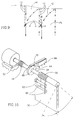
cam 64 and flexible joint 56 to rotate, which rotation is measured by thepotentiometer 52. Furthermore, if thewing 50 rotates too far,protrusions 68 ofcam 64 will press against arod 70 connected to microswitch 66 which will indicate maximum travel ofwing 50. - Reference is now made to Figs. 11A and 11B which illustrate two alternative embodiments of boundary markers and a sensor for detecting the boundary markers located on the lawnmower. Reference is also made to Figs. 12A, 12B, 13A, 13B, 14A, 14B, 15 and 16 which illustrate additional types of boundary markers.
- Figs. 11A and 11B illustrate the
lawnmower 10 with aboundary sensor 80 attached thereto. In Fig. 11A, the boundary is marked by a series ofmarkers 82 placed into the ground on the edge of the lawn. Typically, the markers are placed at set distances one from the next. Alternatively, they can be placed close together along portions of the edge which are very curvy and further apart along straighter portions of the edge. In Fig. 11B, the boundary is marked by awire 84 which is marked in some suitable and detectable manner. The type of marking matches the type of sensor attached to thelawnmower 10. - In one embodiment, shown in Figs. 12A and 12B, the
boundary markers 82 have a magnet therein. In the embodiment of Fig. 12A, theboundary marker 82 is formed of aplastic pin 90, amagnet 92 placed withinpin 90 and aplastic cover 94 covering the magnet-pin unit. In the embodiment of Fig. 12B, theboundary marker 82 is a metallic pin which is magnetized, as shown. - The corresponding
sensor 80, for both embodiments, is a gauss meter, such as the model 4048 manufactured by F.W. Bell Inc. of the USA, or any other magnetometer which senses the magnetism in the combined unit. The distances between theboundary markers 82 are defined by the strength of themagnet 92 in such a way that at any point along the marked perimeter, at least two markers are detectable by the sensor on the robot. - In a further embodiment, shown in Figs. 13A and 13B, the
sensor 82 is a bar code reader, such as the model 1516 from Intermek Inc. of Seattle, Washington, USA. The corresponding boundary markers are, in Fig. 13A, awhite cable 96 with blackbar code markings 98 thereon. Thebar code markings 98 are located at fixed distances from each other. In Fig. 13B, the boundary markers are pins (typically of white plastic) withblack markings 100 thereon. - Figs. 14A and 14B illustrate a further embodiment which utilizes a Geiger counter, or other suitable radiometer, to detect the boundary markers. Fig. 14A illustrates a
cable 102 having a piece of aradioactive mineral 104, such as Americium, located thereon and Fig. 14B illustrates an individual pin 106 (typically of plastic) having aradioactive mineral 104 thereon. A suitable Geiger counter for use withlawnmower 10 is the SURVIVOR 200, manufactured by Bicron Inc. of the USA. - Fig. 15 illustrates a coil-
capacitor circuit 110 incorporated into a plastic orceramic substance 112. Such acircuit 110 is then placed into a pin unit such aspin 90 and cover 94 of Fig. 12A. The correspondingsensor 80 is a resonance tag reader such as the ones manufactured by Checkpoint Inc. of Thorofare, New Jersey, USA, for anti-theft protection in stores, such as clothing stores. The coil-capacitor unit 110 can be similar to those manufactured by Checkpoint or any other suitable coil-capacitor unit. - Fig. 16 illustrates a further embodiment utilizing
transceiver units 120. Thetransceiver unit 120 can be any suitable narrow band transmitting and receiving unit and is typically placed into a pin unit such aspin 90 and cover 94 of Fig. 12A. The corresponding sensor is a similar transceiver. Each transceiver, within each pin, operates at the same frequency and the sensor transceiver continually determines how close it is to thenearest transceiver unit 120. When the sensor transceiver comes to within a predetermined distance, the sensor transceiver determines that it has reached the boundary. - For all of the above embodiments, the
sensor 80 determines that thelawnmower 10 has reached the boundary when thesignal sensor 80 receives is at or above a threshold level which is calculated as the expected reading five to ten inches from the marker or cable. - It will be appreciated that other types of markers and their corresponding detectors are incorporated within the present invention.
- All the above description and examples have been provided for the purpose of illustration, and are not intended to limit the invention in any way. Many modifications can be effected in the method and devices of the invention, without departing from its spirit.
Claims (13)
- A boundary detection system for an automated robot which is to operate within an enclosed area, the boundary detection system comprising:a. a magnetic sensor mounted on said automated robot;b. an outer boundary placed along the perimeter of the working area; andc. an inner boundary placed along the perimeter of each area enclosed in the working area in which it is desired that the robot should not operate,
wherein said inner and outer boundaries are formed of passive magnetic means detectable by said magnetic sensor. - A system according to claim 1, wherein said passive magnetic means comprises a plurality of pins having magnets therein.
- A system according to claim 1, wherein said passive magnetic means comprises a multiplicity of magnets each shaped into the form of pins.
- A boundary detection system for an automated robot which is to operate within an enclosed area, the boundary detection system comprising:a. a contrast pattern code reader mounted on said automated robot;b. an outer boundary placed along the perimeter of the working area; andc. an inner boundary placed along the perimeter of each area enclosed in the working area in which it is desired that the robot should not operate,
wherein said inner and outer boundaries are formed of contrast means detectable by said contrast pattern code reader. - A system according to claim 4, wherein the boundary comprises a two color guide wire having patterns of a first color at fixed distances thereon and a second color for the non-patterned portions of the guide wire.
- A system according to claim 4, wherein the boundary comprises a multiplicity of pins each having a contrast pattern thereon.
- A boundary detection system for an automated robot which is to operate within an enclosed area, the boundary detection system comprising:a. a radiometer reader mounted on said automated robot;b. an outer boundary placed along the perimeter of the working area; andc. an inner boundary placed along the perimeter of each area enclosed in the working area in which it is desired that the robot should not operate,
wherein said inner and outer boundaries are formed of radioactive means detectable by said radiometer. - A system according to claim 7, wherein the boundary comprises a guide wire having a radioactive unit placed at fixed distances thereon.
- A system according to claim 7, wherein the boundary comprises a multiplicity of pins each having a radioactive unit thereon.
- A boundary detection system for an automated robot which is to operate within an enclosed area, the boundary detection system comprising:a. a resonance tag meter mounted on said automated robot;b. an outer boundary placed along the perimeter of the working area; andc. an inner boundary placed along the perimeter of each area enclosed in the working area in which it is desired that the robot should not operate,
wherein said inner and outer boundaries are formed of a multiplicity of pins having at least one coil-capacitive circuit therein. - A boundary detection system for an automated robot which is to operate within an enclosed area, the boundary detection system comprising:a. a transceiver mounted on said automated robot;b. an outer boundary placed along the perimeter of the working area; andc. an inner boundary placed along the perimeter of each area enclosed in the working area in which it is desired that the robot should not operate,
wherein said inner and outer boundaries are formed of a multiplicity of pins having at least one transceiver therein. - A method for automatically cutting a lawn, the method characterized by comprising the steps of:a. providing a lawnmower with a robot and at least a plurality of lawn height sensors;b. cutting a first swath of lawn in a first direction;c. performing a maneuver, under control of said robot and in response to output of said lawn height sensors, in a second direction generally opposite of said first direction to bring said lawnmower to a location parallel to but overlapping said first swath by a predetermined percentage as indicated by the different output of said lawn height sensors;d. cutting a second swath of lawn parallel to said first swath while continually monitoring the lawn height output of said lawn height sensors thereby to ensure that the percentage of overlap is generally maintained;e. repeating said steps of performing a maneuver and cutting a second swath for further swaths of lawn, wherein the previously cut lawn is denoted by said first swath of lawn and the swath to be cut is denoted by said second swath of lawn.
- A grass height sensor comprising:a. a housing;b. a rotatable wing against which grass can push, said wing having a pin attached thereto;c. a fixed second pin, connected to said housing;d. a spring attached around said pin, wherein the ends of said spring press against opposite sides of said wing and opposite sides of said fixed pin; ande. means for measuring the angle of rotation of said rotatable wing.
Applications Claiming Priority (2)
| Application Number | Priority Date | Filing Date | Title |
|---|---|---|---|
| US08/554,691 US6255793B1 (en) | 1995-05-30 | 1995-11-07 | Navigation method and system for autonomous machines with markers defining the working area |
| US554691 | 1995-11-07 |
Publications (3)
| Publication Number | Publication Date |
|---|---|
| EP0774702A2 true EP0774702A2 (en) | 1997-05-21 |
| EP0774702A3 EP0774702A3 (en) | 1997-08-06 |
| EP0774702B1 EP0774702B1 (en) | 2001-10-10 |
Family
ID=24214334
Family Applications (1)
| Application Number | Title | Priority Date | Filing Date |
|---|---|---|---|
| EP96308037A Expired - Lifetime EP0774702B1 (en) | 1995-11-07 | 1996-11-06 | A boundary detection system for an automated robot |
Country Status (2)
| Country | Link |
|---|---|
| EP (1) | EP0774702B1 (en) |
| DE (1) | DE69615789T2 (en) |
Cited By (27)
| Publication number | Priority date | Publication date | Assignee | Title |
|---|---|---|---|---|
| WO1999015941A1 (en) * | 1997-09-19 | 1999-04-01 | Aktiebolaget Electrolux | Electronic bordering system |
| WO1999038056A1 (en) * | 1998-01-08 | 1999-07-29 | Aktiebolaget Electrolux | Electronic search system |
| WO2000025186A1 (en) * | 1998-10-23 | 2000-05-04 | Siemens Aktiengesellschaft | Self-contained anti-crash mobile system using limit markers |
| WO2000038029A1 (en) * | 1998-12-18 | 2000-06-29 | Dyson Limited | Autonomous vehicular appliance, especially vacuum cleaner |
| EP1078307A1 (en) * | 1998-05-11 | 2001-02-28 | Friendly Robotics Ltd. | Area coverage with an autonomous robot |
| WO2001042867A1 (en) * | 1999-12-06 | 2001-06-14 | Dyson Limited | Accessory for a cleaning device |
| WO2001056362A1 (en) | 2000-02-02 | 2001-08-09 | Logical Technologies Limited | An autonomous mobile apparatus for performing work within a predefined area |
| US6756219B1 (en) | 1998-12-09 | 2004-06-29 | Shionogi & Co., Ltd. | Human secretory type phospholipase a2 |
| WO2007109627A2 (en) * | 2006-03-17 | 2007-09-27 | Irobot Corporation | Lawn care robot |
| EP2244910A2 (en) * | 2008-02-21 | 2010-11-03 | Q Robotics, Llc | Adaptable container handling system |
| US8428776B2 (en) | 2009-06-18 | 2013-04-23 | Michael Todd Letsky | Method for establishing a desired area of confinement for an autonomous robot and autonomous robot implementing a control system for executing the same |
| WO2013071150A1 (en) * | 2011-11-11 | 2013-05-16 | Bar Code Specialties, Inc. (Dba Bcs Solutions) | Robotic inventory systems |
| EP2704882A2 (en) * | 2011-05-04 | 2014-03-12 | Harvest Automation, Inc. | Adaptable container handling robot with boundary sensing subsystem |
| US8937410B2 (en) | 2012-01-17 | 2015-01-20 | Harvest Automation, Inc. | Emergency stop method and system for autonomous mobile robots |
| US9147173B2 (en) | 2011-10-31 | 2015-09-29 | Harvest Automation, Inc. | Methods and systems for automated transportation of items between variable endpoints |
| US9826678B2 (en) | 2014-12-22 | 2017-11-28 | Irobot Corporation | Robotic mowing of separated lawn areas |
| US9854737B2 (en) | 2014-10-10 | 2018-01-02 | Irobot Corporation | Robotic lawn mowing boundary determination |
| CN107632597A (en) * | 2016-07-18 | 2018-01-26 | 苏州宝时得电动工具有限公司 | Intelligent work system |
| CN108228741A (en) * | 2016-12-15 | 2018-06-29 | 苏州宝时得电动工具有限公司 | Ground drawing generating method, device and the automatic working system of automatic working system |
| CN109032147A (en) * | 2018-09-10 | 2018-12-18 | 扬州方棱机械有限公司 | The method for generating grass-removing robot virtual boundary based on satellite positioning signal |
| US10274954B2 (en) | 2014-12-15 | 2019-04-30 | Irobot Corporation | Robot lawnmower mapping |
| US10426083B2 (en) | 2016-02-02 | 2019-10-01 | Irobot Corporation | Blade assembly for a grass cutting mobile robot |
| US10459063B2 (en) | 2016-02-16 | 2019-10-29 | Irobot Corporation | Ranging and angle of arrival antenna system for a mobile robot |
| US10785907B2 (en) | 2015-07-24 | 2020-09-29 | Irobot Corporation | Controlling robotic lawnmowers based on fluctuating weather conditions |
| US11115798B2 (en) | 2015-07-23 | 2021-09-07 | Irobot Corporation | Pairing a beacon with a mobile robot |
| CN113498665A (en) * | 2021-06-21 | 2021-10-15 | 深圳拓邦股份有限公司 | Lawn modeling method, lawn modeling apparatus, lawn mower, and computer-readable storage medium |
| US11470774B2 (en) | 2017-07-14 | 2022-10-18 | Irobot Corporation | Blade assembly for a grass cutting mobile robot |
Families Citing this family (2)
| Publication number | Priority date | Publication date | Assignee | Title |
|---|---|---|---|---|
| WO2015153109A1 (en) | 2014-03-31 | 2015-10-08 | Irobot Corporation | Autonomous mobile robot |
| US9510505B2 (en) | 2014-10-10 | 2016-12-06 | Irobot Corporation | Autonomous robot localization |
Citations (12)
| Publication number | Priority date | Publication date | Assignee | Title |
|---|---|---|---|---|
| US4133404A (en) * | 1975-04-25 | 1979-01-09 | Agile Systems, Inc. | Automatic lawn mower |
| GB2148490A (en) * | 1983-10-18 | 1985-05-30 | Atomic Energy Authority Uk | A survey vehicle for radioactive contamination |
| US4658928A (en) * | 1984-08-22 | 1987-04-21 | Samsung Co., Ltd. | Metal sensing apparatus for use in operable toys |
| DE3733939A1 (en) * | 1986-10-07 | 1988-04-14 | Murata Machinery Ltd | Detector device |
| FR2614428A1 (en) * | 1987-04-22 | 1988-10-28 | Fricot Claude | Transceiver hood |
| GB2204434A (en) * | 1987-01-02 | 1988-11-09 | C I Electronics Limited | Control system for a powered rail vehicle |
| DE3816622A1 (en) * | 1988-05-16 | 1989-11-30 | Ind Tech Res Inst | AUTOMATIC DRIVING VEHICLE, IN PARTICULAR WORKING VEHICLE LIKE LAWN MOWER OD. DGL. |
| DE3916730A1 (en) * | 1989-05-23 | 1989-12-07 | Goetting Hans Heinrich Jun | Arrangement for the track guidance of a vehicle over passive guiding means |
| WO1991009356A1 (en) * | 1989-12-07 | 1991-06-27 | Bergqvist Goeran L | A method and a system for navigation of unmanned vehicles |
| WO1992009941A1 (en) * | 1990-12-03 | 1992-06-11 | Eaton-Kenway, Inc. | Downward compatible agv system and methods |
| US5155775A (en) * | 1988-10-13 | 1992-10-13 | Brown C David | Structured illumination autonomous machine vision system |
| FR2696569A1 (en) * | 1992-10-07 | 1994-04-08 | Sn Eno | Device for limiting displacement of electric machine e.g lawn mower - uses double loop of perimeter wires to carry signals that are detected by machine as it approaches perimeter |
-
1996
- 1996-11-06 EP EP96308037A patent/EP0774702B1/en not_active Expired - Lifetime
- 1996-11-06 DE DE69615789T patent/DE69615789T2/en not_active Expired - Lifetime
Patent Citations (12)
| Publication number | Priority date | Publication date | Assignee | Title |
|---|---|---|---|---|
| US4133404A (en) * | 1975-04-25 | 1979-01-09 | Agile Systems, Inc. | Automatic lawn mower |
| GB2148490A (en) * | 1983-10-18 | 1985-05-30 | Atomic Energy Authority Uk | A survey vehicle for radioactive contamination |
| US4658928A (en) * | 1984-08-22 | 1987-04-21 | Samsung Co., Ltd. | Metal sensing apparatus for use in operable toys |
| DE3733939A1 (en) * | 1986-10-07 | 1988-04-14 | Murata Machinery Ltd | Detector device |
| GB2204434A (en) * | 1987-01-02 | 1988-11-09 | C I Electronics Limited | Control system for a powered rail vehicle |
| FR2614428A1 (en) * | 1987-04-22 | 1988-10-28 | Fricot Claude | Transceiver hood |
| DE3816622A1 (en) * | 1988-05-16 | 1989-11-30 | Ind Tech Res Inst | AUTOMATIC DRIVING VEHICLE, IN PARTICULAR WORKING VEHICLE LIKE LAWN MOWER OD. DGL. |
| US5155775A (en) * | 1988-10-13 | 1992-10-13 | Brown C David | Structured illumination autonomous machine vision system |
| DE3916730A1 (en) * | 1989-05-23 | 1989-12-07 | Goetting Hans Heinrich Jun | Arrangement for the track guidance of a vehicle over passive guiding means |
| WO1991009356A1 (en) * | 1989-12-07 | 1991-06-27 | Bergqvist Goeran L | A method and a system for navigation of unmanned vehicles |
| WO1992009941A1 (en) * | 1990-12-03 | 1992-06-11 | Eaton-Kenway, Inc. | Downward compatible agv system and methods |
| FR2696569A1 (en) * | 1992-10-07 | 1994-04-08 | Sn Eno | Device for limiting displacement of electric machine e.g lawn mower - uses double loop of perimeter wires to carry signals that are detected by machine as it approaches perimeter |
Cited By (48)
| Publication number | Priority date | Publication date | Assignee | Title |
|---|---|---|---|---|
| AU751789B2 (en) * | 1997-09-19 | 2002-08-29 | Husqvarna A.B. | Electronic bordering system |
| WO1999015941A1 (en) * | 1997-09-19 | 1999-04-01 | Aktiebolaget Electrolux | Electronic bordering system |
| WO1999038056A1 (en) * | 1998-01-08 | 1999-07-29 | Aktiebolaget Electrolux | Electronic search system |
| US6465982B1 (en) | 1998-01-08 | 2002-10-15 | Aktiebolaget Electrolux | Electronic search system |
| US7349759B2 (en) | 1998-05-11 | 2008-03-25 | F Robotics Acquisitions Ltd. | Area coverage with an autonomous robot |
| US6885912B2 (en) | 1998-05-11 | 2005-04-26 | F Robotics Acquistions Ltd. | Area coverage with an autonomous robot |
| EP1078307A4 (en) * | 1998-05-11 | 2001-07-18 | Friendly Robotics Ltd | Area coverage with an autonomous robot |
| EP1078307A1 (en) * | 1998-05-11 | 2001-02-28 | Friendly Robotics Ltd. | Area coverage with an autonomous robot |
| US7155309B2 (en) | 1998-05-11 | 2006-12-26 | F Robotics Ltd. | Area coverage with an autonomous robot |
| US6615108B1 (en) | 1998-05-11 | 2003-09-02 | F. Robotics Acquisitions Ltd. | Area coverage with an autonomous robot |
| WO2000025186A1 (en) * | 1998-10-23 | 2000-05-04 | Siemens Aktiengesellschaft | Self-contained anti-crash mobile system using limit markers |
| US6756219B1 (en) | 1998-12-09 | 2004-06-29 | Shionogi & Co., Ltd. | Human secretory type phospholipase a2 |
| WO2000038029A1 (en) * | 1998-12-18 | 2000-06-29 | Dyson Limited | Autonomous vehicular appliance, especially vacuum cleaner |
| WO2001042867A1 (en) * | 1999-12-06 | 2001-06-14 | Dyson Limited | Accessory for a cleaning device |
| WO2001056362A1 (en) | 2000-02-02 | 2001-08-09 | Logical Technologies Limited | An autonomous mobile apparatus for performing work within a predefined area |
| WO2007109627A2 (en) * | 2006-03-17 | 2007-09-27 | Irobot Corporation | Lawn care robot |
| WO2007109627A3 (en) * | 2006-03-17 | 2008-09-12 | Irobot Corp | Lawn care robot |
| US11194342B2 (en) | 2006-03-17 | 2021-12-07 | Irobot Corporation | Lawn care robot |
| US10037038B2 (en) | 2006-03-17 | 2018-07-31 | Irobot Corporation | Lawn care robot |
| US9713302B2 (en) | 2006-03-17 | 2017-07-25 | Irobot Corporation | Robot confinement |
| EP2244910B1 (en) * | 2008-02-21 | 2015-03-25 | Harvest Automation, Inc. | Adaptable container handling system |
| US8915692B2 (en) | 2008-02-21 | 2014-12-23 | Harvest Automation, Inc. | Adaptable container handling system |
| EP2244910A2 (en) * | 2008-02-21 | 2010-11-03 | Q Robotics, Llc | Adaptable container handling system |
| US8428776B2 (en) | 2009-06-18 | 2013-04-23 | Michael Todd Letsky | Method for establishing a desired area of confinement for an autonomous robot and autonomous robot implementing a control system for executing the same |
| EP2704882A2 (en) * | 2011-05-04 | 2014-03-12 | Harvest Automation, Inc. | Adaptable container handling robot with boundary sensing subsystem |
| EP2704882A4 (en) * | 2011-05-04 | 2014-10-15 | Harvest Automation Inc | Adaptable container handling robot with boundary sensing subsystem |
| US9147173B2 (en) | 2011-10-31 | 2015-09-29 | Harvest Automation, Inc. | Methods and systems for automated transportation of items between variable endpoints |
| US9568917B2 (en) | 2011-10-31 | 2017-02-14 | Harvest Automation, Inc. | Methods and systems for automated transportation of items between variable endpoints |
| WO2013071150A1 (en) * | 2011-11-11 | 2013-05-16 | Bar Code Specialties, Inc. (Dba Bcs Solutions) | Robotic inventory systems |
| US8937410B2 (en) | 2012-01-17 | 2015-01-20 | Harvest Automation, Inc. | Emergency stop method and system for autonomous mobile robots |
| US10750667B2 (en) | 2014-10-10 | 2020-08-25 | Irobot Corporation | Robotic lawn mowing boundary determination |
| US9854737B2 (en) | 2014-10-10 | 2018-01-02 | Irobot Corporation | Robotic lawn mowing boundary determination |
| US11452257B2 (en) | 2014-10-10 | 2022-09-27 | Irobot Corporation | Robotic lawn mowing boundary determination |
| US10274954B2 (en) | 2014-12-15 | 2019-04-30 | Irobot Corporation | Robot lawnmower mapping |
| US11231707B2 (en) | 2014-12-15 | 2022-01-25 | Irobot Corporation | Robot lawnmower mapping |
| US10874045B2 (en) | 2014-12-22 | 2020-12-29 | Irobot Corporation | Robotic mowing of separated lawn areas |
| US20190141888A1 (en) | 2014-12-22 | 2019-05-16 | Irobot Corporation | Robotic Mowing of Separated Lawn Areas |
| US10159180B2 (en) | 2014-12-22 | 2018-12-25 | Irobot Corporation | Robotic mowing of separated lawn areas |
| US9826678B2 (en) | 2014-12-22 | 2017-11-28 | Irobot Corporation | Robotic mowing of separated lawn areas |
| US11115798B2 (en) | 2015-07-23 | 2021-09-07 | Irobot Corporation | Pairing a beacon with a mobile robot |
| US10785907B2 (en) | 2015-07-24 | 2020-09-29 | Irobot Corporation | Controlling robotic lawnmowers based on fluctuating weather conditions |
| US10426083B2 (en) | 2016-02-02 | 2019-10-01 | Irobot Corporation | Blade assembly for a grass cutting mobile robot |
| US10459063B2 (en) | 2016-02-16 | 2019-10-29 | Irobot Corporation | Ranging and angle of arrival antenna system for a mobile robot |
| CN107632597A (en) * | 2016-07-18 | 2018-01-26 | 苏州宝时得电动工具有限公司 | Intelligent work system |
| CN108228741A (en) * | 2016-12-15 | 2018-06-29 | 苏州宝时得电动工具有限公司 | Ground drawing generating method, device and the automatic working system of automatic working system |
| US11470774B2 (en) | 2017-07-14 | 2022-10-18 | Irobot Corporation | Blade assembly for a grass cutting mobile robot |
| CN109032147A (en) * | 2018-09-10 | 2018-12-18 | 扬州方棱机械有限公司 | The method for generating grass-removing robot virtual boundary based on satellite positioning signal |
| CN113498665A (en) * | 2021-06-21 | 2021-10-15 | 深圳拓邦股份有限公司 | Lawn modeling method, lawn modeling apparatus, lawn mower, and computer-readable storage medium |
Also Published As
| Publication number | Publication date |
|---|---|
| EP0774702A3 (en) | 1997-08-06 |
| DE69615789D1 (en) | 2001-11-15 |
| EP0774702B1 (en) | 2001-10-10 |
| DE69615789T2 (en) | 2002-07-04 |
Similar Documents
| Publication | Publication Date | Title |
|---|---|---|
| US6255793B1 (en) | Navigation method and system for autonomous machines with markers defining the working area | |
| EP0774702B1 (en) | A boundary detection system for an automated robot | |
| US11845189B2 (en) | Domestic robotic system and method | |
| US10726568B2 (en) | Method and apparatus for map constructing and map correcting | |
| US7656291B2 (en) | System and method for determining proximity to a wireless boundary of programmable shape used in animal containment | |
| EP1149333B1 (en) | Autonomous vehicular appliance, especially vacuum cleaner | |
| US10656659B2 (en) | Method and apparatus for localization and mapping based on RFID | |
| CN105988471B (en) | Intelligent mowing system and mowing control method of mower | |
| EP2547192B1 (en) | Method and system for navigating a robotic garden tool | |
| US7349759B2 (en) | Area coverage with an autonomous robot | |
| CN106227212B (en) | The controllable indoor navigation system of precision and method based on grating map and dynamic calibration | |
| JP2017531423A (en) | Robotic mowing boundary line determination | |
| CN106659118A (en) | Autonomous robot localization | |
| JPWO2020041817A5 (en) | ||
| Lee et al. | Use of coded infrared light as artificial landmarks for mobile robot localization | |
| Udvardy et al. | Advanced navigation of automated vehicles in smart manufacturing | |
| Bae et al. | Use of coded infrared light for mobile robot localization | |
| Wang et al. | Neural networks-based terrain acquisition of unmarked area for robot mowers | |
| Jensfelt et al. | A mobile robot system for automatic floor marking | |
| Zu et al. | Localization for robot mowers covering unmarked operational area | |
| CN117475132A (en) | Boundary line identification method, intelligent device and readable storage medium | |
| CN115436922A (en) | Mobile object searching system | |
| Garratt | Wireless indoor mobile robot with RFID navigation map and live video: a thesis in the partial fulfilment of the requirements for the degree of Masters of Engineering in Mechatronics, Massey University, Palmerston North, New Zealand | |
| EP0636902A1 (en) | Method for determining the position of a mobile vehicle within a limited area and device embodying said method |
Legal Events
| Date | Code | Title | Description |
|---|---|---|---|
| PUAI | Public reference made under article 153(3) epc to a published international application that has entered the european phase |
Free format text: ORIGINAL CODE: 0009012 |
|
| AK | Designated contracting states |
Kind code of ref document: A2 Designated state(s): DE FR GB IT |
|
| PUAL | Search report despatched |
Free format text: ORIGINAL CODE: 0009013 |
|
| RHK1 | Main classification (correction) |
Ipc: G05B 1/03 |
|
| AK | Designated contracting states |
Kind code of ref document: A3 Designated state(s): DE FR GB IT |
|
| 17P | Request for examination filed |
Effective date: 19980202 |
|
| 17Q | First examination report despatched |
Effective date: 19990727 |
|
| GRAG | Despatch of communication of intention to grant |
Free format text: ORIGINAL CODE: EPIDOS AGRA |
|
| RAP1 | Party data changed (applicant data changed or rights of an application transferred) |
Owner name: FRIENDLY ROBOTICS LTD. |
|
| GRAG | Despatch of communication of intention to grant |
Free format text: ORIGINAL CODE: EPIDOS AGRA |
|
| GRAG | Despatch of communication of intention to grant |
Free format text: ORIGINAL CODE: EPIDOS AGRA |
|
| GRAH | Despatch of communication of intention to grant a patent |
Free format text: ORIGINAL CODE: EPIDOS IGRA |
|
| GRAH | Despatch of communication of intention to grant a patent |
Free format text: ORIGINAL CODE: EPIDOS IGRA |
|
| GRAA | (expected) grant |
Free format text: ORIGINAL CODE: 0009210 |
|
| AK | Designated contracting states |
Kind code of ref document: B1 Designated state(s): DE FR GB IT |
|
| PG25 | Lapsed in a contracting state [announced via postgrant information from national office to epo] |
Ref country code: IT Free format text: LAPSE BECAUSE OF FAILURE TO SUBMIT A TRANSLATION OF THE DESCRIPTION OR TO PAY THE FEE WITHIN THE PRE;WARNING: LAPSES OF ITALIAN PATENTS WITH EFFECTIVE DATE BEFORE 2007 MAY HAVE OCCURRED AT ANY TIME BEFORE 2007. THE CORRECT EFFECTIVE DATE MAY BE DIFFERENT FROM THE ONE RECORDED.SCRIBED TIME-LIMIT Effective date: 20011010 |
|
| REF | Corresponds to: |
Ref document number: 69615789 Country of ref document: DE Date of ref document: 20011115 |
|
| REG | Reference to a national code |
Ref country code: GB Ref legal event code: IF02 |
|
| ET | Fr: translation filed | ||
| PLBE | No opposition filed within time limit |
Free format text: ORIGINAL CODE: 0009261 |
|
| STAA | Information on the status of an ep patent application or granted ep patent |
Free format text: STATUS: NO OPPOSITION FILED WITHIN TIME LIMIT |
|
| 26N | No opposition filed | ||
| REG | Reference to a national code |
Ref country code: FR Ref legal event code: PLFP Year of fee payment: 20 |
|
| PGFP | Annual fee paid to national office [announced via postgrant information from national office to epo] |
Ref country code: GB Payment date: 20151127 Year of fee payment: 20 |
|
| PGFP | Annual fee paid to national office [announced via postgrant information from national office to epo] |
Ref country code: FR Payment date: 20151116 Year of fee payment: 20 |
|
| PGFP | Annual fee paid to national office [announced via postgrant information from national office to epo] |
Ref country code: DE Payment date: 20151229 Year of fee payment: 20 |
|
| REG | Reference to a national code |
Ref country code: DE Ref legal event code: R071 Ref document number: 69615789 Country of ref document: DE |
|
| REG | Reference to a national code |
Ref country code: GB Ref legal event code: PE20 Expiry date: 20161105 |
|
| PG25 | Lapsed in a contracting state [announced via postgrant information from national office to epo] |
Ref country code: GB Free format text: LAPSE BECAUSE OF EXPIRATION OF PROTECTION Effective date: 20161105 |