EP0779079A1 - Single electrode lead for double-chamber cardiac stimulators, especially for DD cardiac stimulators - Google Patents
Single electrode lead for double-chamber cardiac stimulators, especially for DD cardiac stimulators Download PDFInfo
- Publication number
- EP0779079A1 EP0779079A1 EP96118563A EP96118563A EP0779079A1 EP 0779079 A1 EP0779079 A1 EP 0779079A1 EP 96118563 A EP96118563 A EP 96118563A EP 96118563 A EP96118563 A EP 96118563A EP 0779079 A1 EP0779079 A1 EP 0779079A1
- Authority
- EP
- European Patent Office
- Prior art keywords
- probe
- electrode
- single electrode
- preform element
- atrial
- Prior art date
- Legal status (The legal status is an assumption and is not a legal conclusion. Google has not performed a legal analysis and makes no representation as to the accuracy of the status listed.)
- Granted
Links
Images

Classifications
-
- A—HUMAN NECESSITIES
- A61—MEDICAL OR VETERINARY SCIENCE; HYGIENE
- A61N—ELECTROTHERAPY; MAGNETOTHERAPY; RADIATION THERAPY; ULTRASOUND THERAPY
- A61N1/00—Electrotherapy; Circuits therefor
- A61N1/02—Details
- A61N1/04—Electrodes
- A61N1/05—Electrodes for implantation or insertion into the body, e.g. heart electrode
- A61N1/056—Transvascular endocardial electrode systems
Definitions
- At least one atrial electrode of the probe is in contact with the inner wall of the heart and thus a good contact is established for the detection of own actions of the heart and an atrial stimulation.
- the atrial electrode in the area of the cardiac septum - i.e. e.g. on the left wall of the right atrium - can be positioned.
- the electrode is thus as far as possible from the phrenic nerve, which runs past the right outside of the heart, so that an undesirable side effect of stimulation of the phrenic nerve, which is located in the immediate vicinity of the right wall of the atrium, is caused thereby , uncontrolled diaphragmatic stimulation can be prevented.
- the atrial ring electrode 11 is placed on the sleeve part 19 and, as is not shown, is provided with an electrical lead.
- an electrical lead 15 is shown in the form of a coiled wire that leads to the ventricular electrode 9 at the electrode tip 8.
- the cuff part 19 is also shown in its straight shape due to the guide wire 16 inserted into the lumen 23.
Abstract
Description
Die vorliegende Erfindung betrifft eine Einzel-Elektrodensonde - also eine sogenannte "Single Lead" - für Zweikammer-Herzschrittmachersysteme, insbesondere für DDD-Herzschrittmachersysteme, zum Einführen in das Herz mit den im Oberbegriff des Anspruches 1 angegebenen Merkmalen. In diesem Zusammenhang ist anzumerken, daß das eigentliche Schrittmachergerät einerseits und die Elektrodensonde andererseits eines Herzschrittmachersystems prinzipiell als getrennte Komponenten aufgefaßt werden. Um hier größtmögliche Kombinationsvielfalt zu gewährleisten, werden üblicherweise genormte Steckverbindungen zur elektrischen und mechanischen Verbindung zwischen Schrittmachergerät einerseits und Elektrodensonde andererseits verwendet. Ferner ist darauf hinzuweisen, daß solche Elektrodensonden auch für Defibrillatoren zum Einsatz kommen können.The present invention relates to a single electrode probe - a so-called "single lead" - for two-chamber pacemaker systems, in particular for DDD pacemaker systems, for insertion into the heart with the features specified in the preamble of claim 1. In this context it should be noted that the actual pacemaker device on the one hand and the electrode probe on the other hand of a pacemaker system are in principle understood as separate components. In order to ensure the greatest possible variety of combinations here, standardized plug connections are usually used for the electrical and mechanical connection between the pacemaker device on the one hand and the electrode probe on the other. It should also be noted that such electrode probes can also be used for defibrillators.
Zu der dieser Erfindung zugrundeliegenden Problematik ist auszuführen, daß neuere Erkenntnisse der Herzschrittmachertechnik bei einschlägigen pathologischen Befunden die Anwendung von sogenannten DDD-Herzschrittmachersystemen empfehlen. Diese Spezifikation "DDD" (= Dual pacing/Dual sensing/Demand + Triggered) bedeutet, daß einerseits eine Stimulation ("Pacing") in beiden Herzkammern vorgenommen wird und daß andererseits noch vorhandene Eigenaktionen des Sinus- bzw. AV-Knotens des Herzens sowohl im Atrium, als auch im Ventrikel erfaßt werden ("Sensing"). Zu diesem Zweck sind bereits sogenannte "Double-Lead"-DDD-Schrittmachersysteme bekannt. Deren Hauptnachteil ist es jedoch, daß zwei getrennte Elektrodensonden in das Herz implantiert und dort positioniert werden müssen, nämlich eine üblicherweise in J-Form ausgebildete Elektrode im Atrium und eine weitere Elektrode im Ventrikel des Herzens. Die atriale J-Elektrode bringt einen hohen Implantationsaufwand mit sich, der von vielen Ärzten gescheut wird. Außerdem spricht eine erhöhte Gefahr von Thrombosen und infolgedessen von Embolien aufgrund der Thrombogenität der Elektrodensondenmaterialien gegen die Implantation einer Vielzahl von Elektrodensonden.Regarding the problem on which this invention is based, it must be stated that recent findings in pacemaker technology recommend the use of so-called DDD pacemaker systems in the case of relevant pathological findings. This specification "DDD" (= D ual pacing / D ual sensing / D emand + Triggered) means that on the one hand a pacing ( "Pacing") is carried out in two chambers of the heart and on the other hand remaining intrinsic actions of the sine or AV node of the heart both in the atrium and in the ventricle ("sensing"). For this purpose, so-called "double lead" DDD pacemaker systems are already known. The main disadvantage, however, is that two separate electrode probes have to be implanted in the heart and positioned there, namely an electrode which is usually in the form of a J in the atrium and another electrode in the ventricle of the heart. The atrial J electrode entails a high level of implantation work, which many doctors shy away from. In addition, an increased risk of thrombosis and, as a result, of embolism due to the thrombogenicity of the electrode probe materials speaks against the implantation of a large number of electrode probes.
Einen aus Praxisgründen bisher akzeptierten Kompromiß stellen VDD-(= Ventricular pacing/Dual sensing/Demand + Triggered-) Herzschrittmachersysteme mit einer Einzel-Elektrodensonde dar. Deren Konstruktion umfaßt eine Einzelsonde, bei der eine ventrikuläre Elektrode an der Sondenspitze und zwei atriale Ringelektroden in entsprechender Entfernung von der Ventrikel-Elektrode am Sondenkörper angeordnet sind. Die atrialen Ringelektroden werden dazu verwendet, das atriale Potential zu erfassen, wodurch die ventrikuläre Stimulation nach einer geeigneten atrioventrikulären Verzögerung getriggert wird. Die ventrikuläre Stimulation kann bipolar erfolgen. Diese Art von Schrittmachersystem arbeitet zufriedenstellend bei Patienten mit stabiler Vorhofaktivität, guten atrialen Wahrnehmungseigenschaften und normaler Sinusknotenfunktion.One from practical reasons previously accepted compromise provide VDD - (= V entricular pacing / D ual sensing / D emand + triggered-) pacemaker systems with a single electrode probe is the construction comprises a single probe in which a ventricular electrode at the probe tip and two atrial. Ring electrodes are arranged at a corresponding distance from the ventricle electrode on the probe body. The atrial ring electrodes are used to sense the atrial potential, thereby triggering ventricular pacing after an appropriate atrioventricular delay. Ventricular pacing can be bipolar. This type of pacemaker system works satisfactorily in patients with stable atrial activity, good atrial sensing properties and normal sinus node function.
Grundsätzlich ist es zwar denkbar, die vorstehend erörterten Einzel-Elektrodensonden auch für DDD-Herzschrittmachersysteme einzusetzen. Jedoch stellt hier ein Problem dar, daß die atrialen Ringelektroden nicht wandständig plaziert, sondern frei im Blutstrom schwimmen. Diese sogenannten "flottierenden" Elektroden im Atrium führen zu erheblichen Einschränkungen der Stimulationseigenschaften, da meist sehr hohe Stimulationsamplituden benutzt werden müssen. Der Hauptgrund hierfür ist die fehlende Wandständigkeit der flottierenden Elektroden. Die hohen Stimulationsamplituden bringen den Nachteil eines hohen Energieverbrauches und häufiger Phrenikus-Stimulation mit sich, weswegen solche Einzel-Elektroden üblicherweise nur bei VDD-Herzschrittmachersystemen eingesetzt werden.In principle, it is conceivable to use the single-electrode probes discussed above also for DDD pacemaker systems. However, a problem here is that the atrial ring electrodes are not placed on the wall, but floating freely in the bloodstream. These so-called "floating" electrodes in the atrium lead to considerable restrictions in the stimulation properties, since usually very high stimulation amplitudes have to be used. The main reason for this is the lack of wall integrity of the floating electrodes. The high stimulation amplitudes have the disadvantage of high energy consumption and frequent phrenic stimulation, which is why such single electrodes are usually only used in VDD pacemaker systems.
Ein weiterer Ansatz für eine Einzel-Elektrodensonde zur Verwendung in einem DDD-Herzschrittmachersystem ist aus dem Artikel von J. Hirschberg et al "New Dual Chamber Single Lead System" aus der Fachzeitschrift "PACE", November 1994, S. 1870 bis 1872 bekannt. Bei dieser Sonde handelt es sich um eine modifizierte bipolare Standard-Elektrode, deren Kopf im Atrium aktiv befestigt wird. Die ventrikuläre Elektrode ist als Ringelektrode ausgeführt. Zur Implantation wird nun die atriale Spitze mittels eines üblichen Führungsdrahtes - ein sogenannter "Mandrin" - an der Innenseite der rechten Außenwand des Vorhofes befestigt. Anschließend wird der Führungsdraht einige Zentimeter zurückgezogen und die Sonde mit ihrem Mittenbereich in das rechte Ventrikel vorgeschoben. Durch nochmaliges Einführen des Führungsdrahtes in die Sonde wird die dabei gebildete Sondenschlaufe, die die Ringelektrode trägt, in optimalem Kontakt mit der rechten Ventrikelwand gebracht. Anschließend wird der Führungsdraht herausgezogen, wobei eine ausreichende Sondenlänge innerhalb des rechten Ventrikels verbleibt, um eine Schlaufe innerhalb des Ventrikels zu bilden. Dabei tritt die Sonde zweimal durch die Tricuspidal-Klappe des Herzens hindurch.Another approach for a single electrode probe for use in a DDD pacemaker system is known from the article by J. Hirschberg et al "New Dual Chamber Single Lead System" from the journal "PACE", November 1994, pp. 1870 to 1872. This probe is a modified standard bipolar electrode, the head of which is actively attached in the atrium. The ventricular electrode is designed as a ring electrode. For implantation, the atrial tip is now attached to the inside of the right outer wall of the atrium using a conventional guide wire - a so-called "stylet". The guidewire is then withdrawn a few centimeters and the center of the probe is pushed into the right ventricle. By reinserting the guide wire into the probe, the probe loop that is formed and carries the ring electrode is brought into optimal contact with the right ventricular wall. The guidewire is then withdrawn, leaving a sufficient length of probe within the right ventricle to form a loop within the ventricle. The probe passes through the tricuspid valve of the heart twice.
Problematisch bei dieser vorbekannten Einzel-Elektrodensonde ist einerseits die Tatsache, daß die Elektrodenspitze im Atrium aktiv verankert werden muß, damit überhaupt das nachfolgende Einführen der Sonde in das Ventrikel in Form einer Schlaufe vonstatten gehen kann. Auch die Schlaufenbildung selbst stellt einen diffizilen Implantationsschritt dar. Die zweimalige Durchführung der Sonde durch die Tricuspidalis-Klappe kann deren Funktionsfähigkeit beeinträchtigen. So kann ein hoher Rückstrom des Blutes vom Ventrikel in das Atrium bei der Kontraktion des Ventrikels beobachtet werden. Zudem können durch die doppelt durchgeführte Elektrodensonde die Tricuspidalklappen geschädigt werden.The problem with this previously known single-electrode probe is on the one hand the fact that the electrode tip must be actively anchored in the atrium so that the subsequent insertion of the probe into the ventricle can take place in the form of a loop. Loop formation itself is also a difficult implantation step. Passing the probe through the tricuspidal valve twice can impair its functionality. A high reverse flow of blood from the ventricle into the atrium can be observed when the ventricle contracts. In addition, the tricuspid valves can be damaged by the double electrode probe.
Ausgehend von der geschilderten Problematik liegt der Erfindung die Aufgabe zugrunde, eine Einzel-Elektrodensonde insbesondere für DDD-Herzschrittmachersysteme zu schaffen, die gegenüber herkömmlichen Sonden einen geringeren Aufwand beim Implantieren und Positionieren hervorruft, andererseits aber eine stark verbesserte und insbesondere sowohl im Atrium als auch Ventrikel wandständige Positionierung der atrialen und ventrikulären Elektroden erlaubt. Zusätzlich sollen Beeinträchtigungen durch eine Mehrzahl von Sondenkörpern sowohl im Blutgefäß als auch innerhalb des Herzens - z.B. die zweimalige Sondendurchführung durch die Tricuspidalklappe - vermieden werden.Based on the problems described, the object of the invention is to create a single electrode probe, in particular for DDD pacemaker systems, which causes less effort in implantation and positioning compared to conventional probes, but on the other hand a greatly improved and in particular both in the atrium and the ventricle Wall-mounted positioning of the atrial and ventricular electrodes allowed. In addition, impairments caused by a plurality of probe bodies are said to occur both in the blood vessel and within the heart - e.g. the double probe through the tricuspid valve - be avoided.
Die Lösung dieser Aufgabe ist im Kennzeichnungsteil des Anspruches 1 angegeben. Die demgemäß vorgesehene Erfindung beruht dabei auf der Grundidee, der Sonde auf ihrer im implantierten Zustand im Vorhof plazierten Teillänge eine solche Form zu geben, daß mindestens eine atriale Elektrode - üblicherweise eine Ringelelektrode - der Sonde an der Vorhofwand des Herzens wandständig anlegbar ist. Um dies zu erreichen, ist die Sonde auf der genannten Teillänge mit einem elastischen Vorformelement versehen, das der Sonde dort eine definiert ausgelenkte Form gibt. Aufgrund seiner Elastizität kann das Vorformelement jedoch aus seiner definierten Gestalt in einen im wesentlichen geradlinigen gestreckten Zustand übergeführt werden, was mit Hilfe des üblichen, bei der Sondenimplantation verwendeten Führungsdrahtes erfolgt. Der Führungsdraht muß dabei in seinen Elastizitätseigenschaften natürlich signifikant steifer sein als das Vorformelement.The solution to this problem is specified in the characterizing part of claim 1. The invention thus provided is based on the basic idea of giving the probe such a shape on its part length placed in the atrium in the implanted state that at least one atrial electrode - usually a striped electrode - of the probe can be placed on the wall of the atrium of the heart. To achieve this is the Provide the probe with an elastic preform element along the partial length mentioned, which gives the probe a defined deflected shape there. Due to its elasticity, however, the preform element can be converted from its defined shape into an essentially straight, stretched state, which is done with the help of the usual guide wire used in probe implantation. The elasticity of the guide wire must of course be significantly stiffer than that of the preform element.
Beim Implantationsvorgang wird vor der eigentlichen Implantation der Sonde der Führungsdraht bis zum Anschlag an der Sondenspitze vorgeschoben, wobei durch diesen Vorschub des Führungsdrahtes eine Zugkraft auf den Sondenkörper ausgeübt wird, die zu einer Streckung der Sonde im Bereich des Vorformelements führt. In diesem gestreckten Zustand kann dann die Sonde in das Herz eingeführt werden.During the implantation process, before the actual implantation of the probe, the guide wire is pushed as far as it will go against the tip of the probe, this feed of the guide wire exerting a tensile force on the probe body, which leads to a stretching of the probe in the region of the preform element. In this stretched condition, the probe can then be inserted into the heart.
Nach der Implantierung der Sonde und dem Herausziehen des Führungsdrahtes wird die Sonde dann auf der besagten Teillänge durch das Vorformelement so ausgelenkt, daß die Sonde mit mindestens einer atrialen Ring-Elektrode an der Vorhofwand des Herzens anliegt.After the implantation of the probe and the pulling out of the guidewire, the probe is then deflected along the said partial length by the preform element such that the probe rests on the atrial wall of the heart with at least one atrial ring electrode.
Da ferner in üblicher Weise die ventrikuläre Elektrode im Bereich der Herzkammer an der Herzkammerwand anliegt, kann eine DDD-Stimulation mit sowohl atrial als auch ventrikulär anliegenden Elektroden mit allen dadurch erzielbaren Vorteilen, wie guten Sensing-Eigenschaften und optimaler Reizschwelle für die Stimulation erfolgen.Furthermore, since the ventricular electrode is in contact with the ventricular wall in the area of the ventricle in the usual way, DDD stimulation with both atrial and ventricular electrodes can be achieved with all the advantages that can be achieved, such as good sensing properties and optimal stimulation threshold for the stimulation.
In den Ansprüchen 2 und 3 sind vorteilhafte Gestaltungen für das Vorformelement angegeben. Mit diesen Gestaltungen kann erreicht werden, daß mindestens eine atriale Elektrode der Sonde wandständig an der Herzinnenwand anliegt und damit ein guter Kontakt für die Erfassung von Eigenaktionen des Herzens und eine atriale Stimulation hergestellt wird. Insbesondere kann erreicht werden, daß die atriale Elektrode im Bereich der Herzscheidewand - also z.B. an der linken Wand des rechten Vorhofes - positionierbar ist. Die Elektrode liegt damit so weit wie möglich vom Phrenikus-Nerv, der an der rechten Herzaußenseite vorbeiläuft, entfernt, so daß eine als unerwünschter Nebeneffekt auftretende Stimulation des Phrenikus-Nerves, der sich in unmittelbarer Nähe der rechten Wand des Atriums befindet, mit davon hervorgerufenen, unkontrollierten Zwerchfellstimulationen unterbunden werden kann.In the
Durch die im Anspruch 2 angegebene helixförmige Gestalt des Vorformelements wird eine gute Lagesicherung der Sonde im Vorhof erreicht. Die im Anspruch 3 angegebene omegaförmige Gestalt des Vorformelements ist in diesem Zusammenhang zwar weniger wirksam, jedoch ist der herstellungstechnische Aufwand für dieses Vorformelement geringer. Welcher Variante hier der Vorzug zu geben ist, wird sich nach individuellen Voraussetzungen beim jeweiligen Patienten richten.Due to the helical shape of the preform element specified in
Das nach Anspruch 4 vorgesehene weitere Vorformelement auf einer im Ventrikel zu plazierenden Teillänge der Sonde führt dazu, daß nach dem Entfernen des Führungsdrahtes der Elektrodenkopf z.B. eine an sich bekannte J-Form annimmt. Die Elektrode an der Sondenspitze kann damit in der Nähe des AV-Knotens des Herzens positioniert werden, was hinsichtlich einer möglichst optimalen Nachahmung der natürlichen Stimulationsprozesse der Herzmuskulatur vorteilhaft ist. Die vom Herzschrittmacher erzeugten Reize laufen dabei nämlich - analog dem natürlichen Vorgang - ausgehend vom AV-Knoten das Septum hin ab und von dort in die außenseitigen Herzwände.The further preform element provided according to
Ferner ist bei dieser Ausführungsform von Vorteil, daß einerseits beim Implantieren der Sonde diese sich komplett in einem relativ geradlinig gestreckten Zustand befindet, was das Implantieren wesentlich erleichtert.It is also advantageous in this embodiment that, on the one hand, when the probe is implanted, the probe is completely in a relatively straight-line state, which considerably facilitates the implantation.
Beim allmählichen Herausziehen des Führungsdrahtes nach dem Positionieren der Sonde nimmt erst der Elektrodenkopf seine J-Form an, d.h., daß die Elektrodenspitze in eine Richtung weist, die der Auszugsrichtung der Sonde entgegengesetzt gerichtet ist. Dies führt zu einer guten Festlegung der Elektrode an der Sondenspitze im Bereich des AV-Knotens. Diese Festlegung unterstützt ferner die optimale Positionierung der Sonde. Beim weiteren Herausziehen des Führungsdrahtes und der Auslenkung der Sonde im Bereich des Vorhofes aufgrund des dort sitzenden Vorformelementes findet praktisch eine Verkürzung der Sonde statt, die dazu führen könnte, daß die Sonde wieder teilweise aus dem Ventrikel herausgezogen wird. Diesem Vorgang wirkt die besagte Festlegung der Sondenspitze im Bereich des AV-Knotens entgegen.When the guidewire is gradually withdrawn after the probe has been positioned, the electrode head first assumes its J-shape, i.e. the electrode tip points in a direction opposite to the direction of extension of the probe. This leads to a good fixation of the electrode at the probe tip in the area of the AV node. This definition also supports the optimal positioning of the probe. When the guide wire is pulled out further and the probe is deflected in the area of the atrium due to the preform element located there, the probe practically shortens, which could lead to the probe being partially pulled out of the ventricle again. This process is counteracted by the said determination of the probe tip in the area of the AV node.
Die Ansprüche 5 bis 9 kennzeichnen unterschiedliche Ausgestaltungen für die erfindungsgemäß vorgesehenen Vorformelemente. Letztere können beispielsweise aus einem auf der Sonde sitzenden Manschettenteil aus isolierendem Material bestehen, das vorzugsweise aufgeschrumpft wird. Eine andere Alternative besteht darin, das Vorformelement als in den Sondenkörper eingebettete Drahtwendel auszuführen, deren Material z.B. aus einer Memory-Legierung bestehen kann. Es handelt sich dabei um ein Material, das ein "Formgedächtnis" aufweist. So kann die aus der Memory-Legierung bestehende Drahtwendel bei Zimmertemperatur mehr oder weniger stark gestreckt sein, was ein problemloses Einführen der Sonde mit Hilfe des Führungsdrahtes unterstützt. Nach dem Einsetzen der Sonde ist diese der Körpertemperatur ausgesetzt, bei der die Drahtwendel aufgrund ihres "Formgedächtnisses" die entsprechend gewünschte, aus dem Streckzustand ausgelenkte Form annehmen kann.Claims 5 to 9 characterize different configurations for the preform elements provided according to the invention. The latter can consist, for example, of a sleeve part on the probe made of insulating material, which is preferably shrunk on. Another alternative is to design the preform element as a wire helix embedded in the probe body, the material of which consists, for example, of a Memory alloy can exist. It is a material that has a "shape memory". For example, the wire coil made of the memory alloy can be stretched to a greater or lesser extent at room temperature, which supports problem-free insertion of the probe with the aid of the guide wire. After insertion of the probe, it is exposed to the body temperature at which the wire coil can assume the correspondingly desired shape deflected from the stretched state due to its "shape memory".
Eine weitere Alternative für die Ausbildung des Vorformelementes besteht darin, die in der Regel wendelförmigen Zuleitungen für die Elektroden selbst in integraler Weise vorzuformen (Anspruch 9). Hierzu wird die Zuleitung - in der Regel ein Wendeldraht aus medizinischem Stahl MP35N - auf ein formgebendes Wolfram-Werkzeug in Form eines gekrümmten Führungsdrahtes aufgeschoben und dann in geeigneter Weise thermisch behandelt.Another alternative for the formation of the preform element is to preform the generally helical leads for the electrodes themselves in an integral manner (claim 9). For this purpose, the supply line - usually a spiral wire made of medical steel MP35N - is pushed onto a shaping tungsten tool in the form of a curved guide wire and then thermally treated in a suitable manner.
Weiterhin ist in einer bevorzugten Ausführungsform der erfindungsgemäßen Einzel-Elektrodensonden vorgesehen, daß die mindestens eine atriale Elektrode mit einer Beschichtung zur Beschleunigung des Einwachsens der Elektrode in die Atrialwand versehen ist. Damit wird in schnellerer Weise das Problem bekämpft, daß die durch die elastische Sondenverformung mechanisch fixierten Ringelektroden auf der atrialen Herzwand wandern und somit eine konstante Reizschwelle für die Stimulation nicht gewährleistet ist. Diese kurz nach dem Einsetzen der Sonde auftretende Schwierigkeit wird erst durch das folgende Einwachsen der Ringelektroden in die Atrialwand des Herzens behoben, was durch die vorgesehene Beschichtung eben beschleunigt werden kann.Furthermore, it is provided in a preferred embodiment of the individual electrode probes according to the invention that the at least one atrial electrode is provided with a coating to accelerate the ingrowth of the electrode in the atrial wall. This combats the problem more quickly that the ring electrodes mechanically fixed by the elastic probe deformation migrate on the atrial heart wall and thus a constant stimulation threshold for the stimulation is not guaranteed. This difficulty, which arises shortly after insertion of the probe, is only remedied by the subsequent ingrowth of the ring electrodes in the atrial wall of the heart, which can be accelerated by the coating provided.
Weitere Merkmale, Einzelheiten und Vorteile der Erfindung ergeben sich aus der nachfolgenden Beschreibung, in der Ausführungsbeispiele des Erfindungsgegenstandes anhand der beigefügten Zeichnungen näher erläutert werden. Es zeigen
- Fig. 1A bis C
- schematische Schnittdarstellungen des Herzens mit einer Einzel-Elektrodensonde in aufeinanderfolgenden Positionierschritten,
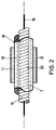
- Fig. 2
- einen schematischen, ausschnittsweisen Längsschnitt einer Elektrode in deren atrial zu plazierenden Teil,
- Fig. 3
- einen schematischen, ausschnittsweisen Längsschnitt der Elektrode im Bereich deren ventrikulär zu plazierenden Elektrodenkopfs,
- Fig. 4
- einen schematischen Querschnitt durch eine Elektroden sonde in einer weiteren Ausführungsform und
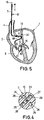
- Fig. 5
- einen schematischen Schnitt des Herzens mit einer pla zierten Elektrodensonde in einer weiteren alternativen Ausgestaltung.
- 1A to C
- schematic sectional representations of the heart with a single electrode probe in successive positioning steps,
- Fig. 2
- 2 shows a schematic, sectional longitudinal section of an electrode in its part to be placed atrially,
- Fig. 3
- 2 shows a schematic, partial longitudinal section of the electrode in the region of its electrode head to be placed ventricularly,
- Fig. 4
- a schematic cross section through an electrode probe in a further embodiment and
- Fig. 5
- a schematic section of the heart with a placed electrode probe in a further alternative embodiment.
In den Einzeldarstellungen der Fig. 1 ist jeweils das menschliche Herz 1 mit seinem rechten Atrium 2 und seinem rechten Ventrikel 3 sowie der Vene 4 und der Tricuspidalklappe 5 dargestellt.1 each shows the human heart 1 with its
Eine in Fig. 1 als Ganzes mit 6 bezeichnete Einzel-Elektrodensonde für DDD-Herzschrittmachersysteme weist einen schlauchartigen, flexiblen Sondenkörper 7 aus isolierendem Silikonmaterial auf. An der Spitze 8' des Elektrodenkopfes 8 ist eine erste ventrikuläre Elektrode 9 angeordnet. Ca. 2 bis 3 cm hinter dem Elektrodenkopf 8 sitzt auf dem Sondenkörper 7 eine ventrikuläre Ringelektrode 10, die zusammen mit der ventrikulären Elektrode 9 an der Elektrodenspitze 8' für eine bipolare Stimulation des Ventrikels sorgen kann.An individual electrode probe for DDD pacemaker systems, designated as a whole by 6 in FIG. 1, has a tube-like,
Etwa 10 bis 15 cm hinter dem Elektrodenkopf 8 sitzt ein zweites Elektrodenpaar, bestehend aus den beiden atrialen Ringelektroden 11, 12, die für eine bipolare Stimulierung des Atriums sorgen. Über die Elektroden 9 bis 12 ist im übrigen auch in üblicher Weise ein Sensing der elektrischen Signale im Herzmuskelgewebe möglich, wie sie durch die vom Sinusknoten 13 herrührenden und über den AV-Knoten 14 verzögert zum Ventrikel weitergeleiteten Eigenreize des Herzens hervorgerufen werden.About 10 to 15 cm behind the
Die Elektroden 9 bis 12 sind ferner in üblicher Weise über isoliert im Sondenkörper 7 geführte elektrische Zuleitungen 15 mit dem eigentlichen Herzschrittmachersystem (nicht dargestellt) verbunden. Von diesen elektrischen Zuleitungen 15 ist in den Fig. 2 und 3 der Übersichtlichkeit halber jeweils nur eine dieser Draht-Zuleitungen 15 gezeigt, die in der Regel wendelförmig angelegt sind. Diese Drahtwendeln bestehen meist aus einem Legierungswerkstoff der Bezeichnung MP35N.The
Wie in Fig. 1 ferner schematisch angedeutet ist, weist der Sondenkörper 7 ein zentrales Lumen auf, in das ein elastischer, jedoch relativ steif ausgelegter Führungsdraht 16 bis zur Elektrodenspitze 8' in den Sondenkörper 7 einschiebbar ist.As is also indicated schematically in FIG. 1, the
Mit Hilfe des vollständig eingeschobenen Führungsdrahtes 16, wie in Fig. 1A gezeigt, wird die Einzel-Elektrodensonde 6 durch einen entsprechenden Schnitt in der Vene 4 in im wesentlichen gestreckten Zustand zuerst in das rechte Atrium 2 und dann weiter über die Tricuspidalklappe 5 in das rechte Ventrikel 3 eingeschoben. Dieser Zustand ist in Fig. 1A dargestellt.With the aid of the completely inserted
Anschließend wird der Führungsdraht 16 einige Zentimeter aus dem Sondenkörper 7 herausgezogen, so daß im Bereich des Elektrodenkopfes 8 die Streckfunktion des Führungsdrahtes 16 entfällt. Demzufolge kann ein kurz hinter der Ringelektrode 10 angeordnetes, in Fig. 1B und C schraffiert angedeutetes Vorformelement 17 zur Wirkung kommen, dessen genaue Ausgestaltungsmöglichkeiten noch anhand der Fig. 2 bis 4 näher zu erläutern sind.The
Das Vorformelement 17 weist eine gebogene Grundform auf, so daß der Sondenkörper 7 zum Elektrodenkopf 8 hin den in Fig. 1B und C gezeigten J-förmigen Verlauf einnimmt. Demzufolge weist der Elektrodenkopf 8 schräg nach oben in Richtung des AV-Knotens und die Elektrode 9 kann in dessen direkter Nachbarschaft festgelegt werden.The
Wird der Führungsdraht 16 weiter über die atrialen Ringelektroden 11, 12 hinaus aus dem Sondenkörper 7 herausgezogen (Fig. 1C), so entfaltet ein zweites Vorformelement 18 seine Wirkung, das auf einer Teillänge von mehreren Zentimetern im atrialen Bereich des Sondenkörpers 7 angeordnet ist. Das Vorformelement 18 führt zu der in Fig. 1C dargestellten helixförmigen Ausgestaltung des Sondenkörpers 7 im rechten Atrium 2, wodurch sich der Sondenkörper 7 dort an die atriale Herzwand anlegen kann. Insofern liegt die atriale Ringelektrode 11 an der linken, innenseitigen Atrialwand unterhalb des Sinusknotens 13 an, wodurch die Sensing- und Stimulationseigenschaften der Elektrodensonde 6 gegenüber einer flottierenden Elektrode optimiert werden können.If the
Aufgrund des durch das Vorformelement 18 gegebenen Verlaufs des Sondenkörpers 7 im Atrium ist eine dauerhafte Positionierung des Sondenkörpers 7 in einer optimalen Position möglich, die auch nach dem vollständigen Herausziehen des Führungsdrahtes 16 zuverlässig aufrechterhalten wird.Due to the course of the
Es wird im übrigen eine dauerhafte Verankerung der Ringelektroden 11, 12 im Atrium 2 durch deren Einwachsen in die Atrialwand 30 erreicht, was mit der Zeit erfolgt. Um diesen Einwachsprozeß zu beschleunigen, sind nun die Ringelektroden 11, 12 - wie in Fig. 2 anhand der Elektrode 11 angedeutet ist - mit einer Beschichtung 31 versehen, die Collagen-Fasern aufweist.In addition, the
In dieser Fig. 2 ist eine mögliche Ausgestaltung für das Vorformelement 18 in extrem vergrößerter Darstellung gezeigt. Es handelt sich dabei um ein auf dem Sondenkörper 7 sitzendes Manschettenteil 19 aus isolierendem Silikon-Material, das in seinen Elastizitätseigenschaften steifer als der eigentliche Sondenkörper 7 und weniger steif als der Führungsdraht eingestellt ist. Das Manschettenteil 19 kann im angegebenen Bereich auf den Sondenkörper 7 aufgeschrumpft werden. Es erteilt dem Sondenkörper 7 die in Fig. 1C dargestellte Helixform.2 shows a possible configuration for the
Wie Fig. 2 ferner zu entnehmen ist, ist auf das Manschettenteil 19 die atriale Ringelektrode 11 aufgesetzt, die - wie nicht gezeigt ist - mit einer elektrischen Zuleitung versehen ist. In Fig. 2 ist lediglich eine elektrische Zuleitung 15 in Form eines gewendelten Drahtes dargestellt, der zur ventrikulären Elektrode 9 an der Elektrodenspitze 8 führt. In Fig. 2 ist ferner das Manschettenteil 19 in seiner aufgrund des in das Lumen 23 eingeführten Führungsdrahtes 16 geradlinig gestreckten Form gezeigt.As can also be seen in FIG. 2, the
Fig. 3 zeigt den Elektrodenkopf 8 mit der ventrikulären Elektrode 9 an der Spitze 8' und der dahinter angeordneten Ringelektrode 10. Das hinter der Ringelektrode 10 angeordnete Vorformelement 17 ist im gezeigten Beispiel in integraler Weise durch eine Vorformung der die elektrische Zuleitung für die ventrikuläre Elektrode 9 bildenden Drahtwendel 20 selbst gebildet. Dazu ist auf der Teillänge LT, von der in Fig. 3 lediglich der rechte Rand 21 gezeigt ist, die Drahtwendel 20 so gewickelt, daß sie in einem nicht beaufschlagten Zustand einen durch den Doppelpfeil 22 angedeuteten gebogenen Verlauf einnimmt. Dadurch wird die Biegung am Fuß der J-Form des Elektrodenkopfes 8 erzeugt. In Fig. 3 ist hingegen die Strecklage des Elektrodenkopfes 8 gezeigt, die durch den bis zur ventrikulären Elektrode 9 eingeschobenen Führungsdraht 16 hervorgerufen wird.3 shows the
In Fig. 4 ist eine weitere Ausführungsform für eine erfindungsgemäße Elektrodensonde im Schnitt dargestellt. Der aus isolierendem Silikonmaterial bestehende Sondenkörper 7 weist dabei fünf Lumen 23 bis 27 auf, wobei im zentralen Lumen 23 der Führungsdraht 16 sitzt. In den drei weiteren, außenliegenden Lumen 24, 25 und 26 verlaufen wendelförmig gebogene Zuleitungsdrähte 28 beispielsweise für eine ventrikuläre Elektrode an der Elektrodenspitze und eine ventrikuläre Ringelektrode sowie für eine atriale Ringelektrode. Diese Zuleitungsdrähte können auch sogenannte "DFT-Seile" sein, die aus einem elektrisch gut leitfähigen Silberkern und einer diesen umgebenden, mechanisch stabilen Wendel aus Medizinstahl MP35N bestehen.A further embodiment for an electrode probe according to the invention is shown in section in FIG. 4. The
Im verbleibenden Lumen 27 können Drahtwendeln 29 als Vorformelemente eingesetzt werden, die sich jeweils nur über die Teillängen im Atrium- bzw. Ventrikelbereich der Elektrodensonde 6 erstrecken, um eine dauerhafte Auslenkung aus der Strecklage z.B. entsprechend dem in Fig. 1C gezeigten Sondenverlauf zu erzielen.In the remaining
Die in Fig. 5 gezeigte Ausführungsform einer erfindungsgemäßen Elektrodensonde 6' weist statt des helixförmigen Vorformelementes 18 ein omegaförmiges Vorformelement 18' auf, so daß die Elektrodensonde eine im wesentlichen in einer Ebene ausgelenkte omegaförmige Gestalt im Bereich des Atriums aufweist. Das Vorformelement 18' kann dabei entweder in Form eines Manschettenteils oder in integraler Weise durch eine entsprechende Formgebung der die elektrische Kontaktierung z.B. für die atriale Ringelektrode 11 bildenden Drahtwendel ausgestaltet sein.The embodiment of an electrode probe 6 'according to the invention shown in FIG. 5 has an omega-shaped preform element 18' instead of the
Claims (10)
die Sonde (6, 6') zumindest auf einer im Atrium (2) des Herzens (1) zu plazierenden Teillänge derart mit einem Vorformelement (18, 18') versehen ist, daß bei eingeschobenem Führungsdraht (16) die Sonde (6, 6') im wesentlichen geradlinig gestreckt und bei herausgezogenem Führungsdraht (16) die Sonde auf der Teillänge eine aus der Streckrichtung ausgelenkte, durch das Vorformelement (18, 18') definierte Form annimmt, so daß die Sonde mit mindestens einer atrialen Elektrode (11, 12) an die Atrialwand (30) des Herzens (1) anlegbar ist.Single electrode probe for pacemaker systems, especially for DDD pacemaker systems, with:
the probe (6, 6 ') is provided with a preform element (18, 18') at least over a partial length to be placed in the atrium (2) of the heart (1) in such a way that the probe (6, 6 ') stretched substantially in a straight line and, when the guide wire (16) is pulled out, the probe over the partial length assumes a shape deflected from the stretching direction and defined by the preform element (18, 18'), so that the probe with at least one atrial electrode (11, 12 ) can be placed on the atrial wall (30) of the heart (1).
Applications Claiming Priority (2)
| Application Number | Priority Date | Filing Date | Title |
|---|---|---|---|
| DE19546941 | 1995-12-15 | ||
| DE19546941A DE19546941A1 (en) | 1995-12-15 | 1995-12-15 | Single electrode for two-chamber pacemaker systems, especially for DDD pacemaker systems |
Publications (2)
| Publication Number | Publication Date |
|---|---|
| EP0779079A1 true EP0779079A1 (en) | 1997-06-18 |
| EP0779079B1 EP0779079B1 (en) | 2004-03-31 |
Family
ID=7780272
Family Applications (1)
| Application Number | Title | Priority Date | Filing Date |
|---|---|---|---|
| EP96118563A Expired - Lifetime EP0779079B1 (en) | 1995-12-15 | 1996-11-20 | Single electrode lead for double-chamber cardiac stimulators, especially for DD cardiac stimulators |
Country Status (2)
| Country | Link |
|---|---|
| EP (1) | EP0779079B1 (en) |
| DE (2) | DE19546941A1 (en) |
Cited By (9)
| Publication number | Priority date | Publication date | Assignee | Title |
|---|---|---|---|---|
| WO1999042172A1 (en) * | 1998-02-18 | 1999-08-26 | Intermedics, Inc. | Implantable cardiac lead with multiple shape memory polymer structures |
| EP1285678A2 (en) | 2001-08-23 | 2003-02-26 | BIOTRONIK Mess- und Therapiegeräte GmbH & Co Ingenieurbüro Berlin | Single electrode lead for pacemaker systems |
| US9675413B2 (en) | 2002-04-08 | 2017-06-13 | Medtronic Ardian Luxembourg S.A.R.L. | Methods and apparatus for renal neuromodulation |
| US9707035B2 (en) | 2002-04-08 | 2017-07-18 | Medtronic Ardian Luxembourg S.A.R.L. | Methods for catheter-based renal neuromodulation |
| US9855096B2 (en) | 2012-05-11 | 2018-01-02 | Medtronic Ardian Luxembourg S.A.R.L. | Multi-electrode catheter assemblies for renal neuromodulation and associated systems and methods |
| US9888961B2 (en) | 2013-03-15 | 2018-02-13 | Medtronic Ardian Luxembourg S.A.R.L. | Helical push wire electrode |
| US10076382B2 (en) | 2010-10-25 | 2018-09-18 | Medtronic Ardian Luxembourg S.A.R.L. | Catheter apparatuses having multi-electrode arrays for renal neuromodulation and associated systems and methods |
| US10736690B2 (en) | 2014-04-24 | 2020-08-11 | Medtronic Ardian Luxembourg S.A.R.L. | Neuromodulation catheters and associated systems and methods |
| US11213678B2 (en) | 2013-09-09 | 2022-01-04 | Medtronic Ardian Luxembourg S.A.R.L. | Method of manufacturing a medical device for neuromodulation |
Families Citing this family (6)
| Publication number | Priority date | Publication date | Assignee | Title |
|---|---|---|---|---|
| DE19800697B4 (en) * | 1998-01-10 | 2009-04-02 | Biotronik Gmbh & Co. Kg | Single electrode probe, especially for implantable defibrillators |
| US6702811B2 (en) | 1999-04-05 | 2004-03-09 | Medtronic, Inc. | Ablation catheter assembly with radially decreasing helix and method of use |
| DE10011572A1 (en) | 2000-03-02 | 2001-09-06 | Biotronik Mess & Therapieg | Electrode arrangement |
| DE10118797A1 (en) | 2001-04-05 | 2002-10-17 | Biotronik Mess & Therapieg | electrode line |
| US8774913B2 (en) | 2002-04-08 | 2014-07-08 | Medtronic Ardian Luxembourg S.A.R.L. | Methods and apparatus for intravasculary-induced neuromodulation |
| US9095321B2 (en) | 2012-11-21 | 2015-08-04 | Medtronic Ardian Luxembourg S.A.R.L. | Cryotherapeutic devices having integral multi-helical balloons and methods of making the same |
Citations (5)
| Publication number | Priority date | Publication date | Assignee | Title |
|---|---|---|---|---|
| US4154247A (en) * | 1977-04-01 | 1979-05-15 | Medtronic, Inc. | Formable cardiac pacer lead and method of assembly and attachment to a body organ |
| WO1980002801A1 (en) * | 1979-06-14 | 1980-12-24 | B Reenstierna | Endocardial,implantable lead for pacemaker |
| GB2116047A (en) * | 1982-02-27 | 1983-09-21 | John Stafford Geddes | Catheter |
| US4567901A (en) * | 1983-12-15 | 1986-02-04 | Cordis Corporation | Prebent ventricular/atrial cardiac pacing lead |
| EP0656218A1 (en) * | 1993-12-03 | 1995-06-07 | Pacesetter AB | Electrode system |
Family Cites Families (8)
| Publication number | Priority date | Publication date | Assignee | Title |
|---|---|---|---|---|
| US3596662A (en) * | 1968-09-04 | 1971-08-03 | Medtronic Inc | Electrode for cardiac stimulator |
| US4497326A (en) * | 1981-04-06 | 1985-02-05 | Curry Paul V L | Heart pacing lead |
| US4488561A (en) * | 1983-06-27 | 1984-12-18 | Medtronic, Inc. | Pacing lead with insertable memory coil |
| EP0159753A1 (en) * | 1984-04-16 | 1985-10-30 | Eliezer A. Astrinski | Cardiac lead |
| US5172694A (en) * | 1991-05-30 | 1992-12-22 | Vitatron Medical B.V. | Single pacing lead and method utilizing two different floating bipoles |
| EP0559933A1 (en) * | 1992-03-10 | 1993-09-15 | Pacesetter AB | Electrode assembly for an implantable defibrillator/cardioverter |
| US5387233A (en) * | 1993-01-11 | 1995-02-07 | Incontrol, Inc. | Intravenous cardiac lead with improved fixation and method |
| SE9302476D0 (en) * | 1993-07-22 | 1993-07-22 | Siemens-Elema Ab | DEVICE FOR SHAPING AN ELECTRIC CABLE |
-
1995
- 1995-12-15 DE DE19546941A patent/DE19546941A1/en not_active Withdrawn
-
1996
- 1996-11-20 DE DE59610952T patent/DE59610952D1/en not_active Expired - Lifetime
- 1996-11-20 EP EP96118563A patent/EP0779079B1/en not_active Expired - Lifetime
Patent Citations (5)
| Publication number | Priority date | Publication date | Assignee | Title |
|---|---|---|---|---|
| US4154247A (en) * | 1977-04-01 | 1979-05-15 | Medtronic, Inc. | Formable cardiac pacer lead and method of assembly and attachment to a body organ |
| WO1980002801A1 (en) * | 1979-06-14 | 1980-12-24 | B Reenstierna | Endocardial,implantable lead for pacemaker |
| GB2116047A (en) * | 1982-02-27 | 1983-09-21 | John Stafford Geddes | Catheter |
| US4567901A (en) * | 1983-12-15 | 1986-02-04 | Cordis Corporation | Prebent ventricular/atrial cardiac pacing lead |
| EP0656218A1 (en) * | 1993-12-03 | 1995-06-07 | Pacesetter AB | Electrode system |
Non-Patent Citations (1)
| Title |
|---|
| J. HIRSCHBERG ET AL.: "New Dual Chamber Single Lead System", FACHZEITSCHRIFT "PACE", November 1994 (1994-11-01), pages 1870 - 1872, XP000613855, DOI: doi:10.1111/j.1540-8159.1994.tb03765.x |
Cited By (15)
| Publication number | Priority date | Publication date | Assignee | Title |
|---|---|---|---|---|
| WO1999042172A1 (en) * | 1998-02-18 | 1999-08-26 | Intermedics, Inc. | Implantable cardiac lead with multiple shape memory polymer structures |
| EP1285678A2 (en) | 2001-08-23 | 2003-02-26 | BIOTRONIK Mess- und Therapiegeräte GmbH & Co Ingenieurbüro Berlin | Single electrode lead for pacemaker systems |
| EP1285678A3 (en) * | 2001-08-23 | 2003-07-23 | BIOTRONIK Mess- und Therapiegeräte GmbH & Co Ingenieurbüro Berlin | Single electrode lead for pacemaker systems |
| US7047086B2 (en) | 2001-08-23 | 2006-05-16 | BIOTRONIK Mess-und Therapiegerä{umlaut over ( )}te GmbH & Co. Ingenieurbü{umlaut over ( )}ro | Single electrode probe for a cardiac pacemaker system |
| US9675413B2 (en) | 2002-04-08 | 2017-06-13 | Medtronic Ardian Luxembourg S.A.R.L. | Methods and apparatus for renal neuromodulation |
| US9707035B2 (en) | 2002-04-08 | 2017-07-18 | Medtronic Ardian Luxembourg S.A.R.L. | Methods for catheter-based renal neuromodulation |
| US10076382B2 (en) | 2010-10-25 | 2018-09-18 | Medtronic Ardian Luxembourg S.A.R.L. | Catheter apparatuses having multi-electrode arrays for renal neuromodulation and associated systems and methods |
| US11116572B2 (en) | 2010-10-25 | 2021-09-14 | Medtronic Ardian Luxembourg S.A.R.L. | Catheter apparatuses having multi-electrode arrays for renal neuromodulation and associated systems and methods |
| US9855096B2 (en) | 2012-05-11 | 2018-01-02 | Medtronic Ardian Luxembourg S.A.R.L. | Multi-electrode catheter assemblies for renal neuromodulation and associated systems and methods |
| US10512504B2 (en) | 2012-05-11 | 2019-12-24 | Medtronic Ardian Luxembourg S.A.R.L. | Multi-electrode catheter assemblies for renal neuromodulation and associated systems and methods |
| US10792098B2 (en) | 2013-03-15 | 2020-10-06 | Medtronic Ardian Luxembourg S.A.R.L. | Helical push wire electrode |
| US9888961B2 (en) | 2013-03-15 | 2018-02-13 | Medtronic Ardian Luxembourg S.A.R.L. | Helical push wire electrode |
| US11213678B2 (en) | 2013-09-09 | 2022-01-04 | Medtronic Ardian Luxembourg S.A.R.L. | Method of manufacturing a medical device for neuromodulation |
| US10736690B2 (en) | 2014-04-24 | 2020-08-11 | Medtronic Ardian Luxembourg S.A.R.L. | Neuromodulation catheters and associated systems and methods |
| US11464563B2 (en) | 2014-04-24 | 2022-10-11 | Medtronic Ardian Luxembourg S.A.R.L. | Neuromodulation catheters and associated systems and methods |
Also Published As
| Publication number | Publication date |
|---|---|
| DE59610952D1 (en) | 2004-05-06 |
| DE19546941A1 (en) | 1997-06-19 |
| EP0779079B1 (en) | 2004-03-31 |
Similar Documents
| Publication | Publication Date | Title |
|---|---|---|
| DE60019908T2 (en) | coronary sinus | |
| DE69627290T2 (en) | Implantable electrode cable with at least one electrode contact | |
| DE69725302T2 (en) | MEDICAL ELECTRICAL LINE | |
| DE60017716T2 (en) | COEXTRUDED MEDICAL MULTILUMENLINE | |
| EP1038547B1 (en) | Expandable cardiac lead for implantation in the coronary sinus | |
| EP0951920B1 (en) | Electrode cable for attachement to a vessel wall | |
| DE69836622T2 (en) | PACE MANAGEMENT FOR LATERAL INTRODUCTION | |
| DE19957241B4 (en) | Electric cable for medical purposes and system for introducing same | |
| DE69833361T2 (en) | Medical electrical supply | |
| DE3914662C2 (en) | ||
| DE69823530T2 (en) | MEDICAL ELECTRICAL SUPPLY | |
| DE69928498T2 (en) | INTRAVENOUS HEADLINE WITH REINFORCED FASTENING ELEMENT | |
| EP0779079B1 (en) | Single electrode lead for double-chamber cardiac stimulators, especially for DD cardiac stimulators | |
| DE19609471A1 (en) | Electrode arrangement | |
| DE10058106A1 (en) | Medical electrical line with in the direction of the distant increasing bending stiffness | |
| DE10058105A1 (en) | Medical electrical cable with variable bending stiffness | |
| DE60016512T2 (en) | Implantable electrode lead | |
| EP2674189A1 (en) | Implantable electrode pole | |
| EP2143464B1 (en) | Implantable electrode lead or electrode lead device | |
| EP1618917B1 (en) | Stimulation electrode lead | |
| EP1285678B1 (en) | Single electrode lead for pacemaker systems | |
| EP1595571B1 (en) | Electrode lead | |
| EP2862594A1 (en) | Active, reversible fixing of CRT electrodes | |
| EP1247543A2 (en) | Electrode lead | |
| EP2497526B1 (en) | Implantable electrode lead |
Legal Events
| Date | Code | Title | Description |
|---|---|---|---|
| PUAI | Public reference made under article 153(3) epc to a published international application that has entered the european phase |
Free format text: ORIGINAL CODE: 0009012 |
|
| AK | Designated contracting states |
Kind code of ref document: A1 Designated state(s): CH DE FR GB LI NL |
|
| 17P | Request for examination filed |
Effective date: 19971002 |
|
| 17Q | First examination report despatched |
Effective date: 20020620 |
|
| GRAP | Despatch of communication of intention to grant a patent |
Free format text: ORIGINAL CODE: EPIDOSNIGR1 |
|
| GRAS | Grant fee paid |
Free format text: ORIGINAL CODE: EPIDOSNIGR3 |
|
| GRAA | (expected) grant |
Free format text: ORIGINAL CODE: 0009210 |
|
| AK | Designated contracting states |
Kind code of ref document: B1 Designated state(s): CH DE FR GB LI NL |
|
| REG | Reference to a national code |
Ref country code: GB Ref legal event code: FG4D Free format text: NOT ENGLISH Ref country code: CH Ref legal event code: EP |
|
| GBT | Gb: translation of ep patent filed (gb section 77(6)(a)/1977) | ||
| REF | Corresponds to: |
Ref document number: 59610952 Country of ref document: DE Date of ref document: 20040506 Kind code of ref document: P |
|
| ET | Fr: translation filed | ||
| PLBE | No opposition filed within time limit |
Free format text: ORIGINAL CODE: 0009261 |
|
| STAA | Information on the status of an ep patent application or granted ep patent |
Free format text: STATUS: NO OPPOSITION FILED WITHIN TIME LIMIT |
|
| 26N | No opposition filed |
Effective date: 20050104 |
|
| PGFP | Annual fee paid to national office [announced via postgrant information from national office to epo] |
Ref country code: NL Payment date: 20071121 Year of fee payment: 12 |
|
| PGFP | Annual fee paid to national office [announced via postgrant information from national office to epo] |
Ref country code: CH Payment date: 20071126 Year of fee payment: 12 |
|
| PGFP | Annual fee paid to national office [announced via postgrant information from national office to epo] |
Ref country code: GB Payment date: 20071123 Year of fee payment: 12 Ref country code: FR Payment date: 20071120 Year of fee payment: 12 |
|
| REG | Reference to a national code |
Ref country code: CH Ref legal event code: PL |
|
| GBPC | Gb: european patent ceased through non-payment of renewal fee |
Effective date: 20081120 |
|
| PG25 | Lapsed in a contracting state [announced via postgrant information from national office to epo] |
Ref country code: NL Free format text: LAPSE BECAUSE OF NON-PAYMENT OF DUE FEES Effective date: 20090601 |
|
| NLV4 | Nl: lapsed or anulled due to non-payment of the annual fee |
Effective date: 20090601 |
|
| REG | Reference to a national code |
Ref country code: FR Ref legal event code: ST Effective date: 20090731 |
|
| PG25 | Lapsed in a contracting state [announced via postgrant information from national office to epo] |
Ref country code: LI Free format text: LAPSE BECAUSE OF NON-PAYMENT OF DUE FEES Effective date: 20081130 Ref country code: CH Free format text: LAPSE BECAUSE OF NON-PAYMENT OF DUE FEES Effective date: 20081130 |
|
| PG25 | Lapsed in a contracting state [announced via postgrant information from national office to epo] |
Ref country code: GB Free format text: LAPSE BECAUSE OF NON-PAYMENT OF DUE FEES Effective date: 20081120 |
|
| PG25 | Lapsed in a contracting state [announced via postgrant information from national office to epo] |
Ref country code: FR Free format text: LAPSE BECAUSE OF NON-PAYMENT OF DUE FEES Effective date: 20081130 |
|
| REG | Reference to a national code |
Ref country code: DE Ref legal event code: R082 Ref document number: 59610952 Country of ref document: DE |
|
| REG | Reference to a national code |
Ref country code: DE Ref legal event code: R081 Ref document number: 59610952 Country of ref document: DE Owner name: BIOTRONIK SE & CO. KG, DE Free format text: FORMER OWNER: BIOTRONIK MESS- UND THERAPIEGERAETE GMBH & CO. INGENIEURBUERO BERLIN, 12359 BERLIN, DE Effective date: 20111219 |
|
| PGFP | Annual fee paid to national office [announced via postgrant information from national office to epo] |
Ref country code: DE Payment date: 20121109 Year of fee payment: 17 |
|
| PG25 | Lapsed in a contracting state [announced via postgrant information from national office to epo] |
Ref country code: DE Free format text: LAPSE BECAUSE OF NON-PAYMENT OF DUE FEES Effective date: 20140603 |
|
| REG | Reference to a national code |
Ref country code: DE Ref legal event code: R119 Ref document number: 59610952 Country of ref document: DE Effective date: 20140603 |