EP0780785A2 - Shutter control mechanism - Google Patents
Shutter control mechanism Download PDFInfo
- Publication number
- EP0780785A2 EP0780785A2 EP96309259A EP96309259A EP0780785A2 EP 0780785 A2 EP0780785 A2 EP 0780785A2 EP 96309259 A EP96309259 A EP 96309259A EP 96309259 A EP96309259 A EP 96309259A EP 0780785 A2 EP0780785 A2 EP 0780785A2
- Authority
- EP
- European Patent Office
- Prior art keywords
- shutter
- open
- cam
- closed
- pin
- Prior art date
- Legal status (The legal status is an assumption and is not a legal conclusion. Google has not performed a legal analysis and makes no representation as to the accuracy of the status listed.)
- Withdrawn
Links
- 230000007246 mechanism Effects 0.000 title claims abstract description 17
- 101100492805 Caenorhabditis elegans atm-1 gene Proteins 0.000 description 4
- 230000000994 depressogenic effect Effects 0.000 description 2
- 230000000694 effects Effects 0.000 description 2
- 230000004048 modification Effects 0.000 description 1
- 238000012986 modification Methods 0.000 description 1
- 230000003287 optical effect Effects 0.000 description 1
- 238000009416 shuttering Methods 0.000 description 1
Images

Classifications
-
- G—PHYSICS
- G06—COMPUTING; CALCULATING OR COUNTING
- G06K—GRAPHICAL DATA READING; PRESENTATION OF DATA; RECORD CARRIERS; HANDLING RECORD CARRIERS
- G06K13/00—Conveying record carriers from one station to another, e.g. from stack to punching mechanism
- G06K13/02—Conveying record carriers from one station to another, e.g. from stack to punching mechanism the record carrier having longitudinal dimension comparable with transverse dimension, e.g. punched card
- G06K13/08—Feeding or discharging cards
- G06K13/0868—Feeding or discharging cards using an arrangement for keeping the feeding or insertion slot of the card station clean of dirt, or to avoid feeding of foreign or unwanted objects into the slot
- G06K13/0875—Feeding or discharging cards using an arrangement for keeping the feeding or insertion slot of the card station clean of dirt, or to avoid feeding of foreign or unwanted objects into the slot the arrangement comprising a shutter for blocking at least part of the card insertion slot
-
- G—PHYSICS
- G06—COMPUTING; CALCULATING OR COUNTING
- G06K—GRAPHICAL DATA READING; PRESENTATION OF DATA; RECORD CARRIERS; HANDLING RECORD CARRIERS
- G06K13/00—Conveying record carriers from one station to another, e.g. from stack to punching mechanism
- G06K13/02—Conveying record carriers from one station to another, e.g. from stack to punching mechanism the record carrier having longitudinal dimension comparable with transverse dimension, e.g. punched card
- G06K13/08—Feeding or discharging cards
-
- G—PHYSICS
- G07—CHECKING-DEVICES
- G07F—COIN-FREED OR LIKE APPARATUS
- G07F19/00—Complete banking systems; Coded card-freed arrangements adapted for dispensing or receiving monies or the like and posting such transactions to existing accounts, e.g. automatic teller machines
- G07F19/20—Automatic teller machines [ATMs]
- G07F19/201—Accessories of ATMs
-
- G—PHYSICS
- G07—CHECKING-DEVICES
- G07F—COIN-FREED OR LIKE APPARATUS
- G07F19/00—Complete banking systems; Coded card-freed arrangements adapted for dispensing or receiving monies or the like and posting such transactions to existing accounts, e.g. automatic teller machines
- G07F19/20—Automatic teller machines [ATMs]
- G07F19/205—Housing aspects of ATMs
Definitions
- This invention relates to shutter control mechanisms of the kind for controlling the movement of a shutter between closed and open positions, which respectively close and open an aperture.
- the aperture may, when the shutter is in the open position, permit passage of a data card of the kind used in automated teller machines (ATMs) such as are commonly provided for dispensing cash and for other financial transactions.
- ATMs automated teller machines
- the aperture is blocked and a data card or other object cannot be inserted into the aperture.
- a known shutter mechanism used in an ATM includes a pivoted blade which is spring-biased to the shutter closed position, but may be pivoted to the shutter open position by a force provided by a solenoid, for example.
- the known shutter mechanism has the disadvantage that a potentially fraudulent person may force the shutter open from the exterior of the ATM, against the action of the spring urging the shutter closed.
- a strong spring is provided to attempt to alleviate this problem, additional energy is required to be provided to overcome the force of the spring when the shutter is moved to the open position.
- a powerful electromagnetic device may need to be provided, for example.
- a shutter mechanism including a pivotally mounted shutter adapted to pivot about a support so that a blade portion of the shutter can move between open and closed positions wherein an aperture adapted for the passage of a data card is respectively open and closed, characterized in that a cam groove track on a rotatable cam wheel engages a pin on the shutter, the groove track having extreme near locations and extreme distant locations relative to the axis of rotation of the cam wheel, such that movement of the shutter pin in the groove track causes the shutter to pivot about its support and be driven to and locked at corresponding open and shut positions of the shutter.
- an ATM 1 has a card input slot 2 for receiving a data card, e.g. carrying identification and financial information of the card user in magnetically coded form, a key pad 3 for inputting data by the card user, a cash dispensing slot 4 and an output slot 5 for printed transaction and accounts data for the card user.
- the present invention concerns the shuttering of the input slot 2 so that unauthorised or unsuitable cards, and other undesirable objects are hindered from reaching the interior of the ATM 1 and the card reading station.
- the slot 2 has received a card 6 and a shutter blade 7, in its raised, open position, permits passage of the card 6 to the nip between belts driven by driving rollers 8,9 so that the card is conveyed to a magnetic reading and writing station (not shown).
- the card 6 may be initially checked for the presence of a magnetic stripe by a sensor 13 which controls the raising of the shutter blade 7, and an optical sensor 14 may signal the passage of the leading edge of the card 2, to control further card processing functions.
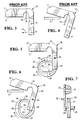
- Fig. 3 and 4 show a prior art shutter mechanism
- the shutter blade 7 of a shutter 19 closes (Fig.3) or opens (Fig.4) the entry aperture, such as the slot 2 of the ATM 1 of Fig.1.
- the shutter 19 is opened by clockwise rotation about a pivot axis 15, on which the shutter 19 is pivotally mounted, by a driving force, such as an electromagnetic device, represented by arrow 16 applied at a drive mounting 17, against the anticlockwise bias of a spring 18 tending to close the shutter.
- a driving force such as an electromagnetic device, represented by arrow 16 applied at a drive mounting 17, against the anticlockwise bias of a spring 18 tending to close the shutter.
- Considerable energy is employed to open the shutter, and its closure may be unnecessarily powerful, due to the strength of the spring 18.
- a shutter 20 has a first arm 21 providing a shutter blade 37 and a second arm 22, perpendicular to the first arm 21, which is pivotally mounted on a shaft 35.
- the shutter blade 37 closes or opens the entry aperture slot 2 of the ATM 1 of Fig.1.
- the opening and closing mechanism is different and a bias spring is not needed, although in a modification, a weak bias spring may be provided, to obviate the effects of wear and backlash.
- the opening and closing mechanism comprises a cam wheel 23 rotatable clockwise as shown by the arrow 36, and carrying a double acting cam surface in the form of a groove track 24 shaped in a elongated closed loop.
- the cam wheel 23 is fixedly mounted on a drive shaft 25, which forms an axis of rotation for the cam wheel.
- the groove track 24 has two locations 26,27 which are relatively distant form the drive shaft 25 and two locations 28,29 which form re-entrant or depressed regions nearer the drive shaft 25.
- a drive pin 30 on the shutter arm 22 is located in the groove track 24 and this follows the track between one of the distant locations 26,27 and one of the form rentrant or depressed regions nearer locations 28,29, for opening the shutter 20, causing the shutter 20 to pivot about the shaft 35. This is illustrated in Fig.5 which shows the shutter drive pin 30 in the distant location 27 of the groove track 24 thus locking the shutter 20 shut, with the entry aperture 2 closed by the shutter blade 37.
- the shutter mechanism could be arranged so that the distant locations 26,27 of the groove 24 could drive the cam 23 into the shutter open position and the near locations 28,29 would then bring the shutter into the closed position.
- the shutter need not have the form of two arms at right angles, provided that the blade 37, the pivot 35 and the drive pin 30 are spaced from one another on the shutter 20, such that the shutter and groove track geometries allow the necessary movements to open and close the shutter.
Abstract
Description
- This invention relates to shutter control mechanisms of the kind for controlling the movement of a shutter between closed and open positions, which respectively close and open an aperture.
- In one application, the aperture may, when the shutter is in the open position, permit passage of a data card of the kind used in automated teller machines (ATMs) such as are commonly provided for dispensing cash and for other financial transactions. When the shutter is in the closed position, the aperture is blocked and a data card or other object cannot be inserted into the aperture.
- A known shutter mechanism used in an ATM includes a pivoted blade which is spring-biased to the shutter closed position, but may be pivoted to the shutter open position by a force provided by a solenoid, for example. The known shutter mechanism has the disadvantage that a potentially fraudulent person may force the shutter open from the exterior of the ATM, against the action of the spring urging the shutter closed. Furthermore, if a strong spring is provided to attempt to alleviate this problem, additional energy is required to be provided to overcome the force of the spring when the shutter is moved to the open position. Thus, a powerful electromagnetic device may need to be provided, for example.
- It is an object of the present invention to provide a shutter control mechanism which is resistant to attempts to open the shutter in an unauthorised manner, yet has a low operative power requirement.
- Therefore, according to the present invention, there is provided a shutter mechanism including a pivotally mounted shutter adapted to pivot about a support so that a blade portion of the shutter can move between open and closed positions wherein an aperture adapted for the passage of a data card is respectively open and closed, characterized in that a cam groove track on a rotatable cam wheel engages a pin on the shutter, the groove track having extreme near locations and extreme distant locations relative to the axis of rotation of the cam wheel, such that movement of the shutter pin in the groove track causes the shutter to pivot about its support and be driven to and locked at corresponding open and shut positions of the shutter.
- One embodiment of the invention will now be described by way of example, with reference to the accompanying drawings, in which:-
- Fig.1 shows a perspective view of an ATM having a card slot which may be closed or opened by a shutter;
- Fig.2 shows a side view of the card slot, a shutter and a card en route to a checking or reading station;
- Fig.3 and 4 shows a prior art semaphore shutter viewed parallel to its pivotal axis in respectively closed and open positions;
- Fig.5 and 6 show a shutter and cam wheel embodying the invention viewed similarly and in respective similar positions to the prior art system of Figs.3 and 4; and
- Fig.7 is a side view of the shutter shown in Figs.5 and 6 in the closed position shown in Fig.5.
- Referring to Fig.1, an
ATM 1 has acard input slot 2 for receiving a data card, e.g. carrying identification and financial information of the card user in magnetically coded form, akey pad 3 for inputting data by the card user, acash dispensing slot 4 and anoutput slot 5 for printed transaction and accounts data for the card user. The present invention concerns the shuttering of theinput slot 2 so that unauthorised or unsuitable cards, and other undesirable objects are hindered from reaching the interior of theATM 1 and the card reading station. - Referring to Fig.2 the
slot 2 has received acard 6 and ashutter blade 7, in its raised, open position, permits passage of thecard 6 to the nip between belts driven bydriving rollers card 6 may be initially checked for the presence of a magnetic stripe by asensor 13 which controls the raising of theshutter blade 7, and anoptical sensor 14 may signal the passage of the leading edge of thecard 2, to control further card processing functions. - Referring now to Fig. 3 and 4, which show a prior art shutter mechanism, the
shutter blade 7 of ashutter 19 closes (Fig.3) or opens (Fig.4) the entry aperture, such as theslot 2 of theATM 1 of Fig.1. Theshutter 19 is opened by clockwise rotation about apivot axis 15, on which theshutter 19 is pivotally mounted, by a driving force, such as an electromagnetic device, represented byarrow 16 applied at a drive mounting 17, against the anticlockwise bias of aspring 18 tending to close the shutter. Considerable energy is employed to open the shutter, and its closure may be unnecessarily powerful, due to the strength of thespring 18. - Referring to the embodiment of the invention shown in Figs. 5,6 and 7, a
shutter 20 has afirst arm 21 providing ashutter blade 37 and asecond arm 22, perpendicular to thefirst arm 21, which is pivotally mounted on ashaft 35. Theshutter blade 37 closes or opens theentry aperture slot 2 of theATM 1 of Fig.1. Thus far the shutter resembles the known shutter of Fig.3 and 4, but the opening and closing mechanism is different and a bias spring is not needed, although in a modification, a weak bias spring may be provided, to obviate the effects of wear and backlash. - The opening and closing mechanism comprises a
cam wheel 23 rotatable clockwise as shown by thearrow 36, and carrying a double acting cam surface in the form of agroove track 24 shaped in a elongated closed loop. Thecam wheel 23 is fixedly mounted on adrive shaft 25, which forms an axis of rotation for the cam wheel. Thegroove track 24 has twolocations drive shaft 25 and twolocations drive shaft 25. Adrive pin 30 on theshutter arm 22 is located in thegroove track 24 and this follows the track between one of thedistant locations nearer locations shutter 20, causing theshutter 20 to pivot about theshaft 35. This is illustrated in Fig.5 which shows theshutter drive pin 30 in thedistant location 27 of thegroove track 24 thus locking theshutter 20 shut, with theentry aperture 2 closed by theshutter blade 37. - When the
cam wheel 23 has rotated through approximately 90 degrees, in the direction of thearrow 36, the shutter mechanism will have adopted the position seen in Fig.6, where thepin 30 is in thenear location 28 of thecam groove track 24, and theshutter 20 has rotated clockwise so that theblade 37 no longer obstructs theaperture 2. A subsequent further clockwise movement of thecam wheel 23 will rotate theshutter 20 anticlockwise until theaperture 2 is again closed. Thedistant location 26 with respect to thedrive shaft 25 will now be engaging thepin 30. Fig.7 shows more clearly theshaft 35 andpin 30 in a side view of the shutter closed condition of Fig.5. - It will be appreciated that the shutter mechanism could be arranged so that the
distant locations groove 24 could drive thecam 23 into the shutter open position and thenear locations blade 37, thepivot 35 and thedrive pin 30 are spaced from one another on theshutter 20, such that the shutter and groove track geometries allow the necessary movements to open and close the shutter. As mentioned, there may be a small bias spring (not shown) providing a closing bias on the shutter, to counteract wear and backlash. It should be understood that these effects are in fact minimized by the preferred arrangement since the cam is always driven in the same direction. It will be appreciated that theshutter 20 is always positively locked, whether open or shut, without expenditure of power.
Claims (5)
- A shutter mechanism including a pivotally mounted shutter (20) adapted to pivot about a support (35) so that a blade portion (37) of the shutter (20) can move between open and closed positions wherein an aperture (2) adapted for the passage of a data card (6) is respectively open and closed, characterized in that a cam groove track (24) on a rotatable cam wheel (23) engages a pin (30) on the shutter (20), the groove track (24) having extreme near locations (28,29) and extreme distant locations (26,27) relative to the axis (25) of rotation of the cam wheel (23), such that movement of the shutter pin (30) in the groove track (24) causes the shutter (20) to pivot about its support (35) and be driven to and locked at corresponding open and shut positions of the shutter (20).
- A shutter mechanism according to claim 1, characterized in that a first arm (21) of the shutter (20) carries the blade (37) which, at the extreme positions of movement of the shutter (20) opens and closes the aperture (2), a second arm (22) of the shutter being inclined to the first arm (21) and the shutter pin (30) and pivotal shutter mounting being located at spaced locations on the second arm (22).
- A shutter mechanism according to claim 1 or claim 2, characterized in that the cam groove track (24) has the form of a closed elongated loop having two near locations (28,29) and two distant locations (26,27) relative to the cam axis (25), providing two open and two closed positions of the shutter (20) per revolution of the cam wheel (23).
- A shutter mechanism according to any one of the preceding claims, characterized in that the cam wheel (23) is adapted to be rotated in one direction only.
- A shutter mechanism according to any one of the preceding claims, characterized by a bias spring adapted to bias the shutter (20) towards the shutter closed position.
Applications Claiming Priority (2)
| Application Number | Priority Date | Filing Date | Title |
|---|---|---|---|
| GBGB9526337.2A GB9526337D0 (en) | 1995-12-22 | 1995-12-22 | Shutter control mechanism |
| GB9526337 | 1995-12-22 |
Publications (2)
| Publication Number | Publication Date |
|---|---|
| EP0780785A2 true EP0780785A2 (en) | 1997-06-25 |
| EP0780785A3 EP0780785A3 (en) | 1999-04-28 |
Family
ID=10785936
Family Applications (1)
| Application Number | Title | Priority Date | Filing Date |
|---|---|---|---|
| EP96309259A Withdrawn EP0780785A3 (en) | 1995-12-22 | 1996-12-18 | Shutter control mechanism |
Country Status (5)
| Country | Link |
|---|---|
| US (1) | US5721420A (en) |
| EP (1) | EP0780785A3 (en) |
| JP (1) | JPH09218969A (en) |
| GB (1) | GB9526337D0 (en) |
| ZA (1) | ZA9610556B (en) |
Cited By (3)
| Publication number | Priority date | Publication date | Assignee | Title |
|---|---|---|---|---|
| WO2000041129A1 (en) * | 1998-12-31 | 2000-07-13 | Amphenol-Tuchel Electronics Gmbh | Card blocking device for a smart card connector |
| EP1604929A1 (en) * | 1998-10-06 | 2005-12-14 | Kabushiki Kaisha Nippon Conlux | Bank-note processing device |
| EP2400470A1 (en) * | 2010-06-22 | 2011-12-28 | Wincor Nixdorf International GmbH | Arrangement for closing an opening for the output and/or input of notes of an automated teller machine |
Families Citing this family (23)
| Publication number | Priority date | Publication date | Assignee | Title |
|---|---|---|---|---|
| US6328206B1 (en) * | 1997-11-28 | 2001-12-11 | Diebold, Incorporated | Adjustable display mounting mechanism for automated banking machine |
| JP3484652B2 (en) * | 1998-01-28 | 2004-01-06 | 富士通株式会社 | A shutter device having a link mechanism for opening and closing and fixing the shutter |
| US7240827B2 (en) * | 2002-11-26 | 2007-07-10 | Diebold, Incorporated | Automated banking machine with improved resistance to fraud |
| US5967264A (en) | 1998-05-01 | 1999-10-19 | Ncr Corporation | Method of monitoring item shuffling in a post-scan area of a self-service checkout terminal |
| US6042007A (en) * | 1998-10-16 | 2000-03-28 | Ncr Corporation | Self-service computer assembly with integrated receipt printer |
| US6296185B1 (en) | 1999-11-02 | 2001-10-02 | Ncr Corporation | Apparatus and method for operating a checkout system having a display monitor which displays both transaction information and customer-specific messages during a checkout transaction |
| GB2363890A (en) * | 2000-06-24 | 2002-01-09 | Ncr Int Inc | Self service terminal with a media entry aperture of variable size |
| US6736319B2 (en) * | 2001-09-04 | 2004-05-18 | Renaissance Learning, Inc. | Optical mark reader |
| JP4620382B2 (en) * | 2004-06-07 | 2011-01-26 | 沖電気工業株式会社 | Shutter mechanism and automatic transaction apparatus including the mechanism |
| KR100610806B1 (en) * | 2004-06-29 | 2006-08-08 | 노틸러스효성 주식회사 | Device of shutter opening and closing for financial automated-teller machine |
| EP1717764B1 (en) * | 2005-02-25 | 2014-10-01 | Astrosys International Ltd. | Foreign object detection |
| KR20060112461A (en) * | 2005-04-27 | 2006-11-01 | 노틸러스효성 주식회사 | Apparatus of operating a shutter in a cash transaction machine |
| JP4832920B2 (en) * | 2006-02-28 | 2011-12-07 | 富士通株式会社 | Shutter opening and closing device |
| US20090232419A1 (en) * | 2008-03-13 | 2009-09-17 | Renaissance Learning, Inc. | System for detecting markings |
| KR101322376B1 (en) * | 2009-02-19 | 2013-10-28 | 글로리 가부시키가이샤 | Device for counting paper sheets or the like |
| USD665802S1 (en) * | 2011-12-20 | 2012-08-21 | Diebold Self-Service Systems Division Of Diebold, Incorporated | Card slot bezel |
| USD772521S1 (en) * | 2015-08-14 | 2016-11-22 | Sharon Graham | Money order printing ATM |
| USD825134S1 (en) * | 2017-05-02 | 2018-08-07 | Ncr Corporation | Self-service terminal |
| USD833704S1 (en) * | 2017-07-20 | 2018-11-13 | Diebold Nixdorf, Incorporated | Automated teller machine |
| US10109160B1 (en) | 2017-10-03 | 2018-10-23 | International Business Machines Corporation | Shutter assembly for an automated teller machine |
| US10249150B1 (en) | 2017-10-03 | 2019-04-02 | International Business Machines Corporation | Security apparatus for an automated teller machine |
| USD880100S1 (en) * | 2018-11-06 | 2020-03-31 | Wincor Nixdorf International Gmbh | Automated transaction machine |
| USD880101S1 (en) * | 2018-11-06 | 2020-03-31 | Wincor Nixdorf International Gmbh | Automated transaction machine |
Family Cites Families (5)
| Publication number | Priority date | Publication date | Assignee | Title |
|---|---|---|---|---|
| US3413862A (en) * | 1967-04-18 | 1968-12-03 | Visi Trol Engineering Corp | Cam controlled actuator including intermittent torque means |
| US3808994A (en) * | 1972-07-31 | 1974-05-07 | J Kuhn | Arrangement for making knotted chain stitch seam |
| US4251009A (en) * | 1978-04-03 | 1981-02-17 | Mclaughlin Richard S | Security door assembly for an automatic document dispensing device |
| US4612864A (en) * | 1984-10-26 | 1986-09-23 | Diebold, Incorporated | Fascia protective door mechanism |
| JPH0161764U (en) * | 1987-10-09 | 1989-04-19 |
-
1995
- 1995-12-22 GB GBGB9526337.2A patent/GB9526337D0/en active Pending
-
1996
- 1996-05-09 US US08/644,015 patent/US5721420A/en not_active Expired - Lifetime
- 1996-12-13 ZA ZA9610556A patent/ZA9610556B/en unknown
- 1996-12-18 EP EP96309259A patent/EP0780785A3/en not_active Withdrawn
- 1996-12-19 JP JP8340042A patent/JPH09218969A/en active Pending
Non-Patent Citations (1)
| Title |
|---|
| None |
Cited By (7)
| Publication number | Priority date | Publication date | Assignee | Title |
|---|---|---|---|---|
| EP1604929A1 (en) * | 1998-10-06 | 2005-12-14 | Kabushiki Kaisha Nippon Conlux | Bank-note processing device |
| CN1323916C (en) * | 1998-10-06 | 2007-07-04 | 日本功勒克斯股份有限公司 | Bank-note processing device |
| WO2000041129A1 (en) * | 1998-12-31 | 2000-07-13 | Amphenol-Tuchel Electronics Gmbh | Card blocking device for a smart card connector |
| US6454170B1 (en) | 1998-12-31 | 2002-09-24 | Amphenol-Tuchel Electronics Gmbh | Card blocking device for a smart card connector |
| EP2400470A1 (en) * | 2010-06-22 | 2011-12-28 | Wincor Nixdorf International GmbH | Arrangement for closing an opening for the output and/or input of notes of an automated teller machine |
| WO2011161154A1 (en) * | 2010-06-22 | 2011-12-29 | Wincor Nixdorf International Gmbh | Arrangement for closing an opening for the output and/or input of notes of an automated teller machine |
| US8935884B2 (en) | 2010-06-22 | 2015-01-20 | Wincor Nixdorf International Gmbh | Arrangement for closing an opening for the output and/or input of notes of an automated teller machine |
Also Published As
| Publication number | Publication date |
|---|---|
| EP0780785A3 (en) | 1999-04-28 |
| JPH09218969A (en) | 1997-08-19 |
| ZA9610556B (en) | 1997-06-24 |
| US5721420A (en) | 1998-02-24 |
| GB9526337D0 (en) | 1996-02-21 |
Similar Documents
| Publication | Publication Date | Title |
|---|---|---|
| US5721420A (en) | Shutter control mechanism | |
| US6491216B1 (en) | Security system | |
| JP3844550B2 (en) | ATM user card receiving device | |
| US5796083A (en) | Self-service terminal capable of detecting fraudulent use of an integrated circuit card | |
| US3766687A (en) | Apparatus for entry control | |
| US4171737A (en) | Entry control device | |
| US5984179A (en) | Card reader/writer with pivoting read/write contact head | |
| US6398108B1 (en) | Machine for dispensing media | |
| US7118038B2 (en) | Card reader | |
| US6981636B2 (en) | Document path selector apparatus for use in a self-service terminal | |
| CA2667413C (en) | System controlled by data bearing records including automated banking | |
| US5929426A (en) | Magnetic card sensor for sensing presence of a card having a magnetic stripe and thickness complying with ISO standard | |
| US10074230B2 (en) | Dispenser shutter assembly for an automated teller machine | |
| EP0932129B1 (en) | Improvements in and relating to a machine for dispensing media | |
| EP0829835A2 (en) | Self service print terminal | |
| US8622296B2 (en) | Magnetic stripe card reader assembly and method | |
| US4067267A (en) | Depository system | |
| KR100877013B1 (en) | Shutter device for cash transaction machine | |
| JPH0352400Y2 (en) | ||
| US4164179A (en) | Depository System | |
| KR920010554B1 (en) | Automatic cash dispenser | |
| JP2002092685A (en) | Bill discriminating device | |
| JP3985414B2 (en) | Reader / writer | |
| JP3411385B2 (en) | Shutter mechanism and transaction device provided with the mechanism | |
| JP2002140741A (en) | Wrist band automatic fare adjusting machine |
Legal Events
| Date | Code | Title | Description |
|---|---|---|---|
| PUAI | Public reference made under article 153(3) epc to a published international application that has entered the european phase |
Free format text: ORIGINAL CODE: 0009012 |
|
| AK | Designated contracting states |
Kind code of ref document: A2 Designated state(s): DE ES FR GB IT |
|
| PUAL | Search report despatched |
Free format text: ORIGINAL CODE: 0009013 |
|
| AK | Designated contracting states |
Kind code of ref document: A3 Designated state(s): DE ES FR GB IT |
|
| 17P | Request for examination filed |
Effective date: 19991028 |
|
| 17Q | First examination report despatched |
Effective date: 20011009 |
|
| GRAH | Despatch of communication of intention to grant a patent |
Free format text: ORIGINAL CODE: EPIDOS IGRA |
|
| STAA | Information on the status of an ep patent application or granted ep patent |
Free format text: STATUS: THE APPLICATION IS DEEMED TO BE WITHDRAWN |
|
| 18D | Application deemed to be withdrawn |
Effective date: 20030110 |