EP0782836A1 - Catheter with bending control - Google Patents
Catheter with bending control Download PDFInfo
- Publication number
- EP0782836A1 EP0782836A1 EP96308887A EP96308887A EP0782836A1 EP 0782836 A1 EP0782836 A1 EP 0782836A1 EP 96308887 A EP96308887 A EP 96308887A EP 96308887 A EP96308887 A EP 96308887A EP 0782836 A1 EP0782836 A1 EP 0782836A1
- Authority
- EP
- European Patent Office
- Prior art keywords
- bending neck
- pair
- sleeve
- channels
- cables
- Prior art date
- Legal status (The legal status is an assumption and is not a legal conclusion. Google has not performed a legal analysis and makes no representation as to the accuracy of the status listed.)
- Withdrawn
Links
Images


Classifications
-
- A—HUMAN NECESSITIES
- A61—MEDICAL OR VETERINARY SCIENCE; HYGIENE
- A61B—DIAGNOSIS; SURGERY; IDENTIFICATION
- A61B1/00—Instruments for performing medical examinations of the interior of cavities or tubes of the body by visual or photographical inspection, e.g. endoscopes; Illuminating arrangements therefor
- A61B1/005—Flexible endoscopes
- A61B1/0051—Flexible endoscopes with controlled bending of insertion part
- A61B1/0055—Constructional details of insertion parts, e.g. vertebral elements
Definitions
- an invasive medical device used for imaging is the HP model number 21366A ultrasound transducer probe available from Hewlett-Packard Company.
- This type of probe incorporates a bending neck constructed from a series of rings each pivotally joined by a pair of aligned rivets.
- An ultrasound transducer is attached to the end of the bending neck and is located at the tip of the probe.
- Four pull cables are threaded through small holes formed in the aligned rivets inside the rings and the pull cables are retracted to articulate the bending neck. Interconnections to the ultrasound transducer are also routed through the center of the rings.
- This type of bending neck is also labor intensive to assemble because the alignment of the small holes in the rivets is used to accommodate the pull cables. Once the small holes are precisely aligned, the pull cables are then meticulously threaded through the small holes of the rivets.
- the preferred embodiment can provide an easily assembled, reliable bending neck for use with invasive medical devices.
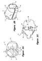
- Figure 2A is a first perspective view of a link 2 used to construct a preferred embodiment of bending neck.
- the link 2 has a socket 3.
- Two diametrically opposed channels 6 run lengthwise along the link's outer surface and a lumen 8, provides a center opening through the length of the link 2.
- One or more tabs 4 is dispersed along a rim 10 of the socket 3.
- FIG. 2C shows a sleeve 12 also used to construct the preferred bending neck.
- the sleeve 12 has a pair of diametrically opposed swivel joints 14 at one end and a pair of diametrically opposed swivel sockets 16.
- a pair of diametrically opposed finger joints 17 are formed at the end of the sleeve 12, rotationally offset from the swivel joints 14 by 90°.
- a pair of finger sockets 19 are rotationally aligned with the finger joints 17.
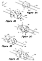
- FIG 3 shows an assembly sequence of a portion of the bending neck of the present invention.
- a series of cascaded links 2 and sleeves 12 are used in the construction of the bending neck.
- a cables 13a, 13b are shown inserted in each of the diametrically opposed channels 6 of the link 2.
- Figures 3B-C show the sleeve 12 positioned to slide over the link 2. The sleeve 12 is threaded over the end of the cables 13a and 13b and moved in the direction indicated by the arrows C. Once the sleeve 12 is in place, it is engaged and held in place by the tabs 4. The sleeve 12 captively holds the cables 13a and 13b in the channels 6 of the link 2.
- the pair of diametrically opposed swivel joints 14 at one end of the sleeve 12 is rotationally offset by 90° relative to the channels 6 and the cables 13a and 13b.
- the pair of swivel sockets 16 are adapted to receive a corresponding pair of swivel joints 14.
- a second sleeve 12' is shown pivotally attached to an adjacent sleeve 12.
- the second sleeve 12' To install the second sleeve 12', it is first threaded over the end of the cables 13a and 13b and is slid next to the adjacent sleeve 12, oriented with the swivel socket 16 of the second sleeve 12' facing the swivel joint 14 of the first sleeve 12. Initially the second sleeve 12' is offset in the Z-axis direction relative to the first sleeve 12.
- Successive sleeves 12 and links 2 are added in an identical sequence, a sleeve 12 with its swivel socket 16 adjacent to the preceding sleeve's 12 swivel joint 14, followed by the insertion of a corresponding link 2 inside the sleeve 12 with the ball 5 of one link 2 inserted into the socket 3 of the preceding link 2, until the desired number of sleeve 12 and link 2 pairs, or segments, is attained.
- the number of segments is determined by the length of the bending neck needed in a particular application.
- the bending neck 20 may be encased with a continuous elastomeric jacket (not shown) to seal the links 2, the sleeves 12, the cables 13 and other components housed within the bending neck 20 from the patient's body elements.
- the elastomeric jacket is similar to those used in the art to encase endoscopes, transesophageal ultrasound probes and other invasive medical devices designed for insertion into the body cavities.
- the smooth surface of the elastomeric jacket provides for easier insertion of the bending neck 20 into the body cavities.
- the cables 13a and 13b spanning the length of the bending neck 20 are slidably housed in separate confined spaces formed by the channels 6 in the links 2 and covered by the sleeves 12.
- the channels 6, in which the cables 13 are housed, are distinctly separated from the lumen 8 of each link 2.
- the cascade of lumens 8 of each end-to-end cascaded link 2 in the bending neck 20, establishes a conduit for any interconnections such as fiber optic cables, drive shafts, electrical conductors and system electronics needed by the particular head assembly 24.
- the isolation of the lumen 8 and the channels 6 prevents the cables 13a and 13b from rubbing against the interconnection within the conduit formed by the lumens 8, which could damage the interconnections within the conduit and reduce the reliability of the invasive medical device.
- the bending neck may be attached to an insertion tube (not shown) at the end opposite to the head assembly 24.
- FIG. 5 is a detailed view of two segments of the bending neck 20 showing articulation in the X-Y plane.
- one side in this example, the side proximal to cable 13b
- each finger joint 17 partially retreats from its corresponding finger socket 19.
- shorter side in this example, the side proximal to cable 13a
- each finger joint 17 further penetrates its corresponding finger socket 19.
- the finger joints 17 and the finger sockets 19 act as bending stops, limiting the amount of curvature of the bending neck 20 as it is articulated.
- Articulation of the dual-axis bending neck 30, is actuated by pulling one or more of the cables 23a, 23b, 23c.
- the neck 30 will bend toward the -Y-axis. If cables 23a and 23b are pulled an equal amount, neck 30 will bend toward the +Y-axis.
- the neck 30 is articulable in the +Y-axis direction with more force than in the -Y-axis direction due to the angular position of cables 23a and 23b.
- Articulation in the +Z-axis or -Z-axis directions is accomplished by pulling on either cable 26a or 26b, while allowing the other, un-pulled cable, either 26b or 26a, to slacken.
- a high bending force in a particular direction may be useful for applications in which the head assembly 24 attached to the dual-axis bending neck 30 is an ultrasound transducer.
- ultrasound transducers are pressed firmly against a patient's internal tissues to prevent unwanted reflections during ultrasound imaging.
- the bending necks described are not labor intensive to assemble and are useful with a variety of medical devices which require remote articulation and high reliability.
Abstract
A bending neck (20) for use with invasive medical devices comprises a series of pivotally hinged segments (2,12) each having a central lumen (8). The segments are positioned end-to-end, while the lumens (8) collectively provide a channel to accommodate delicate interconnections to a head assembly (24) attached to the bending neck (20). Separate from the lumen (8) are channels (6) formed in each segment, running the length of the bending neck (20) and aligned to accommodate cables (13a,13b) used to articulate the bending neck (20). The separation of the lumen (8) from the channels (6) isolates the delicate interconnections from the motion of the cables (13a,13b) as the bending neck (20) is articulated. The cables (13a,13b) and the separated lumen (8) and channels (6) form a bending neck (20) having high reliability, that is easy to assemble. The bending neck (20) may have a pair of cables (13a,13b) and articulation limited to lateral directions. Alternatively, the bending neck may have three cables (23a,23b,23c) to articulate in combinations of lateral and vertical directions.
Description
- This invention relates generally to medical devices inserted into a patient's body and particularly to a bending neck used with these invasive medical devices.
- Endoscopes, orthoscopes, ultrasound transducer probes and other invasive, imaging and therapeutic, medical devices are inserted into a patient's body. For example, transesophageal ultrasound transducer probes are inserted down a patient's oesophagus to acquire ultrasound images of the patient's heart. Endoscopes containing optical fibers may be inserted orally or nasally to view the patient's lungs or digestive tract. Orthoscopes and other devices inserted into surgical incisions are used when performing remotely controlled laser surgery. Although many types of medical devices are inserted into a patient's body, these invasive medical devices share some common attributes.
- One attribute is that most of the invasive devices are articulated, or steered, remotely. For example, once a transoesophageal ultrasound transducer probe is inserted down the oesophagus, the tip of the probe is steered remotely so that an ultrasound beam may be accurately aimed at the heart. Another attribute is that these medical device have high reliability. Since use of these medical devices may be invasive to the patient, the patient may be treated with a topical anesthetic or may be otherwise prepared, for the insertion of the medical device into the body. If the device is unreliable, the patient preparation may need to be repeated, perhaps at a high cost or at discomfort to the patient.
- One example of an invasive medical device used for imaging is the HP model number 21366A ultrasound transducer probe available from Hewlett-Packard Company. This type of probe incorporates a bending neck constructed from a series of rings each pivotally joined by a pair of aligned rivets. An ultrasound transducer is attached to the end of the bending neck and is located at the tip of the probe. Four pull cables are threaded through small holes formed in the aligned rivets inside the rings and the pull cables are retracted to articulate the bending neck. Interconnections to the ultrasound transducer are also routed through the center of the rings. As the pull cables are retracted to articulate the bending neck, there is a relative motion between the pull cables and the interconnections which may cause damage to the delicate interconnections. This type of bending neck is also labor intensive to assemble because the alignment of the small holes in the rivets is used to accommodate the pull cables. Once the small holes are precisely aligned, the pull cables are then meticulously threaded through the small holes of the rivets.
- The present invention seeks to provide an improved bending neck.
- According to an aspect of the present invention there is provided a bending neck as specified in
claim 1 or 10. - According to another aspect of the present invention there is provided a method of assembling a bending neck as specified in claim 13.
- The preferred embodiment can provide an easily assembled, reliable bending neck for use with invasive medical devices.
- The preferred bending neck comprises a series of pivotally hinged segments, each having a central lumen. The segments are positioned end-to-end, while the lumens collectively provide a shaft to accommodate delicate interconnections to a head assembly attached to the bending neck. Separate from the lumen are channels formed in each segment. The channels, combined from each segment, run the length of the bending neck and are aligned to accommodate cables used to articulate the bending neck. The separation of the lumen from the channels isolates the delicate interconnections from the motion of the cables as the bending neck is articulated.
- The cables and the segments form a bending neck having high reliability, that is easy to assemble, for use with invasive medical devices. In one embodiment, a bending neck has a pair of cables and its articulation is limited to lateral directions. In another embodiment, the bending neck has three cables and is articulable in combinations of the lateral and vertical directions.
- An embodiment of the present invention is described below, by way of example only, with reference to the accompanying drawings, in which:
- Figure 1 shows a prior art bending neck;
- Figure 2 shows perspective views of a link and a sleeve used to construct a preferred embodiment of bending neck;
- Figure 3 shows an assembly sequence of the preferred embodiment of bending neck;
- Figure 4 shows the bending neck formed by multiple link and sleeve pairs;
- Figure 5 shows a detailed view of the bending neck of Figure 4;
- Figure 6 shows a dual-axis bending neck of an alternative embodiment of bending neck; and
- Figure 7 shows a cross-section of the dual-axis bending neck of Figure 6.
- Figure 1 shows a prior
art bending neck 100 and an attachedhead assembly 104. Fourpull cables 113 are threaded through an aligned series ofrivets 102 which each have aguide hole 103 oriented to accommodate one of the pull cables. Thepull cables 113 run the length of thebending neck 100 and are each anchored at one end to thehead assembly 104. Therivets 102 also provide pivot points between a series ofrings 112 which are used to construct thebending neck 100. Electrical, fiber optic or other types of interconnections (not shown) are routed through the center of therings 112 and run the length of thebending neck 100 and to thehead assembly 104. Attached to the end of thebending neck 100, opposite thehead assembly 104, is an insertion tube (not shown). The insertion tube is long and flexible to permit deep insertion of thebending neck 100 andhead assembly 104, into the patient's body. - The
bending neck 100 and attachedhead assembly 104 are inserted into the appropriate body cavity of the patient while thehead assembly 104 is steered by articulation of thebending neck 100. The bending neck is articulated by retracting each of thepull cables 113. A steering wheel or other type of steering mechanism (not shown), attached to thepull cables 113 at the end of the insertion tube (opposite the end having thebending neck 100 attached) is used to retract thepull cables 113 in a controlled manner. This type ofbending neck 100 is incorporated in the HP model number 21366A previously mentioned. - One feature of the prior
art bending neck 100 is that thepull cables 113 and the interconnections are both located within the interior of therings 112. Thus, as thepull cables 113 articulate thebending neck 100, there is a relative motion between thepull cables 113 and the interconnections. Over time, this relative motion may cause damage to the sensitive interconnections or may negatively affect the performance of thehead assembly 104. - Figure 2A is a first perspective view of a
link 2 used to construct a preferred embodiment of bending neck. At one end, thelink 2 has asocket 3. Two diametricallyopposed channels 6 run lengthwise along the link's outer surface and alumen 8, provides a center opening through the length of thelink 2. One ormore tabs 4 is dispersed along arim 10 of thesocket 3. - Figure 2B is a second perspective view of the
link 2, showing aball 5 formed at the end of thelink 2 opposite thesocket 3. Acurved portion 9 of each of the diametricallyopposed channels 6 follows the curvature of theball 5. - Figure 2C shows a
sleeve 12 also used to construct the preferred bending neck. Thesleeve 12 has a pair of diametrically opposedswivel joints 14 at one end and a pair of diametrically opposedswivel sockets 16. A pair of diametrically opposedfinger joints 17 are formed at the end of thesleeve 12, rotationally offset from theswivel joints 14 by 90°. On the other end of thesleeve 12, a pair offinger sockets 19 are rotationally aligned with thefinger joints 17. - Figure 3 shows an assembly sequence of a portion of the bending neck of the present invention. A series of cascaded
links 2 andsleeves 12 are used in the construction of the bending neck. In Figure 3A, acables opposed channels 6 of thelink 2. Figures 3B-C show thesleeve 12 positioned to slide over thelink 2. Thesleeve 12 is threaded over the end of thecables sleeve 12 is in place, it is engaged and held in place by thetabs 4. Thesleeve 12 captively holds thecables channels 6 of thelink 2. The pair of diametrically opposed swivel joints 14 at one end of thesleeve 12 is rotationally offset by 90° relative to thechannels 6 and thecables sleeve 12, the pair ofswivel sockets 16 are adapted to receive a corresponding pair of swivel joints 14. - In Figure 3D a second sleeve 12' is shown pivotally attached to an
adjacent sleeve 12. To install the second sleeve 12', it is first threaded over the end of thecables adjacent sleeve 12, oriented with theswivel socket 16 of the second sleeve 12' facing theswivel joint 14 of thefirst sleeve 12. Initially the second sleeve 12' is offset in the Z-axis direction relative to thefirst sleeve 12. Once theswivel sockets 16 of the second sleeve 12' are aligned with the swivel joints 16 of thefirst sleeve 12, the second sleeve 12' is moved in the -Z direction to eliminate the offset, such that the swivel joints 14 are captively held by theswivel sockets 16 and thefirst sleeve 12 and the second sleeve 12' are in coaxial alignment. - As shown in Figure 3E, a second link 2' is inserted in the second sleeve 12' and also engaged by
tabs 4. Although the second link 2' is not visible in Figures 3D and 3E, theball 5 of the second link 2' is inserted into thesocket 3 of thefirst link 2. As with thefirst link 2, the second link 2' also has the cables 13 guided through thechannels 6 and the cables 13 are captively held within thechannels 6 by thesleeves 12.Successive sleeves 12 andlinks 2 are added in an identical sequence, asleeve 12 with itsswivel socket 16 adjacent to the preceding sleeve's 12 swivel joint 14, followed by the insertion of acorresponding link 2 inside thesleeve 12 with theball 5 of onelink 2 inserted into thesocket 3 of thepreceding link 2, until the desired number ofsleeve 12 andlink 2 pairs, or segments, is attained. The number of segments is determined by the length of the bending neck needed in a particular application. - Figure 4A shows
preferred bending neck 20, formed by multiple segments, orlink 2 andsleeve 12 pairs. Only thetabs 4 of thelinks 2 are visible, as the links are internal to thesleeves 12. The number of segments, may vary dependent on the length of eachlink 2 andsleeve 12, and on the overall length of the bendingneck 20 desired for a particular application. Ahead assembly 24, shown in Figure 4B, is attached to an end of the bendingneck 20 and eachcable cable 13a orcable 13b, the bendingneck 20 articulates in the +Y-axis or the -Y axis direction corresponding to whichcable cable 13a is pulled in the direction indicated by arrow A, the bendingneck 20 curves in the +Y-axis direction. Similarly, whencable 13b is pulled in the direction indicated by arrow B, the bendingneck 20 curves in the -Y-axis direction. Motion of the bendingneck 20, as thecables swivel sockets 16. - The bending
neck 20 may be encased with a continuous elastomeric jacket (not shown) to seal thelinks 2, thesleeves 12, the cables 13 and other components housed within the bendingneck 20 from the patient's body elements. The elastomeric jacket is similar to those used in the art to encase endoscopes, transesophageal ultrasound probes and other invasive medical devices designed for insertion into the body cavities. The smooth surface of the elastomeric jacket provides for easier insertion of the bendingneck 20 into the body cavities. Thecables neck 20 are slidably housed in separate confined spaces formed by thechannels 6 in thelinks 2 and covered by thesleeves 12. Thechannels 6, in which the cables 13 are housed, are distinctly separated from thelumen 8 of eachlink 2. The cascade oflumens 8 of each end-to-end cascadedlink 2 in the bendingneck 20, establishes a conduit for any interconnections such as fiber optic cables, drive shafts, electrical conductors and system electronics needed by theparticular head assembly 24. The isolation of thelumen 8 and thechannels 6 prevents thecables lumens 8, which could damage the interconnections within the conduit and reduce the reliability of the invasive medical device. The bending neck may be attached to an insertion tube (not shown) at the end opposite to thehead assembly 24. - Figure 5 is a detailed view of two segments of the bending
neck 20 showing articulation in the X-Y plane. As the bendingneck 20 is articulated, one side (in this example, the side proximal tocable 13b) is elongated relative to the other side. On the elongated side, each finger joint 17 partially retreats from itscorresponding finger socket 19. On the other, shorter side (in this example, the side proximal tocable 13a) of the articulated bending neck 20 (not visible in Figure 5), each finger joint 17 further penetrates itscorresponding finger socket 19. The finger joints 17 and thefinger sockets 19 act as bending stops, limiting the amount of curvature of the bendingneck 20 as it is articulated. The length of the finger joints and the depth of the finger sockets define the curvature of the bendingneck 20 in the X-Y plane. There may be one or more finger joints 17 andfinger sockets 19 on each side of the bendingneck 20. The finger joints 17 in thefinger sockets 19, also prevent the elastomeric jacket from becoming pinched byadjacent sleeves 12 as the bendingneck 20 is articulated. - Pivoting of the
sleeves 12 in the +Y-axis and the -Y-axis directions is provided by the pivotal action of each swivel joint 14 within itscorresponding swivel socket 16. Pivoting of thelinks 2 inside thesleeves 12 is provided by the pivotal action of theball 5 in thesocket 3 of theadjacent links 2. Rotational spinning of thesleeves 12 about the X-axis, or lengthwise direction, of the bendingneck 20 is prevented by engagement of thetabs 4 of thelinks 2 with thesleeves 12. Rotational spinning of thelinks 2 andsleeves 12 is avoided to prevent binding of the bendingneck 20 as it is articulated. If rotational spinning did occur, it may cause loss of control of the bendingneck 20 articulation or it may damage the delicate interconnections within the conduit. Articulation of the dual-axis bending neck 30 may be controlled via a joystick, steering wheel or other device attached to thepull cables - Figure 6 shows a dual-
axis bending neck 30. In this alternative embodiment, the swivel joint 14 andcorresponding swivel socket 16 ofadjacent sleeves 12 alternate in rotational offsets of 90° about the X-axis, or lengthwise axis, of the dualaxis bending neck 30. Offsetsleeves 12b provide for articulation in the +Y-axis and -Y-axis directions while the on-axis sleeves 12a provide for articulation in the Z-axis and -Z-axis direction. As a result, the dual-axis bending neck 30 may be articulated in any direction within the Y-Z plane. - Figure 7 shows a cross-sectional view of a the dual-
axis bending neck 30, orneck 30. Threechannels link 2 to house correspondingcables axis bending neck 30. Thecables channels sleeves lumen 8 of each of the cascadedlinks 2 collectively form a conduit running lengthwise through the dual-axis bending neck 30. Thechannels third channel 26c, is positioned along the -Y-axis. Articulation of the dual-axis bending neck 30, is actuated by pulling one or more of thecables cable 23c within thechannel 26c is pulled, theneck 30 will bend toward the -Y-axis. Ifcables neck 30 will bend toward the +Y-axis. In this embodiment, theneck 30 is articulable in the +Y-axis direction with more force than in the -Y-axis direction due to the angular position ofcables cable - A greater number of channels may also be formed in the
links 2 and the channels may be formed at various rotational positions about thelink 2. However, in the second embodiment, the rotational positions of thechannels axis bending neck 30 is articulated in the +Y-axis direction than in the -Y-axis direction. For example, with a force F applied to each ofcables neck 30 is 2*F*Cos 45°. This bending force is greater than 2*F*Cos 60° as it would be for a force F applied to two cables, were the cables and channels equi-spaced rotationally about thelink 2. A high bending force in a particular direction may be useful for applications in which thehead assembly 24 attached to the dual-axis bending neck 30 is an ultrasound transducer. For example, ultrasound transducers are pressed firmly against a patient's internal tissues to prevent unwanted reflections during ultrasound imaging. - The bending necks described are not labor intensive to assemble and are useful with a variety of medical devices which require remote articulation and high reliability.
- The disclosures in United States patent application no. 08/576,940, from which this application claims priority, and in the abstract accompanying this application are incorporated herein by reference.
Claims (13)
- A bending neck for accommodating a head assembly (24) of an invasive medical device, articulable by retractable cables (13a,13b) anchored to the head assembly (24), the bending neck(20) comprising:a series of pivotally attached segments (2,12);a center conduit provided through the center of the series, for housing interconnections to the head assembly (24);a plurality of channels (6), isolated from the center conduit (8), for housing retractable cables (13a,13b).
- A bending neck as in claim 1, wherein each of the pivotally attached segments (2,12) comprises a lumen (8), the lumens (8) collectively forming the central conduit.
- A bending neck as in claim 1 or 2, wherein the channels (6) are parallel to the center conduit.
- A bending neck as in claim 1, 2 or 3, wherein each segment (2,12) has a substantially round cross-section and wherein the channels (6) are disposed around the center conduit.
- A bending neck as in any preceding claim, wherein the pivotally attached segments (2,12) provide articulation of the bending neck in a plane containing a pair of the channels (6).
- A bending neck as in any preceding claim, wherein each segment comprises:a pair of swivel joints (14), diametrically opposed, positioned at a first end of each of the segments (2,12) and rotationally offset from at least a pair of the channels (6); anda pair of swivel sockets (16), diametrically opposed, positioned at a second end of each of the segments such that the pair of swivel sockets (16) of each segment can receive the pair of swivel joints (14) of an adjacent segment (2,12) of the series to provide pivotal attachment of segments (2,12).
- A bending neck as in claim 6, wherein the pair of swivel joints (14) is rotationally offset by substantially 90° relative to the pair of swivel sockets (16).
- A bending neck as in any preceding claim, wherein a pair of channels (26a, 26b) is disposed about the center conduit in a first half of the cross-section of each segment and a third channel is disposed about the center conduit in a second half of the cross-section.
- A bending neck as in claim 8, wherein a first channel (26a) of the pair of channels is rotationally offset by at least 90° from the second channel (26b) of the pair of channels and the third channel (26c) is rotationally offset from each channel of the pair by at least 90°.
- A bending neck (20) for a remotely controlled head (24) assembly used in invasive medical procedures, comprising:a series of cylindrical links (2,12) including a concave socket (3) at a first end and a convex ball (5) at the second end, the convex ball (5) of each link being adapted to engage the concave socket (3) of an adjacent link in the series;a series of tubular sleeves (12) for encircling the links, each sleeve (12) corresponding to a link in the series;a plurality of channels (6) formed in each link, encased by the tubular sleeve (12), the channels (6) spanning the length of the links;a plurality of tabs (4), at least one tab (4) of the plurality of tabs protruding from each link of the series, engaging the tubular sleeve (12);a pair of swivel joints (14), diametrically opposed, positioned at a first end of each of the sleeves (12);a pair of swivel sockets (16), diametrically opposed, positioned at a second end of each of the sleeves adapted to receive the pair of swivel joints (14);a central lumen (8) formed within each of the links, the lumens (8) of the links collectively forming a center conduit, through the length of the bending neck (20); anda plurality of retractable cables (13a,13b), anchored to the head assembly (24), each cable (13a,13b) threaded through a corresponding channel (6), and wherein the bending neck is articulated by retraction of at least one the retractable cables (13a,13b).
- A bending neck as in claim 10, wherein each tubular sleeve (12) comprises at least one pair of slidable finger joints (17) and at least one pair of corresponding finger sockets (19), the depth of penetration of the slidable finger joints (17) in the corresponding finger sockets (19) determining the maximum articulation of the bending neck.
- A bending neck as in claim 10 or 11, wherein the head assembly (24) comprises an ultrasound transducer and wherein the center conduit contains flexible electronic interconnections connected to the ultrasound transducer.
- A method of assembling a bending neck comprising a series of pivotally hinged segments, each segment comprising an inner link (2) and an outer sleeve (12), a plurality of channels (6) formed in the inner link (2) and encased by the outer sleeve (12), the outer sleeve (12) comprising a pair of swivel joints (14) at one end and a pair of swivel sockets (16) at the other end, the bending neck (20) articulable by a plurality of retractable cables (13a,13b), the method comprising the steps of:inserting the plurality of cables (13a,13b) in the plurality of channels of a link (2);threading a first sleeve (12a) over the end of the plurality of cables (13a,13b);sliding the sleeve over the link (2);threading a second sleeve (12b) over the end of the plurality of cables such that the pair of swivel joints (14) of the second sleeve (12b) is oriented towards the pair of swivel sockets (16) of the first sleeve (12a);offsetting the second sleeve (12b) from the first sleeve (12a) in a direction substantially perpendicular to the cables (13a,13b);aligning the swivel joints (14) of the second sleeve (12b) with the swivel sockets (16) of the first sleeve (12a);engaging the swivel joints (14) with the swivel sockets (16) by eliminating the offset; andinserting a second link (2) in the second sleeve (12).
Applications Claiming Priority (2)
| Application Number | Priority Date | Filing Date | Title |
|---|---|---|---|
| US576940 | 1995-12-22 | ||
| US08/576,940 US5749828A (en) | 1995-12-22 | 1995-12-22 | Bending neck for use with invasive medical devices |
Publications (1)
| Publication Number | Publication Date |
|---|---|
| EP0782836A1 true EP0782836A1 (en) | 1997-07-09 |
Family
ID=24306629
Family Applications (1)
| Application Number | Title | Priority Date | Filing Date |
|---|---|---|---|
| EP96308887A Withdrawn EP0782836A1 (en) | 1995-12-22 | 1996-12-06 | Catheter with bending control |
Country Status (3)
| Country | Link |
|---|---|
| US (1) | US5749828A (en) |
| EP (1) | EP0782836A1 (en) |
| JP (1) | JPH09182737A (en) |
Cited By (33)
| Publication number | Priority date | Publication date | Assignee | Title |
|---|---|---|---|---|
| US6273876B1 (en) | 1997-12-05 | 2001-08-14 | Intratherapeutics, Inc. | Catheter segments having circumferential supports with axial projection |
| WO2005023101A1 (en) | 2003-09-05 | 2005-03-17 | Olympus Corporation | Endoscope |
| EP1604607A1 (en) * | 2004-06-08 | 2005-12-14 | Henke-Sass, Wolf GmbH | Flexible section of an insertion tube of an endoscope and method of manufacturing thereof |
| WO2013086071A1 (en) * | 2011-12-07 | 2013-06-13 | Symmetry Medical New Bedford, Inc. | System and method for an articulating shaft |
| WO2013128860A1 (en) * | 2012-02-28 | 2013-09-06 | Terumo Kabushiki Kaisha | Flexible tube for medical instrument and medical instrument |
| WO2017014624A1 (en) | 2015-07-17 | 2017-01-26 | Fortimedix Surgical B.V. | Steerable instrument comprising a cylindrical diameter adaption section |
| WO2017082720A1 (en) | 2015-11-13 | 2017-05-18 | Fortimedix Surgical B.V. | Elongated steerable tubular body and steerable instrument comprising the same |
| WO2017213491A1 (en) | 2016-06-06 | 2017-12-14 | Fortimedix Surgical B.V. | Steerable instrument comprising a cilindrical diameter adaptation section |
| US10188392B2 (en) | 2014-12-19 | 2019-01-29 | Abbott Cardiovascular Systems, Inc. | Grasping for tissue repair |
| US10238495B2 (en) | 2015-10-09 | 2019-03-26 | Evalve, Inc. | Delivery catheter handle and methods of use |
| US10238494B2 (en) | 2015-06-29 | 2019-03-26 | Evalve, Inc. | Self-aligning radiopaque ring |
| US10314586B2 (en) | 2016-12-13 | 2019-06-11 | Evalve, Inc. | Rotatable device and method for fixing tricuspid valve tissue |
| EP1624792B1 (en) * | 2003-05-19 | 2019-06-19 | Evalve, Inc. | Articulatable access sheath |
| US10363138B2 (en) | 2016-11-09 | 2019-07-30 | Evalve, Inc. | Devices for adjusting the curvature of cardiac valve structures |
| US10376673B2 (en) | 2015-06-19 | 2019-08-13 | Evalve, Inc. | Catheter guiding system and methods |
| US10390943B2 (en) | 2014-03-17 | 2019-08-27 | Evalve, Inc. | Double orifice device for transcatheter mitral valve replacement |
| US10398553B2 (en) | 2016-11-11 | 2019-09-03 | Evalve, Inc. | Opposing disk device for grasping cardiac valve tissue |
| US10413408B2 (en) | 2015-08-06 | 2019-09-17 | Evalve, Inc. | Delivery catheter systems, methods, and devices |
| US10426616B2 (en) | 2016-11-17 | 2019-10-01 | Evalve, Inc. | Cardiac implant delivery system |
| US10524912B2 (en) | 2015-04-02 | 2020-01-07 | Abbott Cardiovascular Systems, Inc. | Tissue fixation devices and methods |
| EP3593700A1 (en) | 2014-12-05 | 2020-01-15 | Fortimedix Surgical B.V. | Method for manufacturing a steerable instrument and such steerable instrument |
| US10624618B2 (en) | 2001-06-27 | 2020-04-21 | Evalve, Inc. | Methods and devices for capturing and fixing leaflets in valve repair |
| US10631871B2 (en) | 2003-05-19 | 2020-04-28 | Evalve, Inc. | Fixation devices, systems and methods for engaging tissue |
| US10667804B2 (en) | 2014-03-17 | 2020-06-02 | Evalve, Inc. | Mitral valve fixation device removal devices and methods |
| US10667815B2 (en) | 2015-07-21 | 2020-06-02 | Evalve, Inc. | Tissue grasping devices and related methods |
| US10736632B2 (en) | 2016-07-06 | 2020-08-11 | Evalve, Inc. | Methods and devices for valve clip excision |
| US10743876B2 (en) | 2011-09-13 | 2020-08-18 | Abbott Cardiovascular Systems Inc. | System for fixation of leaflets of a heart valve |
| US10779837B2 (en) | 2016-12-08 | 2020-09-22 | Evalve, Inc. | Adjustable arm device for grasping tissues |
| WO2020234328A1 (en) * | 2019-05-21 | 2020-11-26 | Koninklijke Philips N.V. | Pull-cable management for steerable catheter |
| US11065119B2 (en) | 2017-05-12 | 2021-07-20 | Evalve, Inc. | Long arm valve repair clip |
| US11071564B2 (en) | 2016-10-05 | 2021-07-27 | Evalve, Inc. | Cardiac valve cutting device |
| CN113243947A (en) * | 2021-05-19 | 2021-08-13 | 中国科学院自动化研究所 | Bronchus intervention continuum robot for small nodules of lung |
| US11957358B2 (en) | 2020-09-21 | 2024-04-16 | Evalve, Inc. | Adjustable arm device for grasping tissues |
Families Citing this family (163)
| Publication number | Priority date | Publication date | Assignee | Title |
|---|---|---|---|---|
| FR2768324B1 (en) | 1997-09-12 | 1999-12-10 | Jacques Seguin | SURGICAL INSTRUMENT FOR PERCUTANEOUSLY FIXING TWO AREAS OF SOFT TISSUE, NORMALLY MUTUALLY REMOTE, TO ONE ANOTHER |
| US5976075A (en) * | 1997-12-15 | 1999-11-02 | University Of Massachusetts | Endoscope deployment apparatus |
| CA2323540C (en) | 1998-03-20 | 2004-12-07 | Scimed Life Systems, Inc. | Endoscopic suture systems |
| US6179776B1 (en) | 1999-03-12 | 2001-01-30 | Scimed Life Systems, Inc. | Controllable endoscopic sheath apparatus and related method of use |
| US8216256B2 (en) * | 1999-04-09 | 2012-07-10 | Evalve, Inc. | Detachment mechanism for implantable fixation devices |
| US7226467B2 (en) | 1999-04-09 | 2007-06-05 | Evalve, Inc. | Fixation device delivery catheter, systems and methods of use |
| CA2620783C (en) | 1999-04-09 | 2011-04-05 | Evalve, Inc. | Methods and apparatus for cardiac valve repair |
| US7604646B2 (en) | 1999-04-09 | 2009-10-20 | Evalve, Inc. | Locking mechanisms for fixation devices and methods of engaging tissue |
| US7811296B2 (en) | 1999-04-09 | 2010-10-12 | Evalve, Inc. | Fixation devices for variation in engagement of tissue |
| US6491626B1 (en) * | 1999-04-16 | 2002-12-10 | Nuvasive | Articulation systems for positioning minimally invasive surgical tools |
| US6482149B1 (en) * | 1999-05-12 | 2002-11-19 | Fuji Photo Optical Co., Ltd. | Curved part of endoscope |
| US6200306B1 (en) * | 1999-05-26 | 2001-03-13 | Sulzer Carbomedics Inc. | Bend clip for flexible rotator |
| US7955340B2 (en) * | 1999-06-25 | 2011-06-07 | Usgi Medical, Inc. | Apparatus and methods for forming and securing gastrointestinal tissue folds |
| US7416554B2 (en) | 2002-12-11 | 2008-08-26 | Usgi Medical Inc | Apparatus and methods for forming and securing gastrointestinal tissue folds |
| US20040122456A1 (en) * | 2002-12-11 | 2004-06-24 | Saadat Vahid C. | Methods and apparatus for gastric reduction |
| US7637905B2 (en) | 2003-01-15 | 2009-12-29 | Usgi Medical, Inc. | Endoluminal tool deployment system |
| US6561398B1 (en) * | 1999-11-23 | 2003-05-13 | Yakima Products, Inc. | Rack assembly for a vehicle |
| US6364828B1 (en) | 2000-01-06 | 2002-04-02 | Hubert K. Yeung | Elongated flexible inspection neck |
| US6974411B2 (en) * | 2000-04-03 | 2005-12-13 | Neoguide Systems, Inc. | Endoscope with single step guiding apparatus |
| US8888688B2 (en) | 2000-04-03 | 2014-11-18 | Intuitive Surgical Operations, Inc. | Connector device for a controllable instrument |
| US6800056B2 (en) | 2000-04-03 | 2004-10-05 | Neoguide Systems, Inc. | Endoscope with guiding apparatus |
| US6468203B2 (en) | 2000-04-03 | 2002-10-22 | Neoguide Systems, Inc. | Steerable endoscope and improved method of insertion |
| US6610007B2 (en) * | 2000-04-03 | 2003-08-26 | Neoguide Systems, Inc. | Steerable segmented endoscope and method of insertion |
| US6837846B2 (en) * | 2000-04-03 | 2005-01-04 | Neo Guide Systems, Inc. | Endoscope having a guide tube |
| US8517923B2 (en) | 2000-04-03 | 2013-08-27 | Intuitive Surgical Operations, Inc. | Apparatus and methods for facilitating treatment of tissue via improved delivery of energy based and non-energy based modalities |
| US6858005B2 (en) | 2000-04-03 | 2005-02-22 | Neo Guide Systems, Inc. | Tendon-driven endoscope and methods of insertion |
| US6743239B1 (en) | 2000-05-25 | 2004-06-01 | St. Jude Medical, Inc. | Devices with a bendable tip for medical procedures |
| JP2002078674A (en) * | 2000-09-08 | 2002-03-19 | Fuji Photo Optical Co Ltd | Curved surface structure of endoscope |
| CN1764416A (en) | 2002-01-09 | 2006-04-26 | 新引导系统公司 | Apparatus and method for endoscopic colectomy |
| CN1617687A (en) * | 2002-01-09 | 2005-05-18 | 新引导系统公司 | Apparatus and method for spectroscopic examination of the colon |
| US7048754B2 (en) | 2002-03-01 | 2006-05-23 | Evalve, Inc. | Suture fasteners and methods of use |
| US7041052B2 (en) | 2002-06-13 | 2006-05-09 | Usgi Medical Inc. | Shape lockable apparatus and method for advancing an instrument through unsupported anatomy |
| US20060058582A1 (en) * | 2002-06-13 | 2006-03-16 | Usgi Medical Inc. | Disposable shapelocking system |
| US20050137454A1 (en) * | 2002-06-13 | 2005-06-23 | Usgi Medical Corp. | Shape lockable apparatus and method for advancing an instrument through unsupported anatomy |
| US6783491B2 (en) * | 2002-06-13 | 2004-08-31 | Vahid Saadat | Shape lockable apparatus and method for advancing an instrument through unsupported anatomy |
| US6921363B2 (en) | 2002-10-03 | 2005-07-26 | Koninklijke Philips Electronics N.V. | Transesophageal endoscope with improved bite-through protection |
| US7942884B2 (en) * | 2002-12-11 | 2011-05-17 | Usgi Medical, Inc. | Methods for reduction of a gastric lumen |
| US7942898B2 (en) * | 2002-12-11 | 2011-05-17 | Usgi Medical, Inc. | Delivery systems and methods for gastric reduction |
| US20040186350A1 (en) * | 2003-01-13 | 2004-09-23 | Usgi Medical Corp. | Apparatus and methods for guiding an endoscope via a rigidizable wire guide |
| US20040249367A1 (en) * | 2003-01-15 | 2004-12-09 | Usgi Medical Corp. | Endoluminal tool deployment system |
| US8882657B2 (en) | 2003-03-07 | 2014-11-11 | Intuitive Surgical Operations, Inc. | Instrument having radio frequency identification systems and methods for use |
| US8118732B2 (en) | 2003-04-01 | 2012-02-21 | Boston Scientific Scimed, Inc. | Force feedback control system for video endoscope |
| US7591783B2 (en) | 2003-04-01 | 2009-09-22 | Boston Scientific Scimed, Inc. | Articulation joint for video endoscope |
| US20040199052A1 (en) * | 2003-04-01 | 2004-10-07 | Scimed Life Systems, Inc. | Endoscopic imaging system |
| US20050245789A1 (en) | 2003-04-01 | 2005-11-03 | Boston Scientific Scimed, Inc. | Fluid manifold for endoscope system |
| US7578786B2 (en) * | 2003-04-01 | 2009-08-25 | Boston Scientific Scimed, Inc. | Video endoscope |
| GB0324173D0 (en) * | 2003-10-15 | 2003-11-19 | Anson Medical Ltd | Flexible delivery system |
| JP4540328B2 (en) * | 2003-11-19 | 2010-09-08 | カール事務器株式会社 | Multi-function drilling device |
| US20050131457A1 (en) * | 2003-12-15 | 2005-06-16 | Ethicon, Inc. | Variable stiffness shaft |
| US20050171467A1 (en) * | 2004-01-30 | 2005-08-04 | Jaime Landman | Multiple function surgical device |
| US7703459B2 (en) | 2004-03-09 | 2010-04-27 | Usgi Medical, Inc. | Apparatus and methods for mapping out endoluminal gastrointestinal surgery |
| US7918869B2 (en) | 2004-05-07 | 2011-04-05 | Usgi Medical, Inc. | Methods and apparatus for performing endoluminal gastroplasty |
| US7670284B2 (en) * | 2004-08-31 | 2010-03-02 | Surgical Solutions Llc | Medical device with articulating shaft |
| IL164260A0 (en) * | 2004-09-23 | 2005-12-18 | Medigus Ltd | An improved articulation section |
| US8052592B2 (en) | 2005-09-27 | 2011-11-08 | Evalve, Inc. | Methods and devices for tissue grasping and assessment |
| CA2748617C (en) | 2004-09-27 | 2014-09-23 | Evalve, Inc. | Methods and devices for tissue grasping and assessment |
| US20060156851A1 (en) * | 2004-12-02 | 2006-07-20 | Jacobsen Stephen C | Mechanical serpentine device |
| US20060178562A1 (en) * | 2005-02-10 | 2006-08-10 | Usgi Medical Inc. | Apparatus and methods for obtaining endoluminal access with a steerable guide having a variable pivot |
| US7618413B2 (en) * | 2005-06-22 | 2009-11-17 | Boston Scientific Scimed, Inc. | Medical device control system |
| US8052597B2 (en) * | 2005-08-30 | 2011-11-08 | Boston Scientific Scimed, Inc. | Method for forming an endoscope articulation joint |
| WO2007034664A1 (en) * | 2005-09-22 | 2007-03-29 | Olympus Corporation | Endoscope insertion part |
| EP3788944B1 (en) | 2005-11-22 | 2024-02-28 | Intuitive Surgical Operations, Inc. | System for determining the shape of a bendable instrument |
| JP2009517608A (en) | 2005-11-23 | 2009-04-30 | ネオガイド システムズ, インコーポレイテッド | Non-metallic multi-strand control cable for steerable devices |
| US20090242115A1 (en) * | 2006-01-23 | 2009-10-01 | Olympus Corporation | Method of manufacturing insertion portion of endoscope |
| US8726909B2 (en) | 2006-01-27 | 2014-05-20 | Usgi Medical, Inc. | Methods and apparatus for revision of obesity procedures |
| US8211114B2 (en) * | 2006-04-24 | 2012-07-03 | Ethicon Endo-Surgery, Inc. | Medical instrument having a medical snare |
| US20070249908A1 (en) * | 2006-04-24 | 2007-10-25 | Ifung Lu | Medical cannula and medical cannula system |
| US20070250012A1 (en) * | 2006-04-24 | 2007-10-25 | Ifung Lu | Medical instrument having a medical needle-knife |
| US9138250B2 (en) * | 2006-04-24 | 2015-09-22 | Ethicon Endo-Surgery, Inc. | Medical instrument handle and medical instrument having a handle |
| US7837620B2 (en) * | 2006-04-25 | 2010-11-23 | Ethicon Endo-Surgery, Inc. | Medical tubular assembly |
| US7927327B2 (en) * | 2006-04-25 | 2011-04-19 | Ethicon Endo-Surgery, Inc. | Medical instrument having an articulatable end effector |
| US20070255312A1 (en) * | 2006-05-01 | 2007-11-01 | Ifung Lu | Medical instrument having an end-effector-associated member |
| US7758593B2 (en) * | 2006-05-04 | 2010-07-20 | Ethicon Endo-Surgery, Inc. | Medical instrument handle and medical instrument having same |
| US7959642B2 (en) * | 2006-05-16 | 2011-06-14 | Ethicon Endo-Surgery, Inc. | Medical instrument having a needle knife |
| US20070270639A1 (en) * | 2006-05-17 | 2007-11-22 | Long Gary L | Medical instrument having a catheter and having a catheter accessory device and method for using |
| US7892166B2 (en) | 2006-05-18 | 2011-02-22 | Ethicon Endo-Surgery, Inc. | Medical instrument including a catheter having a catheter stiffener and method for using |
| WO2007137208A2 (en) | 2006-05-19 | 2007-11-29 | Neoguide Systems, Inc. | Methods and apparatus for displaying three-dimensional orientation of a steerable distal tip of an endoscope |
| CN101528111B (en) * | 2006-08-14 | 2012-04-04 | 卡迪欧机器人技术股份有限公司 | Steerable multi-linked device having multiple working ports |
| US8475453B2 (en) | 2006-10-06 | 2013-07-02 | Covidien Lp | Endoscopic vessel sealer and divider having a flexible articulating shaft |
| JP5399910B2 (en) * | 2006-11-13 | 2014-01-29 | レイセオン カンパニー | Versatile endless track for lightweight mobile robot |
| US8185241B2 (en) * | 2006-11-13 | 2012-05-22 | Raytheon Company | Tracked robotic crawler having a moveable arm |
| EP2258608A1 (en) | 2006-11-13 | 2010-12-08 | Raytheon Sarcos LLC | Conformable track assembly for a robotic crawler |
| US7845440B2 (en) * | 2006-11-13 | 2010-12-07 | Raytheon Sarcos, Llc | Serpentine robotic crawler |
| US20080215185A1 (en) * | 2006-11-13 | 2008-09-04 | Jacobsen Stephen C | Unmanned ground robotic vehicle having an alternatively extendible and retractable sensing appendage |
| US8715270B2 (en) | 2006-12-01 | 2014-05-06 | Boston Scientific Scimed, Inc. | Multi-part instrument systems and methods |
| ES2526061T3 (en) | 2007-02-27 | 2015-01-05 | Carnegie Mellon University | System for releasably fixing a disposable device to a durable device |
| DE502007001349D1 (en) * | 2007-04-04 | 2009-10-01 | Wolf Gmbh Richard | Endoscopic instrument |
| WO2008137953A1 (en) | 2007-05-07 | 2008-11-13 | Raytheon Sarcos, Llc | Method for manufacturing a complex structure |
| US20080281468A1 (en) * | 2007-05-08 | 2008-11-13 | Raytheon Sarcos, Llc | Variable primitive mapping for a robotic crawler |
| US9533122B2 (en) | 2007-05-18 | 2017-01-03 | Boston Scientific Scimed, Inc. | Catheter drive system with control handle rotatable about two axes separated from housing by shaft |
| US20090025988A1 (en) * | 2007-07-10 | 2009-01-29 | Jacobsen Stephen C | Serpentine Robotic Crawler Having A Continuous Track |
| CN101784435B (en) * | 2007-07-10 | 2013-08-28 | 雷神萨科斯公司 | Modular robotic crawler |
| US9220398B2 (en) | 2007-10-11 | 2015-12-29 | Intuitive Surgical Operations, Inc. | System for managing Bowden cables in articulating instruments |
| KR101707924B1 (en) * | 2008-02-06 | 2017-02-17 | 인튜어티브 서지컬 오퍼레이션즈 인코포레이티드 | A segmented instrument having braking capabilities |
| US8182418B2 (en) | 2008-02-25 | 2012-05-22 | Intuitive Surgical Operations, Inc. | Systems and methods for articulating an elongate body |
| US8246575B2 (en) * | 2008-02-26 | 2012-08-21 | Tyco Healthcare Group Lp | Flexible hollow spine with locking feature and manipulation structure |
| US8628545B2 (en) * | 2008-06-13 | 2014-01-14 | Covidien Lp | Endoscopic stitching devices |
| US20110040308A1 (en) | 2008-06-13 | 2011-02-17 | Ramiro Cabrera | Endoscopic Stitching Devices |
| JP5559785B2 (en) | 2008-07-18 | 2014-07-23 | ボストン サイエンティフィック サイムド,インコーポレイテッド | Guided endoscope |
| CA2736248C (en) | 2008-09-05 | 2017-12-05 | Carnegie Mellon University | Multi-linked endoscopic device with spherical distal assembly |
| US8392036B2 (en) | 2009-01-08 | 2013-03-05 | Raytheon Company | Point and go navigation system and method |
| US7918376B1 (en) | 2009-03-09 | 2011-04-05 | Cardica, Inc. | Articulated surgical instrument |
| FR2943906B1 (en) | 2009-04-03 | 2013-03-22 | Univ Pierre Et Marie Curie Paris 6 | SURGICAL INSTRUMENT. |
| FR2943907B1 (en) | 2009-04-03 | 2012-08-03 | Univ Pierre Et Marie Curie Paris 6 | SURGICAL INSTRUMENT. |
| DE102009017175B4 (en) * | 2009-04-09 | 2011-05-05 | Richard Wolf Gmbh | Method for producing a bendable tube |
| US9289208B1 (en) | 2009-05-05 | 2016-03-22 | Cardica, Inc. | Articulation insert for surgical instrument |
| US8096457B1 (en) | 2009-05-05 | 2012-01-17 | Cardica, Inc. | Articulation mechanisms for surgical instrument |
| US8317555B2 (en) * | 2009-06-11 | 2012-11-27 | Raytheon Company | Amphibious robotic crawler |
| US8935014B2 (en) * | 2009-06-11 | 2015-01-13 | Sarcos, Lc | Method and system for deploying a surveillance network |
| WO2011005335A1 (en) * | 2009-07-10 | 2011-01-13 | Tyco Healthcare Group Lp | Shaft constructions for medical devices with an articulating tip |
| US20110022078A1 (en) | 2009-07-23 | 2011-01-27 | Cameron Dale Hinman | Articulating mechanism |
| US20110034771A1 (en) * | 2009-08-07 | 2011-02-10 | Gyrus Acmi, Inc. | Endoscope resilient deflection section frame |
| WO2011127137A1 (en) | 2010-04-06 | 2011-10-13 | Pavel Menn | Articulating steerable clip applier for laparoscopic procedures |
| US9795765B2 (en) | 2010-04-09 | 2017-10-24 | St. Jude Medical International Holding S.À R.L. | Variable stiffness steering mechanism for catheters |
| US8419767B2 (en) | 2010-05-04 | 2013-04-16 | Mustafa H. Al-Qbandi | Steerable atrial septal occluder implantation device with flexible neck |
| US8562610B2 (en) * | 2010-07-13 | 2013-10-22 | Warsaw Orthopedic, Inc. | Compliant device and method for cutting an intervertebral disc |
| EP2670288B1 (en) | 2011-01-31 | 2017-05-31 | Boston Scientific Scimed, Inc. | Articulation section with locking |
| US20120232567A1 (en) * | 2011-03-10 | 2012-09-13 | Boston Scientific Scimed, Inc. | Flexible suturing instrument |
| US9038880B1 (en) * | 2011-04-25 | 2015-05-26 | Cardica, Inc. | Articulated surgical instrument |
| US9566048B1 (en) | 2011-04-26 | 2017-02-14 | Cardica, Inc. | Surgical instrument with discrete cammed articulation |
| US9474527B1 (en) | 2011-04-26 | 2016-10-25 | Bryan D. Knodel | Surgical instrument with discrete articulation |
| JP5788239B2 (en) * | 2011-06-23 | 2015-09-30 | オリンパス株式会社 | Orbit forming device |
| US9119639B2 (en) * | 2011-08-09 | 2015-09-01 | DePuy Synthes Products, Inc. | Articulated cavity creator |
| US20140296630A1 (en) * | 2011-08-30 | 2014-10-02 | Paul A. Zwirkoski | Medical Osteotome Assembly |
| EP2581031A1 (en) * | 2011-10-13 | 2013-04-17 | Johann Klaffenböck | Bending device |
| EP2785497B1 (en) * | 2011-12-02 | 2022-10-26 | Boston Scientific Scimed, Inc. | Positioning device and articulation assembly for remote positioning of a tool |
| US9956042B2 (en) | 2012-01-13 | 2018-05-01 | Vanderbilt University | Systems and methods for robot-assisted transurethral exploration and intervention |
| US8419720B1 (en) | 2012-02-07 | 2013-04-16 | National Advanced Endoscopy Devices, Incorporated | Flexible laparoscopic device |
| JP5480453B2 (en) * | 2012-02-20 | 2014-04-23 | オリンパスメディカルシステムズ株式会社 | Node ring, endoscope bending tube, endoscope, method for manufacturing node ring for endoscope bending tube |
| US9033975B2 (en) * | 2012-02-29 | 2015-05-19 | Boston Scientific Scimed, Inc. | Electrosurgical device and system |
| US9211134B2 (en) | 2012-04-09 | 2015-12-15 | Carefusion 2200, Inc. | Wrist assembly for articulating laparoscopic surgical instruments |
| US9265514B2 (en) | 2012-04-17 | 2016-02-23 | Miteas Ltd. | Manipulator for grasping tissue |
| WO2013158974A1 (en) | 2012-04-20 | 2013-10-24 | Vanderbilt University | Dexterous wrists for surgical intervention |
| US9539726B2 (en) | 2012-04-20 | 2017-01-10 | Vanderbilt University | Systems and methods for safe compliant insertion and hybrid force/motion telemanipulation of continuum robots |
| US9549720B2 (en) | 2012-04-20 | 2017-01-24 | Vanderbilt University | Robotic device for establishing access channel |
| US9333650B2 (en) | 2012-05-11 | 2016-05-10 | Vanderbilt University | Method and system for contact detection and contact localization along continuum robots |
| US8393422B1 (en) | 2012-05-25 | 2013-03-12 | Raytheon Company | Serpentine robotic crawler |
| US9031698B2 (en) | 2012-10-31 | 2015-05-12 | Sarcos Lc | Serpentine robotic crawler |
| US9439693B2 (en) | 2013-02-01 | 2016-09-13 | DePuy Synthes Products, Inc. | Steerable needle assembly for use in vertebral body augmentation |
| US9855404B2 (en) | 2013-05-03 | 2018-01-02 | St. Jude Medical International Holding S.À R.L. | Dual bend radii steering catheter |
| US9409292B2 (en) | 2013-09-13 | 2016-08-09 | Sarcos Lc | Serpentine robotic crawler for performing dexterous operations |
| US9566711B2 (en) | 2014-03-04 | 2017-02-14 | Sarcos Lc | Coordinated robotic control |
| DE102014205556A1 (en) * | 2014-03-25 | 2015-10-01 | Richard Wolf Gmbh | Endoscopic instrument |
| EP3009104B1 (en) * | 2014-10-14 | 2019-11-20 | St. Jude Medical, Cardiology Division, Inc. | Flexible catheter and methods of forming same |
| KR102219533B1 (en) | 2016-03-01 | 2021-02-25 | 쿡 메디컬 테크놀러지스 엘엘씨 | Flexible endoscope support system |
| JP6952049B2 (en) | 2016-03-01 | 2021-10-20 | クック・メディカル・テクノロジーズ・リミテッド・ライアビリティ・カンパニーCook Medical Technologies Llc | Deflection Endoscope Accessory Channel |
| CN110191667B (en) | 2016-08-18 | 2022-06-03 | 海王星医疗公司 | Device and method for enhancing the visual effects of the small intestine |
| US10610345B2 (en) | 2016-09-21 | 2020-04-07 | Ethicon, Inc. | Applicator instruments for dispensing surgical fasteners having articulating shafts |
| US10682192B2 (en) * | 2016-09-30 | 2020-06-16 | Intuitive Surgical Operations, Inc. | Variable-length guide apparatus for delivery of a flexible instrument and methods of use |
| KR102619839B1 (en) | 2016-10-03 | 2024-01-02 | 포티메딕스 에셋츠 Ii 비.브이. | Bendable tube with improved elastic hinge |
| EP3522970A4 (en) * | 2016-10-05 | 2020-12-09 | OrbusNeich Medical Pte. Ltd. | Modular vascular catheter |
| EP3576596A4 (en) | 2016-12-02 | 2021-01-06 | Vanderbilt University | Steerable endoscope with continuum manipulator |
| US11779410B2 (en) | 2017-03-09 | 2023-10-10 | Momentis Surgical Ltd | Control console including an input arm for control of a surgical mechanical arm |
| EP3654822B1 (en) * | 2017-07-20 | 2023-11-15 | Neptune Medical Inc. | Dynamically rigidizing overtube |
| US10967504B2 (en) | 2017-09-13 | 2021-04-06 | Vanderbilt University | Continuum robots with multi-scale motion through equilibrium modulation |
| JP2021531111A (en) | 2018-07-19 | 2021-11-18 | ネプチューン メディカル インク. | Dynamic hardening medical composite structure |
| US11197665B2 (en) | 2018-08-06 | 2021-12-14 | Covidien Lp | Needle reload device for use with endostitch device |
| US11793392B2 (en) | 2019-04-17 | 2023-10-24 | Neptune Medical Inc. | External working channels |
| EP4126095A1 (en) | 2020-03-30 | 2023-02-08 | Neptune Medical Inc. | Layered walls for rigidizing devices |
| EP4171348A1 (en) | 2020-06-26 | 2023-05-03 | Cook Medical Technologies LLC | Endoscope bending section |
| CN113576378A (en) * | 2021-08-11 | 2021-11-02 | 岱川医疗(深圳)有限责任公司 | Bending structure part of endoscope |
| US20230346205A1 (en) | 2022-04-27 | 2023-11-02 | Neptune Medical Inc. | Multi-lumen port adapter manifold devices and methods of use |
| EP4282317A1 (en) | 2022-05-24 | 2023-11-29 | Ambu A/S | Endoscope comprising a bending section having individual segments |
Citations (3)
| Publication number | Priority date | Publication date | Assignee | Title |
|---|---|---|---|---|
| WO1990002520A1 (en) * | 1988-09-01 | 1990-03-22 | Tomtec Tomographic Technologies Gmbh | Ultrasonic endoscope system |
| WO1992019147A1 (en) * | 1991-05-07 | 1992-11-12 | Zehel Wendell E | Method and apparatus for conducting exploratory procedures |
| EP0626604A2 (en) * | 1993-05-28 | 1994-11-30 | CARL HAAS GmbH & CO. | Flexible endoscope tube |
-
1995
- 1995-12-22 US US08/576,940 patent/US5749828A/en not_active Expired - Fee Related
-
1996
- 1996-12-06 EP EP96308887A patent/EP0782836A1/en not_active Withdrawn
- 1996-12-20 JP JP8355146A patent/JPH09182737A/en active Pending
Patent Citations (3)
| Publication number | Priority date | Publication date | Assignee | Title |
|---|---|---|---|---|
| WO1990002520A1 (en) * | 1988-09-01 | 1990-03-22 | Tomtec Tomographic Technologies Gmbh | Ultrasonic endoscope system |
| WO1992019147A1 (en) * | 1991-05-07 | 1992-11-12 | Zehel Wendell E | Method and apparatus for conducting exploratory procedures |
| EP0626604A2 (en) * | 1993-05-28 | 1994-11-30 | CARL HAAS GmbH & CO. | Flexible endoscope tube |
Cited By (58)
| Publication number | Priority date | Publication date | Assignee | Title |
|---|---|---|---|---|
| US6273876B1 (en) | 1997-12-05 | 2001-08-14 | Intratherapeutics, Inc. | Catheter segments having circumferential supports with axial projection |
| US10624618B2 (en) | 2001-06-27 | 2020-04-21 | Evalve, Inc. | Methods and devices for capturing and fixing leaflets in valve repair |
| US10653427B2 (en) | 2001-06-27 | 2020-05-19 | Evalve, Inc. | Fixation devices, systems and methods for engaging tissue |
| US10667823B2 (en) | 2003-05-19 | 2020-06-02 | Evalve, Inc. | Fixation devices, systems and methods for engaging tissue |
| US10828042B2 (en) | 2003-05-19 | 2020-11-10 | Evalve, Inc. | Fixation devices, systems and methods for engaging tissue |
| US10631871B2 (en) | 2003-05-19 | 2020-04-28 | Evalve, Inc. | Fixation devices, systems and methods for engaging tissue |
| US10646229B2 (en) | 2003-05-19 | 2020-05-12 | Evalve, Inc. | Fixation devices, systems and methods for engaging tissue |
| EP1624792B1 (en) * | 2003-05-19 | 2019-06-19 | Evalve, Inc. | Articulatable access sheath |
| US8292803B2 (en) | 2003-09-05 | 2012-10-23 | Olympus Corporation | Endoscope |
| WO2005023101A1 (en) | 2003-09-05 | 2005-03-17 | Olympus Corporation | Endoscope |
| EP1661505A1 (en) * | 2003-09-05 | 2006-05-31 | Olympus Corporation | Endoscope |
| EP1661505A4 (en) * | 2003-09-05 | 2010-06-23 | Olympus Corp | Endoscope |
| EP1604607A1 (en) * | 2004-06-08 | 2005-12-14 | Henke-Sass, Wolf GmbH | Flexible section of an insertion tube of an endoscope and method of manufacturing thereof |
| US7766821B2 (en) | 2004-06-08 | 2010-08-03 | Henke-Sass, Wolf Gmbh | Bendable portion of an insertion tube of an endoscope and method of producing it |
| US10792039B2 (en) | 2011-09-13 | 2020-10-06 | Abbott Cardiovascular Systems Inc. | Gripper pusher mechanism for tissue apposition systems |
| US10743876B2 (en) | 2011-09-13 | 2020-08-18 | Abbott Cardiovascular Systems Inc. | System for fixation of leaflets of a heart valve |
| WO2013086071A1 (en) * | 2011-12-07 | 2013-06-13 | Symmetry Medical New Bedford, Inc. | System and method for an articulating shaft |
| WO2013128860A1 (en) * | 2012-02-28 | 2013-09-06 | Terumo Kabushiki Kaisha | Flexible tube for medical instrument and medical instrument |
| US9113783B2 (en) | 2012-02-28 | 2015-08-25 | Terumo Kabushiki Kaisha | Flexible tube for medical instrument and medical instrument |
| US10667804B2 (en) | 2014-03-17 | 2020-06-02 | Evalve, Inc. | Mitral valve fixation device removal devices and methods |
| US10390943B2 (en) | 2014-03-17 | 2019-08-27 | Evalve, Inc. | Double orifice device for transcatheter mitral valve replacement |
| US11666433B2 (en) | 2014-03-17 | 2023-06-06 | Evalve, Inc. | Double orifice device for transcatheter mitral valve replacement |
| US11278704B2 (en) | 2014-12-05 | 2022-03-22 | Fortimedix Assets Ii B.V. | Method for manufacturing a steerable instrument and such steerable instrument |
| EP3593700A1 (en) | 2014-12-05 | 2020-01-15 | Fortimedix Surgical B.V. | Method for manufacturing a steerable instrument and such steerable instrument |
| US11109863B2 (en) | 2014-12-19 | 2021-09-07 | Abbott Cardiovascular Systems, Inc. | Grasping for tissue repair |
| US11006956B2 (en) | 2014-12-19 | 2021-05-18 | Abbott Cardiovascular Systems Inc. | Grasping for tissue repair |
| US11229435B2 (en) | 2014-12-19 | 2022-01-25 | Abbott Cardiovascular Systems Inc. | Grasping for tissue repair |
| US10188392B2 (en) | 2014-12-19 | 2019-01-29 | Abbott Cardiovascular Systems, Inc. | Grasping for tissue repair |
| US10524912B2 (en) | 2015-04-02 | 2020-01-07 | Abbott Cardiovascular Systems, Inc. | Tissue fixation devices and methods |
| US10893941B2 (en) | 2015-04-02 | 2021-01-19 | Abbott Cardiovascular Systems, Inc. | Tissue fixation devices and methods |
| US10376673B2 (en) | 2015-06-19 | 2019-08-13 | Evalve, Inc. | Catheter guiding system and methods |
| US11590321B2 (en) | 2015-06-19 | 2023-02-28 | Evalve, Inc. | Catheter guiding system and methods |
| US10238494B2 (en) | 2015-06-29 | 2019-03-26 | Evalve, Inc. | Self-aligning radiopaque ring |
| US10856988B2 (en) | 2015-06-29 | 2020-12-08 | Evalve, Inc. | Self-aligning radiopaque ring |
| WO2017014624A1 (en) | 2015-07-17 | 2017-01-26 | Fortimedix Surgical B.V. | Steerable instrument comprising a cylindrical diameter adaption section |
| US11096691B2 (en) | 2015-07-21 | 2021-08-24 | Evalve, Inc. | Tissue grasping devices and related methods |
| US11759209B2 (en) | 2015-07-21 | 2023-09-19 | Evalve, Inc. | Tissue grasping devices and related methods |
| US10667815B2 (en) | 2015-07-21 | 2020-06-02 | Evalve, Inc. | Tissue grasping devices and related methods |
| US10413408B2 (en) | 2015-08-06 | 2019-09-17 | Evalve, Inc. | Delivery catheter systems, methods, and devices |
| US11109972B2 (en) | 2015-10-09 | 2021-09-07 | Evalve, Inc. | Delivery catheter handle and methods of use |
| US10238495B2 (en) | 2015-10-09 | 2019-03-26 | Evalve, Inc. | Delivery catheter handle and methods of use |
| US11931263B2 (en) | 2015-10-09 | 2024-03-19 | Evalve, Inc. | Delivery catheter handle and methods of use |
| WO2017082720A1 (en) | 2015-11-13 | 2017-05-18 | Fortimedix Surgical B.V. | Elongated steerable tubular body and steerable instrument comprising the same |
| WO2017213491A1 (en) | 2016-06-06 | 2017-12-14 | Fortimedix Surgical B.V. | Steerable instrument comprising a cilindrical diameter adaptation section |
| US10736632B2 (en) | 2016-07-06 | 2020-08-11 | Evalve, Inc. | Methods and devices for valve clip excision |
| US11653947B2 (en) | 2016-10-05 | 2023-05-23 | Evalve, Inc. | Cardiac valve cutting device |
| US11071564B2 (en) | 2016-10-05 | 2021-07-27 | Evalve, Inc. | Cardiac valve cutting device |
| US11166818B2 (en) | 2016-11-09 | 2021-11-09 | Evalve, Inc. | Devices for adjusting the curvature of cardiac valve structures |
| US10363138B2 (en) | 2016-11-09 | 2019-07-30 | Evalve, Inc. | Devices for adjusting the curvature of cardiac valve structures |
| US10398553B2 (en) | 2016-11-11 | 2019-09-03 | Evalve, Inc. | Opposing disk device for grasping cardiac valve tissue |
| US10426616B2 (en) | 2016-11-17 | 2019-10-01 | Evalve, Inc. | Cardiac implant delivery system |
| US10779837B2 (en) | 2016-12-08 | 2020-09-22 | Evalve, Inc. | Adjustable arm device for grasping tissues |
| US11406388B2 (en) | 2016-12-13 | 2022-08-09 | Evalve, Inc. | Rotatable device and method for fixing tricuspid valve tissue |
| US10314586B2 (en) | 2016-12-13 | 2019-06-11 | Evalve, Inc. | Rotatable device and method for fixing tricuspid valve tissue |
| US11065119B2 (en) | 2017-05-12 | 2021-07-20 | Evalve, Inc. | Long arm valve repair clip |
| WO2020234328A1 (en) * | 2019-05-21 | 2020-11-26 | Koninklijke Philips N.V. | Pull-cable management for steerable catheter |
| US11957358B2 (en) | 2020-09-21 | 2024-04-16 | Evalve, Inc. | Adjustable arm device for grasping tissues |
| CN113243947A (en) * | 2021-05-19 | 2021-08-13 | 中国科学院自动化研究所 | Bronchus intervention continuum robot for small nodules of lung |
Also Published As
| Publication number | Publication date |
|---|---|
| US5749828A (en) | 1998-05-12 |
| JPH09182737A (en) | 1997-07-15 |
Similar Documents
| Publication | Publication Date | Title |
|---|---|---|
| US5749828A (en) | Bending neck for use with invasive medical devices | |
| JP7220240B2 (en) | Steerable medical device with strain relief elements | |
| US8444551B2 (en) | Controllable endoscopic sheath apparatus and related method of use | |
| KR100922917B1 (en) | Endoscope | |
| US20120197239A1 (en) | Endoscopic medical device with articulating joints | |
| US8894564B2 (en) | Methods of advancing a cannula system into a body | |
| US7862554B2 (en) | Articulating tool with improved tension member system | |
| US8721530B2 (en) | Tendon-driven endoscope and methods of use | |
| US7269453B2 (en) | Steerable diagnostic catheters | |
| US7241263B2 (en) | Selectively rotatable shaft coupler | |
| US4745908A (en) | Inspection instrument fexible shaft having deflection compensation means | |
| US5125395A (en) | Deflectable sheath for optical catheter | |
| EP1600102B1 (en) | Endoscope angle portion | |
| CN115843228A (en) | Flexible endoscope with detachable head and handle | |
| JP3651329B2 (en) | Angle section of endoscope | |
| AU2007201563B2 (en) | Medical tubular assembly | |
| JP2000023908A (en) | Articulated curving mechanism | |
| EP4342358A1 (en) | An endoscope | |
| JPH0411686Y2 (en) | ||
| KR20190029685A (en) | Steerable catheter handle | |
| WO1993023111A1 (en) | Steerable endoscope with buckling element | |
| JPS61259636A (en) | Curving operation apparatus of endoscope | |
| JPS6321032A (en) | Angle ring of endoscope | |
| JPH01257813A (en) | Endoscope |
Legal Events
| Date | Code | Title | Description |
|---|---|---|---|
| PUAI | Public reference made under article 153(3) epc to a published international application that has entered the european phase |
Free format text: ORIGINAL CODE: 0009012 |
|
| AK | Designated contracting states |
Kind code of ref document: A1 Designated state(s): DE GB NL |
|
| STAA | Information on the status of an ep patent application or granted ep patent |
Free format text: STATUS: THE APPLICATION HAS BEEN WITHDRAWN |
|
| 18W | Application withdrawn |
Withdrawal date: 19971104 |