EP0787596A1 - Ink-jet printing process, apparatus and materials - Google Patents
Ink-jet printing process, apparatus and materials Download PDFInfo
- Publication number
- EP0787596A1 EP0787596A1 EP97300655A EP97300655A EP0787596A1 EP 0787596 A1 EP0787596 A1 EP 0787596A1 EP 97300655 A EP97300655 A EP 97300655A EP 97300655 A EP97300655 A EP 97300655A EP 0787596 A1 EP0787596 A1 EP 0787596A1
- Authority
- EP
- European Patent Office
- Prior art keywords
- ink
- substrate
- printing
- paper
- ink jet
- Prior art date
- Legal status (The legal status is an assumption and is not a legal conclusion. Google has not performed a legal analysis and makes no representation as to the accuracy of the status listed.)
- Granted
Links
Images
Classifications
-
- B—PERFORMING OPERATIONS; TRANSPORTING
- B41—PRINTING; LINING MACHINES; TYPEWRITERS; STAMPS
- B41M—PRINTING, DUPLICATING, MARKING, OR COPYING PROCESSES; COLOUR PRINTING
- B41M5/00—Duplicating or marking methods; Sheet materials for use therein
- B41M5/0011—Pre-treatment or treatment during printing of the recording material, e.g. heating, irradiating
-
- B—PERFORMING OPERATIONS; TRANSPORTING
- B41—PRINTING; LINING MACHINES; TYPEWRITERS; STAMPS
- B41J—TYPEWRITERS; SELECTIVE PRINTING MECHANISMS, i.e. MECHANISMS PRINTING OTHERWISE THAN FROM A FORME; CORRECTION OF TYPOGRAPHICAL ERRORS
- B41J11/00—Devices or arrangements of selective printing mechanisms, e.g. ink-jet printers or thermal printers, for supporting or handling copy material in sheet or web form
- B41J11/0015—Devices or arrangements of selective printing mechanisms, e.g. ink-jet printers or thermal printers, for supporting or handling copy material in sheet or web form for treating before, during or after printing or for uniform coating or laminating the copy material before or after printing
-
- B—PERFORMING OPERATIONS; TRANSPORTING
- B41—PRINTING; LINING MACHINES; TYPEWRITERS; STAMPS
- B41J—TYPEWRITERS; SELECTIVE PRINTING MECHANISMS, i.e. MECHANISMS PRINTING OTHERWISE THAN FROM A FORME; CORRECTION OF TYPOGRAPHICAL ERRORS
- B41J2/00—Typewriters or selective printing mechanisms characterised by the printing or marking process for which they are designed
- B41J2/005—Typewriters or selective printing mechanisms characterised by the printing or marking process for which they are designed characterised by bringing liquid or particles selectively into contact with a printing material
- B41J2/01—Ink jet
- B41J2/21—Ink jet for multi-colour printing
- B41J2/2107—Ink jet for multi-colour printing characterised by the ink properties
- B41J2/2114—Ejecting transparent or white coloured liquids, e.g. processing liquids
-
- B—PERFORMING OPERATIONS; TRANSPORTING
- B41—PRINTING; LINING MACHINES; TYPEWRITERS; STAMPS
- B41M—PRINTING, DUPLICATING, MARKING, OR COPYING PROCESSES; COLOUR PRINTING
- B41M7/00—After-treatment of prints, e.g. heating, irradiating, setting of the ink, protection of the printed stock
Definitions
- This invention relates to anti-curl printing methods for ink jet printers.
- the present invention also relates to printing process, apparatus, and materials for ink jet technologies that reduce curl in printed paper elements.
- it also relates to the production of ink jet images of aqueous inks on a single side or two sides of a substrate with reduced curl.
- Ink jet printing is a non-impact method that produces droplets of ink that are deposited on a substrate such as paper or transparent film in response to an electronic digital signal.
- Thermal or bubble jet drop-on-demand ink jet printers have found broad application as output for personal computers in the office and the home.
- Ink jet printing systems generally are of two types: continuous stream and drop-on-demand.
- ink is emitted in a continuous stream under pressure through at least one orifice or nozzle. Multiple orifices or nozzles also may be used to increase imaging speed and throughput.
- the ink is ejected out of orifices and perturbed, causing it to break up into droplets at a fixed distance from the orifice.
- the electrically charged ink droplets are passed through an applied electrode which is controlled and switched on and off in accordance with digital data signals.
- Charged ink droplets are passed through a controllable electric field, which adjusts the trajectory of each droplet in order to direct it to either a gutter for ink deletion and recirculation or a specific location on a recording medium to create images.
- the image creation is controlled by electronic signals.
- a droplet is ejected from an orifice directly to a position on a recording medium by pressure created by, for example, a piezoelectric device, an acoustic device, or a thermal device controlled in accordance with digital data signals.
- An ink droplet is not generated and ejected through the nozzles of an imaging device unless it is needed to be placed on the recording medium.
- drop-on-demand systems require no ink recovery, charging, or deflection operations, the system is simpler than the continuous stream type.
- One type of drop-on-demand system has an ink filled channel or passageway having a nozzle on one end and a regulated piezoelectric transducer near the other end to produce pressure pulses.
- the relatively large size of the transducer prevents close spacing of the nozzles necessary for high resolution printing, and physical limitations of the transducer result in low ink drop velocity. Low drop velocity may seriously diminish tolerances for drop velocity variation and directionality, thus impacting the system's ability to produce high quality copies, and also decreases printing speed.
- Drop-on-demand systems which use piezoelectric devices to eject the ink droplets also suffer the disadvantage of a low resolution.
- a second type of drop-on-demand ink jet device is known as acoustic ink printing which can be operated at high frequency and high resolution.
- the printing utilizes a focused acoustic beam formed with a spherical lens illuminated by a plane wave of sound created by a piezoelectric transducer.
- the focused acoustic beam reflected from a surface exerts a pressure on the surface of the liquid, resulting in ejection of small droplets of ink onto an imaging substrate.
- Aqueous inks can be used in this system.
- the third type of drop-on-demand system is known as thermal ink jet, or bubble jet, and produces high velocity droplets and allows very close spacing of nozzles.
- the major components of this type of drop-on-demand system are an ink filled channel having a nozzle on one end and a heat generating resistor near the nozzle.
- Printing signals representing digital information generate an electric current pulse in a resistive layer (resistor)within each ink passageway near the orifice or nozzle, causing the ink in the immediate vicinity of the resistor to be heated up periodically.
- Momentary heating of the ink leads to its evaporation almost instantaneously with the creation of a bubble.
- the ink at the orifice is forced out of the orifice as a propelled droplet at high speed as the bubble expands.
- the subsequent ink emitting process is ready to start all over again.
- a droplet ejection system based upon thermally generated bubbles commonly referred to as the "bubble jet” system
- the drop-on-demand ink jet printers provide simpler, lower cost devices than their continuous stream counterparts, and yet have substantially the same high speed printing capability.
- the operating sequence of the bubble jet system begins with a current pulse through the resistive layer in the ink filled channel, the resistive layer being in close proximity to the orifice or nozzle for that channel. Heat is transferred from the resistor to the ink. The ink becomes superheated far above its normal boiling point, and. for water based ink, finally reaches the critical temperature for bubble nucleation and formation of around 280°C and above. Once nucleated and expanded, the bubble or water vapor thermally isolates the ink from the heater and no further heat can be applied to the ink. This bubble expands rapidly due to pressure increase upon heating until all the heat stored in the ink in excess of the normal boiling point diffuses away or is used to convert liquid to vapor, which removes heat due to heat of vaporization.
- the heater can be reheated to eject ink out of the channel after 100 to 2,000 microseconds minimum dwell time and to enable the channel to be refilled with ink without causing any dynamic refilling problem.
- Thermal ink jet processes are well known and are described in, for example, U.S. Patent 4,601,777, U.S. Patent 4,251,824, U.S. Patent 4,410,899, U.S. Patent 4,412,224, U.S. Patent 4,463,359, U.S. Patent 4,532,530, U.S. Patent 5,281,261, U.S. Patent 5,139,574, U.S. Patent 5,145,518.
- Ink jet printing is a non-impact method that produces droplets of ink that are deposited on a substrate such as plain paper or coated paper or textile cloth or transparent film in response to an electronic digital signal.
- Thermal or bubble jet ink jet printers which are operated in a drop-on-demand mode have found broad applications in digital printers, plotters, and fax machines as output for personal computers and large computers in the office and the home.
- the printhead typically comprises a linear array of ejectors, and the printhead is moved relative to the surface of the print sheet (substrate or recording medium), either by moving the print sheet relative to a stationary printhead, or vice-versa, or both.
- a relatively small printhead or an array of two or more printheads in a partial width printer moves across a print sheet (substrate) numerous times in swathes, much like a typewriter.
- a printhead which consists of an array of ejectors and extends the full width of the print sheet, may pass ink down the print sheet (substrate) one line at a time before the print sheet is advanced to complete the production of full-page images in what is known as a "full-width array” (FWA) printer.
- FWA full-width array
- image-wise digital data is used to selectively activate the thermal energy generators (resistors) in the printhead over time so that the desired image will be created on the print sheet.
- thermal ink jet printing water is usually a key component, which is responsible for the bubble formation and propelling the ink out of nozzles toward the imaging substrate (print sheet).
- the use of water in large concentrations has also some disadvantages.
- Water has a fast evaporation rate relative to high boiling organic solvents (e.g. humectants, anti-curl agents, etc.).
- Ink ingredients such as water soluble or water compatible dyes, pigments, biocides, and other chemical additives may become destabilized due to the loss of water during idling time. As a result printheads may become plugged, which produce some jetting failure. Water also interacts with paper to cause two major distortions known as paper cockle and paper curl.
- Paper cockle is a distortion in which bumps, indentations and other irregularities are randomly produced on the printed paper, giving the paper a "wrinkled" appearance.
- Curl is a phenomena in which the edges or corners of the paper migrate towards (toward imaging side) or away from (away from the imaging side) the center of the paper. Curl is possibly caused by the printed aqueous ink on one side of the paper releasing stress on the surface of the paper which induces a differential paper stress or uneven stress between top and bottom surfaces for the paper after drying and aging.
- the direction of curl may be toward the printed (imaged) side of the paper, or it may be toward the non-printed (non-imaged) side.
- paper "curl” is defined as including both curling and cockling of the paper substrate.
- Curl may appear immediately after printing or may take a day or two to manifest. In its final state, the paper sheet in a severe case may take the form of a tube, a roll, or a scroll. Curled paper cannot be stacked sheet upon sheet, thereby causing much inconvenience to the user. Curled sheets are difficult to display or store and cannot be used in processes requiring near planarity, such as media feeding, tracking, and print alignment. Curl is most prevalent in solid area printing and is therefore a more acute problem in graphics than in text printing. For the same reason, it is also a concern in four color printing especially when it involves printing composite colors or where graphics are prominent. Curl is also a problem when a large quantity of ink is needed to achieve high optical density images.
- the severity of the paper curl may be affected by the property of the plain and coated paper substrates, the type of aqueous ink used in the printing, temperature of the substrate during printing, and the ink jet printing process. Papers that have a small built-in differential stress between the top and bottom surfaces in the paper manufacturing process may provide little curl after ink jet printing. On the other hand papers with a large built-in differential stress between the top and bottom surface will tend to exhibit significant paper curl after ink jet printing. The degree of differential stress that is built into the papers depends on the conditions of the paper manufacturing process. Papers that are thicker or heavier and have a stronger mechanical strength tend to give lower degree of paper curl as compared to those thinner papers with weaker mechanical strength.
- Inks having a large amount of anticurl agent may reduce the curl.
- the use of the required amount of the anticurl agents in the inks may increase the viscosity of the ink and causes great difficulty in jetting the inks, especially after some idling in a printhead. This is especially true when water evaporates near the nozzles during idling time, resulting in a dramatic increase in ink viscosity and possible jetting failure. Water evaporation during idling time can also cause crystallization and precipitation of dyes or agglomeration of pigments.
- Most of the anticurl agents have high boiling point and high viscosity.
- Ink jet printing may also affect paper curl in multiple color printing especially printing that involves a solid area image. There is also a need to provide a decurling process to reduce paper curl.
- paper curl caused by aqueous ink jet inks may vary.
- printing blue, green and red images on a paper requires the use of several inks (e.g., 200% of normal ink coverage) which is significantly more than when printing single color cyan, magenta and yellow images (e.g. 100% of normal ink coverage).
- the printing of solid area images of blue, green and red (composite colors) create a greater paper curl problem than those of single color images (e.g., cyan, magenta and yellow).
- Increased curling also can be found when solid areas of images are printed in a single pass mode rather than multiple passes (e.g., checkerboarding) mode.
- U.S. Patent No. 5,207,824 to Moffatt et al. describes an ink jet ink comprising an anti-cockling agent for thermal ink jet printers.
- the use of a required amount of anticockling agents in the inks to reduce curl tends to aggravate the nozzle pluggage and jetting failure. This is possibly due to their contribution of the viscosity increase of inks and incompatibility of ink ingredients with some dyes or pigments.
- the effective use of anticockling agents in ink sometimes may be limited.
- the present invention relates to a process for the reduction of curl in ink jet printing comprising:
- this invention also allows the possibility of using a wide variety of paper substrates with different type and size for ink jet printing with reduced curl.
- This invention provides ink jet printing of text and graphic applications including solid area images on a substrate with reduced curl.
- this invention also provide a means for single sided ink jet printing and two sided (duplex) ink jet printing to provide visible images on one or two sides of a substrate, respectively with reduced curl.
- a decurling process to reduce paper curl in ink jet printing using either a checkerboarding mode or a single pass mode in the presence or absence of heat is also provided.
- the means for providing optional heat in the decurling printing process are also described.
- compositions for the aqueous inks and the clear aqueous liquids used in the anti-curl printing process of this invention are also provided.
- the anti-curl printing process of this invention allows the use of anti-curl agents and other ink ingredients in an small amount which do not cause undesired jetting (e.g. short latency, etc.) and clogging problems that are usually associated with other printing process.
- the present invention is also related to an ink jet printing device (or apparatus) that reduces paper curl.
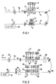
- Fig. 1 illustrates schematically a printing system according to one embodiment suitable for the process of the present invention. Details of Fig. 1 will be described shortly in the section of detailed description of embodiments.
- Fig. 2 illustrates schematically a printing system according to another embodiment suitable for the process of the present invention. Details of Fig. 2 will be described shortly in the section of detailed description of embodiments.
- the paper curl reduction process according to the invention may be achieved by applying a clear aqueous liquid on the non-imaging side of a substrate with the aqueous ink or inks being applied on the opposite side of the paper.
- the clear aqueous liquid and the aqueous ink or inks may be applied with or without heat. It is believed that the stress release caused by printing the clear aqueous liquid on one side of a substrate (e.g., paper) is balanced by applying the aqueous ink or inks on the other side of the substrate, thus reducing long-term paper curl (cool curl).
- the application of the clear aqueous liquid does not contribute to or affect the color of the non-imaging side (the side receiving the clear aqueous liquid) of the substrate and does not affect the appearance of the imaging side (the side receiving the aqueous ink or inks) of the substrate.
- This paper curl reduction process is useful for producing ink jet images on a single side (the side received the aqueous ink or inks) of a paper substrate.
- the aforementioned paper curl reduction process may also be repeated again to provide visible images on both sides of a substrate in a two sided (duplex) ink jet printing process.
- the imaged paper substrate from the single sided paper curl reduction printing process of this invention is subjected to a second aqueous ink(s) printing process on the nonimaging side (the side which did not previously receive the aqueous inks or inks).
- application of the clear aqueous liquid is optional and does not affect the previously formed images.
- a process for the reduction of curl in two sided (or duplex) ink jet printing comprises:
- the clear aqueous liquid of this invention can be applied to the substrate by utilizing an imaging device such as a continuous ink jet device, a thermal ink jet printhead, a piezoelectric device, an acoustic ink jet device, and other similar jet ink devices. Additionally, other means of providing water or moisture to the side of the paper may be employed such as a wet roll or brush, a steaming device, a spraying device, or the like. Preferably, a thermal ink printhead is utilized for this purpose.
- the printing pattern of the clear aqueous liquid on the non-imaging side of the substrate may be the same as or similar to the patterns or images that are printed by the aqueous ink or inks on the opposite side of the substrate.
- the printed pattern on the imaging side of the substrate is identical to the pattern of the clear aqueous liquid applied to the non-imaging side of the substrate.
- the print pattern of the clear aqueous liquid may be the same or different from that of the aqueous ink or inks. In this embodiment, the difference in stress between the two sides of the substrate is greatly minimized. This is especially important for printing a solid area image or when using applications of multiple inks on the substrate.
- the amount of clear aqueous liquid applied to the non-imaging side of the substrate may be adjusted depending on the need to reduce paper curl. For example, partial toning patterns including half tone, third tone, quarter tone, random pixels, etc. , or complete solid area coverage of the clear aqueous liquid may be employed.
- the application of the clear aqueous fluid to the non-imaging side of the substrate may be conducted at any stage of the ink printing process.
- the clear aqueous fluid may be applied either before, during, or after the printing of the ink or inks on the imaging side of the substrate.
- the clear aqueous liquid is applied to the non-imaging side of the substrate after the desired color or black image is created on the imaging side of the paper. This minimizes the need for any unnecessary equipment and paper handling operations.
- the clear aqueous fluid may be applied using single pass and/or checkerboarding techniques.
- the technique utilized for application of the ink on the imaging side of the substrate may be the same or different from the application technique utilized for the clear aqueous fluid on the non-imaging side of the substrate.
- a checkerboarding technique combined with a heat and delay technique is employed.
- Heat can be applied to the substrate either before, during or after application of the clear aqueous liquid on the substrate. Moreover, heat may be applied to the substrate at any time before, during or after the printing or application of the aqueous ink and the aqueous liquid.
- the heat may be applied using any suitable heating means including a heated belt, a heated platen, a heated roll, a lamp, a radiant heater, a microwave heater, etc. either with or without the assistance of vacuum and/or hot circulated air.
- the heating for drying the ink on the image side of the substrate is accomplished by the same mechanism utilized to dry the clear aqueous liquid on the non-imaging side of the substrate. Visible images on a single side of the substrate can be obtained with reduced curl.
- aqueous ink or inks employed in the two sided (duplex) ink jet printing of this invention are preferred to have the same or similar compositions for printing both sides of the substrate. Paper curl reduction may be achieved by the duplex ink jet printing (visible images on both sides of the substrate) either with or without the application of the clear aqueous liquid.
- the clear aqueous liquid may be applied selectively to any selected side of the substrate to achieve balanced paper stress and curl reduction.
- the clear aqueous liquid may be applied in certain selected areas on one side of the substrate, especially just opposite to a color or black solid area as long as the clear aqueous liquid does not cause distortion of the visible images.
- Applying partial tone or solid area of the clear aqueous liquid on the paper may be employed if desired.
- the clear aqueous liquid may be applied next to or over previously applied ink images provided the clear aqueous liquid does not affect or distort the desired ink images.
- Certain clear aqueous liquids are preferred for practicing the present invention in conjunction with aqueous ink jet inks.
- they are of low cost; they are compatible with many known humectants and ink jet ink ingredients; they may have high boiling points and low vapor pressures; they are suitable for imaging processes employing heat and delay techniques without generating a high concentration of vapor or odor; they are relatively non-toxic: they also do not easily plug or clog ink jet nozzles;they are inhibitive to bacteria growth; and they are easier to formulate than the aqueous ink or inks because lack of a solid colorant.
- the clear liquid of this invention may, for example, comprise water, solvent, optional humectant, surfactant, dispersing agent, bubble nucleation agent, pH buffering agent, anti-curl or anti-cockle agent, penetrant, biocide, chelating agent, anti-oxidation agent, water soluble polymer, and other desired chemicals.
- humectants include ethyleneglycol, diethylenenglycol, triethyleneglycol, tetraethyleneglycol, propyleneglycol, dipropyleneglycol, tripropyleneglycol, tetrapropyleneglycol, dimethylsulfoxide, sulfolane, betaine, urea, glycerine, glycerine propoxylates, glycerine ethoxylates, glycerine mixed ethoxylates and propoxylates, trimethylopropane ethoxylates, trimethylopropane propoxylates, trimethylopropane mixed ethoxylates and propoxylates, pentanediols including 1,5-pentanediol, hexanediols including 1,6-hexanediol, trimethylolpropane, hexanetriols including 1,2,6-hexanetriol, polyethyleneglyleneg
- the surface tension of the liquid can be controlled below 55 dyne/cm with the use of a surfactant or an organic solvent.
- the surfactant or dispersing agent can be an ionic (anionic, cationic, and amphoteric) or nonionic material.
- the clear aqueous liquid of this invention may have a composition similar to or the same as the aqueous ink(s) used for the imaging only without any colorant. It is preferred that the ink ingredients in the clear aqueous liquid does not contain any nonvolatile color material or contaminant.
- a simple composition of the clear aqueous liquid may comprise just water and a very small amount of surfactant.
- Aqueous ink or inks of this invention for single sided ink jet printing and two sided (duplex) ink jet printing can comprise water, colorants (dye(s) or pigment(s)), humectants, ink penetrants, bubble nucleation aids, anticurl agents, biocides, pH buffering agents, soluble polymers, antioxidants, anticlogging agents, antikogation agents, anticockle materials, surfactants, and dispersing agents.
- Ink jet inks selected for single sided and duplex printing are preferred to have all the desired attributes for high image quality, including excellent optical density and color gamut, adequate latency, and both short-term and long-term jetting performance.
- ink jet printing of the aqueous ink or inks may be carried out on the side of paper that previously did not receive the aqueous ink or inks. This is because the treatment of clear aqueous liquid of this invention does not produce visible images on the paper, thus, allowing any desired visible images to be printed again on the same side of the paper. This process produces visible ink jet images on both sides of a paper, which is one of the effective methods for duplex printing with low curl.
- the paper having an aqueous ink jet image can also be printed quickly on the nonimaged side with selected ink jet aqueous ink or inks comprising at least a dye or a pigment to give visible images on both sides of the paper with low curl.
- the duplex printing may also be carried out quickly in a sequential manner before any significant paper curl sets in, which would hinder subsequent duplex ink jet printing. Ink jet printing on both sides of a paper substrate minimizes the differential stress between the top and bottom surfaces and provides reduced curl.
- the same or different aqueous ink jet inks can be used in duplex ink jet printing.
- the aqueous ink jet inks used in the duplex printing may be selected from dye or pigmented based inks.
- the use of the clear aqueous liquid may not be necessary and it is optional depending upon the circumstances and requirements.
- the process for producing images on two side of a substrate with low curl can be a batch or a continuous printing process.
- the substrate employed can be any cut sheet or continuous web substrate compatible with aqueous-based inks, including plain paper, bond papers, commercial papers, coated papers, and ink jet transparency materials suitable for aqueous inks or ink jet printing processes.
- any suitable ink jet printing apparatus may be employed for the anti-curl printing process (process for the reduction of curl) of the present invention.
- Such an apparatus should be equipped with not only a printhead, software, computer, necessary hardware and electrical connections in an ink jet printer for printing ink, but also must include an applicator for possible applying to a substrate the clear aqueous liquid of the present invention.
- the ink jet printing device including printheads, printing assembly comprising several printheads (e.g., for printing black, cyan, magenta, yellow colorants) and full -width array printheads
- printing assembly comprising several printheads (e.g., for printing black, cyan, magenta, yellow colorants) and full -width array printheads
- printheads e.g., for printing black, cyan, magenta, yellow colorants
- full -width array printheads should be capable of applying the aqueous ink or inks to one or both sides of the substrate as well as capable of applying the clear aqueous liquid of the present invention to one or both sides of the substrate.
- Figs. 1 and 2 exemplify the basic elements of ink jet printing systems for single side and two sides (duplex) printing respectively according to the present invention.
- Fig. 1 represents an example of a thermal ink jet printing system of the present invention in which ink is printed on one side of a substrate 5 and the clear liquid of the present invention is applied on the other side of the substrate 6.
- the sheet Ss (substrate for single side ink jet printing) is caused to move in a printing process direction P by using different substrate advancing devices including a belt, rollers, guiding wheels, a rotating drum, a reciprocating platen etc
- rollers 4 or paper advancing devices with arrows indicating rotating direction
- other means may be used such as a belt, guiding wheels, a rotating drum or a reciprocating platen.
- the substrate Ss may be discontinuous.
- it can be cut with an optional cutter 9 to give a desired substrate length for the delivery of an imaging substrate to a single side printing output tray (SSPOT) 10.
- a printhead assembly 12 comprising black (K), cyan (C), magenta (M), and yellow (Y) printheads and their corresponding ink cartridges is located at one point along the process direction of the sheet Ss .
- the printhead assembly may be fed with an optional ink supply system 11, which comprises black, cyan, magenta, and yellow ink reservoirs with separate lines connecting them to their corresponding printheads (black, cyan, magenta, and yellow printheads).
- printheads may be utilized including one or more of desired ink jet printheads selected from continuous ink jet, piezoelectric, thermal ink jet, and acoustic ink jet printheads, as well as full-width array ink jet printheads (e.g., full-width thermal ink jet printheads).
- desired ink jet printheads selected from continuous ink jet, piezoelectric, thermal ink jet, and acoustic ink jet printheads
- full-width array ink jet printheads e.g., full-width thermal ink jet printheads
- multiple printheads may be utilized that would be capable of applying various color inks of one's choice.
- the printhead printing sequences for the application of color inks can be flexible (e.g., Y, C, M, K; Y, M, C, K ; K, M, C, Y; K, C, M, Y; etc.) and is not limited only to K, C, M, Y configuration as shown in Fig. 1.
- Single-pass as well as multiple-pass (e.g., moving the printheads across the substrate several times to complete the images) or checkerboarding ink jet printing processes may be utilized to create color and/or black images on the substrate.
- the ink jet printing can be carried out optionally either with or without heat which is provided by heating means 2 and 3 such as radiant heaters are shown in Fig. 1 for drying inks.
- Another printhead 14 is located downstream of the process direction for printing a clear aqueous liquid onto substrate side 6 which is opposite to imaging side 5 (comprising visible image) of substrate Ss . Even though the printhead 14 is illustrated as being located downstream from the ink jet printhead assembly 12, the printhead 14 may be located before or after the printhead assembly 12. If desired, the locations of 12 (visible ink printhead assembly) and 11 (visible ink reservoirs with connecting lines) can be transposed with 14 (clear aqueous liquid printhead,CALP) and 13 (cartridge or reservoir and connecting line for the clear aqueous liquid, CAL ). The clear aqueous liquid of the present invention is fed to the printhead 14 via supply 13.
- the printhead type may be identical to or different from that of the printhead assembly 12 (e.g., piezoelectric ink jet, thermal ink jet, acoustic ink jet, continuous ink jet, etc.) and may include any of the above-mentioned printheads.
- Other means of providing the clear aqueous liquid to the substrate Ss include a wet-rolling device, a steaming device, a spraying device, and the like.
- ink drying means 2 and 3 there is also disposed along the path of the sheet Ss ink drying means 2 and 3 as well as an optional substrate preheating device 1 including heated rollers or drums, heated belts, heated elements, lamp, a radiant heater, etc.
- the ink drying means 2 and 3 may be provided by applying heat to the substrate Ss using any known heating means including a heating belt, platen, or roll; a lamp; a radiant heater; a microwave heater; and the like, either with or without the assistance of vacuum and/or hot circulated air. Heat may be provided to the substrate before, during or after application of ink and/or the clear aqueous liquid.
- radiant heaters of the ink drying means 2 and 3 are placed below the substrate Ss and printheads 12 and 14 for providing heat to the substrate before, during, and after printing.
- Preheating device 1 and ink drying means 12 and 14 can be at any location in the ink jet printing process.
- Printhead 14 which applies the clear aqueous liquid, may be located on the same side or different side of the substrate as printhead assembly 12 and may be located before or after printhead assembly 12.
- the substrate Ss after application of inks from printhead assembly 12 or after application of the clear aqueous liquid from printhead 14, may be transposed for application of clear aqueous liquid or inks to the opposite side of the substrate Ss .
- Fig. 2 illustrates an alternative embodiment of the ink jet printing apparatus (device) according to the present invention.
- the substrate is moving in a process printing direction PD.
- ink may be applied to both sides of the substrate Sd (substrate for duplex ink jet printing).
- Ink jet printhead assemblies 22 and 29, which include any of the printheads mentioned herein and previously (e.g., can be similar or the same as printhead assembly 12 in Fig 1), apply aqueous inks via ink supplies 21 and 28 (can be in the form of ink reservoirs or cartridges ) of the same or different types of ink (e.g., black(K), cyan(C), magenta(M), and yellow(Y) with the same or different compositions) to the substrate Sd .
- Multiple printheads may be utilized for the application of various colors.
- Printheads 24 and 27 are fed with clear aqueous liquid(s) from supplies 23 and 26 (CAL) and may have the same or different clear aqueous liquid composition).
- the clear aqueous liquid supplied in one printhead may be the same as or different from the clear liquid supplied in the other (e.g., different humectants, different viscosities, different surface tensions, or containing different additives).
- the clear aqueous liquid may be applied to the substrate Sd by other means as mentioned herein or previously. Heat may be applied to the substrate Sd at any location, including before, during and after application of ink and/or clear aqueous liquid.
- Substrate advancing device 35 including rotating rollers, rotating wheels, transporting device for belt or platen, and guiding gears may be used.
- the location of the printheads for applying the aqueous inks and the clear aqueous liquids may be flexible with one being next to or on the same side as the other.
- the printhead arrangement and printing sequences for the application of color inks can be flexible (e.g., Y, C, M, K; Y, M, C, K; K, M, C, Y; K, C, M, Y; etc.) and is not limited to K, C, M, Y as shown in Fig. 2.
- the use of printheads 24 and 27(CALP) with their corresponding clear aqueous liquids (CAL) in duplex printing can be optional and selective in printing patterns as long as the objectives of reduction of paper curl is achieved for this invention.
- the application of the clear aqueous liquid may not be needed since printing on both sides of a substrate (Sd ) with the same or similar aqueous inks can counterbalance the stress release due to the application of the aqueous inks.
- duplex ink jet printing can be achieved with visible images on two side of the substrate (paper) without using the clear aqueous liquids.
- the application of clear aqueous liquids can be carried out for curl reduction without distorting the desired visible images. Desired printing patterns (partial tone or full tone, or random pixels, etc.) for the clear aqueous liquids to reduce curl can be predetermined and selectively executed by software and computer without interferring with printing of the visible images.
- the substrate Sd may be utilized in a printing system according to Fig. 2 or in a printing system according to Fig. 1 in which the substrate Ss ( Ss in Fig. 1) is fed past the printheads 12 and 14 two or more times (the first time printing visible images on the top side of the substrate and second time printing visible images on the bottom side of the substrate before collecting the final substrate with images on both sides in the output tray).
- all of the printhead assemblies 22 and 29 and printheads 24 and 27, in Fig. 2 may be independently selected to be located either on one side or the opposite side of the substrate Sd with the substrate being transposed between application of ink and/or clear aqueous liquid from printhead assembly 22 and printhead 24 as well as printhead assembly 29 and printhead 27 for application of ink and/or clear aqueous liquid to the desired side of the substrate Sd .
- printhead assembly (comprising K, C, M, Y printheads ) 22 may be located on one side of the substrate for printing inks and the printhead assembly (comprising K, C, M, Y printheads) 29 can be located on the opposite side of the substrate.
- Fig. 2 the substrate Sd is shown in a horizontal position and the printhead assemblies 22 and 29 and printheads 24 and 27 deliver inks and the clear aqueous liquids downward onto the substrate.
- the substrate that receives the inks to give visible images can be arranged in any desired position ( e.g. vertical or inclined, or horizontal position) and it is not only restricted to a horizontal position.
- the substrate is not in a horizontal position for receiving the inks and the clear aqueous liquids as in the case of another embodiment (not shown in Fig 2), proper arrangement should be made so that printhead assembly 22 and printhead 24 for inks and the clear aqueous liquid will print on one side of the substrate while the printhead assembly 29 and printhead 27 for the aqueous inks and the clear aqueous liquid may print on the opposite side of the substrate.
- a substrate (paper) cutter 36 can be optionally installed to cut the substrate to any desired length when a continuous web substrate is used.
- the substrate output tray (Duplex Output Tray, DOT) 37 is employed to receive the final product of printed substrates with images on both sides with reduced curl. If desired, the final product of print substrates can be stapled (not shown in Fig. 2) before its delivery to the output tray 37.
- anti-curl agents may be used, if necessay, in the aqueous ink or inks and the clear aqueous liquid of the present invention and include different molecular weights of derivatives of glycerine (glycerol) propoxylates, glycerine (glycerol) ethoxylates, glycerine (glycerol) mixed ethoxylates and propoxylates, trimethylopropane propoxylates, trimethylopropane ethoxylates, trimethylopropane mixed ethoxylates and propoxylates, and other known anti-curl agents.
- the anti-curl agents are generally present in an amount of from about 0 to about 30% by weight of the ink, preferably from about 0.5 to about 20% by weight, and more preferably from about 1.0 to about 15% by weight.
- the liquid vehicle of the aqueous inks and clear aqueous liquids employed for the process of the present invention may consist of water, or it may comprise a mixture of water and miscible or soluble organic components (humectants or solvents), such as glycol derivatives including ethylene glycols, propylene glycols, diethylene glycols, triethyleneglycol, dipropylene glycols, tripropyleneglycol, polyethylene glycols, polypropylene glycols; diols including petanediols (e.g.
- hexanediols e.g., 1,6-hexanediol, etc.
- triols including trihydroxyhexane(1,2,6-trihydroxyhexane), glycerine (glycerol), trimethylolpropane and their condensation products of ethyleneoxide and alkylethyleneoxides (e.g., glycerine (glycerol) propoxylate, glycerine (glycerol) ethoxylate, glycerine (glycerol) mixed ethoxylates and propoxylates, trimethylopropane propoxylate trimethylopropane ethoxylate trimethylopropane mixed ethoxylates and propoxylates; amides including N-alkylpyrrolidinones (N-methylpyrrolidinone, N-cyclohexylpyrrolidinone, etc.); urea; ethers including glycol, etc.; glycerine (gly
- the water to organic ratio may be in any effective range, and typically is from about 100:0 to about 30:60, preferably from about 98:2 to about 40:60, and more preferably from about 97:3 to about 50:50, although the ratio can be outside these ranges.
- the non-water component of the liquid vehicle generally serves as a humectant or solvent, which has a boiling point higher than that of water (100° C.).
- the liquid vehicle is generally present in an amount of from about 50 to about 100.0 percent by weight, preferably from about 60 to about 98.0 percent by weight, and more preferably from about 70 to about 95.0 percent by weight, although the amount can be outside these ranges.
- aqueous inks Various materials, humectants or mixtures thereof can be selected for the aqueous inks and the clear aqueous liquids of the present invention providing the objectives thereof are achievable.
- Important characteristics relating to the selection of an appropriate material or solvent include good compatibility with water; desirable vapor pressures; low toxicity properties; desirable intrinsic viscosities, for example, less than about 7 centipoises; surface tension values exceeding, for example, greater than 25 dynes/centimeter; and further, those materials in water will enable the substantially complete dissolution of the dye components (for inks only).
- organic materials selected for the ink compositions and the clear aqueous liquids of the present invention include tetramethylene sulfone, available as Sulfolane ®; 1,1,3,3-tetramethyl urea; 3-methyl sulfolane; 1,3-dimethyl-2-imidazolidone; and the like.
- Preferred materials, since they possess many desirable properties inclusive of substantially low toxicity characteristics, are sulfone derivatives such as sulfolane.
- Other materials may be selected providing the objects of the present invention are achievable including, for example foramides, and the like.
- the amount of the solvent may range from 0 to about 50 percent by weight, preferably from about 0.5 to 30 percent by weight, and more preferably from about 1.0 to 20 percent by weight.
- Preferred co-solvents or humectants are diols such as ethyleneglycol, propyleneglycol, polyethyleneglycol, polypropyleneglycol, etc. or triols such as glycerine (glycerol), trimethylolpropane (TMP), and their condensation products with ethyleneoxide and alkyleneoxides (e.g., propyleneoxide, butyleneoxide, etc.), sulfolane, and other previously mentioned humectants.
- diols such as ethyleneglycol, propyleneglycol, polyethyleneglycol, polypropyleneglycol, etc. or triols such as glycerine (glycerol), trimethylolpropane (TMP), and their condensation products with ethyleneoxide and alkyleneoxides (e.g., propyleneoxide, butyleneoxide, etc.), sulfolane, and other previously mentioned humectants.
- the colorant for the aqueous inks employed for the process of the present invention can be a dye.
- the dye is present in any effective amount, typically from about 0.1 to about 20 percent by weight, preferably for about 0.5 to about 10 percent by weight, and more preferably from about 1.0 to about 7.0 percent by weight.
- the colorant for the aqueous ink compositions of the present invention can be a pigment, or a mixture of one or more dyes and/or one or more pigments.
- the pigment can be black, cyan, magenta, yellow, red, blue, green, brown, mixtures thereof, and the like.
- suitable black pigments include various carbon blacks such as channel black, furnace black, lamp black, and the like.
- Colored pigments include red, green, blue, brown, magenta, cyan, and yellow particles, as well as mixtures thereof.
- Preferred pigments of this invention are nontoxic and AMES test negative materials (carbon blacks and color pigments) which include nonmutagenic and noncarcinogenic pigments for safety reasons.
- carbon blacks and color pigments which include nonmutagenic and noncarcinogenic pigments for safety reasons.
- pigment dispersions prepared by the process set forth herein may be employed in the ink compositions for ink jet printing.
- Such dispersions for the preparation of pigment inks are provided by mixing pigments with at least a dispersant or a dispersing agent selected from anionic, cationic, nonionic dispersants, and compatible mixtures thereof (e.g. mixtures of anionic and nonionic dispersants, mixtures of cationic and nonionic dispersants), water as well as other optional chemical additives.
- the pigment particle size in the aqueous inks or dispersions is as small as possible to enable a stable colloidal suspension of the particles in the liquid vehicle with good color strength and to prevent clogging of the ink jet channels or nozzle openings when the ink is used in a thermal ink jet printer.
- Average particle sizes are generally from about 0.001 to about 5 micrometers, preferably from about 0.01 to about 3 micrometers, and more preferably from about 0.01 to about 1.2 micrometers, although the particle size can be outside these ranges.
- a more preferred pigment particle size in the inks of this invention includes particles having at least 50% of the particles being below 0.3 micrometer with no particles being greater than 3.0 micrometers (measured on a Hodaka CAPA 700 Particle Size Analyzer). More preferably, the pigment particle size of the ink includes particles having at least 70% of the particles being below 0.3 micrometer with no particles being greater than 1.0-1.2 micrometer.
- the pigments may be sonified, centrifuged and filtered to provide the desired particle size.
- the pigment is present in the ink composition in any effective amount, generally from about 1 to about 20 percent by weight, preferably from about 2 to about 10 percent by weight, and more preferably from about 4 to about 8 percent by weight.
- the pigment in the aqueous inks is dispersed in water with one or more dispersants.
- the dispersants can be anionic, cationic, and nonionic types especially those ionic dispersants which have both ionic (capable of ionization in water) and hydrophobic (affinity for pigments) moieties.
- the remainder of the dispersion may comprise nonactive ingredients such as water, solvent or humectant and chemical additives.
- the average molecular weight of the dispersant is generally less than 20,000, preferably less than 13,000, and more preferably less than 10,000.
- the pigment dispersion should contain enough dispersant to stabilize the pigment particles in water and ink, but not so much as to adversely affect properties of the dispersion such as viscosity, stability, and optical density.
- Pigment dispersions for aqueous pigment inks may be prepared by mixing at least one dispersant (e.g., a product of formaldehyde and sodium naphthalene sulfonate or a product of an aldehyde and a derivative of naphthalene sulfonic acid salt, etc. ), pigment, and water in a mixer such as an attritor, sandmill, homogenizer, fluidizer including a microfluidizer, high speed mixer, and the like, with or without an optional grinding medium, such as stainless steel balls, ceramic chips, and the like.
- a mixer such as an attritor, sandmill, homogenizer, fluidizer including a microfluidizer, high speed mixer, and the like
- an optional grinding medium such as stainless steel balls, ceramic chips, and the like.
- surfactants or wetting agents can be added to the ink. These additives may be of the cationic, anionic, or nonionic types. These surfactants and wetting agents are present in pigment inks or dispersions in effective amounts, generally from 0 to about 15 percent by weight, preferably from about 0.01 to about 10 percent by weight, and more preferably from about 0.02 to about 8 percent by weight.
- Polymeric chemical additives can also be added to the inks and the clear aqueous liquids employed in the process of the present invention to enhance the viscosity of the ink and the clear aqueous liquids, including water soluble polymers.
- Polymeric additives may be present in the ink or the clear aqueous liquids of the present invention in amounts of from 0 to about 10 percent by weight, preferably from about 0.001 to about 8 percent by weight, and more preferably from about 0.01 to about 5 percent by weight.
- additives to the inks and the clear aqueous liquids employed in the process of the present invention include biocides to inhibit bacteria growth; penetration control additives ( or penetrants) present in an amount of from about 0.01 to about 20 percent by weight, more preferably from about 0.01 to about 15 percent by weight; pH controlling agents present in an amount of from 0 to about 10 percent by weight, preferably from about 0.001 to about 5 percent by weight, and more preferably from about 0.01 to about 4 percent by weight.
- Other optional ingredients in the inks or the clear aqueous liquids include chelating agents. The concentration of the ingredients can be varied from about 0 to about 10 percent, preferably from about 0.1 to about 8 percent, and more preferably from about 0.1 to about 5 percent by weight in the ink.
- Suitable ink or clear aqueous liquid additives include those disclosed in U.S. Patent No. 5,223,026 and U.S. Patent No. 5,207,825.
- the aqueous inks and the clear aqueous liquids of the present invention may contain an ionic compound other than dye at least partially ionizable in the liquid vehicle for desired coupling with microwave for drying.
- the ionic compound is selected so that a relatively small amount is in the ink to obtain the desired conductivity.
- the ionic compound exhibit a high degree of dissociation in the aqueous liquid vehicle of the ink and the clear aqueous liquids, since a higher degree of dissociation results in more free ions present in the liquid and thus results in higher conductivity for a given molar amount of the ionic compound.
- preferred ionic compounds exhibit a degree of dissociation of about 100 percent, although ionic compounds exhibiting lower degrees of dissociation can also be used.
- ionic compounds that enable higher ink conductivity per weight unit of ionic compound present in the ink and the clear aqueous liquids are preferred in conjunction with the use of microwave heaters for drying the inks and the clear aqueous liquids.
- compounds containing low molecular weight cations and anions generally result in higher conductivity per weight unit of compound present in the ink and the clear aqueous liquids than do ionic compounds containing high molecular weight cations and anions.
- an ink or a clear aqueous liquid containing 1 percent by weight of lithium chloride exhibits higher conductivity than an ink containing 1 percent by weight of potassium iodide, since the ink containing lithium chloride contains more free ions per unit of weight than the ink containing potassium iodide.
- Ionic compounds wherein only a small amount is required in the ink or the clear aqueous liquid to achieve the desired conductivity are particularly preferred when the other ink components or characteristics, such as the dye or the pigment colloidal dispersion stability, can be adversely affected by the presence of large amounts of ions.
- the optional use of the ionic compound preferably is selected to optimize solubility of the other ingredients.
- the amount of the ionic compound other than dye present in the aqueous ink or the clear aqueous liquid for microwave drying can vary.
- the ink contains from about 0 to about 20 percent by weight of the ionic compound other than dye; for inorganic and organic salts, preferably the ink contains from about 0.01 to about 10 percent, and more preferably from about 0.1 to about 5 percent by weight of the ionic compound, although the amounts can be outside of these ranges provided that the conductivity objectives for drying of the present invention are achieved.
- the amount of the ionic compound present generally will also depend on the size and valency of the ions in the compound, the desired printing process speed, the desired ink conductivity, the size of the image with respect to dimensions and ink deposition density (milligrams per square centimeter) on paper, the power level of the microwave drying apparatus, and the like.
- Aqueous ink compositions according to the present invention may be provided by mixing aforementioned pigment dispersions with the previously mentioned solvents, humectants, and other ink additives (or ingredients).
- the mixing can be done by various methods including homogenizing, sonification, microfluidization, mechanical mixing, magnetic stirring, high speed jetting, and the like.
- the sonification or homogenizing process is preferred since such process provides a homogeneous dispersion of pigment particles by evenly distributing the dispersant throughout the pigment ink.
- Microfluidization can also be used for large scale production of the pigment dispersion and inks.
- pigment inks suitable for the present invention can be prepared by any process suitable for preparing aqueous-based inks.
- the ink ingredients can be mixed in the desired amounts and stirred until a uniform ink composition results (typically about 30 minutes, although the mixing/stirring time can be either greater or less than this period). While not required, the ink ingredients can be heated during mixing if desired. Subsequent to mixing and stirring as well as centrifugation, the ink composition generally is filtered to remove any solid or particulate matter greater than 3.0 microns. Any other suitable processes for preparing the inks may also be employed.
- the surface tension of the aqueous inks and the clear aqueous liquids are greater than 0.025N/m (25 dynes/cm).
- the viscosity of the ink or the clear aqueous liquids is usually less than 0.02 Pas (20.0 cps).
- the aqueous inks or the clear aqueous liquids of the present invention possess excellent latency.
- the inks possess a latency of at least 10 seconds, more preferably on the order of 20 seconds to greater than 1000 seconds, with a minimum latency of at least 20 seconds being preferred when a 600 spi printhead is employed.
- the aqueous ink and the clear liquid are applied to a suitable substrate in an image-wise fashion.
- Application of the ink to the substrate can be conducted by any suitable printing process compatible with aqueous-based inks, such as pen plotters, continuous stream ink jet printing, drop-on-demand ink jet printing (including piezoelectric, acoustic and thermal ink jet printing processes), or the like.
- Single pass as well as multiple pass or checkerboarding ink jet printing processes may be used to create color and/or black images on the substrate. Checkerboarding in combination with heat and delay techniques are preferred.
- the heat can be provided to the substrate by any known heating means including a heated belt, platen, roll, lamp, radiant heater, microwave heater, laser diodes, and the like, either with or without the assistance of vacuum and/or hot circulated air.
- microwave heaters are utilized when employing the ionic ink additive.
- Suitable ink jet printers employing microwave dryers include those disclosed in U.S. Patent No. 5,220,346 to Carreira et al., the subject matter of which is totally incorporated herein by reference.
- the ink jet printing processes and the compositions of the aqueous inks and the clear aqueous liquids of this invention can have a broad scope and a wide variations.
- the following examples are provided only for illustrative purposes.
- Other variations of the ink jet printing process and the compositions of the aqueous inks and the clear aqueous liquids for curl reduction can also be employed by those skilled in the art and are also included within the spirit and the scope of this invention.
- a Hewlett Packer HP-1200C color thermal ink jet ink jet printer is employed.
- a substrate is heated (using radiant heaters) during printing either with or without checkerboarding.
- Printing modes such as a) Paper-fast mode (single pass without checkerboarding, PF), b) High Quality mode (checkerboarding and heat in HQ mode) and c). Normal mode (checkerboarding and heat, N mode) are employed to print a large solid area (20.4x25.8cm) on a 21.6x27.9cm paper with four surrounding white boarders.
- Hewlett Packer HP-1200C black and color inks carbon black ink, cyan, magenta, and yellow dye inks
- CH 3 color set aqueous inks cyan, magenta, and yellow dye inks
- new inks and a clear aqueous liquid
- Various plain papers with different sizing, paper weight, and fabrication process Alkaline or Acidic process are used. After the application of water, the papers with or without ink jet image are allowed to dry at least overnight before measuring the curl properties.
- Paper curl data are obtained in terms of curl radius, average paper heights for four corners of a paper, and average paper height near the centers of the long side of a paper (centers of 27.9cm sides).
- the curve radius is obtained by a free hanging method.
- a paper clip is attached to the center of a paper (short side, 21.6cm side) being measured and allowed the paper to freely suspend in the air.
- the curvature of the paper curl is determined by matching the paper curling shape near the edge with a template which had curves of known radius of curvature. A large number of curl radius indicates less paper curl.
- Average paper corner height was determined by placing a paper imaged with an ink jet ink or a clear aqueous liquid on a flat surface and the sum of the heights for four corners are obtained and divided by four.
- a large number of average paper corner height represents a severe paper curl problem (all A cases in Tables II and III).
- a small number of the average paper height indicates low paper curl (desirable, all B cases in Tables II and III).
- average paper center height was also determined similarly except the center heights on the long sides (along 27.9cm side of a 21.6x27.9cm paper) of a paper are measured and averaged. A small number reflects low curl.
- Paper curl is formed by printing solid area on papers with either water or an ink comprising water.
- a clear aqueous liquid comprising water and a small amount (@0.01%) of surfactant (Igepal CO-630) is prepared.
- the clear aqueous liquid has a surface tension of 0.0335N/m (33.5 dyne/cm) at room temperature.
- the clear aqueous liquid is placed into a cleaned and empty HP-1200C cyan ink cartridge for the printing to demonstrate the effect of water on paper curl (Table I).
- HQ mode high quality mode
- the HQ mode employs heat and checkerboarding (partial tone printing) method during printing.
- CH 3 set of aqueous color inks (CH 3 cyan ink, CH 3 magenta ink, and CH 3 yellow ink) are prepared and used in paper curl studies. The compositions of these inks in weight percentage are shown below. 1).
- CH 3 cyan ink Project cyan dye (ICI 10% liquid dye concentrate, 35.0% solid), butylcarbitol (10.0%), N-cyclopyrrolidinone (2.0%), sulfolane (15.0%), polyethyleneoxide (0.07%), and water (balance). 2).
- CH 3 Magenta ink Mitubishi magenta dye (4.0%), butylcarbitol (10.0%), N-cyclopyrrolidinone (2.0%), sulfolane (15.0%), polyethyleneoxide (0.05%), and water (balance). 3).
- CH 3 yellow ink Project yellow 1G (4.0%), butylcarbitol (10.0%), N-cyclopyrrolidinone (2.0%), sulfolane (15.0%), polyethyleneoxide (0.03%), and water (balance). Printing solid area with these inks on one side of a paper causes the formation of paper curl which can be minimized by this invention.
- Hewlett Packard HP-1200C ink jet inks (Cyan, Magenta, Yellow, dye inks and carbon black pigment ink) are also employed in solid area printing to generate paper curl, which is significantly reduced by the process of this invention.
- aqueous inks and clear aqueous liquid are printed on different plain papers with a HP-1200C thermal ink jet printer and the printed samples are dried at least overnight under the laboratory conditions to allow the papers to reach equilibrium.
- the clear aqueous liquid of the present invention including water and a small amount (@0.01%) of surfactants (Igepal CO-630) is used in printing the back side of a paper which was previously imaged by a thermal ink jet method with an aqueous ink (e.g. HP-1200C ink jet ink) and showed curl upon aging.
- aqueous ink e.g. HP-1200C ink jet ink
- Tables II and III The results of curl reduction for the back side printing of the papers containing ink jet images (front side) using a clear aqueous liquid are shown in Tables II and III. In all A cases (e.g. 1A, 2A, 3A,... etc.) the paper curl was generated by printing an ink jet ink on one side of paper only followed by air drying under ambient conditions.
- Xerox 4200 GP Pensacolola Scroll (TI) 0.11 Not Measurable Not Measurable CH 3 Red / None HQ 7B.
- Solid area printing on a plain paper with an ink jet ink causes undesired paper curl upon aging.
- an aqueous ink jet ink e.g. CH 3 Magenta ink, CH Cyan ink, HP-1200C inks, etc.
- aqueous ink jet ink e.g. CH 3 Magenta ink, CH Cyan ink, HP-1200C inks, etc.
- the reduction of paper curl is possibly due to the decrease of the differential stress between the top and bottom surfaces of a paper caused by water in the aqueous inks.
- This Example shows in many cases ( cases 1, 4, and 5) that the curl reduction is achieved by printing the back side of an imaged paper with an aqueous ink jet ink (either the same (case 2) or different ink (all other cases) from the first printing ink) comprising water.
- the color ink composition and mode of printing can be either the same or different between the first printing ink and the second printing ink.
- Back side printing of an imaged paper (DUPLEX printing) can be carried out in any desired pattern including partial tone (1/4 tone, 1/2 tone, text, graphic, etc.) and full tone ( solid area) as long as the reduction of paper curl of this invention is achieved.
- back printing with full tone (solid area printing) image is employed to simulate a severe case for demonstration purposes.
- the clear aqueous liquid of the present invention is not used in this demonstration.
- the results are shown in Table IV
- Ink known to cause paper curl in single side printing (symbol *) does not give bad paper curl in the two sided ink jet printing (Duplex ink jet printing).
- Duplex ink jet printing has been shown to be desirable not only for saving paper consumption but also reduces paper curl as demonstrated in this Example.
Abstract
Description
- This invention relates to anti-curl printing methods for ink jet printers. The present invention also relates to printing process, apparatus, and materials for ink jet technologies that reduce curl in printed paper elements. In addition, it also relates to the production of ink jet images of aqueous inks on a single side or two sides of a substrate with reduced curl.
- Ink jet printing is a non-impact method that produces droplets of ink that are deposited on a substrate such as paper or transparent film in response to an electronic digital signal. Thermal or bubble jet drop-on-demand ink jet printers have found broad application as output for personal computers in the office and the home.
- Ink jet printing systems generally are of two types: continuous stream and drop-on-demand. In continuous stream ink jet systems, ink is emitted in a continuous stream under pressure through at least one orifice or nozzle. Multiple orifices or nozzles also may be used to increase imaging speed and throughput. The ink is ejected out of orifices and perturbed, causing it to break up into droplets at a fixed distance from the orifice. At the break-up point, the electrically charged ink droplets are passed through an applied electrode which is controlled and switched on and off in accordance with digital data signals. Charged ink droplets are passed through a controllable electric field, which adjusts the trajectory of each droplet in order to direct it to either a gutter for ink deletion and recirculation or a specific location on a recording medium to create images. The image creation is controlled by electronic signals.
- In drop-on-demand systems, a droplet is ejected from an orifice directly to a position on a recording medium by pressure created by, for example, a piezoelectric device, an acoustic device, or a thermal device controlled in accordance with digital data signals. An ink droplet is not generated and ejected through the nozzles of an imaging device unless it is needed to be placed on the recording medium.
- Since drop-on-demand systems require no ink recovery, charging, or deflection operations, the system is simpler than the continuous stream type. There are three types of drop-on-demand ink jet systems. One type of drop-on-demand system has an ink filled channel or passageway having a nozzle on one end and a regulated piezoelectric transducer near the other end to produce pressure pulses. The relatively large size of the transducer prevents close spacing of the nozzles necessary for high resolution printing, and physical limitations of the transducer result in low ink drop velocity. Low drop velocity may seriously diminish tolerances for drop velocity variation and directionality, thus impacting the system's ability to produce high quality copies, and also decreases printing speed. Drop-on-demand systems which use piezoelectric devices to eject the ink droplets also suffer the disadvantage of a low resolution. A second type of drop-on-demand ink jet device is known as acoustic ink printing which can be operated at high frequency and high resolution. The printing utilizes a focused acoustic beam formed with a spherical lens illuminated by a plane wave of sound created by a piezoelectric transducer. The focused acoustic beam reflected from a surface exerts a pressure on the surface of the liquid, resulting in ejection of small droplets of ink onto an imaging substrate. Aqueous inks can be used in this system.
- The third type of drop-on-demand system is known as thermal ink jet, or bubble jet, and produces high velocity droplets and allows very close spacing of nozzles. The major components of this type of drop-on-demand system are an ink filled channel having a nozzle on one end and a heat generating resistor near the nozzle. Printing signals representing digital information generate an electric current pulse in a resistive layer (resistor)within each ink passageway near the orifice or nozzle, causing the ink in the immediate vicinity of the resistor to be heated up periodically. Momentary heating of the ink leads to its evaporation almost instantaneously with the creation of a bubble. The ink at the orifice is forced out of the orifice as a propelled droplet at high speed as the bubble expands. When the hydrodynamic motion of the ink stops after discontinuous heating followed by cooling, the subsequent ink emitting process is ready to start all over again. With the introduction of a droplet ejection system based upon thermally generated bubbles, commonly referred to as the "bubble jet" system, the drop-on-demand ink jet printers provide simpler, lower cost devices than their continuous stream counterparts, and yet have substantially the same high speed printing capability.
- The operating sequence of the bubble jet system begins with a current pulse through the resistive layer in the ink filled channel, the resistive layer being in close proximity to the orifice or nozzle for that channel. Heat is transferred from the resistor to the ink. The ink becomes superheated far above its normal boiling point, and. for water based ink, finally reaches the critical temperature for bubble nucleation and formation of around 280°C and above. Once nucleated and expanded, the bubble or water vapor thermally isolates the ink from the heater and no further heat can be applied to the ink. This bubble expands rapidly due to pressure increase upon heating until all the heat stored in the ink in excess of the normal boiling point diffuses away or is used to convert liquid to vapor, which removes heat due to heat of vaporization. The expansion of the bubble forces a droplet of ink out of the nozzle located either directly above or on the side of a heater, and once the excess heat is removed with diminishing pressure, the bubble collapses on the resistor. At this point, the resistor is no longer being heated because the current pulse has been terminated and, concurrently with the bubble collapse, the droplet is propelled at a high speed in a direction towards a recording medium or substrate. Subsequently, the ink channel refills by capillary action and is ready for the next repeating thermal ink jet process. This entire bubble formation and collapse sequence occurs in about 30 microseconds. The heater can be reheated to eject ink out of the channel after 100 to 2,000 microseconds minimum dwell time and to enable the channel to be refilled with ink without causing any dynamic refilling problem. Thermal ink jet processes are well known and are described in, for example, U.S. Patent 4,601,777, U.S. Patent 4,251,824, U.S. Patent 4,410,899, U.S. Patent 4,412,224, U.S. Patent 4,463,359, U.S. Patent 4,532,530, U.S. Patent 5,281,261, U.S. Patent 5,139,574, U.S. Patent 5,145,518.
- Ink jet printing is a non-impact method that produces droplets of ink that are deposited on a substrate such as plain paper or coated paper or textile cloth or transparent film in response to an electronic digital signal. Thermal or bubble jet ink jet printers which are operated in a drop-on-demand mode have found broad applications in digital printers, plotters, and fax machines as output for personal computers and large computers in the office and the home.
- In a single-color ink jet printing apparatus, the printhead typically comprises a linear array of ejectors, and the printhead is moved relative to the surface of the print sheet (substrate or recording medium), either by moving the print sheet relative to a stationary printhead, or vice-versa, or both. In some types of apparatus, a relatively small printhead or an array of two or more printheads in a partial width printer moves across a print sheet (substrate) numerous times in swathes, much like a typewriter. Alternatively, a printhead, which consists of an array of ejectors and extends the full width of the print sheet, may pass ink down the print sheet (substrate) one line at a time before the print sheet is advanced to complete the production of full-page images in what is known as a "full-width array" (FWA) printer. When the printhead and the print sheet are moved relative to each other, image-wise digital data is used to selectively activate the thermal energy generators (resistors) in the printhead over time so that the desired image will be created on the print sheet.
- In the thermal ink jet printing water is usually a key component, which is responsible for the bubble formation and propelling the ink out of nozzles toward the imaging substrate (print sheet). The use of water in large concentrations, however, has also some disadvantages. Water has a fast evaporation rate relative to high boiling organic solvents (e.g. humectants, anti-curl agents, etc.). Ink ingredients such as water soluble or water compatible dyes, pigments, biocides, and other chemical additives may become destabilized due to the loss of water during idling time. As a result printheads may become plugged, which produce some jetting failure. Water also interacts with paper to cause two major distortions known as paper cockle and paper curl. Paper cockle is a distortion in which bumps, indentations and other irregularities are randomly produced on the printed paper, giving the paper a "wrinkled" appearance. Curl is a phenomena in which the edges or corners of the paper migrate towards (toward imaging side) or away from (away from the imaging side) the center of the paper. Curl is possibly caused by the printed aqueous ink on one side of the paper releasing stress on the surface of the paper which induces a differential paper stress or uneven stress between top and bottom surfaces for the paper after drying and aging. The direction of curl may be toward the printed (imaged) side of the paper, or it may be toward the non-printed (non-imaged) side. For the purpose of this invention, paper "curl" is defined as including both curling and cockling of the paper substrate.
- Curl may appear immediately after printing or may take a day or two to manifest. In its final state, the paper sheet in a severe case may take the form of a tube, a roll, or a scroll. Curled paper cannot be stacked sheet upon sheet, thereby causing much inconvenience to the user. Curled sheets are difficult to display or store and cannot be used in processes requiring near planarity, such as media feeding, tracking, and print alignment. Curl is most prevalent in solid area printing and is therefore a more acute problem in graphics than in text printing. For the same reason, it is also a concern in four color printing especially when it involves printing composite colors or where graphics are prominent. Curl is also a problem when a large quantity of ink is needed to achieve high optical density images.
- The severity of the paper curl may be affected by the property of the plain and coated paper substrates, the type of aqueous ink used in the printing, temperature of the substrate during printing, and the ink jet printing process. Papers that have a small built-in differential stress between the top and bottom surfaces in the paper manufacturing process may provide little curl after ink jet printing. On the other hand papers with a large built-in differential stress between the top and bottom surface will tend to exhibit significant paper curl after ink jet printing. The degree of differential stress that is built into the papers depends on the conditions of the paper manufacturing process. Papers that are thicker or heavier and have a stronger mechanical strength tend to give lower degree of paper curl as compared to those thinner papers with weaker mechanical strength. Once a paper used in the ink jet printing is selected then the fate of curl formation is somewhat fixed. Some papers will develop curl much easier than others. In an ordinary office environment, plain and coated papers are used in the ink jet printing. Depending on the paper supply situation in the office, a customer may not have a chance to select a proper paper with a smaller curl property for the ink jet printing. There is a need to have a process that reduces paper curl with minimum impact from the paper.
- Inks having a large amount of anticurl agent may reduce the curl. However, the use of the required amount of the anticurl agents in the inks may increase the viscosity of the ink and causes great difficulty in jetting the inks, especially after some idling in a printhead. This is especially true when water evaporates near the nozzles during idling time, resulting in a dramatic increase in ink viscosity and possible jetting failure. Water evaporation during idling time can also cause crystallization and precipitation of dyes or agglomeration of pigments. Most of the anticurl agents have high boiling point and high viscosity. Thus, the use of high viscosity anticurl agents in required large quantities may cause short ink latency and increase jetting difficulty. This is especially true when a high resolution ink jet printhead is used, which has a narrow nozzle opening (about 10 to 49 microns for a 400 and 600 spots per inch resolution printhead as compared to greater than 49 microns in a 300 spots per inch resolution printhead). Due to these aforementioned limitations there is a need to develop a process for the ink jet printing whereby ink jet printing of solid area images for graphic applications can be easily carried out to give reduced paper curl.
- In ink jet printing, it is desirable to reduce the consumption of paper for economic and environmental reasons. Duplex printing sometimes may be desired. However, if a paper has been printed with aqueous ink jet images having solid areas the paper may form curl or cockle, which prohibits smooth paper feeding in subsequent ink jet printing. Thus, printing duplex (on two sides of a paper) can be difficult if the imaged paper is not treated quickly after printing. Paper curl progressively becomes worse upon aging after printing. There is a need to provide a means for both single sided ink jet printing and two sided (duplex) ink jet printing to provide images on papers with reduced curl.
- Ink jet printing (checkboarding or single pass) may also affect paper curl in multiple color printing especially printing that involves a solid area image. There is also a need to provide a decurling process to reduce paper curl.
- Depending on the type of color images printed, paper curl caused by aqueous ink jet inks may vary. For example, printing blue, green and red images on a paper requires the use of several inks (e.g., 200% of normal ink coverage) which is significantly more than when printing single color cyan, magenta and yellow images (e.g. 100% of normal ink coverage). As a consequence, the printing of solid area images of blue, green and red (composite colors) create a greater paper curl problem than those of single color images (e.g., cyan, magenta and yellow). Increased curling also can be found when solid areas of images are printed in a single pass mode rather than multiple passes (e.g., checkerboarding) mode.
- In an effort to reduce cockle and curl in ink jet printers, efforts have been made to provide anti-curl and anti-cockling agents to reduce this problem. For example, U.S. Patent No. 5,356,464 to Hickman et al. describes anti-curl agents at a desired amount that may be utilized in ink jet inks. However, such anti-curl agents negatively affect the stability of inks by increasing the viscosity. Such inks decrease latency and increase clogging of ink jet printhead nozzles.
- U.S. Patent No. 5,207,824 to Moffatt et al. describes an ink jet ink comprising an anti-cockling agent for thermal ink jet printers. In some cases, the use of a required amount of anticockling agents in the inks to reduce curl tends to aggravate the nozzle pluggage and jetting failure. This is possibly due to their contribution of the viscosity increase of inks and incompatibility of ink ingredients with some dyes or pigments. The effective use of anticockling agents in ink sometimes may be limited.
- There is thus a need in the art for new methods of reducing curl in printed paper for ink jet printers. There is also a need for ink jet printers that utilize aqueous inks and clear aqueous liquids that can reduce paper curl.
- There is also a need in the art for a printing process that allows printing in full page graphics/text without producing paper curl with inks having high pigment concentrations. There is also a need for a process, an apparatus and ink jet inks that provide enhanced print quality in high resolution printers without causing undesired curl of the printed materials.
- The present invention relates to a process for the reduction of curl in ink jet printing comprising:
- (a) applying in an image-wise fashion to one side of a substrate at least an aqueous ink comprising one or more dye or pigment to provide a visible image,
- (b) applying at least one clear aqueous liquid to the opposite side of said substrate, and
- (c) providing optional heat to said substrate by a heating means at any stage before, during, and after applying said aqueous ink and said clear aqueous liquid.
- In addition, this invention also allows the possibility of using a wide variety of paper substrates with different type and size for ink jet printing with reduced curl. This invention provides ink jet printing of text and graphic applications including solid area images on a substrate with reduced curl.
- Additionally, this invention also provide a means for single sided ink jet printing and two sided (duplex) ink jet printing to provide visible images on one or two sides of a substrate, respectively with reduced curl. A decurling process to reduce paper curl in ink jet printing using either a checkerboarding mode or a single pass mode in the presence or absence of heat is also provided. The means for providing optional heat in the decurling printing process are also described.
- Furthermore, possible compositions for the aqueous inks and the clear aqueous liquids used in the anti-curl printing process of this invention are also provided. The anti-curl printing process of this invention allows the use of anti-curl agents and other ink ingredients in an small amount which do not cause undesired jetting (e.g. short latency, etc.) and clogging problems that are usually associated with other printing process. The present invention is also related to an ink jet printing device (or apparatus) that reduces paper curl.
- Fig. 1 illustrates schematically a printing system according to one embodiment suitable for the process of the present invention. Details of Fig. 1 will be described shortly in the section of detailed description of embodiments.
- Fig. 2 illustrates schematically a printing system according to another embodiment suitable for the process of the present invention. Details of Fig. 2 will be described shortly in the section of detailed description of embodiments.
- The paper curl reduction process according to the invention may be achieved by applying a clear aqueous liquid on the non-imaging side of a substrate with the aqueous ink or inks being applied on the opposite side of the paper. The clear aqueous liquid and the aqueous ink or inks may be applied with or without heat. It is believed that the stress release caused by printing the clear aqueous liquid on one side of a substrate (e.g., paper) is balanced by applying the aqueous ink or inks on the other side of the substrate, thus reducing long-term paper curl (cool curl). The application of the clear aqueous liquid does not contribute to or affect the color of the non-imaging side (the side receiving the clear aqueous liquid) of the substrate and does not affect the appearance of the imaging side (the side receiving the aqueous ink or inks) of the substrate. This paper curl reduction process is useful for producing ink jet images on a single side (the side received the aqueous ink or inks) of a paper substrate.
- The aforementioned paper curl reduction process may also be repeated again to provide visible images on both sides of a substrate in a two sided (duplex) ink jet printing process. In this case, the imaged paper substrate from the single sided paper curl reduction printing process of this invention is subjected to a second aqueous ink(s) printing process on the nonimaging side (the side which did not previously receive the aqueous inks or inks). In this process, application of the clear aqueous liquid is optional and does not affect the previously formed images.
- A process for the reduction of curl in two sided (or duplex) ink jet printing comprises:
- (a) application of at least an aqueous ink comprising a dye or a pigment and an optional clear aqueous liquid in an image-wise fashion to one side of a substrate,
- (b) application of at least an aqueous ink comprising a dye or a pigment and an optional clear aqueous liquid in an image-wise fashion to the opposite side of the said substrate, and
- (c) providing optional heat to the substrate by a heating means at any stage before, during, and after the applications of the aqueous ink and the clear aqueous liquid. The two sided (duplex) ink jet printing of this invention produces visible images on both side of a substrate with reduced curl. The aqueous ink or inks and the clear aqueous liquid employed in step (a) can have the same or different compositions from those in the step (b). The use of the clear aqueous liquid is optional in the two sided (or duplex) ink jet printing to reduce curl.
- The clear aqueous liquid of this invention can be applied to the substrate by utilizing an imaging device such as a continuous ink jet device, a thermal ink jet printhead, a piezoelectric device, an acoustic ink jet device, and other similar jet ink devices. Additionally, other means of providing water or moisture to the side of the paper may be employed such as a wet roll or brush, a steaming device, a spraying device, or the like. Preferably, a thermal ink printhead is utilized for this purpose.
- In the single sided ink jet printing, the printing pattern of the clear aqueous liquid on the non-imaging side of the substrate may be the same as or similar to the patterns or images that are printed by the aqueous ink or inks on the opposite side of the substrate. Preferably, the printed pattern on the imaging side of the substrate is identical to the pattern of the clear aqueous liquid applied to the non-imaging side of the substrate. However, the print pattern of the clear aqueous liquid may be the same or different from that of the aqueous ink or inks. In this embodiment, the difference in stress between the two sides of the substrate is greatly minimized. This is especially important for printing a solid area image or when using applications of multiple inks on the substrate. The amount of clear aqueous liquid applied to the non-imaging side of the substrate may be adjusted depending on the need to reduce paper curl. For example, partial toning patterns including half tone, third tone, quarter tone, random pixels, etc. , or complete solid area coverage of the clear aqueous liquid may be employed.
- The application of the clear aqueous fluid to the non-imaging side of the substrate may be conducted at any stage of the ink printing process. For example, the clear aqueous fluid may be applied either before, during, or after the printing of the ink or inks on the imaging side of the substrate. Preferably, the clear aqueous liquid is applied to the non-imaging side of the substrate after the desired color or black image is created on the imaging side of the paper. This minimizes the need for any unnecessary equipment and paper handling operations. As in the ink jet printing processes that may be utilized, the clear aqueous fluid may be applied using single pass and/or checkerboarding techniques. The technique utilized for application of the ink on the imaging side of the substrate may be the same or different from the application technique utilized for the clear aqueous fluid on the non-imaging side of the substrate. In some embodiments, a checkerboarding technique combined with a heat and delay technique is employed.
- Heat can be applied to the substrate either before, during or after application of the clear aqueous liquid on the substrate. Moreover, heat may be applied to the substrate at any time before, during or after the printing or application of the aqueous ink and the aqueous liquid. The heat may be applied using any suitable heating means including a heated belt, a heated platen, a heated roll, a lamp, a radiant heater, a microwave heater, etc. either with or without the assistance of vacuum and/or hot circulated air. Preferably but not limited, the heating for drying the ink on the image side of the substrate is accomplished by the same mechanism utilized to dry the clear aqueous liquid on the non-imaging side of the substrate. Visible images on a single side of the substrate can be obtained with reduced curl.
- The aqueous ink or inks employed in the two sided (duplex) ink jet printing of this invention are preferred to have the same or similar compositions for printing both sides of the substrate. Paper curl reduction may be achieved by the duplex ink jet printing (visible images on both sides of the substrate) either with or without the application of the clear aqueous liquid.
- If similar images or images with low ink coverage (e.g. text) are printed on both sides of a substrate, then there may not be a need to apply the clear aqueous liquid on the substrate. This is due to the approximately equal levels of stress release on the substrate obtained by printing similar images in similar areas on each side of the paper. However, if the images are drastically different in size, location and toning (ink density) then the clear aqueous liquid may be applied selectively to any selected side of the substrate to achieve balanced paper stress and curl reduction. The clear aqueous liquid may be applied in certain selected areas on one side of the substrate, especially just opposite to a color or black solid area as long as the clear aqueous liquid does not cause distortion of the visible images. Applying partial tone or solid area of the clear aqueous liquid on the paper may be employed if desired. The clear aqueous liquid may be applied next to or over previously applied ink images provided the clear aqueous liquid does not affect or distort the desired ink images.
- Certain clear aqueous liquids are preferred for practicing the present invention in conjunction with aqueous ink jet inks. In particular, they are of low cost; they are compatible with many known humectants and ink jet ink ingredients; they may have high boiling points and low vapor pressures; they are suitable for imaging processes employing heat and delay techniques without generating a high concentration of vapor or odor; they are relatively non-toxic: they also do not easily plug or clog ink jet nozzles;they are inhibitive to bacteria growth; and they are easier to formulate than the aqueous ink or inks because lack of a solid colorant.
- The clear liquid of this invention may, for example, comprise water, solvent, optional humectant, surfactant, dispersing agent, bubble nucleation agent, pH buffering agent, anti-curl or anti-cockle agent, penetrant, biocide, chelating agent, anti-oxidation agent, water soluble polymer, and other desired chemicals. Commonly used humectants include ethyleneglycol, diethylenenglycol, triethyleneglycol, tetraethyleneglycol, propyleneglycol, dipropyleneglycol, tripropyleneglycol, tetrapropyleneglycol, dimethylsulfoxide, sulfolane, betaine, urea, glycerine, glycerine propoxylates, glycerine ethoxylates, glycerine mixed ethoxylates and propoxylates, trimethylopropane ethoxylates, trimethylopropane propoxylates, trimethylopropane mixed ethoxylates and propoxylates, pentanediols including 1,5-pentanediol, hexanediols including 1,6-hexanediol, trimethylolpropane, hexanetriols including 1,2,6-hexanetriol, polyethyleneglycol, polypropyleneglycol, glycolether derivatives including butylcarbitol, butylcellosove, and the like, alcohols including alkyl alcohols, amino alcohols including ethanolamine, diethanolamine, and triethanolamine, ketones, amides including N-methylpyrrolidinone, N-cyclohexylpyrrolidinone, and the like, and thio (sulfur) derivatives of the aforementioned derivatives. If it is necessary to have a fast penetrating clear aqueous liquid for decurling purposes, the surface tension of the liquid can be controlled below 55 dyne/cm with the use of a surfactant or an organic solvent. The surfactant or dispersing agent can be an ionic (anionic, cationic, and amphoteric) or nonionic material. The clear aqueous liquid of this invention may have a composition similar to or the same as the aqueous ink(s) used for the imaging only without any colorant. It is preferred that the ink ingredients in the clear aqueous liquid does not contain any nonvolatile color material or contaminant. This is because the use of this clear aqueous liquid will not create any visible image on the back of a paper in this invention (for single sided and two sided ink jet printings). A simple composition of the clear aqueous liquid may comprise just water and a very small amount of surfactant.
- Aqueous ink or inks of this invention, for single sided ink jet printing and two sided (duplex) ink jet printing can comprise water, colorants (dye(s) or pigment(s)), humectants, ink penetrants, bubble nucleation aids, anticurl agents, biocides, pH buffering agents, soluble polymers, antioxidants, anticlogging agents, antikogation agents, anticockle materials, surfactants, and dispersing agents. Ink jet inks selected for single sided and duplex printing are preferred to have all the desired attributes for high image quality, including excellent optical density and color gamut, adequate latency, and both short-term and long-term jetting performance.
- If visible images are needed on both sides of the paper then ink jet printing of the aqueous ink or inks may be carried out on the side of paper that previously did not receive the aqueous ink or inks. This is because the treatment of clear aqueous liquid of this invention does not produce visible images on the paper, thus, allowing any desired visible images to be printed again on the same side of the paper. This process produces visible ink jet images on both sides of a paper, which is one of the effective methods for duplex printing with low curl. Alternatively, the paper having an aqueous ink jet image can also be printed quickly on the nonimaged side with selected ink jet aqueous ink or inks comprising at least a dye or a pigment to give visible images on both sides of the paper with low curl. The duplex printing may also be carried out quickly in a sequential manner before any significant paper curl sets in, which would hinder subsequent duplex ink jet printing. Ink jet printing on both sides of a paper substrate minimizes the differential stress between the top and bottom surfaces and provides reduced curl. The same or different aqueous ink jet inks can be used in duplex ink jet printing. The aqueous ink jet inks used in the duplex printing may be selected from dye or pigmented based inks. In duplex ink jet printing, the use of the clear aqueous liquid may not be necessary and it is optional depending upon the circumstances and requirements. The process for producing images on two side of a substrate with low curl can be a batch or a continuous printing process.
- The substrate employed can be any cut sheet or continuous web substrate compatible with aqueous-based inks, including plain paper, bond papers, commercial papers, coated papers, and ink jet transparency materials suitable for aqueous inks or ink jet printing processes.
- Any suitable ink jet printing apparatus may be employed for the anti-curl printing process (process for the reduction of curl) of the present invention. Such an apparatus, however, should be equipped with not only a printhead, software, computer, necessary hardware and electrical connections in an ink jet printer for printing ink, but also must include an applicator for possible applying to a substrate the clear aqueous liquid of the present invention. Furthermore, the ink jet printing device (or apparatus) including printheads, printing assembly comprising several printheads (e.g., for printing black, cyan, magenta, yellow colorants) and full -width array printheads should be capable of applying the aqueous ink or inks to one or both sides of the substrate as well as capable of applying the clear aqueous liquid of the present invention to one or both sides of the substrate.
- Figs. 1 and 2 exemplify the basic elements of ink jet printing systems for single side and two sides (duplex) printing respectively according to the present invention.
- Fig. 1 represents an example of a thermal ink jet printing system of the present invention in which ink is printed on one side of a
substrate 5 and the clear liquid of the present invention is applied on the other side of thesubstrate 6. In particular, the sheet Ss (substrate for single side ink jet printing) is caused to move in a printing process direction P by using different substrate advancing devices including a belt, rollers, guiding wheels, a rotating drum, a reciprocating platen etc Even though rollers 4 ( or paper advancing devices with arrows indicating rotating direction) are indicated as being the means for moving the sheet Ss , other means may be used such as a belt, guiding wheels, a rotating drum or a reciprocating platen. Additionally, even though the substrate Ss is illustrated as being a continuous sheet, the substrate Ss may be discontinuous. For a continuous substrate sheet, it can be cut with an optional cutter 9 to give a desired substrate length for the delivery of an imaging substrate to a single side printing output tray (SSPOT) 10. Aprinthead assembly 12 comprising black (K), cyan (C), magenta (M), and yellow (Y) printheads and their corresponding ink cartridges is located at one point along the process direction of the sheet Ss . For high volume ink jet printing the printhead assembly may be fed with an optional ink supply system 11, which comprises black, cyan, magenta, and yellow ink reservoirs with separate lines connecting them to their corresponding printheads (black, cyan, magenta, and yellow printheads). Various printheads may be utilized including one or more of desired ink jet printheads selected from continuous ink jet, piezoelectric, thermal ink jet, and acoustic ink jet printheads, as well as full-width array ink jet printheads (e.g., full-width thermal ink jet printheads). In an alternative embodiment, multiple printheads may be utilized that would be capable of applying various color inks of one's choice. The printhead printing sequences for the application of color inks can be flexible (e.g., Y, C, M, K; Y, M, C, K ; K, M, C, Y; K, C, M, Y; etc.) and is not limited only to K, C, M, Y configuration as shown in Fig. 1. Single-pass as well as multiple-pass (e.g., moving the printheads across the substrate several times to complete the images) or checkerboarding ink jet printing processes may be utilized to create color and/or black images on the substrate. The ink jet printing can be carried out optionally either with or without heat which is provided by heating means 2 and 3 such as radiant heaters are shown in Fig. 1 for drying inks. Another printhead 14 is located downstream of the process direction for printing a clear aqueous liquid ontosubstrate side 6 which is opposite to imaging side 5 (comprising visible image) of substrate Ss . Even though the printhead 14 is illustrated as being located downstream from the inkjet printhead assembly 12, the printhead 14 may be located before or after theprinthead assembly 12. If desired, the locations of 12 (visible ink printhead assembly) and 11 (visible ink reservoirs with connecting lines) can be transposed with 14 (clear aqueous liquid printhead,CALP) and 13 (cartridge or reservoir and connecting line for the clear aqueous liquid, CAL ). The clear aqueous liquid of the present invention is fed to the printhead 14 viasupply 13. The printhead type may be identical to or different from that of the printhead assembly 12 (e.g., piezoelectric ink jet, thermal ink jet, acoustic ink jet, continuous ink jet, etc.) and may include any of the above-mentioned printheads. Other means of providing the clear aqueous liquid to the substrate Ss include a wet-rolling device, a steaming device, a spraying device, and the like. - In addition to the
printheads 12 and 14, there is also disposed along the path of the sheet Ss ink drying means 2 and 3 as well as an optional substrate preheating device 1 including heated rollers or drums, heated belts, heated elements, lamp, a radiant heater, etc. The ink drying means 2 and 3 may be provided by applying heat to the substrate Ss using any known heating means including a heating belt, platen, or roll; a lamp; a radiant heater; a microwave heater; and the like, either with or without the assistance of vacuum and/or hot circulated air. Heat may be provided to the substrate before, during or after application of ink and/or the clear aqueous liquid. For illustration purposes, radiant heaters of the ink drying means 2 and 3 are placed below the substrate Ss andprintheads 12 and 14 for providing heat to the substrate before, during, and after printing. Preheating device 1 and ink drying means 12 and 14 can be at any location in the ink jet printing process. - Printhead 14, which applies the clear aqueous liquid, may be located on the same side or different side of the substrate as
printhead assembly 12 and may be located before or afterprinthead assembly 12. The substrate Ss , after application of inks fromprinthead assembly 12 or after application of the clear aqueous liquid from printhead 14, may be transposed for application of clear aqueous liquid or inks to the opposite side of the substrate Ss . - Fig. 2 illustrates an alternative embodiment of the ink jet printing apparatus (device) according to the present invention. The substrate is moving in a process printing direction PD. In this embodiment, ink may be applied to both sides of the substrate Sd (substrate for duplex ink jet printing). Ink
jet printhead assemblies printhead assembly 12 in Fig 1), apply aqueous inks via ink supplies 21 and 28 (can be in the form of ink reservoirs or cartridges ) of the same or different types of ink (e.g., black(K), cyan(C), magenta(M), and yellow(Y) with the same or different compositions) to the substrate Sd . Multiple printheads may be utilized for the application of various colors.Printheads 24 and 27 (clear aqueous liquid printheads, CALP), which include any of the printheads disclosed herein, are fed with clear aqueous liquid(s) fromsupplies 23 and 26 (CAL) and may have the same or different clear aqueous liquid composition). The clear aqueous liquid supplied in one printhead may be the same as or different from the clear liquid supplied in the other (e.g., different humectants, different viscosities, different surface tensions, or containing different additives). Alternatively, the clear aqueous liquid may be applied to the substrate Sd by other means as mentioned herein or previously. Heat may be applied to the substrate Sd at any location, including before, during and after application of ink and/or clear aqueous liquid. Illustrated areradiant heaters optional microwave heaters Substrate advancing device 35 including rotating rollers, rotating wheels, transporting device for belt or platen, and guiding gears may be used. - Even though the printheads of
assemblies printheads 24 and 27(CALP) with their corresponding clear aqueous liquids (CAL) in duplex printing can be optional and selective in printing patterns as long as the objectives of reduction of paper curl is achieved for this invention. - In a simple case, the application of the clear aqueous liquid may not be needed since printing on both sides of a substrate (Sd ) with the same or similar aqueous inks can counterbalance the stress release due to the application of the aqueous inks. In this case, duplex ink jet printing can be achieved with visible images on two side of the substrate (paper) without using the clear aqueous liquids. However, if necessary, the application of clear aqueous liquids can be carried out for curl reduction without distorting the desired visible images. Desired printing patterns (partial tone or full tone, or random pixels, etc.) for the clear aqueous liquids to reduce curl can be predetermined and selectively executed by software and computer without interferring with printing of the visible images. Additionally, for duplex printing (printing on both sides of the substrate Sd ), the substrate Sd may be utilized in a printing system according to Fig. 2 or in a printing system according to Fig. 1 in which the substrate Ss ( Ss in Fig. 1) is fed past the
printheads 12 and 14 two or more times (the first time printing visible images on the top side of the substrate and second time printing visible images on the bottom side of the substrate before collecting the final substrate with images on both sides in the output tray). - In an alternative embodiment, all of the
printhead assemblies printheads printhead assembly 22 andprinthead 24 as well asprinthead assembly 29 andprinthead 27 for application of ink and/or clear aqueous liquid to the desired side of the substrate Sd . For duplex printing, printhead assembly (comprising K, C, M, Y printheads ) 22 may be located on one side of the substrate for printing inks and the printhead assembly (comprising K, C, M, Y printheads) 29 can be located on the opposite side of the substrate. - In Fig. 2 the substrate Sd is shown in a horizontal position and the
printhead assemblies printheads printhead assembly 22 andprinthead 24 for inks and the clear aqueous liquid will print on one side of the substrate while theprinthead assembly 29 andprinthead 27 for the aqueous inks and the clear aqueous liquid may print on the opposite side of the substrate. - In Fig. 2 a substrate (paper)
cutter 36 can be optionally installed to cut the substrate to any desired length when a continuous web substrate is used. The substrate output tray (Duplex Output Tray, DOT) 37 is employed to receive the final product of printed substrates with images on both sides with reduced curl. If desired, the final product of print substrates can be stapled (not shown in Fig. 2) before its delivery to theoutput tray 37. - Various anti-curl agents may be used, if necessay, in the aqueous ink or inks and the clear aqueous liquid of the present invention and include different molecular weights of derivatives of glycerine (glycerol) propoxylates, glycerine (glycerol) ethoxylates, glycerine (glycerol) mixed ethoxylates and propoxylates, trimethylopropane propoxylates, trimethylopropane ethoxylates, trimethylopropane mixed ethoxylates and propoxylates, and other known anti-curl agents.
- In the aqueous inks and the clear aqueous liquid of the present invention, the anti-curl agents are generally present in an amount of from about 0 to about 30% by weight of the ink, preferably from about 0.5 to about 20% by weight, and more preferably from about 1.0 to about 15% by weight.
- The liquid vehicle of the aqueous inks and clear aqueous liquids employed for the process of the present invention may consist of water, or it may comprise a mixture of water and miscible or soluble organic components (humectants or solvents), such as glycol derivatives including ethylene glycols, propylene glycols, diethylene glycols, triethyleneglycol, dipropylene glycols, tripropyleneglycol, polyethylene glycols, polypropylene glycols; diols including petanediols (e.g. 1,5-pentanediol, etc.) and hexanediols (e.g., 1,6-hexanediol, etc.); triols including trihydroxyhexane(1,2,6-trihydroxyhexane), glycerine (glycerol), trimethylolpropane and their condensation products of ethyleneoxide and alkylethyleneoxides (e.g., glycerine (glycerol) propoxylate, glycerine (glycerol) ethoxylate, glycerine (glycerol) mixed ethoxylates and propoxylates, trimethylopropane propoxylate trimethylopropane ethoxylate trimethylopropane mixed ethoxylates and propoxylates; amides including N-alkylpyrrolidinones (N-methylpyrrolidinone, N-cyclohexylpyrrolidinone, etc.); urea; ethers including glycol ethers such as carbitol, butylcarbitol, cellusolve, etc.; polyglycolethers; carboxylic acids; esters; alcohols; organosulfides; organosulfoxides such as dimethylsulfoxide; sulfones including sulfolane; alcohol derivatives including isopropanol and alkylalcohols; ether derivatives; amino alcohols including ethanolamine, diethanolamine, and triethanolamine; ketones; betaine;and other water miscible or soluble materials, as well as mixtures thereof.
- When mixtures of water and water miscible or soluble organic materials are selected as the liquid vehicle of the aqueous inks and the clear aqueous liquids, the water to organic ratio may be in any effective range, and typically is from about 100:0 to about 30:60, preferably from about 98:2 to about 40:60, and more preferably from about 97:3 to about 50:50, although the ratio can be outside these ranges. The non-water component of the liquid vehicle generally serves as a humectant or solvent, which has a boiling point higher than that of water (100° C.). In the aqueous inks and the clear aqueous liquids employed for the process of the present invention, the liquid vehicle is generally present in an amount of from about 50 to about 100.0 percent by weight, preferably from about 60 to about 98.0 percent by weight, and more preferably from about 70 to about 95.0 percent by weight, although the amount can be outside these ranges.
- Various materials, humectants or mixtures thereof can be selected for the aqueous inks and the clear aqueous liquids of the present invention providing the objectives thereof are achievable. Important characteristics relating to the selection of an appropriate material or solvent include good compatibility with water; desirable vapor pressures; low toxicity properties; desirable intrinsic viscosities, for example, less than about 7 centipoises; surface tension values exceeding, for example, greater than 25 dynes/centimeter; and further, those materials in water will enable the substantially complete dissolution of the dye components (for inks only). Some specific examples of organic materials selected for the ink compositions and the clear aqueous liquids of the present invention include tetramethylene sulfone, available as Sulfolane ®; 1,1,3,3-tetramethyl urea; 3-methyl sulfolane; 1,3-dimethyl-2-imidazolidone; and the like. Preferred materials, since they possess many desirable properties inclusive of substantially low toxicity characteristics, are sulfone derivatives such as sulfolane. Other materials may be selected providing the objects of the present invention are achievable including, for example foramides, and the like. The amount of the solvent may range from 0 to about 50 percent by weight, preferably from about 0.5 to 30 percent by weight, and more preferably from about 1.0 to 20 percent by weight.
- Preferred co-solvents or humectants are diols such as ethyleneglycol, propyleneglycol, polyethyleneglycol, polypropyleneglycol, etc. or triols such as glycerine (glycerol), trimethylolpropane (TMP), and their condensation products with ethyleneoxide and alkyleneoxides (e.g., propyleneoxide, butyleneoxide, etc.), sulfolane, and other previously mentioned humectants.
- The colorant for the aqueous inks employed for the process of the present invention can be a dye. The dye is present in any effective amount, typically from about 0.1 to about 20 percent by weight, preferably for about 0.5 to about 10 percent by weight, and more preferably from about 1.0 to about 7.0 percent by weight.
- In addition, the colorant for the aqueous ink compositions of the present invention can be a pigment, or a mixture of one or more dyes and/or one or more pigments. The pigment can be black, cyan, magenta, yellow, red, blue, green, brown, mixtures thereof, and the like. Examples of suitable black pigments include various carbon blacks such as channel black, furnace black, lamp black, and the like. Colored pigments include red, green, blue, brown, magenta, cyan, and yellow particles, as well as mixtures thereof.
- Preferred pigments of this invention are nontoxic and AMES test negative materials (carbon blacks and color pigments) which include nonmutagenic and noncarcinogenic pigments for safety reasons. For example, it is desired to have pigments including carbon blacks and color pigments which have a very low concentration of polyaromatic hydrocarbons that are known to be carcinogenic or mutagenic.
- According to the present invention, pigment dispersions prepared by the process set forth herein may be employed in the ink compositions for ink jet printing. Such dispersions for the preparation of pigment inks are provided by mixing pigments with at least a dispersant or a dispersing agent selected from anionic, cationic, nonionic dispersants, and compatible mixtures thereof (e.g. mixtures of anionic and nonionic dispersants, mixtures of cationic and nonionic dispersants), water as well as other optional chemical additives.
- Preferably, the pigment particle size in the aqueous inks or dispersions is as small as possible to enable a stable colloidal suspension of the particles in the liquid vehicle with good color strength and to prevent clogging of the ink jet channels or nozzle openings when the ink is used in a thermal ink jet printer. Average particle sizes are generally from about 0.001 to about 5 micrometers, preferably from about 0.01 to about 3 micrometers, and more preferably from about 0.01 to about 1.2 micrometers, although the particle size can be outside these ranges. A more preferred pigment particle size in the inks of this invention includes particles having at least 50% of the particles being below 0.3 micrometer with no particles being greater than 3.0 micrometers (measured on a Hodaka CAPA 700 Particle Size Analyzer). More preferably, the pigment particle size of the ink includes particles having at least 70% of the particles being below 0.3 micrometer with no particles being greater than 1.0-1.2 micrometer. The pigments may be sonified, centrifuged and filtered to provide the desired particle size. The pigment is present in the ink composition in any effective amount, generally from about 1 to about 20 percent by weight, preferably from about 2 to about 10 percent by weight, and more preferably from about 4 to about 8 percent by weight.
- The pigment in the aqueous inks is dispersed in water with one or more dispersants. The dispersants can be anionic, cationic, and nonionic types especially those ionic dispersants which have both ionic (capable of ionization in water) and hydrophobic (affinity for pigments) moieties. The remainder of the dispersion may comprise nonactive ingredients such as water, solvent or humectant and chemical additives. The average molecular weight of the dispersant is generally less than 20,000, preferably less than 13,000, and more preferably less than 10,000. The pigment dispersion should contain enough dispersant to stabilize the pigment particles in water and ink, but not so much as to adversely affect properties of the dispersion such as viscosity, stability, and optical density.
- Pigment dispersions for aqueous pigment inks may be prepared by mixing at least one dispersant (e.g., a product of formaldehyde and sodium naphthalene sulfonate or a product of an aldehyde and a derivative of naphthalene sulfonic acid salt, etc. ), pigment, and water in a mixer such as an attritor, sandmill, homogenizer, fluidizer including a microfluidizer, high speed mixer, and the like, with or without an optional grinding medium, such as stainless steel balls, ceramic chips, and the like. Proper pigment to dispersant ratio as mentioned previously and adequate grinding (milling) time are needed to reduce particle size of the pigment to provide a suitable pigment dispersion.
- Other chemical additives can also be present in the aqueous inks and the clear aqueous liquids of the present invention. For example, surfactants or wetting agents can be added to the ink. These additives may be of the cationic, anionic, or nonionic types. These surfactants and wetting agents are present in pigment inks or dispersions in effective amounts, generally from 0 to about 15 percent by weight, preferably from about 0.01 to about 10 percent by weight, and more preferably from about 0.02 to about 8 percent by weight.
- Polymeric chemical additives can also be added to the inks and the clear aqueous liquids employed in the process of the present invention to enhance the viscosity of the ink and the clear aqueous liquids, including water soluble polymers. Polymeric additives may be present in the ink or the clear aqueous liquids of the present invention in amounts of from 0 to about 10 percent by weight, preferably from about 0.001 to about 8 percent by weight, and more preferably from about 0.01 to about 5 percent by weight.
- Other optional additives to the inks and the clear aqueous liquids employed in the process of the present invention include biocides to inhibit bacteria growth; penetration control additives ( or penetrants) present in an amount of from about 0.01 to about 20 percent by weight, more preferably from about 0.01 to about 15 percent by weight; pH controlling agents present in an amount of from 0 to about 10 percent by weight, preferably from about 0.001 to about 5 percent by weight, and more preferably from about 0.01 to about 4 percent by weight. Other optional ingredients in the inks or the clear aqueous liquids include chelating agents. The concentration of the ingredients can be varied from about 0 to about 10 percent, preferably from about 0.1 to about 8 percent, and more preferably from about 0.1 to about 5 percent by weight in the ink.
- Other examples of suitable ink or clear aqueous liquid additives include those disclosed in U.S. Patent No. 5,223,026 and U.S. Patent No. 5,207,825.
- The aqueous inks and the clear aqueous liquids of the present invention may contain an ionic compound other than dye at least partially ionizable in the liquid vehicle for desired coupling with microwave for drying. Preferably, the ionic compound is selected so that a relatively small amount is in the ink to obtain the desired conductivity. For example, it is preferred that the ionic compound exhibit a high degree of dissociation in the aqueous liquid vehicle of the ink and the clear aqueous liquids, since a higher degree of dissociation results in more free ions present in the liquid and thus results in higher conductivity for a given molar amount of the ionic compound. Generally, preferred ionic compounds exhibit a degree of dissociation of about 100 percent, although ionic compounds exhibiting lower degrees of dissociation can also be used.
- Generally, ionic compounds that enable higher ink conductivity per weight unit of ionic compound present in the ink and the clear aqueous liquids are preferred in conjunction with the use of microwave heaters for drying the inks and the clear aqueous liquids. For example, compounds containing low molecular weight cations and anions generally result in higher conductivity per weight unit of compound present in the ink and the clear aqueous liquids than do ionic compounds containing high molecular weight cations and anions. Thus, an ink or a clear aqueous liquid containing 1 percent by weight of lithium chloride exhibits higher conductivity than an ink containing 1 percent by weight of potassium iodide, since the ink containing lithium chloride contains more free ions per unit of weight than the ink containing potassium iodide. Ionic compounds wherein only a small amount is required in the ink or the clear aqueous liquid to achieve the desired conductivity are particularly preferred when the other ink components or characteristics, such as the dye or the pigment colloidal dispersion stability, can be adversely affected by the presence of large amounts of ions. The optional use of the ionic compound preferably is selected to optimize solubility of the other ingredients.
- The amount of the ionic compound other than dye present in the aqueous ink or the clear aqueous liquid for microwave drying can vary. Typically, the ink contains from about 0 to about 20 percent by weight of the ionic compound other than dye; for inorganic and organic salts, preferably the ink contains from about 0.01 to about 10 percent, and more preferably from about 0.1 to about 5 percent by weight of the ionic compound, although the amounts can be outside of these ranges provided that the conductivity objectives for drying of the present invention are achieved. The amount of the ionic compound present generally will also depend on the size and valency of the ions in the compound, the desired printing process speed, the desired ink conductivity, the size of the image with respect to dimensions and ink deposition density (milligrams per square centimeter) on paper, the power level of the microwave drying apparatus, and the like.
- Proper amounts of the microwave coupling ionic compounds or salts should be used in the aqueous inks and the clear aqueous liquids of the present invention. Excessive conductivities, however, can adversely affect ink characteristics in that ink components such as dyes can be rendered insoluble in the liquid vehicle at high salt concentrations. In addition, at high conductivities, solid areas of images can boil and splatter due to microwave overheating.
- Aqueous ink compositions according to the present invention may be provided by mixing aforementioned pigment dispersions with the previously mentioned solvents, humectants, and other ink additives (or ingredients). The mixing can be done by various methods including homogenizing, sonification, microfluidization, mechanical mixing, magnetic stirring, high speed jetting, and the like. The sonification or homogenizing process is preferred since such process provides a homogeneous dispersion of pigment particles by evenly distributing the dispersant throughout the pigment ink. Microfluidization can also be used for large scale production of the pigment dispersion and inks.
- After formation of the pigment dispersion, pigment inks suitable for the present invention can be prepared by any process suitable for preparing aqueous-based inks. For example, the ink ingredients can be mixed in the desired amounts and stirred until a uniform ink composition results (typically about 30 minutes, although the mixing/stirring time can be either greater or less than this period). While not required, the ink ingredients can be heated during mixing if desired. Subsequent to mixing and stirring as well as centrifugation, the ink composition generally is filtered to remove any solid or particulate matter greater than 3.0 microns. Any other suitable processes for preparing the inks may also be employed.
- According to the invention, the surface tension of the aqueous inks and the clear aqueous liquids are greater than 0.025N/m (25 dynes/cm). The viscosity of the ink or the clear aqueous liquids is usually less than 0.02 Pas (20.0 cps). The aqueous inks or the clear aqueous liquids of the present invention possess excellent latency. Generally, the inks possess a latency of at least 10 seconds, more preferably on the order of 20 seconds to greater than 1000 seconds, with a minimum latency of at least 20 seconds being preferred when a 600 spi printhead is employed.
- The aqueous ink and the clear liquid are applied to a suitable substrate in an image-wise fashion. Application of the ink to the substrate can be conducted by any suitable printing process compatible with aqueous-based inks, such as pen plotters, continuous stream ink jet printing, drop-on-demand ink jet printing (including piezoelectric, acoustic and thermal ink jet printing processes), or the like. Single pass as well as multiple pass or checkerboarding ink jet printing processes may be used to create color and/or black images on the substrate. Checkerboarding in combination with heat and delay techniques are preferred. The heat can be provided to the substrate by any known heating means including a heated belt, platen, roll, lamp, radiant heater, microwave heater, laser diodes, and the like, either with or without the assistance of vacuum and/or hot circulated air. Preferably, microwave heaters are utilized when employing the ionic ink additive. Suitable ink jet printers employing microwave dryers include those disclosed in U.S. Patent No. 5,220,346 to Carreira et al., the subject matter of which is totally incorporated herein by reference.
- The ink jet printing processes and the compositions of the aqueous inks and the clear aqueous liquids of this invention can have a broad scope and a wide variations. The following examples are provided only for illustrative purposes. Other variations of the ink jet printing process and the compositions of the aqueous inks and the clear aqueous liquids for curl reduction can also be employed by those skilled in the art and are also included within the spirit and the scope of this invention.
- In Examples I, II, III, and IV a Hewlett Packer HP-1200C color thermal ink jet ink jet printer is employed. A substrate is heated (using radiant heaters) during printing either with or without checkerboarding. Printing modes, such as a) Paper-fast mode (single pass without checkerboarding, PF), b) High Quality mode (checkerboarding and heat in HQ mode) and c). Normal mode (checkerboarding and heat, N mode) are employed to print a large solid area (20.4x25.8cm) on a 21.6x27.9cm paper with four surrounding white boarders. Hewlett Packer HP-1200C black and color inks (carbon black ink, cyan, magenta, and yellow dye inks), CH 3 color set aqueous inks ( cyan, magenta, and yellow dye inks), new inks, and a clear aqueous liquid are employed in the demonstrations of the present invention. Various plain papers with different sizing, paper weight, and fabrication process (Alkaline or Acidic process) are used. After the application of water, the papers with or without ink jet image are allowed to dry at least overnight before measuring the curl properties.
- Paper curl data are obtained in terms of curl radius, average paper heights for four corners of a paper, and average paper height near the centers of the long side of a paper (centers of 27.9cm sides). The curve radius is obtained by a free hanging method. A paper clip is attached to the center of a paper (short side, 21.6cm side) being measured and allowed the paper to freely suspend in the air. The curvature of the paper curl is determined by matching the paper curling shape near the edge with a template which had curves of known radius of curvature. A large number of curl radius indicates less paper curl.
- Average paper corner height was determined by placing a paper imaged with an ink jet ink or a clear aqueous liquid on a flat surface and the sum of the heights for four corners are obtained and divided by four. A large number of average paper corner height represents a severe paper curl problem ( all A cases in Tables II and III). A small number of the average paper height indicates low paper curl (desirable, all B cases in Tables II and III). Likewise, average paper center height was also determined similarly except the center heights on the long sides (along 27.9cm side of a 21.6x27.9cm paper) of a paper are measured and averaged. A small number reflects low curl.
- Paper curl is formed by printing solid area on papers with either water or an ink comprising water. A clear aqueous liquid comprising water and a small amount (@0.01%) of surfactant (Igepal CO-630) is prepared. The clear aqueous liquid has a surface tension of 0.0335N/m (33.5 dyne/cm) at room temperature. The clear aqueous liquid is placed into a cleaned and empty HP-1200C cyan ink cartridge for the printing to demonstrate the effect of water on paper curl (Table I). Several plain papers are printed with the clear water liquid using a HP-1200C printer in a high quality mode (HQ mode). The HQ mode employs heat and checkerboarding (partial tone printing) method during printing. Paper curl is less severe with the HQ mode printing as compared to Paper Fast mode, which delivered ink on paper in a single swath for solid area printing. Even with the preferred HQ mode, paper curl caused by printing a clear aqueous liquid or an ink jet ink comprising water is observed (see Tables I, II and III). The paper curl can be reduced by the process of this invention (see Table I, II, III, and IV)
Table I. Paper Curl Generated by Printing Solid Area on Papers With Water Paper Type Curl Radius Inch Printing Mode Paper Height Corners cm Paper Height Centers cm 1. Image Series
LX 5" HQ Ave.=1.8 cm Ave.=1.8 cm 2. Image Series Smooth (Alk.) 3" HQ Ave.=4.2 cm Ave.=4.4 cm 3. Hammermill Fore DP
V3 5" HQ Ave.=2.4 cm Ave.=2.3 cm 4. Xerox 4024 DP Cortland 2" HQ Ave.=5.3 cm Ave.=5.3 cm 5. Xerox Recycled Paper 3" HQ Ave.=4.2 cm Ave.=4.4 cm 6. Gilbert Bond Paper 5" HQ Ave.=2.7 cm Ave.=2.7 cm Curl: Curl is Toward image, Drop mass=55 ng/drop, RH=34%, HQ= High quality mode. This example shows that printing with water causes paper curl. - A CH 3 set of aqueous color inks (CH 3 cyan ink, CH 3 magenta ink, and CH 3 yellow ink) are prepared and used in paper curl studies. The compositions of these inks in weight percentage are shown below. 1). CH 3 cyan ink: Project cyan dye (
ICI 10% liquid dye concentrate, 35.0% solid), butylcarbitol (10.0%), N-cyclopyrrolidinone (2.0%), sulfolane (15.0%), polyethyleneoxide (0.07%), and water (balance). 2). CH 3 Magenta ink: Mitubishi magenta dye (4.0%), butylcarbitol (10.0%), N-cyclopyrrolidinone (2.0%), sulfolane (15.0%), polyethyleneoxide (0.05%), and water (balance). 3). CH 3 yellow ink: Project yellow 1G (4.0%), butylcarbitol (10.0%), N-cyclopyrrolidinone (2.0%), sulfolane (15.0%), polyethyleneoxide (0.03%), and water (balance). Printing solid area with these inks on one side of a paper causes the formation of paper curl which can be minimized by this invention. - Hewlett Packard HP-1200C ink jet inks (Cyan, Magenta, Yellow, dye inks and carbon black pigment ink) are also employed in solid area printing to generate paper curl, which is significantly reduced by the process of this invention.
- Different aqueous inks and clear aqueous liquid are printed on different plain papers with a HP-1200C thermal ink jet printer and the printed samples are dried at least overnight under the laboratory conditions to allow the papers to reach equilibrium.
- The clear aqueous liquid of the present invention including water and a small amount (@0.01%) of surfactants (Igepal CO-630) is used in printing the back side of a paper which was previously imaged by a thermal ink jet method with an aqueous ink (e.g. HP-1200C ink jet ink) and showed curl upon aging. The results of curl reduction for the back side printing of the papers containing ink jet images (front side) using a clear aqueous liquid are shown in Tables II and III. In all A cases (e.g. 1A, 2A, 3A,... etc.) the paper curl was generated by printing an ink jet ink on one side of paper only followed by air drying under ambient conditions. All papers showed paper curl at different levels after the printing and aging under laboratory conditions. Various degrees of curl are observed depending on the type of ink, paper, and mode of printing. In the worst case, the imaged paper forms a scroll or a roll (a severe case) which is not measurable. After the back printing the imaged papers with the clear aqueous liquid of the present invention (shown in Example IV, all B cases in Tables II and IV) and drying, significant reduction of paper curl is observed in all cases(all B cases (e.g. 1B, 2B, 3B, ... etc.)). The results are shown in Tables II and III. The data strongly indicates that a clear aqueous liquid of the present invention can be used effectively to minimize the paper curl without disturbing previously generated images.
Table II. Reduction of Paper Curl By Back Printing of Previously Imaged Papers With a Clear Aqueous Liquid of the Present Invention Paper Type Curl Radius (Show Through) Paper Height Corners cm Paper Height Centers cm Remark First printing with an aqueous ink/Back printing with a clear aqueous liquid or ink Mode First printing mode/Back printing mode 1A. Xerox Recycled Paper 1" (TI), Scroll (0.09) Not Measurable Not Measurable HP-1200 C Blue / None PF 1B. Xerox Recycled Paper >30" (0.0) Ave.= 0.4 cm Ave.= 0 cm HP-1200C Blue / H2O PF/HQ 2A. Gilbert Bond Paper 5" (TI) (0.07) Ave.= 2.4 cm Ave.= 2.6 cm CH 3 Cyan Ink / None HQ 2B. Gilbert Bond Paper 7" (TI) (0.0) Ave.= .15 cm Ave.= 0.1 cm CH 3 Cyan Ink / H2O HQ/HQ 3A. Image Series Smooth 2" (TI) (0.06)) Not Measurable Not Measurable HP-1200C Bk / None HQ 3B. Image Series Smooth 27" (TI) (0.0) Ave.= 0.5 cm Ave.=0.1 cm HP-1200C Bk*/ H2O HQ/HQ 4A. Image Series Smooth 3" (TI) (0.0) Ave.=4.2 cm Ave.= 4.4 cm H2O + / None HQ 4B. Image Series Smooth >30" (TI) (0.0) Ave.= 0.15 cm Ave.= 0.1 cm H2O + / H2O HQ/HQ 5A. Xerox 4024 DP, V8 Scroll (TI) (0.13) Not Measurable Not Measurable CH 3 Cyan Ink / None PF 5B. Xerox 4024 DP, V8 15" (TI) (0.0) Ave.=0.78 cm Ave.= 0.7 cm CH 3 Cyan Ink / H2O PF/HQ RH=30%; Black Printing With Water (clear aqueous liquid), Surface Tension 33.5 dyne/cm; PF=Paper fast, single pass mode with heat; HQ=High quality mode (Heat and checkerboarding); * Carbon Black Ink,; + Water only in the first printing.; None in 5th columns means there is no back printing. Table III. Reduction of Paper Curl By Back Printing An Imaged Paper With a Clear Aqueous Liquid of the Present Invention Paper Type Curl Radius (Show Through) Paper Height Corners cm Paper Height Centers cm Remark First printing ink/Back printing liquid or ink Mode First printing mode/Back printing mode 6A. Image Series Smooth (Alkaline) Scroll (TI) 0.09 Not Measurable Not Measurable CH 3 Magenta / None N 6B. Image Series Smooth (Alkaline) 5" (TI) 0.0 Ave.= 1.3 cm Ave.= 1.5 cm CH 3 Magenta / H2O N / HQ 7A. Xerox 4200 GP Pensacolola Scroll (TI) 0.11 Not Measurable Not Measurable CH 3 Red / None HQ 7B. Xerox 4200 GP Pensacolola 29" (TI) 0.0 Ave.=0.7 cm Ave.= 0.2 cm CH 3 Red / H2O HQ / HQ 8A. Xerox 4200 GP Pensacolola 4-5" (TI) 0.06 Ave. = 2.4 cm Ave. = 2.5 cm CH 3 Yellow / None HQ 8B. Xerox 4200 GP Pensacolola >30" (TI) 0.0 Ave.= 0.15 cm Ave.=0.0 cm CH 3 Yellow / H2O HQ/ HQ 9A.Xerox 4200 GP Pensacolola 4-5" (TI) 0.08 Ave.=2.2 cm Ave.= 2.3 cm CH 3 Magenta / None HQ 9B. Xerox 4200 GP Pensacolola >30" (TI) 0.0 Ave.= 0.1 cm Ave.= 0.0 cm CH 3 Magenta / H2O HQ/ HQ RH=30%, Back Printing With Water, Surface Tension=0.0335N/m (33.5 dyne/cm); PF=Paper fast, single pass mode with heat; HQ=High quality mode (Heat and checkerboarding); N=Normal mode with heating; Red is a composite color comprising magenta and yellow inks; In all B cases, the imaged papers are back printed with a liquid comprising water to reduce curl. - Solid area printing on a plain paper with an ink jet ink causes undesired paper curl upon aging. By printing the back side of the imaged papers (previously imaged with a thermal ink jet printing method using at least an aqueous ink jet ink) with an aqueous ink jet ink (e.g. CH 3 Magenta ink, CH Cyan ink, HP-1200C inks, etc.) comprising water, paper curl is significantly reduced. The reduction of paper curl is possibly due to the decrease of the differential stress between the top and bottom surfaces of a paper caused by water in the aqueous inks. This Example shows in many cases ( cases 1, 4, and 5) that the curl reduction is achieved by printing the back side of an imaged paper with an aqueous ink jet ink (either the same (case 2) or different ink (all other cases) from the first printing ink) comprising water. The color ink composition and mode of printing can be either the same or different between the first printing ink and the second printing ink. Back side printing of an imaged paper (DUPLEX printing) can be carried out in any desired pattern including partial tone (1/4 tone, 1/2 tone, text, graphic, etc.) and full tone ( solid area) as long as the reduction of paper curl of this invention is achieved. In this Example back printing with full tone (solid area printing) image is employed to simulate a severe case for demonstration purposes. The clear aqueous liquid of the present invention is not used in this demonstration. The results are shown in Table IV Ink known to cause paper curl in single side printing (symbol *) does not give bad paper curl in the two sided ink jet printing (Duplex ink jet printing). Duplex ink jet printing has been shown to be desirable not only for saving paper consumption but also reduces paper curl as demonstrated in this Example. Ink jet printing on the substrates was carried out either with a checkerboarding mode (e.g. HQ=High Quality Checkerboarding Mode) or a single pass mode ( e.g. PF=Paper Fast Mode).
Table IV. Reduction of Paper Curl by Back Printing an Imaged Paper with an Aqueous Ink Jet Ink of the Present Invention Paper Type Paper Height Corners cm
Single Side Printing / Double Side PrintingPaper Height Centers cm
Single Side Printing / Double Side PrintingRemark
First printing ink/Black printing with an ink jet inkMode
First printing mode/Back printing mode1A. Image Series Smooth (Alkaline) Severe Curl, Scroll * / Ave.=2.45 cm Severe Curl, Scroll * / Ave.=2.60 cm CH 3 Magenta Ink* / HP-1200C Yellow Ink PF / PF 2. Xerox Recycled Paper Severe Curl * / Ave.= 0.10 cm Severe Curl * / Ave.= 0.08 cm CH 3 Magenta Ink * / CH 3 Magenta Ink HQ / HQ 3. Xerox Recycled Paper Slight Curl * / Ave.=0.10 cm Slight Curl * / Ave.= 0.05 cm HP-1200C Cyan Ink / CH 3 Cyan Ink HQ / HQ 4. Hammermill Tital DP Oswego Severe Curl, Scroll * / Ave.=0.80 cm Severe Curl, Scroll * / Ave.= 0.75 cm HP-1200C Black Ink* / CH 3 Magenta Ink HQ / HQ 5. Hammermill Fore DP Severe Curl, Scroll * / Ave.=0.83 cm Severe Curl, Scroll * / Ave.= 0.80 cm HP-1200C Cyan Ink* / CH 3 Magenta Ink PF / HQ 6. Gilber Bond Slight Curl * / Ave.= 0.0 cm Slight Curl * / Ave.=0.0 cm HP-1200 C Cyan Ink / CH 3 Magenta Ink HQ / HQ - This Example demonstrates that back printing with an ink jet ink significantly reduces curl; PF=Paper fast, single pass mode with heat; HQ=High quality mode (Heat and checkerboarding); N=Normal mode with heating; * Denote as single side printing with the first ink which sometimes causes severe paper curl upon aging to form a scroll. The curl can be reduced by back side printing with an ink comprising water. The symbol "/ "signifies printing with a 2nd ink, mode of printing, and curl reduction for the use of an aqueous ink jet ink in the back side printing. This example is a repeating of the process for single sided ink jet printing to achieve visible images on both sides of a substrate with a reduced curl.
Claims (10)
- A process for the reduction of curl in ink jet printing comprising:(a) applying in an image-wise fashion to one side of a substrate at least an aqueous ink comprising one or more dye or pigment to provide a visible image,(b) applying at least one clear aqueous liquid to the opposite side of said substrate, and(c) providing optional heat to said substrate by a heating means at any stage before, during, and after applying said aqueous ink and said clear aqueous liquid.
- A process according to claim 1, wherein said aqueous inks or said clear aqueous liquid comprises water and at least one optional ingredient selected from a group consisting of humectant, anticurl agent, biocide, pH buffering agent, antioxidant, anticurl agent, antikogation agent, anticockling agent, penetrant, bubble nucleation aid, microwave coupling agent or salt, surfactant, dispersing agent, and water soluble polymer, said aqueous inks also comprising at least a colorant of dye or pigment.
- A process according to either of claims 1 or 2, wherein said substrate comprises plain and coated papers and said ink jet printing comprises continuous ink jet printing or drop-on-demand printing.
- A process according to any of claims 1 to 3, wherein said clear aqueous liquid is applied on said substrate in an image-wise fashion in partial tone, full tone, text, graphics and combinations thereof.
- A process according to any of claims 1 to 4, wherein said clear aqueous liquid does not have a colorant of dye or pigment and comprises water and ingredients that are the same or different than the ingredients of said aqueous ink previously applied in image-wise fashion to one side of the substrate.
- A process according to any of claims 1 to 6, wherein said aqueous ink or said clear aqueous liquid is applied on a substrate in an image-wise fashion by a thermal ink jet printing method using a single pass mode or a checkerboarding mode either in the presence or absence of heat.
- A process according to any of claims 1 to 6, wherein said substrate comprises a cut sheet of paper or a continuous sheet of paper and the application of said clear aqueous liquid on one side of the substrate is performed after printing of one or more of said aqueous ink on the opposite side of the substrate.
- An ink jet printing apparatus comprising:(a) at least one primary printhead mounted at a first location and an aqueous ink supply to the said at least one primary printhead for the application of said aqueous ink in an imaging-wise fashion to one side of a substrate,(b) at least one clear aqueous liquid applicator mounted at a second location away from said at least one primary printhead, said clear aqueous liquid applicator having a clear aqueous liquid supply for application of said clear aqueous liquid to the opposite side of said substrate, and(c) optional heating means at any printing stage before, during, and after the applications of said aqueous ink and said clear aqueous liquid.
- An apparatus according to claim 8, wherein said primary printhead or said aqueous liquid applicator comprises a thermal ink jet printhead that prints said aqueous ink or said clear aqueous liquid in a single pass mode or checkerboarding mode with or without heat supplied to the substrate before, during, and after printing.
- An apparatus according to claim 9, wherein said thermal ink jet printhead comprises a single printhead or multiple printheads that comprise multiple ink jet nozzles.
Applications Claiming Priority (2)
| Application Number | Priority Date | Filing Date | Title |
|---|---|---|---|
| US596821 | 1996-02-05 | ||
| US08/596,821 US5764263A (en) | 1996-02-05 | 1996-02-05 | Printing process, apparatus, and materials for the reduction of paper curl |
Publications (2)
| Publication Number | Publication Date |
|---|---|
| EP0787596A1 true EP0787596A1 (en) | 1997-08-06 |
| EP0787596B1 EP0787596B1 (en) | 1999-08-18 |
Family
ID=24388862
Family Applications (1)
| Application Number | Title | Priority Date | Filing Date |
|---|---|---|---|
| EP97300655A Expired - Lifetime EP0787596B1 (en) | 1996-02-05 | 1997-01-31 | Ink-jet printing process, apparatus and materials |
Country Status (4)
| Country | Link |
|---|---|
| US (1) | US5764263A (en) |
| EP (1) | EP0787596B1 (en) |
| JP (1) | JPH09216389A (en) |
| DE (1) | DE69700413T2 (en) |
Cited By (7)
| Publication number | Priority date | Publication date | Assignee | Title |
|---|---|---|---|---|
| EP0959404A2 (en) * | 1998-05-21 | 1999-11-24 | Canon Kabushiki Kaisha | Information processing apparatus, data processing method, and printer driver program forming method |
| GB2353761A (en) * | 1999-09-01 | 2001-03-07 | Hewlett Packard Co | Pre-print humidification of a print medium to reduce cockle thereof |
| WO2008091656A1 (en) * | 2007-01-23 | 2008-07-31 | Marvell World Trade Ltd. | Dual print head arrangement |
| CN105015167A (en) * | 2014-04-29 | 2015-11-04 | 施乐公司 | B-stage film adhesive compatible with aqueous ink for printhead structures interstitial bonding in high density piezo printheads fabrication for aqueous inkjet |
| CN105504983A (en) * | 2015-12-28 | 2016-04-20 | 广西师范学院 | Application of alpha-cyclodextrin and anilinomethyl di(ferrocene) composite solution in micro-contact printing |
| EP2437202A3 (en) * | 2010-09-29 | 2017-08-16 | Canon Kabushiki Kaisha | Print control apparatus and method |
| US11584121B2 (en) * | 2018-08-14 | 2023-02-21 | Hewlett-Packard Development Company, L.P. | Inhibiting media deformation |
Families Citing this family (129)
| Publication number | Priority date | Publication date | Assignee | Title |
|---|---|---|---|---|
| US5700315A (en) * | 1996-02-29 | 1997-12-23 | Hewlett-Packard Company | Anti-outgassing ink composition and method for using the same |
| EP0860290B1 (en) * | 1997-02-20 | 2002-05-15 | Canon Kabushiki Kaisha | Sheet conveying apparatus and image forming apparatus |
| JP3620223B2 (en) * | 1997-07-07 | 2005-02-16 | 富士ゼロックス株式会社 | Image recording method and image recording apparatus |
| DE19735070C2 (en) * | 1997-08-13 | 2001-09-06 | Advanced Photonics Tech Ag | Plant for creating sheet-like printed products |
| WO1999011551A1 (en) * | 1997-09-04 | 1999-03-11 | Xaar Technology Limited | Vacuum drums for printing, and duplex printers |
| US6142622A (en) * | 1997-09-18 | 2000-11-07 | Paxar Corporation | Ink jet printer and method |
| NL1008641C2 (en) * | 1998-03-19 | 1999-09-21 | Color Wings B V | Textile printing using an inkjet printer. |
| US8337006B2 (en) * | 1998-05-06 | 2012-12-25 | Sawgrass Technologies, Inc. | Energy activated printing process |
| US5974298A (en) * | 1998-08-28 | 1999-10-26 | Tektronix, Inc. | Duplex printing media handling system |
| US5991564A (en) * | 1998-10-02 | 1999-11-23 | Tektronix, Inc. | Electrophotographic duplex printing media system |
| US6190070B1 (en) | 1998-10-13 | 2001-02-20 | Xerox Corporation | Printer with media corrugation at media output |
| US6357871B1 (en) * | 1998-11-27 | 2002-03-19 | Mitsubishi Paper Mills Limited | Ink jet recording medium, apparatus for preparing an ink jet printed product, and ink jet printed product |
| US6336722B1 (en) * | 1999-10-05 | 2002-01-08 | Hewlett-Packard Company | Conductive heating of print media |
| US6341857B1 (en) * | 2000-05-18 | 2002-01-29 | Scitex Digital Printing, Inc. | Ink set for a multi-color, high speed continuous ink jet printer |
| US6425663B1 (en) | 2000-05-25 | 2002-07-30 | Encad, Inc. | Microwave energy ink drying system |
| US6444964B1 (en) | 2000-05-25 | 2002-09-03 | Encad, Inc. | Microwave applicator for drying sheet material |
| US6508550B1 (en) | 2000-05-25 | 2003-01-21 | Eastman Kodak Company | Microwave energy ink drying method |
| US6698878B1 (en) * | 2000-05-30 | 2004-03-02 | Hewlett-Packard Development Company, L.P. | Cleaning medium for ink-jet hard copy apparatus |
| US6477948B1 (en) * | 2000-08-14 | 2002-11-12 | The Proctor & Gamble Company | Means for enhancing print color density |
| JP3564049B2 (en) * | 2000-08-23 | 2004-09-08 | キヤノン株式会社 | Ink jet recording system and ink jet recording method |
| JP3818368B2 (en) * | 2000-09-07 | 2006-09-06 | セイコーエプソン株式会社 | Duplex printing device |
| US6604803B1 (en) | 2000-09-12 | 2003-08-12 | Canon Kabushiki Kaisha | Printer which compensates for paper unevenness |
| US6557961B2 (en) | 2001-06-22 | 2003-05-06 | Canon Kabushiki Kaisha | Variable ink firing frequency to compensate for paper cockling |
| DE10051088B4 (en) * | 2000-10-14 | 2004-11-18 | Tampoprint Gmbh | Inkjet decoration processes |
| US20020122881A1 (en) * | 2000-12-29 | 2002-09-05 | Toshiyuki Kaeriyama | Micromechanical device recoat methods |
| CN1274511C (en) * | 2001-01-26 | 2006-09-13 | 松下电器产业株式会社 | Recording device and sorter |
| JP4761630B2 (en) * | 2001-02-08 | 2011-08-31 | 株式会社ミヤコシ | Front and back printing device |
| US6467896B2 (en) * | 2001-02-13 | 2002-10-22 | Hewlett-Packard Company | Printing system for selectively printing with dye-based ink and/or pigment-based ink |
| US7073902B2 (en) * | 2001-03-30 | 2006-07-11 | L&P Property Management Company | Method and apparatus for ink jet printing |
| WO2002100648A1 (en) * | 2001-06-04 | 2002-12-19 | Seiko Epson Corporation | Printer with sheet reversal mechanism |
| US20030044578A1 (en) * | 2001-08-14 | 2003-03-06 | Nissing Nicholas James | Printed substrate with variable local attributes |
| US6927018B2 (en) * | 2001-10-29 | 2005-08-09 | Hewlett-Packard Development Company, L.P. | Three dimensional printing using photo-activated building materials |
| US6865949B2 (en) * | 2003-01-31 | 2005-03-15 | Hewlett-Packard Development Company, L.P. | Transducer-based sensor system |
| US7575315B2 (en) * | 2001-10-30 | 2009-08-18 | Hewlett-Packard Development Company, L.P. | Multiple print unit configurations |
| EP1459239B1 (en) | 2001-12-24 | 2012-04-04 | L-1 Secure Credentialing, Inc. | Covert variable information on id documents and methods of making same |
| US7694887B2 (en) | 2001-12-24 | 2010-04-13 | L-1 Secure Credentialing, Inc. | Optically variable personalized indicia for identification documents |
| WO2003055638A1 (en) | 2001-12-24 | 2003-07-10 | Digimarc Id Systems, Llc | Laser etched security features for identification documents and methods of making same |
| US20030160851A1 (en) * | 2002-02-12 | 2003-08-28 | Baccay Romeo A. | Inkjet printed textiles with improved durability |
| JP4126996B2 (en) * | 2002-03-13 | 2008-07-30 | セイコーエプソン株式会社 | Device manufacturing method and device manufacturing apparatus |
| WO2003088144A2 (en) | 2002-04-09 | 2003-10-23 | Digimarc Id Systems, Llc | Image processing techniques for printing identification cards and documents |
| US7824029B2 (en) * | 2002-05-10 | 2010-11-02 | L-1 Secure Credentialing, Inc. | Identification card printer-assembler for over the counter card issuing |
| US6679603B2 (en) * | 2002-06-18 | 2004-01-20 | Eastman Kodak Company | Ink jet printing method |
| US6773102B2 (en) * | 2002-09-27 | 2004-08-10 | Eastman Kodak Company | Inkjet printing method for an ink/receiver combination |
| US6764173B2 (en) * | 2002-09-27 | 2004-07-20 | Eastman Kodak Company | Inkjet printing method |
| JP2004195956A (en) * | 2002-10-22 | 2004-07-15 | Ricoh Co Ltd | Inkjet recording device, copying machine, and recording medium |
| US6866378B2 (en) * | 2002-10-28 | 2005-03-15 | Hewlett-Packard Development Company, L.P. | Conductive additives for use in printing processes employing radiational drying |
| US7804982B2 (en) | 2002-11-26 | 2010-09-28 | L-1 Secure Credentialing, Inc. | Systems and methods for managing and detecting fraud in image databases used with identification documents |
| US7498065B2 (en) * | 2003-01-09 | 2009-03-03 | Con-Trol-Cure, Inc. | UV printing and curing of CDs, DVDs, Golf Balls And Other Products |
| US20050042390A1 (en) * | 2003-01-09 | 2005-02-24 | Siegel Stephen B. | Rotary UV curing method and apparatus |
| US7465909B2 (en) * | 2003-01-09 | 2008-12-16 | Con-Trol-Cure, Inc. | UV LED control loop and controller for causing emitting UV light at a much greater intensity for UV curing |
| US20060204670A1 (en) * | 2003-01-09 | 2006-09-14 | Con-Trol-Cure, Inc. | UV curing method and apparatus |
| US7671346B2 (en) * | 2003-01-09 | 2010-03-02 | Con-Trol-Cure, Inc. | Light emitting apparatus and method for curing inks, coatings and adhesives |
| US20060121208A1 (en) * | 2003-01-09 | 2006-06-08 | Siegel Stephen B | Multiple wavelength UV curing |
| US7137696B2 (en) * | 2003-01-09 | 2006-11-21 | Con-Trol-Cure, Inc. | Ink jet UV curing |
| US7175712B2 (en) * | 2003-01-09 | 2007-02-13 | Con-Trol-Cure, Inc. | Light emitting apparatus and method for curing inks, coatings and adhesives |
| US20040164325A1 (en) * | 2003-01-09 | 2004-08-26 | Con-Trol-Cure, Inc. | UV curing for ink jet printer |
| US7399982B2 (en) * | 2003-01-09 | 2008-07-15 | Con-Trol-Cure, Inc | UV curing system and process with increased light intensity |
| US7211299B2 (en) * | 2003-01-09 | 2007-05-01 | Con-Trol-Cure, Inc. | UV curing method and apparatus |
| JP2004230709A (en) * | 2003-01-30 | 2004-08-19 | Fuji Photo Film Co Ltd | Ink jet recording device |
| US6886459B2 (en) * | 2003-02-14 | 2005-05-03 | Escher-Grad Technologies, Inc. | Double-sided high speed printing apparatus and method |
| US20040160472A1 (en) * | 2003-02-14 | 2004-08-19 | Najeeb Khalid | Retractable high-speed ink jet print head and maintenance station |
| US7077516B2 (en) * | 2003-03-26 | 2006-07-18 | Eastman Kodak Company | Inkjet printing method |
| JP4425559B2 (en) * | 2003-04-08 | 2010-03-03 | セーレン株式会社 | Fabric inkjet recording method and recording apparatus using ultraviolet curable ink |
| DE602004030434D1 (en) | 2003-04-16 | 2011-01-20 | L 1 Secure Credentialing Inc | THREE-DIMENSIONAL DATA STORAGE |
| EP1475237B1 (en) * | 2003-05-08 | 2008-09-17 | Seiko Epson Corporation | Recording apparatus and liquid ejecting apparatus |
| US7140725B2 (en) * | 2003-06-17 | 2006-11-28 | Hewlett-Packard Development Company, L.P. | Methods for applying crystalline materials |
| JP2005014363A (en) * | 2003-06-25 | 2005-01-20 | Konica Minolta Medical & Graphic Inc | Inkjet recording device |
| JP4164418B2 (en) * | 2003-07-17 | 2008-10-15 | キヤノン株式会社 | Recording apparatus, recording method, and program |
| US20050018257A1 (en) * | 2003-07-21 | 2005-01-27 | Andersen Eric L. | Method and apparatus for imaging transparency sheet media |
| US7478895B2 (en) * | 2003-12-05 | 2009-01-20 | Eastman Kodak Company | Backprinting assembly for a photographic printer |
| US7186042B2 (en) * | 2004-01-21 | 2007-03-06 | Silverbrook Research Pty Ltd | Wallpaper printer |
| US8777390B2 (en) * | 2004-04-15 | 2014-07-15 | Hewlett-Packard Development Company, L.P. | Ink-jet printing system with reduced nozzle clogging |
| US7520600B2 (en) * | 2004-11-01 | 2009-04-21 | Basf Corporation | Fast-drying, radiofrequency-activatable inkjet inks and methods and systems for their use |
| EP1738916A1 (en) * | 2005-06-30 | 2007-01-03 | Eastman Kodak Company | Method and inkjet printing device for printing and drying a printing material |
| JP2007307763A (en) * | 2006-05-17 | 2007-11-29 | Fuji Xerox Co Ltd | Liquid droplet delivering apparatus and liquid droplet delivering method |
| JP2008018711A (en) * | 2006-06-14 | 2008-01-31 | Canon Inc | Inkjet recording apparatus, data generation apparatus, and recorded matter |
| ITMI20061420A1 (en) * | 2006-07-20 | 2008-01-21 | J-Teck3 S R L | METHOD AND EQUIPMENT FOR PRINTING FOR DIGITAL PRINTING ON TEXTILE ARTICLES. |
| JP4978110B2 (en) * | 2006-08-11 | 2012-07-18 | セイコーエプソン株式会社 | Recording device |
| JP2008246821A (en) * | 2007-03-30 | 2008-10-16 | Brother Ind Ltd | Pretreatment solution, ink set, inkjet recorder and inkjet recording method |
| JP5315645B2 (en) * | 2007-08-30 | 2013-10-16 | セイコーエプソン株式会社 | Inkjet recording method for recording pattern layer and white solid coating layer on long sheet |
| US7954430B2 (en) * | 2007-11-28 | 2011-06-07 | Xerox Corporation | Underside curing of radiation curable inks |
| JP2009143013A (en) * | 2007-12-11 | 2009-07-02 | Seiko Epson Corp | Curl predicting method and liquid discharge device |
| JP2009143012A (en) * | 2007-12-11 | 2009-07-02 | Seiko Epson Corp | Curling predicting method |
| JP5106199B2 (en) * | 2008-03-25 | 2012-12-26 | 富士フイルム株式会社 | Image forming method and image forming apparatus |
| JP5133402B2 (en) * | 2008-03-26 | 2013-01-30 | 株式会社東京機械製作所 | Newspaper production system and newspaper production method |
| US8038280B2 (en) * | 2008-04-09 | 2011-10-18 | Xerox Corporation | Ink-jet printer and method for decurling cut sheet media prior to ink-jet printing |
| JP5304430B2 (en) * | 2008-08-28 | 2013-10-02 | セイコーエプソン株式会社 | Printing device |
| US8079694B2 (en) * | 2008-11-13 | 2011-12-20 | Hewlett-Packard Development Company, L.P. | Clear fluid patterning on paper media |
| US8314408B2 (en) | 2008-12-31 | 2012-11-20 | Draka Comteq, B.V. | UVLED apparatus for curing glass-fiber coatings |
| JP5402121B2 (en) * | 2009-03-17 | 2014-01-29 | セイコーエプソン株式会社 | Droplet discharge device |
| EP2295252B1 (en) * | 2009-08-27 | 2012-10-10 | Seiko Epson Corporation | Recording apparatus |
| EP2322348B1 (en) * | 2009-11-12 | 2012-07-11 | Canon Kabushiki Kaisha | Recording apparatus and recording method |
| CN102152636B (en) * | 2009-11-12 | 2015-04-01 | 佳能株式会社 | Recording apparatus and recording method |
| US20110141180A1 (en) * | 2009-12-10 | 2011-06-16 | Kabushiki Kaisha Toshiba | Image forming apparatus and method of inkjet having humidity adjustment mechanism |
| JP2011173405A (en) * | 2010-01-27 | 2011-09-08 | Seiko Epson Corp | Inkjet recording system and recording method |
| JP2011194823A (en) * | 2010-03-23 | 2011-10-06 | Seiko Epson Corp | Method for printing by inkjet recording method |
| EP2388239B1 (en) | 2010-05-20 | 2017-02-15 | Draka Comteq B.V. | Curing apparatus employing angled UV-LEDs |
| US8871311B2 (en) | 2010-06-03 | 2014-10-28 | Draka Comteq, B.V. | Curing method employing UV sources that emit differing ranges of UV radiation |
| GB2494091B (en) * | 2010-06-24 | 2016-03-16 | Hewlett Packard Development Co | Web press |
| WO2011162765A1 (en) * | 2010-06-24 | 2011-12-29 | Hewlett-Packard Development Company, L.P. | Web press and a method of duplex printing |
| JP5442550B2 (en) * | 2010-07-16 | 2014-03-12 | 富士フイルム株式会社 | Inkjet recording device |
| EP2418183B1 (en) | 2010-08-10 | 2018-07-25 | Draka Comteq B.V. | Method for curing coated glass fibres providing increased UVLED intensitiy |
| JP5713608B2 (en) * | 2010-09-01 | 2015-05-07 | キヤノン株式会社 | Printing device |
| DE102010060409B4 (en) | 2010-11-08 | 2013-03-07 | OCé PRINTING SYSTEMS GMBH | Method for reducing the wave formation of a printing substrate in a printer and device for printing on a printing substrate |
| US8480199B2 (en) | 2010-11-19 | 2013-07-09 | Eastman Kodak Company | Method of printing with anti-curl solution |
| JP5480114B2 (en) * | 2010-11-29 | 2014-04-23 | 株式会社ミヤコシ | Ink jet recording apparatus and ink jet recording method using the same |
| US20130113857A1 (en) * | 2011-11-09 | 2013-05-09 | Randy E. Armbruster | Media transport system including active media steering |
| US8721019B2 (en) * | 2012-01-26 | 2014-05-13 | Xerox Corporation | Apparatus and method for treatment of printed ink images |
| US9283784B2 (en) * | 2012-04-02 | 2016-03-15 | Toshiba Tec Kabushiki Kaisha | Printer |
| US9193191B2 (en) * | 2012-04-02 | 2015-11-24 | Toshiba Tec Kabushiki Kaisha | Printer |
| US9174409B2 (en) | 2012-04-27 | 2015-11-03 | Funai Electric Co., Ltd. | Scored media substrate and curling remedy for micro-fluid applications |
| US8833928B2 (en) | 2012-04-27 | 2014-09-16 | Funai Electric Co., Ltd | Scored media substrate and curling remedy for micro-fluid applications |
| US8882258B2 (en) * | 2012-05-03 | 2014-11-11 | Delphax Technologies Inc. | Web inkjet printing method and apparatus using an air bar |
| US9102181B2 (en) * | 2012-11-07 | 2015-08-11 | Bodi Corporation | Method for printing designs on sandpaper |
| JP5994620B2 (en) * | 2012-12-17 | 2016-09-21 | 株式会社リコー | Image forming apparatus |
| JP2014121795A (en) * | 2012-12-20 | 2014-07-03 | Mimaki Engineering Co Ltd | Printer and printing method |
| JP6036392B2 (en) * | 2013-02-22 | 2016-11-30 | セイコーエプソン株式会社 | Printing apparatus and printing apparatus control method |
| US9623660B2 (en) * | 2013-05-14 | 2017-04-18 | Xerox Corporation | B-stage film adhesive compatible with aqueous ink for printhead structures interstitial bonding in high density piezo printheads fabrication for aqueous inkjet |
| CN104924755B (en) * | 2014-03-18 | 2016-06-22 | 梁健 | One synchronizes single two-sided digital ink-jet machine and around cloth method |
| DE102015102162B4 (en) * | 2015-02-16 | 2018-12-13 | Océ Printing Systems GmbH & Co. KG | Method for printing a substrate with ink |
| US9375950B1 (en) * | 2015-07-29 | 2016-06-28 | Eastman Kodak Company | Image authentication using surface deformation characteristics |
| US9375949B1 (en) * | 2015-07-29 | 2016-06-28 | Eastman Kodak Company | Image authentication using lateral spreading characteristics |
| US9956789B2 (en) | 2015-10-07 | 2018-05-01 | Xerox Corporation | Systems and methods for implementing a post-processing scheme for minimizing curl in sets of output image receiving media substrates imaged in image forming devices |
| US10138386B2 (en) | 2016-08-18 | 2018-11-27 | Eastman Kodak Company | Method of inkjet printing a colorless ink |
| US10189271B2 (en) | 2016-08-18 | 2019-01-29 | Eastman Kodak Company | Non-foaming aqueous particle-free inkjet ink compositions |
| EP3753734A4 (en) * | 2018-02-13 | 2021-11-24 | Think Laboratory Co., Ltd. | Inkjet printer and inkjet printing method |
| US10780716B1 (en) * | 2019-05-08 | 2020-09-22 | Xerox Corporation | System and device for attenuating curl in substrates printed by inkjet printers |
| US10787002B1 (en) * | 2019-05-08 | 2020-09-29 | Xerox Corporation | System and device for attenuating curl in substrates printed by inkjet printers |
| DE102020128616A1 (en) | 2020-10-30 | 2022-05-05 | Canon Production Printing Holding B.V. | Device and method for printing a printing material with a printing device |
Citations (18)
| Publication number | Priority date | Publication date | Assignee | Title |
|---|---|---|---|---|
| US2157388A (en) * | 1937-01-22 | 1939-05-09 | Interchem Corp | Method of printing and setting a printing ink |
| US2518607A (en) * | 1946-01-16 | 1950-08-15 | Erickson Donald Robert | Printing ink and method of printing |
| US4251824A (en) | 1978-11-14 | 1981-02-17 | Canon Kabushiki Kaisha | Liquid jet recording method with variable thermal viscosity modulation |
| US4410899A (en) | 1980-04-01 | 1983-10-18 | Canon Kabushiki Kaisha | Method for forming liquid droplets |
| US4412224A (en) | 1980-12-18 | 1983-10-25 | Canon Kabushiki Kaisha | Method of forming an ink-jet head |
| US4463359A (en) | 1979-04-02 | 1984-07-31 | Canon Kabushiki Kaisha | Droplet generating method and apparatus thereof |
| US4501772A (en) * | 1984-03-15 | 1985-02-26 | Luxeder William P | Process for producing ultra removable pressure sensitive labels |
| US4532530A (en) | 1984-03-09 | 1985-07-30 | Xerox Corporation | Bubble jet printing device |
| DE3434875A1 (en) * | 1984-03-22 | 1985-10-03 | Meteor-Siegen Apparatebau Paul Schmeck Gmbh, 5900 Siegen | Process and device for lettering coated or impregnated, in particular diazo-coated paper with ink |
| US4601777A (en) | 1985-04-03 | 1986-07-22 | Xerox Corporation | Thermal ink jet printhead and process therefor |
| US5139574A (en) | 1991-01-28 | 1992-08-18 | Xerox Corporation | Ink compositions |
| US5145518A (en) | 1990-06-27 | 1992-09-08 | Xerox Corporation | Inks containing block copolymer micelles |
| US5207825A (en) | 1991-07-30 | 1993-05-04 | Xerox Corporation | Ink compositions for ink jet printing |
| US5207824A (en) | 1992-04-16 | 1993-05-04 | Hewlett-Packard Company | Formulation for control of paper cockle in thermal ink-jet printing |
| US5220346A (en) | 1992-02-03 | 1993-06-15 | Xerox Corporation | Printing processes with microwave drying |
| US5223026A (en) | 1991-07-30 | 1993-06-29 | Xerox Corporation | Ink jet compositions and processes |
| US5281261A (en) | 1990-08-31 | 1994-01-25 | Xerox Corporation | Ink compositions containing modified pigment particles |
| US5356464A (en) | 1992-09-08 | 1994-10-18 | E. I. Du Pont De Nemours And Company | Aqueous ink compositions containing anti-curl agents |
Family Cites Families (15)
| Publication number | Priority date | Publication date | Assignee | Title |
|---|---|---|---|---|
| DE2515823C2 (en) * | 1975-04-11 | 1984-06-07 | Felix Schoeller jr. GmbH & Co KG, 4500 Osnabrück | Process for the production of a photographic support material to be dried by microwave treatment |
| JPS56118471A (en) * | 1980-02-25 | 1981-09-17 | Konishiroku Photo Ind Co Ltd | Ink composition for ink jet recording |
| US4475128A (en) * | 1981-03-11 | 1984-10-02 | Canon Kabushiki Kaisha | Image recording apparatus |
| US4569888A (en) * | 1984-07-13 | 1986-02-11 | Andrews Paper & Chemical Co., Inc. | Transparentized paper sheet |
| JPS61154882A (en) * | 1984-12-27 | 1986-07-14 | Sanyo Kokusaku Pulp Co Ltd | Forming relief image |
| US4748453A (en) * | 1987-07-21 | 1988-05-31 | Xerox Corporation | Spot deposition for liquid ink printing |
| US5068140A (en) * | 1989-08-02 | 1991-11-26 | Xerox Corporation | Transparencies |
| US5119116A (en) * | 1990-07-31 | 1992-06-02 | Xerox Corporation | Thermal ink jet channel with non-wetting walls and a step structure |
| JP2948286B2 (en) * | 1990-08-24 | 1999-09-13 | キヤノン株式会社 | Ink jet ink and ink jet recording method using the same |
| JPH04194637A (en) * | 1990-11-28 | 1992-07-14 | Mitsubishi Electric Corp | Pressure sensor |
| JPH04197637A (en) * | 1990-11-28 | 1992-07-17 | Canon Inc | Ink jet type recording method and recorder |
| US5214442A (en) * | 1991-09-27 | 1993-05-25 | Xerox Corporation | Adaptive dryer control for ink jet processors |
| US5371531A (en) * | 1992-11-12 | 1994-12-06 | Xerox Corporation | Thermal ink-jet printing with fast- and slow-drying inks |
| US5389133A (en) * | 1992-12-17 | 1995-02-14 | Xerox Corporation | Ink compositions for ink jet printing |
| JP3224048B2 (en) * | 1993-03-01 | 2001-10-29 | セイコーインスツルメンツ株式会社 | Ink jet recording apparatus and coating method |
-
1996
- 1996-02-05 US US08/596,821 patent/US5764263A/en not_active Expired - Lifetime
-
1997
- 1997-01-28 JP JP9013797A patent/JPH09216389A/en active Pending
- 1997-01-31 EP EP97300655A patent/EP0787596B1/en not_active Expired - Lifetime
- 1997-01-31 DE DE69700413T patent/DE69700413T2/en not_active Expired - Lifetime
Patent Citations (18)
| Publication number | Priority date | Publication date | Assignee | Title |
|---|---|---|---|---|
| US2157388A (en) * | 1937-01-22 | 1939-05-09 | Interchem Corp | Method of printing and setting a printing ink |
| US2518607A (en) * | 1946-01-16 | 1950-08-15 | Erickson Donald Robert | Printing ink and method of printing |
| US4251824A (en) | 1978-11-14 | 1981-02-17 | Canon Kabushiki Kaisha | Liquid jet recording method with variable thermal viscosity modulation |
| US4463359A (en) | 1979-04-02 | 1984-07-31 | Canon Kabushiki Kaisha | Droplet generating method and apparatus thereof |
| US4410899A (en) | 1980-04-01 | 1983-10-18 | Canon Kabushiki Kaisha | Method for forming liquid droplets |
| US4412224A (en) | 1980-12-18 | 1983-10-25 | Canon Kabushiki Kaisha | Method of forming an ink-jet head |
| US4532530A (en) | 1984-03-09 | 1985-07-30 | Xerox Corporation | Bubble jet printing device |
| US4501772A (en) * | 1984-03-15 | 1985-02-26 | Luxeder William P | Process for producing ultra removable pressure sensitive labels |
| DE3434875A1 (en) * | 1984-03-22 | 1985-10-03 | Meteor-Siegen Apparatebau Paul Schmeck Gmbh, 5900 Siegen | Process and device for lettering coated or impregnated, in particular diazo-coated paper with ink |
| US4601777A (en) | 1985-04-03 | 1986-07-22 | Xerox Corporation | Thermal ink jet printhead and process therefor |
| US5145518A (en) | 1990-06-27 | 1992-09-08 | Xerox Corporation | Inks containing block copolymer micelles |
| US5281261A (en) | 1990-08-31 | 1994-01-25 | Xerox Corporation | Ink compositions containing modified pigment particles |
| US5139574A (en) | 1991-01-28 | 1992-08-18 | Xerox Corporation | Ink compositions |
| US5207825A (en) | 1991-07-30 | 1993-05-04 | Xerox Corporation | Ink compositions for ink jet printing |
| US5223026A (en) | 1991-07-30 | 1993-06-29 | Xerox Corporation | Ink jet compositions and processes |
| US5220346A (en) | 1992-02-03 | 1993-06-15 | Xerox Corporation | Printing processes with microwave drying |
| US5207824A (en) | 1992-04-16 | 1993-05-04 | Hewlett-Packard Company | Formulation for control of paper cockle in thermal ink-jet printing |
| US5356464A (en) | 1992-09-08 | 1994-10-18 | E. I. Du Pont De Nemours And Company | Aqueous ink compositions containing anti-curl agents |
Non-Patent Citations (1)
| Title |
|---|
| R.G.WELLER: "Paper pattern tinting method and apparatus", XEROX DISCLOSURE JOURNAL, vol. 18, no. 3, May 1993 (1993-05-01) - June 1993 (1993-06-01), STAMFORD, CONNECTICUT, U.S.A., pages 247, XP000367969 * |
Cited By (14)
| Publication number | Priority date | Publication date | Assignee | Title |
|---|---|---|---|---|
| EP0959404A2 (en) * | 1998-05-21 | 1999-11-24 | Canon Kabushiki Kaisha | Information processing apparatus, data processing method, and printer driver program forming method |
| EP0959404A3 (en) * | 1998-05-21 | 2002-02-06 | Canon Kabushiki Kaisha | Information processing apparatus, data processing method, and printer driver program forming method |
| US6917434B1 (en) | 1998-05-21 | 2005-07-12 | Canon Kabushiki Kaisha | Information processing apparatus, data processing method, print driver program forming method, information processing system, and memory medium |
| US7342674B2 (en) | 1998-05-21 | 2008-03-11 | Canon Kabushiki Kaisha | Information processing apparatus, data processing method, print driver program forming method, information processing system, and memory medium |
| GB2353761A (en) * | 1999-09-01 | 2001-03-07 | Hewlett Packard Co | Pre-print humidification of a print medium to reduce cockle thereof |
| GB2353761B (en) * | 1999-09-01 | 2003-02-19 | Hewlett Packard Co | Method for reducing print medium cockle |
| WO2008091656A1 (en) * | 2007-01-23 | 2008-07-31 | Marvell World Trade Ltd. | Dual print head arrangement |
| US9114635B1 (en) | 2007-01-23 | 2015-08-25 | Marvell World Trade Ltd. | Dual print head arrangement |
| EP2437202A3 (en) * | 2010-09-29 | 2017-08-16 | Canon Kabushiki Kaisha | Print control apparatus and method |
| CN105015167A (en) * | 2014-04-29 | 2015-11-04 | 施乐公司 | B-stage film adhesive compatible with aqueous ink for printhead structures interstitial bonding in high density piezo printheads fabrication for aqueous inkjet |
| CN105015167B (en) * | 2014-04-29 | 2018-02-23 | 施乐公司 | A kind of method for being used to form the ink jet-print head for aqueous jet |
| CN105504983A (en) * | 2015-12-28 | 2016-04-20 | 广西师范学院 | Application of alpha-cyclodextrin and anilinomethyl di(ferrocene) composite solution in micro-contact printing |
| CN105504983B (en) * | 2015-12-28 | 2018-09-21 | 广西师范学院 | Utilize gamma-cyclodextrin and anilinomethyl two(Ferrocene)Application of the composite solution in micro-contact printing |
| US11584121B2 (en) * | 2018-08-14 | 2023-02-21 | Hewlett-Packard Development Company, L.P. | Inhibiting media deformation |
Also Published As
| Publication number | Publication date |
|---|---|
| US5764263A (en) | 1998-06-09 |
| DE69700413T2 (en) | 2000-02-17 |
| EP0787596B1 (en) | 1999-08-18 |
| JPH09216389A (en) | 1997-08-19 |
| DE69700413D1 (en) | 1999-09-23 |
Similar Documents
| Publication | Publication Date | Title |
|---|---|---|
| EP0787596B1 (en) | Ink-jet printing process, apparatus and materials | |
| EP0718383B1 (en) | Ink jet ink compositions and printing processes | |
| JP3542425B2 (en) | Aqueous dispersion ink for inkjet recording, inkjet recording method using the same, ink cartridge, recording unit, and recording apparatus | |
| CN101050326B (en) | Ink jet recording ink, recording method and recording apparatus | |
| JP3683946B2 (en) | Aqueous pigment ink set for ink jet, recording unit, ink cartridge, and ink jet recording apparatus | |
| EP0724968B1 (en) | Image forming method employing ink-jet recording system | |
| US5814138A (en) | Microwave dryable thermal ink jet inks | |
| EP1020499B1 (en) | Sublimation transfer ink jet recording method | |
| JPH08143804A (en) | Water-base dispersed ink for bubble-jet recording and ink-jet recording and apparatus using the ink | |
| JP2005297212A (en) | Inkjet recorder and inkjet recording method | |
| EP1329487B1 (en) | Use of aqueous ink-jet inks for printing on commercial offset coated media | |
| JP3673582B2 (en) | Black pigment ink, ink set, ink jet recording method, recording unit, ink cartridge, ink jet recording apparatus, and bleed suppression method | |
| JP4111103B2 (en) | Reaction liquid, ink set, and ink jet recording method | |
| US7905589B2 (en) | Inkjet printing with pigmented inks | |
| US6544321B1 (en) | Nanoscopic pigments | |
| JPH08267903A (en) | Image forming method using ink jet recording method | |
| JP2007136733A (en) | Inkjet recording method, recorded matter and recording equipment | |
| JP4553993B2 (en) | Inkjet recording method and apparatus | |
| JP2002088290A (en) | Ink set, ink jet recording method, cationic black ink, recording unit, ink cartridge and ink jet recording device | |
| JP2004210906A (en) | Ink for ink jet, ink jet recording method, and curl reduction method | |
| JPH10330663A (en) | Ink, ink cartridge and ink jet recording device | |
| JPH11315233A (en) | Image formation process | |
| JP2007152808A (en) | Recording method, recorder and recorded matter | |
| EP2818330B1 (en) | Image recording method and image recording apparatus | |
| JPH08231910A (en) | Water-based pigment ink for ink jet, ink jet recording and recorder using the same |
Legal Events
| Date | Code | Title | Description |
|---|---|---|---|
| PUAI | Public reference made under article 153(3) epc to a published international application that has entered the european phase |
Free format text: ORIGINAL CODE: 0009012 |
|
| AK | Designated contracting states |
Kind code of ref document: A1 Designated state(s): DE FR GB |
|
| 17P | Request for examination filed |
Effective date: 19980206 |
|
| 17Q | First examination report despatched |
Effective date: 19980306 |
|
| GRAG | Despatch of communication of intention to grant |
Free format text: ORIGINAL CODE: EPIDOS AGRA |
|
| GRAG | Despatch of communication of intention to grant |
Free format text: ORIGINAL CODE: EPIDOS AGRA |
|
| GRAH | Despatch of communication of intention to grant a patent |
Free format text: ORIGINAL CODE: EPIDOS IGRA |
|
| GRAH | Despatch of communication of intention to grant a patent |
Free format text: ORIGINAL CODE: EPIDOS IGRA |
|
| GRAA | (expected) grant |
Free format text: ORIGINAL CODE: 0009210 |
|
| AK | Designated contracting states |
Kind code of ref document: B1 Designated state(s): DE FR GB |
|
| REF | Corresponds to: |
Ref document number: 69700413 Country of ref document: DE Date of ref document: 19990923 |
|
| ET | Fr: translation filed | ||
| PLBE | No opposition filed within time limit |
Free format text: ORIGINAL CODE: 0009261 |
|
| STAA | Information on the status of an ep patent application or granted ep patent |
Free format text: STATUS: NO OPPOSITION FILED WITHIN TIME LIMIT |
|
| 26N | No opposition filed | ||
| REG | Reference to a national code |
Ref country code: GB Ref legal event code: IF02 |
|
| PGFP | Annual fee paid to national office [announced via postgrant information from national office to epo] |
Ref country code: GB Payment date: 20131223 Year of fee payment: 18 |
|
| PGFP | Annual fee paid to national office [announced via postgrant information from national office to epo] |
Ref country code: DE Payment date: 20131219 Year of fee payment: 18 |
|
| PGFP | Annual fee paid to national office [announced via postgrant information from national office to epo] |
Ref country code: FR Payment date: 20140120 Year of fee payment: 18 |
|
| REG | Reference to a national code |
Ref country code: DE Ref legal event code: R119 Ref document number: 69700413 Country of ref document: DE |
|
| GBPC | Gb: european patent ceased through non-payment of renewal fee |
Effective date: 20150131 |
|
| PG25 | Lapsed in a contracting state [announced via postgrant information from national office to epo] |
Ref country code: GB Free format text: LAPSE BECAUSE OF NON-PAYMENT OF DUE FEES Effective date: 20150131 Ref country code: DE Free format text: LAPSE BECAUSE OF NON-PAYMENT OF DUE FEES Effective date: 20150801 |
|
| REG | Reference to a national code |
Ref country code: FR Ref legal event code: ST Effective date: 20150930 |
|
| PG25 | Lapsed in a contracting state [announced via postgrant information from national office to epo] |
Ref country code: FR Free format text: LAPSE BECAUSE OF NON-PAYMENT OF DUE FEES Effective date: 20150202 |