EP0788211A2 - A connection system and a connection method - Google Patents
A connection system and a connection method Download PDFInfo
- Publication number
- EP0788211A2 EP0788211A2 EP97101385A EP97101385A EP0788211A2 EP 0788211 A2 EP0788211 A2 EP 0788211A2 EP 97101385 A EP97101385 A EP 97101385A EP 97101385 A EP97101385 A EP 97101385A EP 0788211 A2 EP0788211 A2 EP 0788211A2
- Authority
- EP
- European Patent Office
- Prior art keywords
- coil unit
- vehicle
- primary coil
- secondary coil
- primary
- Prior art date
- Legal status (The legal status is an assumption and is not a legal conclusion. Google has not performed a legal analysis and makes no representation as to the accuracy of the status listed.)
- Granted
Links
Images


Classifications
-
- H—ELECTRICITY
- H02—GENERATION; CONVERSION OR DISTRIBUTION OF ELECTRIC POWER
- H02J—CIRCUIT ARRANGEMENTS OR SYSTEMS FOR SUPPLYING OR DISTRIBUTING ELECTRIC POWER; SYSTEMS FOR STORING ELECTRIC ENERGY
- H02J7/00—Circuit arrangements for charging or depolarising batteries or for supplying loads from batteries
- H02J7/0042—Circuit arrangements for charging or depolarising batteries or for supplying loads from batteries characterised by the mechanical construction
- H02J7/0045—Circuit arrangements for charging or depolarising batteries or for supplying loads from batteries characterised by the mechanical construction concerning the insertion or the connection of the batteries
-
- B—PERFORMING OPERATIONS; TRANSPORTING
- B60—VEHICLES IN GENERAL
- B60L—PROPULSION OF ELECTRICALLY-PROPELLED VEHICLES; SUPPLYING ELECTRIC POWER FOR AUXILIARY EQUIPMENT OF ELECTRICALLY-PROPELLED VEHICLES; ELECTRODYNAMIC BRAKE SYSTEMS FOR VEHICLES IN GENERAL; MAGNETIC SUSPENSION OR LEVITATION FOR VEHICLES; MONITORING OPERATING VARIABLES OF ELECTRICALLY-PROPELLED VEHICLES; ELECTRIC SAFETY DEVICES FOR ELECTRICALLY-PROPELLED VEHICLES
- B60L50/00—Electric propulsion with power supplied within the vehicle
- B60L50/50—Electric propulsion with power supplied within the vehicle using propulsion power supplied by batteries or fuel cells
- B60L50/52—Electric propulsion with power supplied within the vehicle using propulsion power supplied by batteries or fuel cells characterised by DC-motors
-
- B—PERFORMING OPERATIONS; TRANSPORTING
- B60—VEHICLES IN GENERAL
- B60L—PROPULSION OF ELECTRICALLY-PROPELLED VEHICLES; SUPPLYING ELECTRIC POWER FOR AUXILIARY EQUIPMENT OF ELECTRICALLY-PROPELLED VEHICLES; ELECTRODYNAMIC BRAKE SYSTEMS FOR VEHICLES IN GENERAL; MAGNETIC SUSPENSION OR LEVITATION FOR VEHICLES; MONITORING OPERATING VARIABLES OF ELECTRICALLY-PROPELLED VEHICLES; ELECTRIC SAFETY DEVICES FOR ELECTRICALLY-PROPELLED VEHICLES
- B60L53/00—Methods of charging batteries, specially adapted for electric vehicles; Charging stations or on-board charging equipment therefor; Exchange of energy storage elements in electric vehicles
- B60L53/10—Methods of charging batteries, specially adapted for electric vehicles; Charging stations or on-board charging equipment therefor; Exchange of energy storage elements in electric vehicles characterised by the energy transfer between the charging station and the vehicle
- B60L53/12—Inductive energy transfer
- B60L53/126—Methods for pairing a vehicle and a charging station, e.g. establishing a one-to-one relation between a wireless power transmitter and a wireless power receiver
-
- B—PERFORMING OPERATIONS; TRANSPORTING
- B60—VEHICLES IN GENERAL
- B60L—PROPULSION OF ELECTRICALLY-PROPELLED VEHICLES; SUPPLYING ELECTRIC POWER FOR AUXILIARY EQUIPMENT OF ELECTRICALLY-PROPELLED VEHICLES; ELECTRODYNAMIC BRAKE SYSTEMS FOR VEHICLES IN GENERAL; MAGNETIC SUSPENSION OR LEVITATION FOR VEHICLES; MONITORING OPERATING VARIABLES OF ELECTRICALLY-PROPELLED VEHICLES; ELECTRIC SAFETY DEVICES FOR ELECTRICALLY-PROPELLED VEHICLES
- B60L53/00—Methods of charging batteries, specially adapted for electric vehicles; Charging stations or on-board charging equipment therefor; Exchange of energy storage elements in electric vehicles
- B60L53/10—Methods of charging batteries, specially adapted for electric vehicles; Charging stations or on-board charging equipment therefor; Exchange of energy storage elements in electric vehicles characterised by the energy transfer between the charging station and the vehicle
- B60L53/14—Conductive energy transfer
-
- B—PERFORMING OPERATIONS; TRANSPORTING
- B60—VEHICLES IN GENERAL
- B60L—PROPULSION OF ELECTRICALLY-PROPELLED VEHICLES; SUPPLYING ELECTRIC POWER FOR AUXILIARY EQUIPMENT OF ELECTRICALLY-PROPELLED VEHICLES; ELECTRODYNAMIC BRAKE SYSTEMS FOR VEHICLES IN GENERAL; MAGNETIC SUSPENSION OR LEVITATION FOR VEHICLES; MONITORING OPERATING VARIABLES OF ELECTRICALLY-PROPELLED VEHICLES; ELECTRIC SAFETY DEVICES FOR ELECTRICALLY-PROPELLED VEHICLES
- B60L53/00—Methods of charging batteries, specially adapted for electric vehicles; Charging stations or on-board charging equipment therefor; Exchange of energy storage elements in electric vehicles
- B60L53/30—Constructional details of charging stations
- B60L53/305—Communication interfaces
-
- B—PERFORMING OPERATIONS; TRANSPORTING
- B60—VEHICLES IN GENERAL
- B60L—PROPULSION OF ELECTRICALLY-PROPELLED VEHICLES; SUPPLYING ELECTRIC POWER FOR AUXILIARY EQUIPMENT OF ELECTRICALLY-PROPELLED VEHICLES; ELECTRODYNAMIC BRAKE SYSTEMS FOR VEHICLES IN GENERAL; MAGNETIC SUSPENSION OR LEVITATION FOR VEHICLES; MONITORING OPERATING VARIABLES OF ELECTRICALLY-PROPELLED VEHICLES; ELECTRIC SAFETY DEVICES FOR ELECTRICALLY-PROPELLED VEHICLES
- B60L53/00—Methods of charging batteries, specially adapted for electric vehicles; Charging stations or on-board charging equipment therefor; Exchange of energy storage elements in electric vehicles
- B60L53/30—Constructional details of charging stations
- B60L53/35—Means for automatic or assisted adjustment of the relative position of charging devices and vehicles
- B60L53/36—Means for automatic or assisted adjustment of the relative position of charging devices and vehicles by positioning the vehicle
-
- B—PERFORMING OPERATIONS; TRANSPORTING
- B60—VEHICLES IN GENERAL
- B60L—PROPULSION OF ELECTRICALLY-PROPELLED VEHICLES; SUPPLYING ELECTRIC POWER FOR AUXILIARY EQUIPMENT OF ELECTRICALLY-PROPELLED VEHICLES; ELECTRODYNAMIC BRAKE SYSTEMS FOR VEHICLES IN GENERAL; MAGNETIC SUSPENSION OR LEVITATION FOR VEHICLES; MONITORING OPERATING VARIABLES OF ELECTRICALLY-PROPELLED VEHICLES; ELECTRIC SAFETY DEVICES FOR ELECTRICALLY-PROPELLED VEHICLES
- B60L53/00—Methods of charging batteries, specially adapted for electric vehicles; Charging stations or on-board charging equipment therefor; Exchange of energy storage elements in electric vehicles
- B60L53/30—Constructional details of charging stations
- B60L53/35—Means for automatic or assisted adjustment of the relative position of charging devices and vehicles
- B60L53/38—Means for automatic or assisted adjustment of the relative position of charging devices and vehicles specially adapted for charging by inductive energy transfer
-
- B—PERFORMING OPERATIONS; TRANSPORTING
- B60—VEHICLES IN GENERAL
- B60L—PROPULSION OF ELECTRICALLY-PROPELLED VEHICLES; SUPPLYING ELECTRIC POWER FOR AUXILIARY EQUIPMENT OF ELECTRICALLY-PROPELLED VEHICLES; ELECTRODYNAMIC BRAKE SYSTEMS FOR VEHICLES IN GENERAL; MAGNETIC SUSPENSION OR LEVITATION FOR VEHICLES; MONITORING OPERATING VARIABLES OF ELECTRICALLY-PROPELLED VEHICLES; ELECTRIC SAFETY DEVICES FOR ELECTRICALLY-PROPELLED VEHICLES
- B60L53/00—Methods of charging batteries, specially adapted for electric vehicles; Charging stations or on-board charging equipment therefor; Exchange of energy storage elements in electric vehicles
- B60L53/60—Monitoring or controlling charging stations
- B60L53/65—Monitoring or controlling charging stations involving identification of vehicles or their battery types
-
- B—PERFORMING OPERATIONS; TRANSPORTING
- B60—VEHICLES IN GENERAL
- B60L—PROPULSION OF ELECTRICALLY-PROPELLED VEHICLES; SUPPLYING ELECTRIC POWER FOR AUXILIARY EQUIPMENT OF ELECTRICALLY-PROPELLED VEHICLES; ELECTRODYNAMIC BRAKE SYSTEMS FOR VEHICLES IN GENERAL; MAGNETIC SUSPENSION OR LEVITATION FOR VEHICLES; MONITORING OPERATING VARIABLES OF ELECTRICALLY-PROPELLED VEHICLES; ELECTRIC SAFETY DEVICES FOR ELECTRICALLY-PROPELLED VEHICLES
- B60L53/00—Methods of charging batteries, specially adapted for electric vehicles; Charging stations or on-board charging equipment therefor; Exchange of energy storage elements in electric vehicles
- B60L53/60—Monitoring or controlling charging stations
- B60L53/66—Data transfer between charging stations and vehicles
- B60L53/665—Methods related to measuring, billing or payment
-
- H—ELECTRICITY
- H02—GENERATION; CONVERSION OR DISTRIBUTION OF ELECTRIC POWER
- H02J—CIRCUIT ARRANGEMENTS OR SYSTEMS FOR SUPPLYING OR DISTRIBUTING ELECTRIC POWER; SYSTEMS FOR STORING ELECTRIC ENERGY
- H02J50/00—Circuit arrangements or systems for wireless supply or distribution of electric power
- H02J50/10—Circuit arrangements or systems for wireless supply or distribution of electric power using inductive coupling
-
- H—ELECTRICITY
- H02—GENERATION; CONVERSION OR DISTRIBUTION OF ELECTRIC POWER
- H02J—CIRCUIT ARRANGEMENTS OR SYSTEMS FOR SUPPLYING OR DISTRIBUTING ELECTRIC POWER; SYSTEMS FOR STORING ELECTRIC ENERGY
- H02J50/00—Circuit arrangements or systems for wireless supply or distribution of electric power
- H02J50/90—Circuit arrangements or systems for wireless supply or distribution of electric power involving detection or optimisation of position, e.g. alignment
-
- Y—GENERAL TAGGING OF NEW TECHNOLOGICAL DEVELOPMENTS; GENERAL TAGGING OF CROSS-SECTIONAL TECHNOLOGIES SPANNING OVER SEVERAL SECTIONS OF THE IPC; TECHNICAL SUBJECTS COVERED BY FORMER USPC CROSS-REFERENCE ART COLLECTIONS [XRACs] AND DIGESTS
- Y02—TECHNOLOGIES OR APPLICATIONS FOR MITIGATION OR ADAPTATION AGAINST CLIMATE CHANGE
- Y02T—CLIMATE CHANGE MITIGATION TECHNOLOGIES RELATED TO TRANSPORTATION
- Y02T10/00—Road transport of goods or passengers
- Y02T10/60—Other road transportation technologies with climate change mitigation effect
- Y02T10/70—Energy storage systems for electromobility, e.g. batteries
-
- Y—GENERAL TAGGING OF NEW TECHNOLOGICAL DEVELOPMENTS; GENERAL TAGGING OF CROSS-SECTIONAL TECHNOLOGIES SPANNING OVER SEVERAL SECTIONS OF THE IPC; TECHNICAL SUBJECTS COVERED BY FORMER USPC CROSS-REFERENCE ART COLLECTIONS [XRACs] AND DIGESTS
- Y02—TECHNOLOGIES OR APPLICATIONS FOR MITIGATION OR ADAPTATION AGAINST CLIMATE CHANGE
- Y02T—CLIMATE CHANGE MITIGATION TECHNOLOGIES RELATED TO TRANSPORTATION
- Y02T10/00—Road transport of goods or passengers
- Y02T10/60—Other road transportation technologies with climate change mitigation effect
- Y02T10/7072—Electromobility specific charging systems or methods for batteries, ultracapacitors, supercapacitors or double-layer capacitors
-
- Y—GENERAL TAGGING OF NEW TECHNOLOGICAL DEVELOPMENTS; GENERAL TAGGING OF CROSS-SECTIONAL TECHNOLOGIES SPANNING OVER SEVERAL SECTIONS OF THE IPC; TECHNICAL SUBJECTS COVERED BY FORMER USPC CROSS-REFERENCE ART COLLECTIONS [XRACs] AND DIGESTS
- Y02—TECHNOLOGIES OR APPLICATIONS FOR MITIGATION OR ADAPTATION AGAINST CLIMATE CHANGE
- Y02T—CLIMATE CHANGE MITIGATION TECHNOLOGIES RELATED TO TRANSPORTATION
- Y02T90/00—Enabling technologies or technologies with a potential or indirect contribution to GHG emissions mitigation
- Y02T90/10—Technologies relating to charging of electric vehicles
- Y02T90/12—Electric charging stations
-
- Y—GENERAL TAGGING OF NEW TECHNOLOGICAL DEVELOPMENTS; GENERAL TAGGING OF CROSS-SECTIONAL TECHNOLOGIES SPANNING OVER SEVERAL SECTIONS OF THE IPC; TECHNICAL SUBJECTS COVERED BY FORMER USPC CROSS-REFERENCE ART COLLECTIONS [XRACs] AND DIGESTS
- Y02—TECHNOLOGIES OR APPLICATIONS FOR MITIGATION OR ADAPTATION AGAINST CLIMATE CHANGE
- Y02T—CLIMATE CHANGE MITIGATION TECHNOLOGIES RELATED TO TRANSPORTATION
- Y02T90/00—Enabling technologies or technologies with a potential or indirect contribution to GHG emissions mitigation
- Y02T90/10—Technologies relating to charging of electric vehicles
- Y02T90/14—Plug-in electric vehicles
-
- Y—GENERAL TAGGING OF NEW TECHNOLOGICAL DEVELOPMENTS; GENERAL TAGGING OF CROSS-SECTIONAL TECHNOLOGIES SPANNING OVER SEVERAL SECTIONS OF THE IPC; TECHNICAL SUBJECTS COVERED BY FORMER USPC CROSS-REFERENCE ART COLLECTIONS [XRACs] AND DIGESTS
- Y02—TECHNOLOGIES OR APPLICATIONS FOR MITIGATION OR ADAPTATION AGAINST CLIMATE CHANGE
- Y02T—CLIMATE CHANGE MITIGATION TECHNOLOGIES RELATED TO TRANSPORTATION
- Y02T90/00—Enabling technologies or technologies with a potential or indirect contribution to GHG emissions mitigation
- Y02T90/10—Technologies relating to charging of electric vehicles
- Y02T90/16—Information or communication technologies improving the operation of electric vehicles
- Y02T90/167—Systems integrating technologies related to power network operation and communication or information technologies for supporting the interoperability of electric or hybrid vehicles, i.e. smartgrids as interface for battery charging of electric vehicles [EV] or hybrid vehicles [HEV]
-
- Y—GENERAL TAGGING OF NEW TECHNOLOGICAL DEVELOPMENTS; GENERAL TAGGING OF CROSS-SECTIONAL TECHNOLOGIES SPANNING OVER SEVERAL SECTIONS OF THE IPC; TECHNICAL SUBJECTS COVERED BY FORMER USPC CROSS-REFERENCE ART COLLECTIONS [XRACs] AND DIGESTS
- Y04—INFORMATION OR COMMUNICATION TECHNOLOGIES HAVING AN IMPACT ON OTHER TECHNOLOGY AREAS
- Y04S—SYSTEMS INTEGRATING TECHNOLOGIES RELATED TO POWER NETWORK OPERATION, COMMUNICATION OR INFORMATION TECHNOLOGIES FOR IMPROVING THE ELECTRICAL POWER GENERATION, TRANSMISSION, DISTRIBUTION, MANAGEMENT OR USAGE, i.e. SMART GRIDS
- Y04S30/00—Systems supporting specific end-user applications in the sector of transportation
- Y04S30/10—Systems supporting the interoperability of electric or hybrid vehicles
- Y04S30/14—Details associated with the interoperability, e.g. vehicle recognition, authentication, identification or billing
Definitions
- the present invention relates to a connection system or charging system for charging an electric automotive vehicle and to a connection method.
- FIG. 27 The prior art charging system of this type which has been put into practice is constructed as shown in FIG. 27.
- a vehicle side connector 2 connected with a battery is provided in a body of an electric automotive vehicle 1.
- An external power supply connector 3 is connectable with the vehicle side connector 2.
- the power supply connector 3 is provided at the leading end of a cable 5 extending from an external power source unit 4 for the charging.
- the battery is charged by power from the external power source unit 4 via the connectors 2, 3.
- a charging equipment is installed in a parking space of an owner of an electric automotive vehicle at home and that the vehicle being parked is charged by this charging equipment.
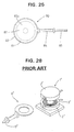
- Non-contact type charging systems for electric automotive vehicles using electromagnetic induction have been developed.
- An example of such charging systems is the one disclosed in Japanese Unexamined Patent Publication No. 5-258962.
- This system is such as shown in FIG. 28 that a secondary coil unit 1' is arranged on a body of an electric automotive vehicle, a primary coil unit 6' connected with a charging power source 5' is set in the secondary coil unit 1' to attain an electromagnetically connected state, and an alternating current is caused to flow in the primary coil unit 6' to generate a power in the secondary coil unit 1'.
- the secondary coil unit 1' of the prior art is constructed by a pair of container-shaped cores 2' each having an open surface and fitted with a secondary coil 3'.
- the cores 2' are opposed to each other such that a gap for the insertion of the primary coil unit 6' is defined between the open surfaces of the cores 2'.
- the secondary coil unit 1' Since two each of the cores 2' and the secondary coils 3' are essential for the construction of the secondary coil unit 1', the secondary coil unit 1' disadvantageously becomes large and heavy. Further, since the primary coil unit 6' is inserted between the identical assemblies of the secondary coil unit 1', it is necessary to simultaneously and properly control gaps between the primary coil unit 6' and the two identical assemblies in order to improve the power transmitting efficiency. Such a gap control is very difficult because it is likely to bring about a situation where the optimization of one gap leads to an improper control of the other gap, and accordingly the power transmitting efficiency cannot be improved.
- an object of the present invention is to provide a connection system and a connection method, which are capable of easily charging an electric automotive vehicle and are suited to charging an electric automotive vehicle at home.
- connection system according to claim 1 and by a connection method according to claim 16.
- Preferred embodiments of the invention are subject of the dependent claims.
- a connection system for charging a battery or drive battery of an electric automotive vehicle used to drive the vehicle comprising a primary coil unit connected or connectable with an external power source and a secondary coil unit connected or connectable with a battery or a load, preferably provided in a vehicle, wherein the primary coil unit can be electromagnetically coupled or connected with the secondary coil unit for inducing a current in the secondary coil unit.
- the primary coil unit is displaceable, preferably in substantially upward and downward directions, so as to conform to the position, preferably a height from the ground of a parking space, of the secondary coil unit.
- the primary coil unit preferably connected with a charging power source, is so provided as to substantially project from a wall surface, in particular arranged at an angle different from 0° or 180°, preferably substantially normal to a parking space, wherein the primary coil is insertable into a receptacle provided in proximity of the secondary coil unit, preferably in a substantially lateral or front or rear surface or surface of the vehicle, in particular as the vehicle approaches the wall surface of the parking space.
- the primary coil unit comprises a primary coil being accommodated in a protection casing and a support base, and wherein preferably the leading end of the protection casing is made displaceable
- bearing holes for bearing the support shaft are formed substantially larger than the support shaft and/or wherein the leading end of the protection casing is made displaceable by loosely fitting the support shaft in the bearing holes.
- a slanted surface is formed at a leading end of the primary coil unit so as to taper the primary coil unit in a coupling or insertion direction.
- a guide slanted surface is formed at a front opening edge of the receptacle into which the primary coil unit is insertable so as to make the opening area larger along a direction of insertion.
- the primary and/or secondary coil units are constructed by winding a coil around a core having preferably only one magnetically open surface, which preferably can be opposed to the magnetically open surface of the opposite core, wherein the primary and secondary coil units are preferably so set that the open surfaces of the respective cores are arranged, preferably laterally slid, to be opposed to each other.
- connection system further comprises a biasing member, preferably provided in connection with the secondary coil unit, in particular at the vehicle, for biasing the primary coil unit and the secondary coil unit so as to attain a specified substantially opposed state.
- a biasing member preferably provided in connection with the secondary coil unit, in particular at the vehicle, for biasing the primary coil unit and the secondary coil unit so as to attain a specified substantially opposed state.
- connection system further comprises a guiding means, preferably a wheel guide means, provided in connection with the primary coil unit, preferably on the ground, for guiding the secondary coil unit, in particular the vehicle, toward the electromagnetical coupling position of the primary and secondary coil units.
- a guiding means preferably a wheel guide means, provided in connection with the primary coil unit, preferably on the ground, for guiding the secondary coil unit, in particular the vehicle, toward the electromagnetical coupling position of the primary and secondary coil units.
- the primary coil unit is provided in a parking space or a parking lot, a garage, a gas station or the like of the vehicle
- the secondary coil unit is provided in a vehicle
- a vehicle position detecting means for detecting that the primary and secondary coil units are in their electromagnetically connectable or couplable positions
- a charging control circuit for exciting the primary coil unit by means of the power source on condition that the vehicle position detecting means detects that the vehicle is in a predetermined or predeterminable position.
- a charging control circuit for controlling the exciting of the primary coil unit comprises a remaining capacity detecting means for detecting a remaining capacity of the battery, and preferably excites the primary coil unit on condition that the remaining capacity detected by the remaining capacity detecting means is equal to or smaller than a predetermined or predeterminable value.
- a display means for displaying a charging or charged state corresponding to the remaining capacity of the battery is provided, preferably in the parking space and/or on the vehicle.
- connection system further comprises an identification code transmitting means provided in connection with the secondary coil unit, in particular provided in the vehicle, and an identification code checking means provided in connection with the primary coil unit, in particular provided in the parking space, for comparing an identification code received from the identification code transmitting means with a prestored identification code, wherein preferably a charging control circuit excites the primary coil unit on condition that the identification codes compared by the identification code checking means agree.
- the secondary coil unit comprises a receptacle for substantially receiving the primary coil unit and the primary coil unit comprises a handle for the insertion of the primary coil unit into the receptacle preferably by hand.
- connection method for charging a battery or drive battery of an electric automotive vehicle used to drive the vehicle comprising the steps of: electromagnetically coupling a primary coil unit connected or connectable with an external power source with a secondary coil unit connected or connectable with a battery and/or a load, and inducing a current from the primary coil unit in the secondary coil unit.
- the electromagnetic coupling step comprises the step of moving the secondary coil unit, in particular by moving the vehicle, to couple the primary and secondary coils unit.
- the electromagnetic coupling step comprises the step of substantially opposing magnetically open surfaces of the primary and secondary coil units, and/or the step of laterally sliding the primary and/or secondary coil unit toward each other.
- an electromagnetic induction apparatus is connected by parking the vehicle in a predetermined position of a parking space to supply a power from a charging power source installed in the parking space to the battery of the vehicle.
- the electromagnetic induction apparatus is connected by a usual action of parking the vehicle in the predetermined position to supply a power from the charging power source installed in the parking space to the battery. Accordingly, unlike the prior art, an operation of fittably connecting the connectors can be dispensed with and the charging can very easily be performed.
- connection system or charging system preferably comprises:
- the charging control circuit preferably comprises a remaining capacity detecting means for detecting a remaining capacity of the battery, and excites the primary coil on condition that the remaining capacity detected by the remaining capacity detecting means is equal to or smaller than a predetermined value.
- the charging is performed when the remaining capacity of the battery is small, and not when the remaining capacity thereof is large. Accordingly, the battery can be charged in proper quantities, obviating the need for worrying about the remaining capacity.
- the charging control circuit preferably comprises a remaining capacity detecting means for detecting a remaining capacity of the battery, and a display means for displaying a charged state corresponding to the remaining capacity of the battery is preferably provided in the parking space. This construction is convenient because the charged state of the battery can be confirmed outside the vehicle.
- an identification code transmitting means is preferably provided in the vehicle, and the charging control circuit excites the primary coil on condition that it receives a specified identification code.
- the charging is started only when the vehicle which transmits the specified identification code is parked. Accordingly, events where the other vehicle is inadvertently charged and the vehicle intruded into the parking space is charged without permission and other undesirable events can securely be prevented.
- a connection system or an electromagnetic connection apparatus provided in a parking space for an electric automotive vehicle for charging a battery of the vehicle, comprising a primary coil unit supported on a wall surface of the parking space and including a primary coil which can be opposed to a secondary coil provided at a front part of the vehicle, wherein the primary coil unit is displaceable upward and downward so as to conform to the height of the secondary coil from the ground of the parking space.
- an electromagnetic connection apparatus used for charging an electric automotive vehicle which is capable of securely establishing an electromagnetic connection when power is supplied to the vehicle.
- the charging of the vehicle can be prepared only by a usual action of parking the vehicle.
- the degree of compression of the suspension spring provided in the vehicle body differs, for example, depending upon the carrying loads of the vehicle, the height of the secondary coil mounted on the vehicle body is expected to slightly vary depending upon the carrying loads.
- Such a change can be compensated by the vertical displacement of the primary coil, with the result that both coils are constantly opposed to each other in a satisfactory manner.
- the electromagnetic connection apparatus preferably comprises a primary coil unit which includes a primary coil connected with a charging power source and is so provided as to project from a wall surface of the parking space, wherein the primary coil unit being insertable into a receptacle provided in the front surface of the vehicle as the vehicle approaches the wall surface of the parking space.
- the primary coil unit is preferably such that the primary coil is accommodated in a protection casing having a support base, and the leading end of the protection casing is preferably made displaceable by supporting the support base on a holder provided at the wall surface of the parking space via an elastic member.
- the leading end of the primary coil unit is displaced, following the position of the front opening of the receptacle of the secondary coil unit. Accordingly, even if the vehicle is parked in a position slightly displaced from the predetermined parking position, the primary coil unit compensates for this displacement so as to be inserted into the secondary coil unit.
- the primary coil unit is preferably such that the primary coil is accommodated in a protection casing having a support base, and the leading end of the protection casing may be made displaceable by rotatably mounting the support base on a holder provided at the wall surface of the parking space via a support shaft and by providing elastic members between the support base and inner surfaces of the holder before and after the support shaft.
- the leading end of the primary coil unit is displaced, following the position of the front opening of the receptacle of the secondary coil unit so that the primary coil unit can securely be inserted into the secondary coil unit. Further, since the primary coil unit is supported on the holder via the support shaft, the primary coil is more stably positioned and has a better durability as compared with the case where it is supported only via the elastic member.
- bearing holes for bearing the support shaft may be formed larger than the support shaft and the leading end of the protection casing may be made displaceable by loosely fitting the support shaft in the bearing holes.
- the primary coil unit can make not only a pivotal movement about the support shaft, but also a pivotal movement in the plane including the support shaft. Accordingly, the primary coil unit can be displaced upward, downward, to the left and to the right while being stably supported by the support shaft. As a result, both coils can more securely be connected.
- Both coils can further more securely be connected by tapering the primary coil unit toward the leading end thereof and by forming a guide slanted surface at the front opening edge of the receptacle of the secondary coil unit.
- a connection system or charging system for an electric automotive vehicle comprises:
- connection or charging system for an electric automotive vehicle which includes a smaller and lighter secondary coil unit mountable on the vehicle and is capable of maintaining a high power transmitting efficiency between the primary and secondary coil units.
- the secondary coil unit can be, as a whole, made smaller and lighter since it is constructed by the single core and the single coil. Further, since only one magnetic gap is formed between the primary and secondary coil units, the gap can easily be controlled. By properly controlling the gap, the power transmitting efficiency can be maintained at a high level.
- the coil units have a flat shape. Since the respective cores are substantially opposed to each other by laterally sliding the secondary coil unit according to the present invention, an insertion path for bringing the secondary coil unit to be opposed to the primary coil unit can be made smaller. This is advantageous in the construction and/or design of the electric automotive vehicle, e.g. since only a reduce frontal surface is required for the connection system.
- the primary coil unit is provided at a parking space for the vehicle
- the secondary coil unit is provided at a front or rear part of the vehicle
- the open surface of the core of the secondary coil unit is laterally slid with respect to the open surface of the core of the primary coil unit to be opposed thereto by parking the vehicle in a predetermined position of the parking space.
- the coil units can be set in their specified electromagnetic connection positions, taking advantage of a usual action of driving the vehicle forward or backward to park it in a predetermined position. Accordingly, the operation for the charging can be simplified.
- the primary coil unit comprises the core, a primary coil and a protection casing having a support base and adapted to accommodate the core and the primary coil, and the leading end of the primary coil unit is made displaceable by supporting the support base on a holder provided at a wall surface of the parking space via an elastic member.
- the leading end of the primary coil unit can be made displaceable so as to conform to the position of the secondary coil unit. Accordingly, even if the vehicle is parked in a position slightly displaced from the predetermined charging position, the primary coil unit is moved to compensate for this displacement, and reaches a position for the electromagnetic connection with the secondary coil unit.
- the primary coil unit comprises the core, a primary coil and a protection casing having a support base and adapted to accommodate the core and the primary coil, the support base is rotatably supported on a holder provided at a wall surface of the parking lot via a support shaft, and the leading end of the primary coil unit is made displaceable by arranging elastic members between the support base and inner surfaces of the holder before and after the support shaft.
- the leading end of the primary coil unit is displaced to conform to the position of the secondary coil unit, with the result that the primary coil unit is securely moved to the position for the electromagnetic connection with the secondary coil unit.
- the primary coil unit is supported on the holder via the support shaft, the primary coil unit is more stably positioned and has a better durability as compared to the case where the primary coil unit is supported only by the elastic members.
- the leading end of the primary coil unit is made displaceable by forming bearing holes for bearing the support shaft larger than the support shaft and loosely fitting the support shaft in the bearing holes.
- the primary coil unit can make not only a pivotal movement about the support shaft, but also a pivotal movement in the plane including the support shaft. Accordingly, the primary coil unit can be displaced upward, downward, to the left and to the right while being stably supported by the support shaft. As a result, both coils can more securely be connected.
- a slanted surface may be formed at the leading end of the primary coil unit so as to taper the primary coil unit toward the leading end thereof, and/or the secondary coil unit may comprise a receptacle for receiving the primary coil unit and a guide slanted surface may be formed at the front opening of the receptacle so as to make the opening area larger along a direction toward the front.
- the charging system further comprises a biasing member provided at the vehicle for biasing the primary coil unit toward the secondary coil unit so as to attain a specified opposed state.
- the specified opposed state e. g. the gap of specified distance can be attained between the coils, thereby establishing a stable and secure electromagnetically connected state.
- the secondary coil unit comprises a receptacle for receiving the primary coil unit and the primary coil unit comprises a handle for the insertion of the primary coil unit into the receptacle by hand.
- the primary coil unit can be gripped by hand to be set in the position for the electromagnetic connection with the secondary coil unit. Accordingly, the overall construction can be considerably simplified and inexpensively manufactured.
- FIGS. 1 to 5 a first embodiment of the invention is described with reference to FIGS. 1 to 5.
- FIG. 1 shows an electric automotive vehicle E being advanced in a parking space.
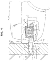
- a primary coil unit 30 partly constructing an electromagnetic induction apparatus projects forward from a wall surface W of the parking space.
- the primary coil unit 30 is such that a substantially flat plate-shaped primary coil 31 formed by winding a wire around a magnetic core 32 e.g. of ferrite is accommodated in a protection casing 33 of, e.g. synthetic resin.
- a support base 34 is integrally or unitarily provided at one end of the protection casing 33.
- a pair of support shafts 35 project from the support base 34 along a lateral direction (vertical direction in FIG. 2).
- the leading end of the protection casing 33 is tapered, forming an arch-shaped surface 33a.
- a holder 36 is embedded in the wall surface W of the parking space, and the support base 34 of the protection casing 33 is inserted into the holder 36.
- Bearing holes 36a for bearing the support shafts 35 are formed in the inner walls of the holder 36 so that the protection casing 33 is pivotally supported along the vertical direction (directions of arrows A of FIG. 3) about the support shafts 35. Since the bearing holes 36a are sufficiently larger than the support shafts 35 so as to support the support shafts 35 with a relatively large play, the leading end of the protection casing 33 makes a pivotal movement along the substantially horizontal direction, i.e. along directions of arrows B of FIG. 2.
- the protection casing 33 is elastically supported along the horizontal direction and projects at an angle different from 0° or 180° to the wall surface W, in particular substantially normally projects in a direction substantially normal to the wall surface W as indicated by solid line in FIG. 2, in particular in a standby or rest position.
- a force acts sideways on the leading end of the protection casing 33 in the solid line state of FIG. 2, the protection casing 33, or the primary coil unit 30 makes a reciprocal pivoting movement substantially along the horizontal direction. Further, as shown in FIG.
- a total of four compression springs 38 are provided before and after the support shafts 35 between the upper and lower surfaces of the support base 34 and the upper and lower inner side walls of the holder 36. Accordingly, the protection casing 33 is elastically supported along the vertical direction and normally projects in the direction normal to the wall surface W as shown in FIG. 3. When a vertically acting force is exerted on the leading end of the protection casing 33 in a solid line state of FIG. 3, the protection casing 33, or the primary coil unit 30 pivots upward and downward.
- a secondary coil unit 10 is provided at a vehicle E, preferably at a front bottom part of the vehicle E.
- the secondary coil unit 10 is such that a substantially flat plate-shaped secondary coil 14 formed by winding a wire around a magnetic core 13 of, e.g. ferrite is arranged at the upper surface of a receptacle 11 for substantially receiving the primary coil unit 30.
- the primary and secondary coils 31, 14 constructing the electromagnetic induction apparatus are brought into an electromagnetically connected state, where preferably the magnetic cores 13, 32 of the coils 31, 14 are substantially coaxially located.
- the receptacle 11 is made of, e.g.
- a guide slanted surface 11a is formed so as to make the area of the opening larger along the direction toward the front. Accordingly, the leading end of the protection casing 33 can easily be guided.
- a shock absorbing material 39 is arranged around the primary coil unit 30 on the wall surface W of the parking space. An impact produced when a front bumper B of the vehicle E comes into contact is absorbed by the shock absorbing material 39.
- a pressure switch 40 is embedded in the shock absorbing material 39. Alternatively a proximity switch may be used. When the vehicle E moves forward to a position where the protection casing 33 of the primary coil unit 30 is completely accommodated in the receptacle 11 and the front bumper B strikes against the shock absorbing material 39, the pressure switch 40 is turned on. This pressure switch 40 or proximity switch functions as a vehicle position detecting means.
- a stop lamp 41 is mounted at an upper part of the wall surface W of the parking space. The stop lamp 41 is turned on when the pressure switch 40 operates.
- an infrared communication device 42 is mounted below the primary coil unit 30.
- the infrared communication device 42 faces an infrared communication device 15 provided at a lower part of the front bumper B of the vehicle E.
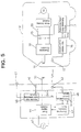
- a power supply circuit 44 provided in the parking space is connected with the primary coil 31.
- the power supply circuit 44 supplies a high frequency current of, e.g. 40 kHz to the primary coil 31 by suitably shaping, e.g. by rectifying and/or switching a commercial power source 45.
- a vehicle position detecting circuit 46 detects that the vehicle E has parked in the specified position upon receipt of a signal from the pressure switch 40. Based on this detection, the detecting circuit 46 turns the stop lamp 41 on and outputs a vehicle detection signal Sev to a charging control circuit 47.
- the charging control circuit 47 Upon receipt of the signal Sev from the vehicle position detecting circuit 46 and a capacity shortage signal Scg from a communication control circuit 48, the charging control circuit 47 actuates the power supply circuit 44 to excite the primary coil 31.
- the communication control circuit 48 is connected with the infrared communication device 42, and receives an information concerning the charging from a capacity detecting circuit via the infrared communication device 15 and a communication control circuit 16 of the vehicle E.
- a charging circuit 18 is connected with the secondary coil 14 to charge a battery 19.
- the charging circuit 18 rectifies an ac current induced in the secondary coil 14 and generates a dc voltage necessary to charge the battery 19.
- a motor driving circuit 21 is connected with the battery 19 via a main switch 20 for driving a drive motor 22 of the vehicle E.
- a remaining capacity detecting circuit 17 receives an information concerning the remaining capacity of the battery 19 via an output line of the battery 19. For example, the remaining capacity detecting circuit 17 estimates the remaining capacity of the battery 19 by adding up consumed power based on the current having flowed in the output line, and outputs the capacity shortage signal Scg when the estimated remaining capacity falls short of a predetermined value.
- the remaining capacity detecting circuit 17 also receives, from the charging circuit 18, an information concerning a charge current flowed into the battery 19; estimates a remaining capacity increasing by the charging based on the received information; and stops outputting the capacity shortage signal Scg when the estimated remaining capacity reaches the predetermined rated value.
- the remaining capacity detecting circuit 17 may directly measure the remaining capacity of the battery 19, e.g. basing upon variations of inductance or capacity of the battery 19.
- the remaining capacity detecting circuit 17 may also measure a temperature of the battery 19 for determining the remaining capacity, at least as a factor for such a determination.
- the vehicle E is slowly advanced toward the wall surface W in the parking space.
- the primary coil unit 30 projecting from the wall surface W is fitted into the receptacle 11 at the front part of the vehicle E.
- the front bumper B of the vehicle E presses the pressure switch 40, thereby operating the same.
- the stop lamp 41 is turned on in response to the signal from the vehicle position detecting circuit 46. If the vehicle E is stopped in this position, the primary coil 31 is coaxially located with the secondary coil 14 in the receptacle 11, being enabled to be electromagnetically connected with the secondary coil 14.
- the vehicle position detecting circuit 46 outputs the vehicle detection signal Sev to the charging control circuit 47.
- the capacity shortage signal Scg is sent to the charging control circuit 47 from the remaining capacity detecting circuit 17 via the infrared communication devices 15, 42, with the result that the power supply circuit 44 operates to excite the primary coil 31.
- a voltage is generated in the secondary coil 14 by an electromagnetic induction phenomenon, and the charging circuit 18 charges the battery 19 of the vehicle E with the generated voltage.
- the output of the capacity shortage signal Scg is stopped.
- the excitation of the primary coil 31 by the charging circuit 18 is stopped, completing the charging.
- the primary and secondary coils 31, 14 are connected only by a usual action of parking the vehicle E in the specified position of the parking space, and power is supplied to the charging circuit 18 of the vehicle E from the commercial power source 45 in the parking space to charge the battery 19, completely obviating need for the engagement of the connectors as in the prior art. Therefore, the charging system according to this embodiment enables a remarkably easy charging and is also very suited to the use at home.
- the second embodiment is similar to the first embodiment except that a display means for displaying a charged state corresponding to the remaining capacity of the battery 19 is additionally provided in the parking space. Accordingly, no repetitive description is given on the identical or similar construction by identifying the same elements by the same reference numerals, and only a different construction is described with reference to FIG. 6.
- a display unit 60 which is controllably turned on by a display control circuit 61.
- the display unit 60 includes a stop lamp 41 and a remaining capacity indicator 62 formed e.g. by vertically arranging a plurality of LEDs.
- a remaining capacity detecting circuit 63 provided in an electric automotive vehicle E constantly detects the remaining capacity of a battery 19 being charged and sends the detection data to the display control unit 61 via infrared communication devices 15, 42 to make a display corresponding to the detected remaining capacity in the capacity indicator 62.
- a display in proportion to the remaining capacity is made in this embodiment: all LEDs of the capacity indicator 62 are turned on when the battery 19 is fully charged, and half the number of LEDs are turned on when the battery 19 is half charged. Such a display is convenient because the remaining capacity of the battery 19 being charged is easily visible.
- the third embodiment is similar to the first embodiment except that the charging is performed only when identification (ID) codes of the vehicle agree. Accordingly, no repetitive description is given on the identical or similar construction by identifying the same elements by the same reference numerals, and only a different construction is described with reference to FIG. 7.
- An electric automotive vehicle E is provided with an ID code transmitting circuit 70 which is connected with a communication control circuit 16.
- an ID code checking circuit 71 which is connected with a communication control circuit 48 and a charging control circuit 47.
- the ID checking circuit 71 Upon recept of a vehicle detection signal Sev from a vehicle position detecting circuit 46, the ID checking circuit 71 sends a signal to the ID transmitting circuit 70 of the vehicle E via infrared communication devices 15, 42, causing the ID transmitting circuit 70 to respond by sending an ID code peculiar to the vehicle E via the infrared communication devices 15, 42. If the received ID code agrees with the code stored in the ID code checking circuit 71, the ID code checking circuit 71 outputs an agreement signal Ssm to the charging control circuit 47.
- the charging control circuit 47 starts the excitation of the primary coil 31 on condition that it received the vehicle detection signal Sev, the capacity shortage signal Scg and the agreement signal Ssm.
- the charging is not started unless the ID code from the vehicle E agrees with the ID code stored in advance in the ID code checking circuit 71. Accordingly, a possibility that the other's car parked in the parking space is charged, or the other's car is intruded into the parking space and charged without permission can securely be prevented.
- the fourth embodiment differs from the first to third embodiments in that the primary and secondary coils 31, 14 are so positioned as to establish an electromagnetic connection after the vehicle E is parked in the parking space.
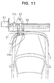
- the fourth embodiment is described with reference to FIGS. 8 to 11.
- a coil positioning apparatus 50 is provided in the wall surface W of the parking space, and a primary coil 31 is supported such that its electromagnetic connection surface faces forward.
- a secondary coil 14 is mounted such that its electromagnetic connection surface substantially faces in a direction toward the wall surface W, e.g. substantially forward as shown in FIG. 10.
- the coil positioning apparatus 50 substantially horizontally moves the primary coil 31 by a so-called ball screw mechanism to a position where it is electromagnetically connectable with a secondary coil 14 by detecting the positional relationship of the primary and secondary coils 31, 14 by sensors 43.
- the ball screw mechanism of the coil positioning apparatus 50 includes a substantially horizontally extending support rail 51, a ball screw 55 provided along the support rail 51, and a support member 52 which is movably supported on the support rail 51 and spirally fitted to the ball screw 55.
- the support rail 51 is such that a substantially horizontally extending slit 51a is formed e.g. in the middle of a plate member and the portions of the plate member above and below the slit 51a construct a pair of rails.
- the slit 51a is preferably formed such that the spacing between the pair of rails widens in a stepwise manner toward the front surface as shown in FIG. 9.
- the support member 52 includes a substantially flat disk--shaped portion for accommodating the primary coil 31, a substantially rectangular beam 52a extending from the back of the disk--shaped portion, and a tubular internally threaded portion 56 provided at the leading end of the rectangular beam 52a so as to be spirally engageable with the ball screw 55.
- An integral assembly of the disk-shaped portion and the rectangular beam 52a has such a vertical cross section as to be fittable in the slit 51a of the support rail 51 in which the width is preferably widened in a stepwise manner toward the front surface.
- the ball screw 55 is so arranged as to face the slit 51a at the back of the support rail 51, and is spirally engaged with the internally threaded portion 56 projecting backward.
- the opposite ends of the ball screw 55 are rotatably supported by bearings 51b projecting backward from the opposite ends of the support rail 51.
- To one end of the ball screw 55 is coupled a drive shaft of a motor 57 fixed to the support rail 51.
- Sensors 43 are embedded in the opposite sides of the disk--shaped portion of the support member 52 with the primary coil 31 therebetween as shown in FIG. 10.
- the sensors 43 operate upon detecting a signal or light from signal or light emitters (43a in FIG. 10) which are provided on the opposite sides of the secondary coil 14 of the vehicle E so as to face the sensors 43.
- signal or light emitters 43a in FIG. 10
- the electro-magnetic connection surfaces of the primary and secondary coils 31, 14 are substantially opposed to each other.
- the signal or light emitters of the vehicle E emit signals or light for a predetermined time measured by, e.g. a timer.
- the coils 31, 14 are positioned by the sensors 43 and the ball screw mechanism as follows.
- the support member 52 is positioned at one end of the support rail 51.
- the motor 57 is stopped when the sensors 43 both operate while the support member 52 is moving toward the other end.
- the coils 31, 14 are held with the electromagnetic surfaces thereof substantially opposed to each other. For example, if the vehicle E is obliquely parked, making it impossible to electromagnetically connect the coils 31, 14, the sensors 43 do not operate while the support member 52 is moving toward the other end. In such a case, the driver is notified that the electromagnetic connection is unattainable by, e.g. activating a buzzer or changing the color of a stop lamp.
- the driver may reattempt to park the vehicle E in the proper charging position.
- the coil positioning apparatus 50 thus constructed is mounted on the wall surface W of the parking space via a shock absorbing material 39, and the support rail 51 slightly projects from the wall surface W.
- the apparatus 50 is mounted at such a height that the primary coil 31 is substantially on a level with the secondary coil 14 of the vehicle E.
- a proximity or pressure switch 40 is embedded in the shock absorbing material 39 so as to detect that the support rail 51 is pressed by the vehicle E.
- a stop lamp 41 is turned on as in the first embodiment and the coil positioning apparatus 50 is activated.
- the vehicle E is slowly advanced in the parking space until a bumper B comes into contact with the support rail 51 projecting from the wall surface W.
- the pressure switch 40 in the shock absorbing material 39 operates, thereby turning the stop lamp 41 on.
- the driver signalled by the stop lamp 41 stops the vehicle E (FIG. 10).
- the secondary coil 14 of the vehicle E is located adjacent to a moving path of the primary coil 31 of the coil positioning apparatus 50.
- the coil positioning apparatus 50 starts operating in response to the operation of the pressure switch 40.
- the motor 57 is driven to move the primary coil 31 at the one end of the support rail 51 toward the other end.
- the motor 57 is stopped to hold the primary and secondary coils 31, 14 in the electromagnetically connectable position (FIG. 11).
- the battery 19 is charged in the same manner as in the first embodiment.
- the driver only needs to bring the bumper B into contact with the coil positioning apparatus 50 while parking the vehicle E. Thereafter, the coil positioning apparatus 50 positions the coils 31, 14 for the electromagnetic connection. Therefore, the charging can be very easily performed regardless of the driving technique of the driver.
- the primary coil 31 may, for example, be moved by a timing belt mechanism 58 as shown in FIG. 12.
- a means for supporting the primary coil 31 may be constructed by a rail 59a and a slider 59b as shown in FIG. 13.
- the sensors 43 are used to detect that the coils 31, 14 are in their electromagnetically connectable positions in this embodiment.
- the position detecting means may, for example, detect a displacement of the coils 31, 14. In such a case, the coils 31, 14 are substantially opposed to each other by moving the primary coil 31 by the detected displacement.
- a coil positioning apparatus 80 which is fixed to the wall surface W in the fourth embodiment, is supported inclinably with respect to the wall surface W in a horizontal plane via elastic support mechanisms 90 so that the coils can automatically be positioned along the lateral direction and automatically be substantially opposed in parallel to each other.
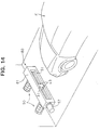
- the fifth embodiment is described with reference to FIGS. 14 to 18.
- the coil positioning apparatus 80 includes a laterally long housing 81 as shown in FIG. 14 or 15.
- a support rail 51, a ball screw 55 and the like are accommodated in the housing 81 so as to render the same function as the coil positioning apparatus 50 described in the fourth embodiment.
- An unillustrated pressure switch 40 is provided in the housing 81 to detect that the support rail 51 provided at the front surface of the housing 81 is pressed. Further, an infrared communication device (not shown) is provided in a specified position of the lower part of the housing 81 to obtain pieces of necessary information such as a charged amount of the vehicle E.
- the housing 81 is mounted on the wall surface W of the parking space via the elastic support mechanisms 90 which include each a support bracket 91 extending from the back surface of the housing 81 and a strut 92 projecting from the wall surface W of the parking space.
- the struts 92 of the mechanisms 90 are placed apart side by side along the horizontal direction by the same distance as the support brackets 91 of the mechanisms 90.
- each strut 92 is substantially U-shaped and separated into two parts: upper and lower parts, and a shaft 94 is mounted through these upper and lower parts and the support bracket 91 disposed between the upper and lower parts.
- Through holes formed in the strut 92 through which the shaft 94 is inserted have the same diameter as the shaft 94, but through holes formed in support bracket 91 are oblong holes so as to permit the support bracket 91 to move along forward and backward directions with respect to the shaft 94.
- the support bracket 91 is pivotally and slidably coupled with the leading end of the strut 92 via the shaft 94.
- the support bracket 91 is also inclinable because the shaft 94 can be inclined in the oblong holes.
- the opposite ends of the shaft 94 are secured by, e.g. clips, nuts or the like.
- the struts 92 and the support brackets 91 coupled as described above are biased in a projecting direction by compression coil springs 93 fitted thereon. Accordingly, the support brackets 91 are securely and stably held in their projected positions, and act as follows. For example, if the vehicle E is obliquely parked, one end of the bumper B comes into contact with one end of the coil positioning apparatus 80. Thus, only the elastic support mechanism 90 at the side pressed by the bumper B slides, and the one at the other side rotates, with the result that the coil positioning apparatus 80 is inclined with respect to the wall surface W along the horizontal plane so that the bumper B of the vehicle E and the coil positioning device 80 are opposed in parallel to each other.
- both elastic support mechanisms 90 make a sliding movement and the shock is absorbed by the compression coil springs 93. Further, since the elastic support mechanisms 90 are inclinable along the forward and backward directions, they are capable of bringing the coil positioning apparatus 80 and the bumper B into close contact by offsetting the inclinations of the coil positioning apparatus 80 and the bumper B along the forward and backward directions.
- the vehicle E is provided with a secondary coil 14 at its front surface.
- the electromagnetic connection surface of the secondary coil 14 is oriented in conformity with a contact surface of the bumper B with the coil positioning apparatus 80. Accordingly, if the coil positioning apparatus 80 and the bumper B are opposed in parallel to each other as described above, the electromagnetic connection surfaces of the coils 31, 14 are opposed in parallel to each other. Further, since the coil positioning apparatus 80 is inclinable along the forward and backward directions as described above, if the contact surface of the bumper B is inclined, the electromagnetic connection surface of the secondary coil 14 may be accordingly inclined.
- the vehicle E is advanced in the parking space to bring the bumper B into contact with the coil positioning apparatus 80 projecting from the wall surface W.
- the vehicle E is stopped when a stop lamp 41 is turned on in response to a pressure switch 40.
- the elastic support mechanisms 90 act to offset the resulting inclination, thereby allowing the bumper B of the vehicle E to face the coil positioning apparatus 80 substantially straight. Accordingly, the driver needs not consider an angle of the vehicle with respect to the coil positioning apparatus 80. Thus any inclination of the vehicle E with respect to the coil positioning apparatus 80 can be compensated for.
- the coil positioning apparatus 80 starts operating in response to the pressure switch 40, thereby guiding the primary coil 31 to a position where it is electromagnetically connectable with the secondary coil 14 in the same manner as in the fourth embodiment for the charging.
- the bumper B of the vehicle E and the coil positioning apparatus 80 face substantially straight each other, the coils 31, 14 can constantly brought to their proper electromagnetically connectable positions. Therefore, the charging can efficiently be performed.
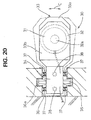
- FIGS. 19 to 23 a sixth embodiment of the invention is described with reference to FIGS. 19 to 23.
- FIG. 19 shows an electric automotive vehicle E being advanced in a parking space.
- a primary coil unit 30 partly constructing an electromagnetic induction apparatus projects forward from a wall surface W of the parking space.
- the primary coil unit 30 is such that a primary coil 31 contained in a core 32 of, e.g. ferrite is accommodated in a protection casing 33 of, e.g. hard synthetic resin.
- the core 32 has a substantially flat circular container-like shape having only one open surface (upper surface) and is formed with a circular column 32a in its center.
- the primary coil 31 is wound around the circular column 32a.
- the open upper surface of the protection casing 33 is covered by a smooth protection film 33b of specified thickness which sealably attaches to the core 32, so that the core 32 and the primary coil 31 are sealed.
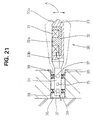
- the secondary coil unit 10 is provided at a front bottom part of the vehicle E.
- the secondary coil unit 10 is constructed by containing a secondary coil 14 in a core 13 of, e.g. ferrite and is provided at an upper part of a receptacle 11 for receiving the primary coil unit 30.
- the core 13 has a shape obtained by inverting the core 32 of the primary coil unit 30, i.e. a flat circular container-like shape having only one open surface (lower surface) and is formed with a circular column 13a in its center. Further, the open lower surface of the core 13 is covered by a smooth protection film 11b of specified thickness which sealably attaches to the core 13, so that the core 13 and the secondary coil 14 are sealed.
- an arch-shaped leaf spring 12 corresponding to a biasing member is provided.
- the leaf spring 12 biases the protection casing 33 upward to bring the primary and secondary coil units 10, 30 into close contact via the two protection films 11b, 33b.
- the coils 31, 14 are electromagnetically connected with the cores 13, 32 coaxially located.
- the other elements are substantially similar or the same as in the previous embodiments.
- the vehicle E is slowly advanced toward the wall surface W in the parking space.
- the primary coil unit 30 projecting from the wall surface W is fitted into the receptacle 11 at the front part of the vehicle E.
- the front bumper B of the vehicle E presses the pressure switch 40, thereby operating the same.
- the stop lamp 41 is turned on in response to the signal from the vehicle position detecting circuit 46. The driver may stop the vehicle E in this position.
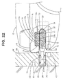
- the open surface of the core 32 of the primary coil unit 30 is laterally slid with respect to the open surface of the core 13 of the secondary coil unit 10, and the core 32 of the primary coil unit 30 comes to be coaxially opposed to the core 13 of the secondary coil unit 10 in the receptacle 11.
- the primary coil unit 30 is biased toward the secondary coil unit 10 by the leaf spring 12 provided in the receptacle 11, with the result that the coils 14, 31 are brought into close contact via the two thin protection films 11b, 33b and electromagnetically connectable with each other. Since the protection films 11b, 33b are both smooth and of specified thickness, the gap between the cores 13, 32 are constantly fixed, ensuring a stable electromagnetically connected state.
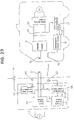
- the vehicle position detecting circuit 46 outputs the vehicle detection signal Sev to the charging control circuit 47.
- the capacity shortage signal Scg is sent to the charging control circuit 47 from the remaining capacity detecting circuit 17 via the infrared communication devices 15, 42, with the result that the power supply circuit 44 operates to excite the primary coil 31.
- a voltage is generated in the secondary coil 14 by an electromagnetic induction phenomenon, and the charging circuit 18 charges the drive battery 19 of the vehicle E with the generated voltage.
- the output of the capacity shortage signal Scg is stopped.
- the excitation of the primary coil 31 by the charging circuit 18 is stopped, completing the charging.
- the primary and secondary coils 31, 14 are connected only by a usual action of parking the vehicle E in the specified position of the parking space, and power is supplied to the charging circuit 18 of the vehicle E from the commercial power source 45 in the parking space to charge the drive battery 19. Therefore, the charging system according to this embodiment enables a remarkably easy charging and is very suited to the use at home.
- the construction of the secondary coil unit 10 by the single core 13 and the single coil 14 makes the secondary coil unit 10 as a whole smaller and lighter. This makes the vehicle lighter, thereby contributing to an improvement in drive performance. Further, since only one magnetic gap between the coil units 10 and 30 is formed between the opposite surfaces of the cores 13 and 32, the gap can easily be controlled. For example, this gap can be held fixed by a simple construction that the primary coil unit 30 is biased toward the secondary coil unit 10 by the leaf spring 12 as in this embodiment. As a result, the power transmitting efficiency between the coil units 10 and 30 can be maintained at a high level. Therefore, generation of heat and power loss can advantageously be suppressed low despite the charging for a long time.
- the secondary coil unit 10 is laterally slid to substantially oppose the cores 13, 32 to each other, an opening used for the insertion of the secondary coil unit 10 can be minimized despite the fact that the cores 13, 32 have a flat shape in order to reduce a magnetic resistance which will acts in the gap. This feature is advantageous in the construction and/or design of the vehicle E.
- the leaf spring 12 is provided at the bottom of the receptacle 11 to bias the primary coil unit 30 toward the secondary coil unit 10, bringing the coil units 10, 30 into close contact. Accordingly, a gap of specified distance is constantly formed between the coil units 10 and 30 via the protection films 11b, 33b. As a result, a stable electromagnetically connected state can advantageously be attained.
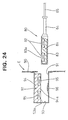
- FIGS. 24 and 25 show an exemplary construction with which a primary coil unit is set in an electric automotive vehicle E by hand.
- a primary coil unit 80 is such that a primary coil 82 is contained in a core 81 having only one surface and the core 81 is accommodated in a protection casing 83. Similar to the first embodiment, the open surface of the core 81 is covered by a smooth protection film 83a.
- a handle 84 for gripping the primary coil unit 81 is integrally or unitarily provided at one end of the protection casing 83.
- a power cable 85 connected with an unillustrated charging power source is drawn through the handle 84.
- an opening 91 is formed in a body 90 of the vehicle E, and a secondary coil unit 92 is provided in the opening 91.
- the secondary coil unit 92 is constructed such that a secondary coil 95 is contained in a core 94 of, e.g. ferrite, and is provided at an upper part of a receptacle 93 for receiving the primary coil unit 80.
- the core 94 has a shape obtained by inverting the core 81 of the primary coil unit 80, i.e. a substantially flat circular container-like shape having only one open surface (lower surface) and is formed with a circular column 94a in its center.
- the open lower surface of the core 94 is covered by a smooth protection film 11b of specified thickness.
- a smooth protection film 11b of specified thickness.
- an arch-shaped leaf spring 96 corresponding to a biasing member is provided.
- the leaf spring 96 biases the primary coil unit 80 upward to bring the primary and secondary coil units 80, 92 into close contact via the two protection films 83a, 93a.
- the coils 82, 95 are electromagnetically connected.
- the primary coil unit 80 when the vehicle E is to be charged, the primary coil unit 80 is inserted into the receptacle 93 of the secondary coil unit 92 by gripping the handle 84. Then, the open surface of the core 81 of the primary coil unit 80 is laterally slid with respect to the open surface of the core 94 of the secondary coil unit 92, and the core 81 of the primary coil unit 80 comes to be coaxially opposed to the core 94 of the secondary coil unit 92 in the receptacle 93.
- the primary coil unit 80 is biased toward the secondary coil unit 92 by the leaf spring 96 provided in the receptacle 92, with the result that the coils 82, 95 are brought into close contact via the two thin protection films 83a, 93a and electromagnetically connectable with each other. Accordingly, similar to the respective foregoing embodiments, the gap between the cores 81 and 94 are constantly fixed, ensuring a stable electromagnetically connected state.
- the primary coil unit may not necessarily constantly project from the wall surface, but may be retracted into the wall surface.
- the front or rear part of the vehicle may be inserted into such a primary coil unit.
- the primary coil unit may be provided with a dust protective cover or a protection cover. Upon detecting a contact or approach of the bumper of the vehicle, this cover is opened to permit the connection with the secondary coil unit.
- FIG. 26 is a perspective view showing an electric automotive vehicle E being advanced into a parking lot equipped with a wheel guide 160 according to an eighth embodiment of the invention.
- the wheel guide 160 includes one, two or more projecting, preferably upstanding substantially L-shaped rails, preferably symmetrically arranged on the ground of the parking lot with their longer sides 160a faced in substantially parallel directions.
- the longer sides 160a are so spaced as to be fittingly located between the left and right wheels of the vehicle E, and have their leading ends bent such that a distance therebetween decreases toward the leading ends.
- Shorter sides may extend in opposite or outward directions from the longer sides 160a and have such a length that the front wheels of the vehicle E can come into contact therewith.
- the vehicle E if the vehicle E is advanced into the parking lot with the longer sides 160a located between the left and right wheels, it stops where the front wheels come into contact with the shorter sides . More specifically, the vehicle E is parked while its orientation and position are determined by the wheel guide 160.
- the pressure sensors 150 detect that the vehicle E has parked along the wheel guide 160, and their detection results are sent to a main controller provided in an external power source unit.
- the vehicle E When the vehicle E is advanced into the parking lot with the longer sides 160a of the wheel guide 160 between the left and right wheels, it is guided with its advancing direction restricted by the longer sides 160a. The vehicle E cannot make any further advance when the front wheels come to positions where they are in contact with the shorter sides or the pressure sensors 150, with the result that a driver can know that the vehicle E is in the charging position.
- a lamp provided at the external power source unit may be turned on. The driver can also know from this lamp that the vehicle E is in the charging position.
- the secondary coil 10 When the vehicle E is stopped in the charging position, the secondary coil 10 is opposed to the primary coil 30.
- the vehicle E can easily be parked in the charging position regardless of the parking technique of the driver.
- the primary coil and the wheel guide may be formed as a single unit and arranged in the parking lot. Further, although the left and right wheels of the vehicle E are guided , the vehicle E may be guided by restricting the opposite side surface of the wheel of the vehicle E at one side by a narrow substantially U-shaped wheel guide 161 as shown in FIG. 26.
- the primary coil unit 10 is substantially coupled or connected with the secondary coil unit 30 provided in the vehicle E.
Abstract
Description
- The present invention relates to a connection system or charging system for charging an electric automotive vehicle and to a connection method.
- The prior art charging system of this type which has been put into practice is constructed as shown in FIG. 27. A
vehicle side connector 2 connected with a battery is provided in a body of an electricautomotive vehicle 1. An externalpower supply connector 3 is connectable with thevehicle side connector 2. Thepower supply connector 3 is provided at the leading end of acable 5 extending from an external power source unit 4 for the charging. The battery is charged by power from the external power source unit 4 via theconnectors - There is an idea that a charging equipment is installed in a parking space of an owner of an electric automotive vehicle at home and that the vehicle being parked is charged by this charging equipment.
- However, with the aforementioned charging system, a driver needs to park the
vehicle 1 in the parking space; get out of thevehicle 1; walk to where there is the charging equipment; take thepower supply connector 3 from the charging equipment; bring thepower supply connector 3 to thevehicle 1 while withdrawing thecable 5; open aconnector cover 1a of the body vehicle; connect thepower supply connector 3 with thevehicle side connector 2; and turn a charging switch on. The above charging operation is fairly cumbersome. Further, since the prior art charging connectors are constructed such that a power supply path is established by fittably connecting terminals, a large resistance acts while the connectors are fitted to each other. Accordingly, a relatively large force is required to connect the connectors. - Furthermore in recent years, non-contact type charging systems for electric automotive vehicles using electromagnetic induction have been developed. An example of such charging systems is the one disclosed in Japanese Unexamined Patent Publication No. 5-258962. This system is such as shown in FIG. 28 that a secondary coil unit 1' is arranged on a body of an electric automotive vehicle, a primary coil unit 6' connected with a charging power source 5' is set in the secondary coil unit 1' to attain an electromagnetically connected state, and an alternating current is caused to flow in the primary coil unit 6' to generate a power in the secondary coil unit 1'.
- Since a considerable amount of power is supplied for a long time to charge an electric automotive vehicle, it is necessary to reduce generation of heat and power loss by improving a power transmitting efficiency between the primary and secondary coil units. Further, in order to make the vehicle lightweight, there is a strong demand for making the secondary coil unit as small and lightweight as possible.
- However, the secondary coil unit 1' of the prior art is constructed by a pair of container-shaped cores 2' each having an open surface and fitted with a secondary coil 3'. The cores 2' are opposed to each other such that a gap for the insertion of the primary coil unit 6' is defined between the open surfaces of the cores 2'.
- Since two each of the cores 2' and the secondary coils 3' are essential for the construction of the secondary coil unit 1', the secondary coil unit 1' disadvantageously becomes large and heavy. Further, since the primary coil unit 6' is inserted between the identical assemblies of the secondary coil unit 1', it is necessary to simultaneously and properly control gaps between the primary coil unit 6' and the two identical assemblies in order to improve the power transmitting efficiency. Such a gap control is very difficult because it is likely to bring about a situation where the optimization of one gap leads to an improper control of the other gap, and accordingly the power transmitting efficiency cannot be improved.
- In view of the above problems, an object of the present invention is to provide a connection system and a connection method, which are capable of easily charging an electric automotive vehicle and are suited to charging an electric automotive vehicle at home.
- This object is solved according to the invention by a connection system according to
claim 1 and by a connection method according toclaim 16. Preferred embodiments of the invention are subject of the dependent claims. - According to the invention, there is provided a connection system for charging a battery or drive battery of an electric automotive vehicle used to drive the vehicle, comprising a primary coil unit connected or connectable with an external power source and a secondary coil unit connected or connectable with a battery or a load, preferably provided in a vehicle, wherein the primary coil unit can be electromagnetically coupled or connected with the secondary coil unit for inducing a current in the secondary coil unit.
- According to a preferred embodiment, the primary coil unit is displaceable, preferably in substantially upward and downward directions, so as to conform to the position, preferably a height from the ground of a parking space, of the secondary coil unit.
- Preferably, the primary coil unit, preferably connected with a charging power source, is so provided as to substantially project from a wall surface, in particular arranged at an angle different from 0° or 180°, preferably substantially normal to a parking space, wherein the primary coil is insertable into a receptacle provided in proximity of the secondary coil unit, preferably in a substantially lateral or front or rear surface or surface of the vehicle, in particular as the vehicle approaches the wall surface of the parking space.
- Further preferably, the primary coil unit comprises a primary coil being accommodated in a protection casing and a support base, and wherein preferably the leading end of the protection casing is made displaceable
- by elastically supporting the support base, in particular on a holder provided at the wall surface of the parking space, via an elastic member, and/or
- by rotatably or pivotably mounting the support base on a holder, in particular provided at the wall surface of the parking space, via at least one support shaft and by preferably providing one or more elastic members between the support base and the holder.
- Further preferably, bearing holes for bearing the support shaft are formed substantially larger than the support shaft and/or wherein the leading end of the protection casing is made displaceable by loosely fitting the support shaft in the bearing holes.
- Still further preferably, a slanted surface is formed at a leading end of the primary coil unit so as to taper the primary coil unit in a coupling or insertion direction.
- Most preferably, a guide slanted surface is formed at a front opening edge of the receptacle into which the primary coil unit is insertable so as to make the opening area larger along a direction of insertion.
- According to a further preferred embodiment, the primary and/or secondary coil units are constructed by winding a coil around a core having preferably only one magnetically open surface, which preferably can be opposed to the magnetically open surface of the opposite core, wherein the primary and secondary coil units are preferably so set that the open surfaces of the respective cores are arranged, preferably laterally slid, to be opposed to each other.
- Preferably, the connection system further comprises a biasing member, preferably provided in connection with the secondary coil unit, in particular at the vehicle, for biasing the primary coil unit and the secondary coil unit so as to attain a specified substantially opposed state.
- Further preferably, the connection system according further comprises a guiding means, preferably a wheel guide means, provided in connection with the primary coil unit, preferably on the ground, for guiding the secondary coil unit, in particular the vehicle, toward the electromagnetical coupling position of the primary and secondary coil units.
- Still further preferably, the primary coil unit is provided in a parking space or a parking lot, a garage, a gas station or the like of the vehicle, the secondary coil unit is provided in a vehicle, and there are further provided a vehicle position detecting means for detecting that the primary and secondary coil units are in their electromagnetically connectable or couplable positions, and a charging control circuit for exciting the primary coil unit by means of the power source on condition that the vehicle position detecting means detects that the vehicle is in a predetermined or predeterminable position.
- Most preferably, a charging control circuit for controlling the exciting of the primary coil unit comprises a remaining capacity detecting means for detecting a remaining capacity of the battery, and preferably excites the primary coil unit on condition that the remaining capacity detected by the remaining capacity detecting means is equal to or smaller than a predetermined or predeterminable value.
- According to still a further preferred embodiment, a display means for displaying a charging or charged state corresponding to the remaining capacity of the battery is provided, preferably in the parking space and/or on the vehicle.
- Preferably, the connection system further comprises an identification code transmitting means provided in connection with the secondary coil unit, in particular provided in the vehicle, and an identification code checking means provided in connection with the primary coil unit, in particular provided in the parking space, for comparing an identification code received from the identification code transmitting means with a prestored identification code, wherein preferably a charging control circuit excites the primary coil unit on condition that the identification codes compared by the identification code checking means agree.
- Further preferably, the secondary coil unit comprises a receptacle for substantially receiving the primary coil unit and the primary coil unit comprises a handle for the insertion of the primary coil unit into the receptacle preferably by hand.
- According to the invention, there is further provided a connection method for charging a battery or drive battery of an electric automotive vehicle used to drive the vehicle, in particular using a connecting system according to one or more of the preceding claims, comprising the steps of: electromagnetically coupling a primary coil unit connected or connectable with an external power source with a secondary coil unit connected or connectable with a battery and/or a load, and inducing a current from the primary coil unit in the secondary coil unit.
- According to a preferred embodiment of the invention, the electromagnetic coupling step comprises the step of moving the secondary coil unit, in particular by moving the vehicle, to couple the primary and secondary coils unit.
- Preferably, the electromagnetic coupling step comprises the step of substantially opposing magnetically open surfaces of the primary and secondary coil units, and/or the step of laterally sliding the primary and/or secondary coil unit toward each other.
- According to still a further preferred embodiment, an electromagnetic induction apparatus is connected by parking the vehicle in a predetermined position of a parking space to supply a power from a charging power source installed in the parking space to the battery of the vehicle.
- With this construction, the electromagnetic induction apparatus is connected by a usual action of parking the vehicle in the predetermined position to supply a power from the charging power source installed in the parking space to the battery. Accordingly, unlike the prior art, an operation of fittably connecting the connectors can be dispensed with and the charging can very easily be performed.
- The specific construction of the connection system or charging system preferably comprises:
- a primary coil provided in a parking space of the vehicle and connected with a charging power source,
- a secondary coil provided in the vehicle and connected with a charging circuit for the battery,
- a vehicle position detecting means for detecting that the primary and secondary coils are in their magnetically connectable positions, and
- a charging control circuit for exciting the primary coil by means of the charging power source on condition that the vehicle position detecting means detects that the vehicle is in a predetermined position. With this construction, the battery can automatically be charged only by parking the vehicle in the predetermined position.
- Preferably, the charging control circuit preferably comprises a remaining capacity detecting means for detecting a remaining capacity of the battery, and excites the primary coil on condition that the remaining capacity detected by the remaining capacity detecting means is equal to or smaller than a predetermined value.
- With this construction, the charging is performed when the remaining capacity of the battery is small, and not when the remaining capacity thereof is large. Accordingly, the battery can be charged in proper quantities, obviating the need for worrying about the remaining capacity.
- Further preferably, the charging control circuit preferably comprises a remaining capacity detecting means for detecting a remaining capacity of the battery, and a display means for displaying a charged state corresponding to the remaining capacity of the battery is preferably provided in the parking space. This construction is convenient because the charged state of the battery can be confirmed outside the vehicle.
- Most preferably, an identification code transmitting means is preferably provided in the vehicle, and the charging control circuit excites the primary coil on condition that it receives a specified identification code.
- With this construction, the charging is started only when the vehicle which transmits the specified identification code is parked. Accordingly, events where the other vehicle is inadvertently charged and the vehicle intruded into the parking space is charged without permission and other undesirable events can securely be prevented.
- According to still a further preferred embodiment, there is provided a connection system or an electromagnetic connection apparatus provided in a parking space for an electric automotive vehicle for charging a battery of the vehicle, comprising a primary coil unit supported on a wall surface of the parking space and including a primary coil which can be opposed to a secondary coil provided at a front part of the vehicle, wherein the primary coil unit is displaceable upward and downward so as to conform to the height of the secondary coil from the ground of the parking space.
- Thus there is provided an electromagnetic connection apparatus used for charging an electric automotive vehicle which is capable of securely establishing an electromagnetic connection when power is supplied to the vehicle.
- With this construction, it is sufficient to advance the vehicle toward the wall surface of the parking space to oppose the secondary coil of the vehicle to the primary coil at the wall surface. In other words, the charging of the vehicle can be prepared only by a usual action of parking the vehicle. In this case, since the degree of compression of the suspension spring provided in the vehicle body differs, for example, depending upon the carrying loads of the vehicle, the height of the secondary coil mounted on the vehicle body is expected to slightly vary depending upon the carrying loads. Such a change can be compensated by the vertical displacement of the primary coil, with the result that both coils are constantly opposed to each other in a satisfactory manner.
- The electromagnetic connection apparatus preferably comprises a primary coil unit which includes a primary coil connected with a charging power source and is so provided as to project from a wall surface of the parking space, wherein the primary coil unit being insertable into a receptacle provided in the front surface of the vehicle as the vehicle approaches the wall surface of the parking space.
- With this construction, it is sufficient to insert the primary coil unit at the wall surface into the receptacle of the secondary coil unit of the vehicle by advancing the vehicle toward the wall surface of the parking space. Further, since the secondary coil is arranged together with the receptacle at the front part of the vehicle, the deposition of mud or the like on the secondary coil while the vehicle is running can be prevented. This prevents an increase of an air gap during the connection of both coils, suppressing a reduction in power transmitting efficiency.
- In the above electromagnetic connection apparatus, the primary coil unit is preferably such that the primary coil is accommodated in a protection casing having a support base, and the leading end of the protection casing is preferably made displaceable by supporting the support base on a holder provided at the wall surface of the parking space via an elastic member.
- With this arrangement, the leading end of the primary coil unit is displaced, following the position of the front opening of the receptacle of the secondary coil unit. Accordingly, even if the vehicle is parked in a position slightly displaced from the predetermined parking position, the primary coil unit compensates for this displacement so as to be inserted into the secondary coil unit.
- Further, the primary coil unit is preferably such that the primary coil is accommodated in a protection casing having a support base, and the leading end of the protection casing may be made displaceable by rotatably mounting the support base on a holder provided at the wall surface of the parking space via a support shaft and by providing elastic members between the support base and inner surfaces of the holder before and after the support shaft.
- With this construction as well, the leading end of the primary coil unit is displaced, following the position of the front opening of the receptacle of the secondary coil unit so that the primary coil unit can securely be inserted into the secondary coil unit. Further, since the primary coil unit is supported on the holder via the support shaft, the primary coil is more stably positioned and has a better durability as compared with the case where it is supported only via the elastic member.
- Further, bearing holes for bearing the support shaft may be formed larger than the support shaft and the leading end of the protection casing may be made displaceable by loosely fitting the support shaft in the bearing holes.
- With this arrangement, the primary coil unit can make not only a pivotal movement about the support shaft, but also a pivotal movement in the plane including the support shaft. Accordingly, the primary coil unit can be displaced upward, downward, to the left and to the right while being stably supported by the support shaft. As a result, both coils can more securely be connected.
- Both coils can further more securely be connected by tapering the primary coil unit toward the leading end thereof and by forming a guide slanted surface at the front opening edge of the receptacle of the secondary coil unit.
- According to a further preferred embodiment of the invention, a connection system or charging system for an electric automotive vehicle comprises:
- a secondary coil unit provided at the vehicle,
- a primary coil unit connected with a charging power source and electromagnetically connectable with the secondary coil unit,
wherein the primary and secondary coil units are each constructed by winding a coil around a core having only one magnetically open surface which can be opposed to the magnetically open surface of the opposite core, and are so set that the open surfaces of the respective cores are laterally slid to be opposed to each other. - Thus there is provided a connection or charging system for an electric automotive vehicle which includes a smaller and lighter secondary coil unit mountable on the vehicle and is capable of maintaining a high power transmitting efficiency between the primary and secondary coil units.
- With this construction, the secondary coil unit can be, as a whole, made smaller and lighter since it is constructed by the single core and the single coil. Further, since only one magnetic gap is formed between the primary and secondary coil units, the gap can easily be controlled. By properly controlling the gap, the power transmitting efficiency can be maintained at a high level.
- Further, in the case of power supply by this kind of electromagnetic induction, it is desirable to maximally enlarge the area of the cores of the coil units opposed to each other to reduce a magnetic resistance. In this respect, it is preferred that the coil units have a flat shape. Since the respective cores are substantially opposed to each other by laterally sliding the secondary coil unit according to the present invention, an insertion path for bringing the secondary coil unit to be opposed to the primary coil unit can be made smaller. This is advantageous in the construction and/or design of the electric automotive vehicle, e.g. since only a reduce frontal surface is required for the connection system.
- Preferably, the primary coil unit is provided at a parking space for the vehicle, the secondary coil unit is provided at a front or rear part of the vehicle, and the open surface of the core of the secondary coil unit is laterally slid with respect to the open surface of the core of the primary coil unit to be opposed thereto by parking the vehicle in a predetermined position of the parking space.
- With this construction, the coil units can be set in their specified electromagnetic connection positions, taking advantage of a usual action of driving the vehicle forward or backward to park it in a predetermined position. Accordingly, the operation for the charging can be simplified.
- Further preferably, the primary coil unit comprises the core, a primary coil and a protection casing having a support base and adapted to accommodate the core and the primary coil, and the leading end of the primary coil unit is made displaceable by supporting the support base on a holder provided at a wall surface of the parking space via an elastic member.
- With this construction, the leading end of the primary coil unit can be made displaceable so as to conform to the position of the secondary coil unit. Accordingly, even if the vehicle is parked in a position slightly displaced from the predetermined charging position, the primary coil unit is moved to compensate for this displacement, and reaches a position for the electromagnetic connection with the secondary coil unit.
- Still further preferably, the primary coil unit comprises the core, a primary coil and a protection casing having a support base and adapted to accommodate the core and the primary coil, the support base is rotatably supported on a holder provided at a wall surface of the parking lot via a support shaft, and the leading end of the primary coil unit is made displaceable by arranging elastic members between the support base and inner surfaces of the holder before and after the support shaft.
- With this construction as well, the leading end of the primary coil unit is displaced to conform to the position of the secondary coil unit, with the result that the primary coil unit is securely moved to the position for the electromagnetic connection with the secondary coil unit. Further, the primary coil unit is supported on the holder via the support shaft, the primary coil unit is more stably positioned and has a better durability as compared to the case where the primary coil unit is supported only by the elastic members.
- Most preferably, the leading end of the primary coil unit is made displaceable by forming bearing holes for bearing the support shaft larger than the support shaft and loosely fitting the support shaft in the bearing holes.
- With this arrangement, the primary coil unit can make not only a pivotal movement about the support shaft, but also a pivotal movement in the plane including the support shaft. Accordingly, the primary coil unit can be displaced upward, downward, to the left and to the right while being stably supported by the support shaft. As a result, both coils can more securely be connected.
- According to still a further preferred embodiment, a slanted surface may be formed at the leading end of the primary coil unit so as to taper the primary coil unit toward the leading end thereof, and/or the secondary coil unit may comprise a receptacle for receiving the primary coil unit and a guide slanted surface may be formed at the front opening of the receptacle so as to make the opening area larger along a direction toward the front. With these arrangements, the coils can more securely be connected.
- Preferably the charging system further comprises a biasing member provided at the vehicle for biasing the primary coil unit toward the secondary coil unit so as to attain a specified opposed state.
- With this construction, since the primary coil unit is biased toward the secondary coil unit by the biasing member, the specified opposed state, e. g. the gap of specified distance can be attained between the coils, thereby establishing a stable and secure electromagnetically connected state.
- Further preferably, the secondary coil unit comprises a receptacle for receiving the primary coil unit and the primary coil unit comprises a handle for the insertion of the primary coil unit into the receptacle by hand.
- With this construction, the primary coil unit can be gripped by hand to be set in the position for the electromagnetic connection with the secondary coil unit. Accordingly, the overall construction can be considerably simplified and inexpensively manufactured.
- These and other objects, features and advantages of the present invention will become more apparent upon a reading of the following detailed description and accompanying drawings in which (same reference numerals denote same or similar elements):
- FIG. 1 is an internal construction diagram of a parking space according to a first embodiment of the invention,
- FIG. 2 is a horizontal section of a primary coil unit according to the first embodiment,
- FIG. 3 is a vertical section of the primary coil unit,
- FIG. 4 is a vertical section of the primary and secondary coil units in their connection positions,
- FIG. 5 is a block diagram of a charging system according to the first embodiment,
- FIG. 6 is a block diagram of a second embodiment of the invention,
- FIG. 7 is a block diagram of a third embodiment of the invention,
- FIG. 8 is a perspective view of a parking space according to a fourth embodiment of the invention,
- FIG. 9 is a vertical section of a primary coil unit according to the fourth embodiment,
- FIG. 10 is a plan view of an electric automotive vehicle parked in the parking space according to the fourth embodiment,
- FIG. 11 is a plan view showing a state where the primary coil is driven to an electromagnetically connectable position with a secondary coil in the fourth embodiment,
- FIG. 12 is a perspective view of another embodiment of a primary coil driving means,
- FIG. 13 is a perspective view of still another embodiment of the primary coil driving means,
- FIG. 14 is a perspective view of a parking space according to a fifth embodiment of the invention,
- FIG. 15 is a plan view of an electric automotive vehicle parked in the parking space according to the fifth embodiment,
- FIG. 16 is a plan view of an electric automotive vehicle obliquely parked in the parking space according to the fifth embodiment,
- FIG. 17 is a plan view showing an electromagnetically connected state in the fifth embodiment,
- FIG. 18 is a side view showing the electromagnetically connected state in the fifth embodiment, and
- FIG. 19 is an internal construction diagram of a parking space according to a sixth embodiment of the invention,
- FIG. 20 is a horizontal section of a primary coil unit according to the sixth embodiment,
- FIG. 21 is a vertical section of the primary coil unit,
- FIG. 22 is a vertical section of the primary and secondary coil units in their connection positions,
- FIG. 23 is a block diagram of a charging system according to the sixth embodiment,
- FIG. 24 is a section of a seventh embodiment of the invention,
- FIG. 25 is a plan view of the primary coil unit according to the seventh embodiment,
- FIG. 26 is a perspective view of a eighth embodiment according to the invention,
- FIG. 27 is a side view of a prior art charging system.
- FIG. 28 is a perspective view of a prior art charging system.
- Hereafter, a first embodiment of the invention is described with reference to FIGS. 1 to 5.
- FIG. 1 shows an electric automotive vehicle E being advanced in a parking space. A
primary coil unit 30 partly constructing an electromagnetic induction apparatus projects forward from a wall surface W of the parking space. As shown in FIGS. 2 and 3, theprimary coil unit 30 is such that a substantially flat plate-shapedprimary coil 31 formed by winding a wire around amagnetic core 32 e.g. of ferrite is accommodated in aprotection casing 33 of, e.g. synthetic resin. Asupport base 34 is integrally or unitarily provided at one end of theprotection casing 33. A pair ofsupport shafts 35 project from thesupport base 34 along a lateral direction (vertical direction in FIG. 2). The leading end of theprotection casing 33 is tapered, forming an arch-shapedsurface 33a. - On the other hand, a
holder 36 is embedded in the wall surface W of the parking space, and thesupport base 34 of theprotection casing 33 is inserted into theholder 36.Bearing holes 36a for bearing thesupport shafts 35 are formed in the inner walls of theholder 36 so that theprotection casing 33 is pivotally supported along the vertical direction (directions of arrows A of FIG. 3) about thesupport shafts 35. Since thebearing holes 36a are sufficiently larger than thesupport shafts 35 so as to support thesupport shafts 35 with a relatively large play, the leading end of theprotection casing 33 makes a pivotal movement along the substantially horizontal direction, i.e. along directions of arrows B of FIG. 2. - As shown in FIG. 2, four compression springs 37 as elastic members are arranged before and after the
support shafts 35 between the opposite side walls of thesupport base 34 and the opposite inner walls of theholder 36. Accordingly, theprotection casing 33 is elastically supported along the horizontal direction and projects at an angle different from 0° or 180° to the wall surface W, in particular substantially normally projects in a direction substantially normal to the wall surface W as indicated by solid line in FIG. 2, in particular in a standby or rest position. When a force acts sideways on the leading end of theprotection casing 33 in the solid line state of FIG. 2, theprotection casing 33, or theprimary coil unit 30 makes a reciprocal pivoting movement substantially along the horizontal direction. Further, as shown in FIG. 3, a total of four compression springs 38 are provided before and after thesupport shafts 35 between the upper and lower surfaces of thesupport base 34 and the upper and lower inner side walls of theholder 36. Accordingly, theprotection casing 33 is elastically supported along the vertical direction and normally projects in the direction normal to the wall surface W as shown in FIG. 3. When a vertically acting force is exerted on the leading end of theprotection casing 33 in a solid line state of FIG. 3, theprotection casing 33, or theprimary coil unit 30 pivots upward and downward. - On the other hand, a
secondary coil unit 10 is provided at a vehicle E, preferably at a front bottom part of the vehicle E. Thesecondary coil unit 10 is such that a substantially flat plate-shapedsecondary coil 14 formed by winding a wire around amagnetic core 13 of, e.g. ferrite is arranged at the upper surface of areceptacle 11 for substantially receiving theprimary coil unit 30. When theprotection casing 33 of theprimary coil 31 is substantially completely received in thereceptacle 11, the primary andsecondary coils magnetic cores coils receptacle 11 is made of, e.g. synthetic resin, and has a flat box shape having an open front surface such that theprotection casing 33 of theprimary coil unit 30 can be accommodated therein through the opening in the front surface of the vehicle. At the opening edge of thereceptacle 11 in the front surface, a guide slantedsurface 11a is formed so as to make the area of the opening larger along the direction toward the front. Accordingly, the leading end of theprotection casing 33 can easily be guided. - A
shock absorbing material 39 is arranged around theprimary coil unit 30 on the wall surface W of the parking space. An impact produced when a front bumper B of the vehicle E comes into contact is absorbed by theshock absorbing material 39. Apressure switch 40 is embedded in theshock absorbing material 39. Alternatively a proximity switch may be used. When the vehicle E moves forward to a position where theprotection casing 33 of theprimary coil unit 30 is completely accommodated in thereceptacle 11 and the front bumper B strikes against theshock absorbing material 39, thepressure switch 40 is turned on. This pressure switch 40 or proximity switch functions as a vehicle position detecting means. Astop lamp 41 is mounted at an upper part of the wall surface W of the parking space. Thestop lamp 41 is turned on when thepressure switch 40 operates. In the wall surface W of the parking space, aninfrared communication device 42 is mounted below theprimary coil unit 30. When the vehicle E is parked in a specified position, theinfrared communication device 42 faces aninfrared communication device 15 provided at a lower part of the front bumper B of the vehicle E. - The electrical construction of the charging system is as shown in FIG. 5. A
power supply circuit 44 provided in the parking space is connected with theprimary coil 31. Thepower supply circuit 44 supplies a high frequency current of, e.g. 40 kHz to theprimary coil 31 by suitably shaping, e.g. by rectifying and/or switching acommercial power source 45. A vehicleposition detecting circuit 46 detects that the vehicle E has parked in the specified position upon receipt of a signal from thepressure switch 40. Based on this detection, the detectingcircuit 46 turns thestop lamp 41 on and outputs a vehicle detection signal Sev to a chargingcontrol circuit 47. Upon receipt of the signal Sev from the vehicleposition detecting circuit 46 and a capacity shortage signal Scg from acommunication control circuit 48, the chargingcontrol circuit 47 actuates thepower supply circuit 44 to excite theprimary coil 31. Thecommunication control circuit 48 is connected with theinfrared communication device 42, and receives an information concerning the charging from a capacity detecting circuit via theinfrared communication device 15 and acommunication control circuit 16 of the vehicle E. - On the other hand, in the vehicle E, a charging
circuit 18 is connected with thesecondary coil 14 to charge abattery 19. The chargingcircuit 18 rectifies an ac current induced in thesecondary coil 14 and generates a dc voltage necessary to charge thebattery 19. A motor driving circuit 21 is connected with thebattery 19 via amain switch 20 for driving a drive motor 22 of the vehicle E. A remainingcapacity detecting circuit 17 receives an information concerning the remaining capacity of thebattery 19 via an output line of thebattery 19. For example, the remainingcapacity detecting circuit 17 estimates the remaining capacity of thebattery 19 by adding up consumed power based on the current having flowed in the output line, and outputs the capacity shortage signal Scg when the estimated remaining capacity falls short of a predetermined value. The remainingcapacity detecting circuit 17 also receives, from the chargingcircuit 18, an information concerning a charge current flowed into thebattery 19; estimates a remaining capacity increasing by the charging based on the received information; and stops outputting the capacity shortage signal Scg when the estimated remaining capacity reaches the predetermined rated value. Alternatively the remainingcapacity detecting circuit 17 may directly measure the remaining capacity of thebattery 19, e.g. basing upon variations of inductance or capacity of thebattery 19. The remainingcapacity detecting circuit 17 may also measure a temperature of thebattery 19 for determining the remaining capacity, at least as a factor for such a determination. - Next, how the vehicle E is charged in this embodiment is described. The vehicle E is slowly advanced toward the wall surface W in the parking space. By bringing the front end of the vehicle E into contact with the
shock absorbing material 39 on the wall surface W, theprimary coil unit 30 projecting from the wall surface W is fitted into thereceptacle 11 at the front part of the vehicle E. When the vehicle E comes to a position where theprimary coil unit 30 is completely fitted into thereceptacle 11, the front bumper B of the vehicle E presses thepressure switch 40, thereby operating the same. Accordingly, thestop lamp 41 is turned on in response to the signal from the vehicleposition detecting circuit 46. If the vehicle E is stopped in this position, theprimary coil 31 is coaxially located with thesecondary coil 14 in thereceptacle 11, being enabled to be electromagnetically connected with thesecondary coil 14. - Simultaneously, the vehicle
position detecting circuit 46 outputs the vehicle detection signal Sev to the chargingcontrol circuit 47. At this time, unless the remaining capacity of thebattery 19 exceeds the predetermined value, the capacity shortage signal Scg is sent to the chargingcontrol circuit 47 from the remainingcapacity detecting circuit 17 via theinfrared communication devices power supply circuit 44 operates to excite theprimary coil 31. As a result, a voltage is generated in thesecondary coil 14 by an electromagnetic induction phenomenon, and the chargingcircuit 18 charges thebattery 19 of the vehicle E with the generated voltage. When the remaining capacity of thebattery 19 reaches the predeterminable or predetermined rated value by the charging, the output of the capacity shortage signal Scg is stopped. Thus, the excitation of theprimary coil 31 by the chargingcircuit 18 is stopped, completing the charging. - According to this embodiment, the primary and
secondary coils circuit 18 of the vehicle E from thecommercial power source 45 in the parking space to charge thebattery 19, completely obviating need for the engagement of the connectors as in the prior art. Therefore, the charging system according to this embodiment enables a remarkably easy charging and is also very suited to the use at home. - The second embodiment is similar to the first embodiment except that a display means for displaying a charged state corresponding to the remaining capacity of the
battery 19 is additionally provided in the parking space. Accordingly, no repetitive description is given on the identical or similar construction by identifying the same elements by the same reference numerals, and only a different construction is described with reference to FIG. 6. - At an upper part of the wall surface W of the parking space, there is provided a
display unit 60 which is controllably turned on by adisplay control circuit 61. Thedisplay unit 60 includes astop lamp 41 and a remainingcapacity indicator 62 formed e.g. by vertically arranging a plurality of LEDs. - A remaining
capacity detecting circuit 63 provided in an electric automotive vehicle E constantly detects the remaining capacity of abattery 19 being charged and sends the detection data to thedisplay control unit 61 viainfrared communication devices capacity indicator 62. In other words, a display in proportion to the remaining capacity is made in this embodiment: all LEDs of thecapacity indicator 62 are turned on when thebattery 19 is fully charged, and half the number of LEDs are turned on when thebattery 19 is half charged. Such a display is convenient because the remaining capacity of thebattery 19 being charged is easily visible. - The third embodiment is similar to the first embodiment except that the charging is performed only when identification (ID) codes of the vehicle agree. Accordingly, no repetitive description is given on the identical or similar construction by identifying the same elements by the same reference numerals, and only a different construction is described with reference to FIG. 7.
- An electric automotive vehicle E is provided with an ID
code transmitting circuit 70 which is connected with acommunication control circuit 16. In a parking space, there is provided an ID code checking circuit 71 which is connected with acommunication control circuit 48 and a chargingcontrol circuit 47. Upon recept of a vehicle detection signal Sev from a vehicleposition detecting circuit 46, the ID checking circuit 71 sends a signal to theID transmitting circuit 70 of the vehicle E viainfrared communication devices ID transmitting circuit 70 to respond by sending an ID code peculiar to the vehicle E via theinfrared communication devices control circuit 47. In this embodiment, the chargingcontrol circuit 47 starts the excitation of theprimary coil 31 on condition that it received the vehicle detection signal Sev, the capacity shortage signal Scg and the agreement signal Ssm. - By constructing the charging system as above, the charging is not started unless the ID code from the vehicle E agrees with the ID code stored in advance in the ID code checking circuit 71. Accordingly, a possibility that the other's car parked in the parking space is charged, or the other's car is intruded into the parking space and charged without permission can securely be prevented.
- The fourth embodiment differs from the first to third embodiments in that the primary and
secondary coils - As shown in FIG. 8, a
coil positioning apparatus 50 is provided in the wall surface W of the parking space, and aprimary coil 31 is supported such that its electromagnetic connection surface faces forward. On the other hand, at the front surface of an electric automotive vehicle E, asecondary coil 14 is mounted such that its electromagnetic connection surface substantially faces in a direction toward the wall surface W, e.g. substantially forward as shown in FIG. 10. - The
coil positioning apparatus 50 substantially horizontally moves theprimary coil 31 by a so-called ball screw mechanism to a position where it is electromagnetically connectable with asecondary coil 14 by detecting the positional relationship of the primary andsecondary coils sensors 43. - The ball screw mechanism of the
coil positioning apparatus 50 includes a substantially horizontally extendingsupport rail 51, aball screw 55 provided along thesupport rail 51, and asupport member 52 which is movably supported on thesupport rail 51 and spirally fitted to theball screw 55. - The
support rail 51 is such that a substantially horizontally extendingslit 51a is formed e.g. in the middle of a plate member and the portions of the plate member above and below theslit 51a construct a pair of rails. Theslit 51a is preferably formed such that the spacing between the pair of rails widens in a stepwise manner toward the front surface as shown in FIG. 9. - The
support member 52 includes a substantially flat disk--shaped portion for accommodating theprimary coil 31, a substantially rectangular beam 52a extending from the back of the disk--shaped portion, and a tubular internally threadedportion 56 provided at the leading end of the rectangular beam 52a so as to be spirally engageable with theball screw 55. An integral assembly of the disk-shaped portion and the rectangular beam 52a has such a vertical cross section as to be fittable in theslit 51a of thesupport rail 51 in which the width is preferably widened in a stepwise manner toward the front surface. In other words, when thesupport member 52 is assembled into thesupport rail 51, it is supported on thesupport rail 51 with the electromagnetic connection surface of theprimary coil 31 facing forward and only the internally threadedportion 56 projects backward. - The ball screw 55 is so arranged as to face the
slit 51a at the back of thesupport rail 51, and is spirally engaged with the internally threadedportion 56 projecting backward. The opposite ends of theball screw 55 are rotatably supported bybearings 51b projecting backward from the opposite ends of thesupport rail 51. To one end of theball screw 55 is coupled a drive shaft of amotor 57 fixed to thesupport rail 51. -
Sensors 43 are embedded in the opposite sides of the disk--shaped portion of thesupport member 52 with theprimary coil 31 therebetween as shown in FIG. 10. Thesensors 43 operate upon detecting a signal or light from signal or light emitters (43a in FIG. 10) which are provided on the opposite sides of thesecondary coil 14 of the vehicle E so as to face thesensors 43. In other words, when the twosensors 43 operate upon facing the signal orlight emitters 43a, the electro-magnetic connection surfaces of the primary andsecondary coils - It should be noted that, when the vehicle E is stopped in the parking position, the signal or light emitters of the vehicle E emit signals or light for a predetermined time measured by, e.g. a timer.
- The
coils sensors 43 and the ball screw mechanism as follows. In an initial state, thesupport member 52 is positioned at one end of thesupport rail 51. When the vehicle E is stopped in the charging position, thesupport member 52 is moved toward the other end of thesupport rail 51. Themotor 57 is stopped when thesensors 43 both operate while thesupport member 52 is moving toward the other end. Then, thecoils coils sensors 43 do not operate while thesupport member 52 is moving toward the other end. In such a case, the driver is notified that the electromagnetic connection is unattainable by, e.g. activating a buzzer or changing the color of a stop lamp. - In the above case, the driver may reattempt to park the vehicle E in the proper charging position.
- The
coil positioning apparatus 50 thus constructed is mounted on the wall surface W of the parking space via ashock absorbing material 39, and thesupport rail 51 slightly projects from the wall surface W. Theapparatus 50 is mounted at such a height that theprimary coil 31 is substantially on a level with thesecondary coil 14 of the vehicle E. Further, a proximity orpressure switch 40 is embedded in theshock absorbing material 39 so as to detect that thesupport rail 51 is pressed by the vehicle E. In accordance with a detection signal of thepressure switch 40, astop lamp 41 is turned on as in the first embodiment and thecoil positioning apparatus 50 is activated. - Since the other construction is similar to the first embodiment, no repetitive description is given thereon by identifying the same elements by the same reference numerals.
- Next, how the vehicle E is charged according to this embodiment is described. The vehicle E is slowly advanced in the parking space until a bumper B comes into contact with the
support rail 51 projecting from the wall surface W. When the bumper B comes into contact with thesupport rail 51, thepressure switch 40 in theshock absorbing material 39 operates, thereby turning thestop lamp 41 on. The driver signalled by thestop lamp 41 stops the vehicle E (FIG. 10). At this stage, thesecondary coil 14 of the vehicle E is located adjacent to a moving path of theprimary coil 31 of thecoil positioning apparatus 50. - Simultaneously, the
coil positioning apparatus 50 starts operating in response to the operation of thepressure switch 40. In other words, themotor 57 is driven to move theprimary coil 31 at the one end of thesupport rail 51 toward the other end. When the primary andsecondary coils sensors 43 operate, themotor 57 is stopped to hold the primary andsecondary coils - Further, since the driver is notified of an improper parking position if the
sensors 43 do not operate, he can park the vehicle E again so that thesensors 43 will operate. - Thereafter, the
battery 19 is charged in the same manner as in the first embodiment. - Thus, according to this embodiment, the driver only needs to bring the bumper B into contact with the
coil positioning apparatus 50 while parking the vehicle E. Thereafter, thecoil positioning apparatus 50 positions thecoils - Although the ball screw mechanism is used as a means for moving the
primary coil 31 in this embodiment, theprimary coil 31 may, for example, be moved by atiming belt mechanism 58 as shown in FIG. 12. Further, instead of thesupport rail 51 of this embodiment, a means for supporting theprimary coil 31 may be constructed by a rail 59a and aslider 59b as shown in FIG. 13. Furthermore, as a position detecting means for detecting the position of thesecondary coil 14, thesensors 43 are used to detect that thecoils coils coils primary coil 31 by the detected displacement. - In the fifth embodiment, a
coil positioning apparatus 80, which is fixed to the wall surface W in the fourth embodiment, is supported inclinably with respect to the wall surface W in a horizontal plane viaelastic support mechanisms 90 so that the coils can automatically be positioned along the lateral direction and automatically be substantially opposed in parallel to each other. Hereafter, the fifth embodiment is described with reference to FIGS. 14 to 18. - The
coil positioning apparatus 80 includes a laterallylong housing 81 as shown in FIG. 14 or 15. Asupport rail 51, aball screw 55 and the like are accommodated in thehousing 81 so as to render the same function as thecoil positioning apparatus 50 described in the fourth embodiment. - An
unillustrated pressure switch 40 is provided in thehousing 81 to detect that thesupport rail 51 provided at the front surface of thehousing 81 is pressed. Further, an infrared communication device (not shown) is provided in a specified position of the lower part of thehousing 81 to obtain pieces of necessary information such as a charged amount of the vehicle E. - The
housing 81 is mounted on the wall surface W of the parking space via theelastic support mechanisms 90 which include each asupport bracket 91 extending from the back surface of thehousing 81 and astrut 92 projecting from the wall surface W of the parking space. Thestruts 92 of themechanisms 90 are placed apart side by side along the horizontal direction by the same distance as thesupport brackets 91 of themechanisms 90. - As shown in FIG. 18, the leading end of each
strut 92 is substantially U-shaped and separated into two parts: upper and lower parts, and ashaft 94 is mounted through these upper and lower parts and thesupport bracket 91 disposed between the upper and lower parts. Through holes formed in thestrut 92 through which theshaft 94 is inserted have the same diameter as theshaft 94, but through holes formed insupport bracket 91 are oblong holes so as to permit thesupport bracket 91 to move along forward and backward directions with respect to theshaft 94. Accordingly, thesupport bracket 91 is pivotally and slidably coupled with the leading end of thestrut 92 via theshaft 94. Thesupport bracket 91 is also inclinable because theshaft 94 can be inclined in the oblong holes. - As shown in FIG. 18, the opposite ends of the
shaft 94 are secured by, e.g. clips, nuts or the like. - The
struts 92 and thesupport brackets 91 coupled as described above are biased in a projecting direction by compression coil springs 93 fitted thereon. Accordingly, thesupport brackets 91 are securely and stably held in their projected positions, and act as follows. For example, if the vehicle E is obliquely parked, one end of the bumper B comes into contact with one end of thecoil positioning apparatus 80. Thus, only theelastic support mechanism 90 at the side pressed by the bumper B slides, and the one at the other side rotates, with the result that thecoil positioning apparatus 80 is inclined with respect to the wall surface W along the horizontal plane so that the bumper B of the vehicle E and thecoil positioning device 80 are opposed in parallel to each other. Further, if the vehicle E is parked straight, thecoil positioning apparatus 80 is equally pressed by the bumper B. Accordingly, bothelastic support mechanisms 90 make a sliding movement and the shock is absorbed by the compression coil springs 93. Further, since theelastic support mechanisms 90 are inclinable along the forward and backward directions, they are capable of bringing thecoil positioning apparatus 80 and the bumper B into close contact by offsetting the inclinations of thecoil positioning apparatus 80 and the bumper B along the forward and backward directions. - On the other hand, the vehicle E is provided with a
secondary coil 14 at its front surface. The electromagnetic connection surface of thesecondary coil 14 is oriented in conformity with a contact surface of the bumper B with thecoil positioning apparatus 80. Accordingly, if thecoil positioning apparatus 80 and the bumper B are opposed in parallel to each other as described above, the electromagnetic connection surfaces of thecoils coil positioning apparatus 80 is inclinable along the forward and backward directions as described above, if the contact surface of the bumper B is inclined, the electromagnetic connection surface of thesecondary coil 14 may be accordingly inclined. - Since the other construction is similar to the fourth embodiment, no repetitive description is given thereon by identifying the same elements by the same reference numerals.
- Next, how the vehicle E is charged according to the fifth embodiment is described. The vehicle E is advanced in the parking space to bring the bumper B into contact with the
coil positioning apparatus 80 projecting from the wall surface W. The vehicle E is stopped when astop lamp 41 is turned on in response to apressure switch 40. At this time, even if the vehicle E comes into contact with thecoil positioning apparatus 80 along an oblique direction, theelastic support mechanisms 90 act to offset the resulting inclination, thereby allowing the bumper B of the vehicle E to face thecoil positioning apparatus 80 substantially straight. Accordingly, the driver needs not consider an angle of the vehicle with respect to thecoil positioning apparatus 80. Thus any inclination of the vehicle E with respect to thecoil positioning apparatus 80 can be compensated for. - Simultaneously, the
coil positioning apparatus 80 starts operating in response to thepressure switch 40, thereby guiding theprimary coil 31 to a position where it is electromagnetically connectable with thesecondary coil 14 in the same manner as in the fourth embodiment for the charging. At this time, since the bumper B of the vehicle E and thecoil positioning apparatus 80 face substantially straight each other, thecoils - The present invention is not limited to the foregoing described and illustrated embodiments. For example, the following embodiments are also embraced by the technical scope of the present invention as defined in the claims. Besides these embodiments, a variety of changes may be made without departing from the spirit and scope of the present invention as defined in the claims.
- (1) Although the
primary coil unit 30 is provided in the wall surface W of the parking space in the first to fourth embodiments, the present invention is not limited to such aprimary coil unit 30. For example, the primary coil may project from the ground of the parking space toward the secondary coil provided at the bottom of the electric automotive vehicle for the electromagnetic connection. Alternatively, the primary coil may be provided at the ceiling, bonnet or trunk lid of the vehicle, and the secondary coil may be hung from the ceiling of the parking space and be lowered for the connection with the primary coil. Even in the case that the primary coil is provided in the wall surface of the parking space, it is not limited to the one which is fixed to project from the wall surface W as in the foregoing embodiments. The primary coil may project from the wall surface when the vehicle is parked in the predetermined position for the connection with the secondary coil provided in the vehicle. Alternatively, the primary coil may be rotatably mounted at the wall surface about a horizontally extending rotatable shaft. Upon detecting that the vehicle has parked in the predetermined position, the primary coil may be rotated upward from a lower position to a position where it is connected with the secondary coil provided at the front bottom surface of the vehicle. - (2) In the foregoing embodiments, the remaining capacity detecting means is provided to automatically charge the
battery 19 in the case that thebattery 19 has a small remaining capacity. However, the present invention is not limited to such a charging system. For example, instead of the remaining capacity detecting means, a charging switch may be provided in an instrument panel in a passenger compartment. Charging is started when the driver operates this charging switch after parking the vehicle in the predetermined position. - (3) The vehicle position detecting means is not limited to the pressure switch embedded in the
shock absorbing material 39 as in the foregoing embodiments, but it may be embodied in various other ways as follows. A deformation gauge is mounted on the surface of the shock absorbing material to detect the deformation of the shock absorbing material caused by the contact of the vehicle. The shock absorbing material is made of conductive rubber, and the compression of the conductive rubber caused by the contact of the vehicle is detected by measuring a conductivity of the conductive rubber. A proximity switch using an infrared or ultrasonic wave, magnetic field, light or the like is provided at the wall surface of the parking space to detect an approach of the vehicle. A photoelectric switch of light blocking type including a plurality of pairs of light emitters and light receptors is provided in a predetermined position of the parking space. When the vehicle is parked in the predetermined position, it blocks the light paths between the light emitters and the light receptors, with the result that the photoelectric switch detects that the vehicle is parked in the predetermined position. An ultrasonic wave transmitter or a light emitter is provided in a specified position of the vehicle, and a corresponding detector is provided in, e.g. the wall surface of the parking space. An alternating current used for the detection is caused to flow in the primary coil, and a phase difference of a voltage/current is measured. The vehicle is detected based on a change in the phase difference of the voltage/current when the vehicle is parked in the predetermined position and the primary and secondary coils are electromagneti-cally connected. - (4) Although the communication is conducted between the vehicle and the parking space via the
infrared communication devices - (5) A vehicle guide for fittably guiding wheels of the vehicle may be provided on the ground of the parking space in order to park the vehicle in the predetermined position of the parking space.
- (6) Although the
support base 34 of theprimary coil unit 30 is supported by the compression springs 38 in the foregoing embodiments, it may be supported by another elastic member such as rubbers or leaf springs. - (7) Besides the
elastic support mechanisms 90 shown in the fifth embodiment, the support mechanism for supporting the primary coil on the wall surface of the parking space may be constructed as follows.- (1) A coil positioning apparatus provided with the primary coil is inclinably supported in one widthwise middle position with respect to the wall surface W of the parking space, i.e. has a seesaw construction, and is biased by a coil spring or the like so as to be balanced. With this arrangement as well, in the case that the vehicle is advanced toward the wall surface in an oblique direction different from a direction perpendicular to the wall surface, the primary coil is inclined by the front part of the vehicle having come into contact with the coil positioning apparatus to be opposed in parallel to the secondary coil. In this case, the support mechanism can advantageously easily be constructed. In the fifth embodiment, the
coil positioning apparatus 80 is inclined by a difference in the lengths of thestruts 92 as the support portions which results from the extension and compression thereof, while offsetting the movement of the vehicle E along the forward and backward directions. Therefore, the coil positioning apparatus can more easily adjust itself to the angle of the parked vehicle E. - (2) Further, a slider or parallel link may be provided at the
struts 92 of the fifth embodiment or at the inclination support portions of the above seesaw construction so as to movably support the primary coil upward and downward in parallel with the wall surface W of the parking space. Alternatively, the base ends of thestruts 92 may be rotatably supported by horizontally extending support shafts so that the leading ends of thestruts 92 are inclinable upward and downward. For example, since the degree of compression of a suspension spring provided in the vehicle body differs depending upon carrying loads of the vehicle, the position of the secondary coil mounted on the vehicle body slightly differs depending on the carrying loads. With the above constructions, even under such a condition, the variation of the position of the secondary coil is offset by moving the primary coil upward or downward. Therefore, the primary and secondary coils are constantly opposed to each other in a satisfactory manner. - (3) Further, the primary coil may be supported by an elastic strut. For example, the primary coil is held at the leading end of a coil spring or a rubber strut projecting from the wall surface so as to be freely movable upward, downward, to the left and to the right. In this case, the inclination mechanism can easily and inexpensively be realized.
- (1) A coil positioning apparatus provided with the primary coil is inclinably supported in one widthwise middle position with respect to the wall surface W of the parking space, i.e. has a seesaw construction, and is biased by a coil spring or the like so as to be balanced. With this arrangement as well, in the case that the vehicle is advanced toward the wall surface in an oblique direction different from a direction perpendicular to the wall surface, the primary coil is inclined by the front part of the vehicle having come into contact with the coil positioning apparatus to be opposed in parallel to the secondary coil. In this case, the support mechanism can advantageously easily be constructed. In the fifth embodiment, the
- (8) Although the motor is driven to move the primary coil along the lateral direction (horizontal direction) in the fourth embodiment, the construction for moving the primary coil may be as follows.
- (1) The primary coil is supported on a substantially horizontally extending support rail, freely movably along a horizontal direction. When the primary coil is excited during the charging, a force acts between the coils to coincide the magnetic centers thereof due to a magnetic flux linking the primary coil with the secondary coil. With the above construction, the primary coil moves in a direction to coincide the magnetic centers of the primary and secondary coils by such a force, thereby enhancing the degree of electromagnetic connection.
- (2) Further, the primary coil may be immovably fixed to the support mechanism. In such a case, the vehicle can be guided such that the coils are brought into their proper electromagnetically connectable positions by providing a mechanism for guiding the wheels of the vehicle on the ground of the parking space. Accordingly, the electromagnetic connection apparatus for the electric automotive vehicle can compactly and inexpensively be realized.
- Hereafter, a sixth embodiment of the invention is described with reference to FIGS. 19 to 23.
- FIG. 19 shows an electric automotive vehicle E being advanced in a parking space. A
primary coil unit 30 partly constructing an electromagnetic induction apparatus projects forward from a wall surface W of the parking space. As shown in FIGS. 20 and 21, theprimary coil unit 30 is such that aprimary coil 31 contained in acore 32 of, e.g. ferrite is accommodated in aprotection casing 33 of, e.g. hard synthetic resin. Thecore 32 has a substantially flat circular container-like shape having only one open surface (upper surface) and is formed with acircular column 32a in its center. Theprimary coil 31 is wound around thecircular column 32a. Further, the open upper surface of theprotection casing 33 is covered by asmooth protection film 33b of specified thickness which sealably attaches to thecore 32, so that thecore 32 and theprimary coil 31 are sealed. - The
secondary coil unit 10 is provided at a front bottom part of the vehicle E. Thesecondary coil unit 10 is constructed by containing asecondary coil 14 in acore 13 of, e.g. ferrite and is provided at an upper part of areceptacle 11 for receiving theprimary coil unit 30. Thecore 13 has a shape obtained by inverting thecore 32 of theprimary coil unit 30, i.e. a flat circular container-like shape having only one open surface (lower surface) and is formed with acircular column 13a in its center. Further, the open lower surface of thecore 13 is covered by asmooth protection film 11b of specified thickness which sealably attaches to thecore 13, so that thecore 13 and thesecondary coil 14 are sealed. At the bottom surface of thereceptacle 11, an arch-shapedleaf spring 12 corresponding to a biasing member is provided. When theprimary coil unit 30 is contained in thereceptacle 11, theleaf spring 12 biases theprotection casing 33 upward to bring the primary andsecondary coil units protection films coils cores - Next, how the vehicle E is charged in this embodiment is described. The vehicle E is slowly advanced toward the wall surface W in the parking space. By bringing the front end of the vehicle E into contact with the
shock absorbing material 39 on the wall surface W, theprimary coil unit 30 projecting from the wall surface W is fitted into thereceptacle 11 at the front part of the vehicle E. When the vehicle E comes to a position where theprimary coil unit 30 is completely fitted into thereceptacle 11, the front bumper B of the vehicle E presses thepressure switch 40, thereby operating the same. Accordingly, thestop lamp 41 is turned on in response to the signal from the vehicleposition detecting circuit 46. The driver may stop the vehicle E in this position. - While the vehicle E is parked as above, the open surface of the
core 32 of theprimary coil unit 30 is laterally slid with respect to the open surface of thecore 13 of thesecondary coil unit 10, and thecore 32 of theprimary coil unit 30 comes to be coaxially opposed to thecore 13 of thesecondary coil unit 10 in thereceptacle 11. In this state, theprimary coil unit 30 is biased toward thesecondary coil unit 10 by theleaf spring 12 provided in thereceptacle 11, with the result that thecoils thin protection films protection films cores - Simultaneously, the vehicle
position detecting circuit 46 outputs the vehicle detection signal Sev to the chargingcontrol circuit 47. At this time, unless the remaining capacity of thebattery 19 exceeds the predetermined value, the capacity shortage signal Scg is sent to the chargingcontrol circuit 47 from the remainingcapacity detecting circuit 17 via theinfrared communication devices power supply circuit 44 operates to excite theprimary coil 31. As a result, a voltage is generated in thesecondary coil 14 by an electromagnetic induction phenomenon, and the chargingcircuit 18 charges thedrive battery 19 of the vehicle E with the generated voltage. When the remaining capacity of thebattery 19 reaches the predetermined rated value by the charging, the output of the capacity shortage signal Scg is stopped. Thus, the excitation of theprimary coil 31 by the chargingcircuit 18 is stopped, completing the charging. - According to this embodiment, the primary and
secondary coils circuit 18 of the vehicle E from thecommercial power source 45 in the parking space to charge thedrive battery 19. Therefore, the charging system according to this embodiment enables a remarkably easy charging and is very suited to the use at home. - The construction of the
secondary coil unit 10 by thesingle core 13 and thesingle coil 14 makes thesecondary coil unit 10 as a whole smaller and lighter. This makes the vehicle lighter, thereby contributing to an improvement in drive performance. Further, since only one magnetic gap between thecoil units cores primary coil unit 30 is biased toward thesecondary coil unit 10 by theleaf spring 12 as in this embodiment. As a result, the power transmitting efficiency between thecoil units secondary coil unit 10 is laterally slid to substantially oppose thecores secondary coil unit 10 can be minimized despite the fact that thecores - In this embodiment, the
leaf spring 12 is provided at the bottom of thereceptacle 11 to bias theprimary coil unit 30 toward thesecondary coil unit 10, bringing thecoil units coil units protection films - FIGS. 24 and 25 show an exemplary construction with which a primary coil unit is set in an electric automotive vehicle E by hand. Similar to the one of the first embodiment, a
primary coil unit 80 is such that aprimary coil 82 is contained in a core 81 having only one surface and thecore 81 is accommodated in aprotection casing 83. Similar to the first embodiment, the open surface of thecore 81 is covered by asmooth protection film 83a. Ahandle 84 for gripping theprimary coil unit 81 is integrally or unitarily provided at one end of theprotection casing 83. Apower cable 85 connected with an unillustrated charging power source is drawn through thehandle 84. - On the other hand, an
opening 91 is formed in abody 90 of the vehicle E, and asecondary coil unit 92 is provided in theopening 91. Similar to the one of the first embodiment, thesecondary coil unit 92 is constructed such that asecondary coil 95 is contained in acore 94 of, e.g. ferrite, and is provided at an upper part of areceptacle 93 for receiving theprimary coil unit 80. Thecore 94 has a shape obtained by inverting thecore 81 of theprimary coil unit 80, i.e. a substantially flat circular container-like shape having only one open surface (lower surface) and is formed with acircular column 94a in its center. Further, the open lower surface of thecore 94 is covered by asmooth protection film 11b of specified thickness. At the bottom surface of thereceptacle 93, an arch-shapedleaf spring 96 corresponding to a biasing member is provided. When theprimary coil unit 80 is contained in thereceptacle 93, theleaf spring 96 biases theprimary coil unit 80 upward to bring the primary andsecondary coil units protection films coils - In this embodiment, when the vehicle E is to be charged, the
primary coil unit 80 is inserted into thereceptacle 93 of thesecondary coil unit 92 by gripping thehandle 84. Then, the open surface of thecore 81 of theprimary coil unit 80 is laterally slid with respect to the open surface of thecore 94 of thesecondary coil unit 92, and thecore 81 of theprimary coil unit 80 comes to be coaxially opposed to thecore 94 of thesecondary coil unit 92 in thereceptacle 93. In this state, theprimary coil unit 80 is biased toward thesecondary coil unit 92 by theleaf spring 96 provided in thereceptacle 92, with the result that thecoils thin protection films cores - The present invention is not limited to the foregoing described and illustrated embodiments. For example, the following embodiments are also embraced by the technical scope of the present invention as defined in the claims. Besides these embodiments, a variety of changes may be made without departing from the spirit and scope of the present invention as defined in the claims.
- The primary coil unit may not necessarily constantly project from the wall surface, but may be retracted into the wall surface. The front or rear part of the vehicle may be inserted into such a primary coil unit. Further, the primary coil unit may be provided with a dust protective cover or a protection cover. Upon detecting a contact or approach of the bumper of the vehicle, this cover is opened to permit the connection with the secondary coil unit.
- FIG. 26 is a perspective view showing an electric automotive vehicle E being advanced into a parking lot equipped with a
wheel guide 160 according to an eighth embodiment of the invention. Thewheel guide 160 includes one, two or more projecting, preferably upstanding substantially L-shaped rails, preferably symmetrically arranged on the ground of the parking lot with their longer sides 160a faced in substantially parallel directions. The longer sides 160a are so spaced as to be fittingly located between the left and right wheels of the vehicle E, and have their leading ends bent such that a distance therebetween decreases toward the leading ends. Shorter sides may extend in opposite or outward directions from the longer sides 160a and have such a length that the front wheels of the vehicle E can come into contact therewith. Accordingly, if the vehicle E is advanced into the parking lot with the longer sides 160a located between the left and right wheels, it stops where the front wheels come into contact with the shorter sides . More specifically, the vehicle E is parked while its orientation and position are determined by thewheel guide 160. - The
pressure sensors 150 detect that the vehicle E has parked along thewheel guide 160, and their detection results are sent to a main controller provided in an external power source unit. - When the vehicle E is advanced into the parking lot with the longer sides 160a of the
wheel guide 160 between the left and right wheels, it is guided with its advancing direction restricted by the longer sides 160a. The vehicle E cannot make any further advance when the front wheels come to positions where they are in contact with the shorter sides or thepressure sensors 150, with the result that a driver can know that the vehicle E is in the charging position. When thepressure sensors 150 are pressed by the front wheels, a lamp provided at the external power source unit may be turned on. The driver can also know from this lamp that the vehicle E is in the charging position. When the vehicle E is stopped in the charging position, thesecondary coil 10 is opposed to theprimary coil 30. - As described above, once that the vehicle E is brought to the wheel guide, the vehicle can easily be parked in the charging position regardless of the parking technique of the driver.
- Although the wheel guide and the primary coil are separately formed and are so arranged as to have a specified positional relationship, the primary coil and the wheel guide may be formed as a single unit and arranged in the parking lot. Further, although the left and right wheels of the vehicle E are guided , the vehicle E may be guided by restricting the opposite side surface of the wheel of the vehicle E at one side by a narrow substantially U-shaped wheel guide 161 as shown in FIG. 26.
- When the wheels of the vehicle E reach the pressure switch(es) 150 the
primary coil unit 10 is substantially coupled or connected with thesecondary coil unit 30 provided in the vehicle E. -
- B
- Bumper
- E
- Electric Automotive Vehicle
- W
- Wall Surface
- 14
- Secondary Coil
- 15,42
- Infrared Communication Device
- 17
- Remaining Capacity Detecting Circuit
- 18
- Charging Circuit
- 30
- Primary Coil Unit
- 31
- Primary Coil
- 39
- Shock Absorbing Material
- 40
- Pressure Switch
- 41
- Stop Lamp
- 44
- Power Source Circuit
- 43
- Sensor
- 46
- Vehicle Position Detecting Circuit
- 47
- Charging Control Circuit
- 50
- Coil Positioning Apparatus
- 51
- Support Rail
- 52
- Support Member
- 55
- Ball Screw
- 57
- Motor
- 70
- Identification Code Transmitting Circuit
- 71
- Identification Code Checking Circuit
- 90
- Elastic Support Mechanism
Claims (18)
- A connection system for charging a battery or drive battery (19) of an electric automotive vehicle (E) used to drive the vehicle (E), comprising a primary coil unit (30) connected or connectable with an external power source (44) and a secondary coil unit (10) connected or connectable with a battery (19) or a load, preferably provided in a vehicle (E), wherein the primary coil unit (30) can be electromagnetically coupled (or connected) with the secondary coil unit (10) for inducing a current in the secondary coil unit (10).
- A connection system according to claim 1, wherein the primary coil unit (30) is displaceable, preferably in substantially upward and downward directions, so as to conform to the position, preferably a height from the ground of a parking space, of the secondary coil unit (10).
- A connection system according to one or more of the preceding claims, wherein the primary coil unit (30) is so provided as to substantially project from a wall surface (W), in particular arranged at an angle different from 0° or 180°, preferably substantially normal to a parking space, wherein the primary coil unit (30) is insertable into a receptacle (11) provided in proximity of the secondary coil unit (10), preferably in a substantially lateral or front or rear surface or surface of the vehicle (E), in particular as the vehicle (E) approaches the wall surface (W) of the parking space.
- A connection system according to one or more of the preceding claims, wherein the primary coil unit (30) comprises a primary coil (31) being accommodated in a protection casing (33) and a support base (34), and wherein preferably the leading end of the protection casing (33) is made displaceableby elastically supporting the support base (34), in particular on a holder (36) provided at the wall surface (W) of the parking space, via an elastic member (37; 38), and/orby rotatably or pivotably mounting the support base (34) on a holder (36), in particular provided at the wall surface (W) of the parking space, via at least one support shaft (35) and by preferably providing one or more elastic members (37; 38) between the support base (34) and the holder (36).
- A connection system according to claim 4, wherein bearing holes (36a) for bearing the support shaft (35) are formed substantially larger than the support shaft (35) and/or wherein the leading end of the protection casing (33) is made displaceable by loosely fitting the support shaft (35) in the bearing holes (36a).
- An electromagnetic connection apparatus according to one or more of the preceding claims, wherein a slanted surface (33a) is formed at a leading end of the primary coil unit (30) so as to taper the primary coil unit (30) in a coupling or insertion direction.
- A connection system according to one or more of the preceding claims and claim 3, wherein a guide slanted surface (11a) is formed at a front opening edge of the receptacle (11) into which the primary coil unit (30) is insertable so as to make the opening area larger along a direction of insertion.
- A connection system according to one or more of the preceding claims, wherein the primary and/or secondary coil units (30; 10) are constructed by winding a coil (31; 14) around a core (32; 13) having preferably only one magnetically open surface, which preferably can be opposed to the magnetically open surface of the opposite core (13; 32), wherein the primary and secondary coil units (30; 10) are preferably so set that the open surfaces of the respective cores (32; 13) are arranged, preferably laterally slid, to be opposed to each other.
- A connection system according to one or more of the preceding claims, further comprising a biasing member (12), preferably provided in connection with the secondary coil unit (10), in particular at the vehicle (E), for biasing the primary coil unit (30) and the secondary coil unit (10) so as to attain a specified substantially opposed state.
- A connection system according to one or more of the preceding claims, further comprising a guiding means (60), preferably a wheel guide means (60), provided in connection with the primary coil unit (30), preferably on the ground, for guiding the secondary coil unit (10), in particular the vehicle (E), toward the electromagnetical coupling position of the primary and secondary coil units (30; 10).
- A connection system according to one or more of the preceding claims, whereinthe primary coil unit (30) is provided in a parking space (or a parking lot, a garage, a gas station or the like) of the vehicle (E),the secondary coil unit (10) is provided in a vehicle (E), andthere are further provided a vehicle position detecting means (40; 43; 43a) for detecting that the primary and secondary coil units (30; 10) are in their electromagnetically connectable (or couplable) positions, anda charging control circuit (47) for exciting the primary coil unit (30) by means of the power source (44) on condition that the vehicle position detecting means (40; 43; 43a) detects that the vehicle (E) is in a predetermined or predeterminable position.
- A connection system according to one or more of the preceding claims, wherein a charging control circuit (47) for controlling the exciting of the primary coil unit (30) comprises a remaining capacity detecting means (63) for detecting a remaining capacity of the battery (19), and preferably excites the primary coil unit (30) on condition that the remaining capacity detected by the remaining capacity detecting means (63) is equal to or smaller than a predetermined or predeterminable value.
- A connection system according to claim 12, wherein a display means (62) for displaying a charging or charged state corresponding to the remaining capacity of the battery (19) is provided, preferably in the parking space and/or on the vehicle (E).
- A connection system according to one or more of the preceding claims, further comprising an identification code transmitting means (70) provided in connection with the secondary coil unit (10), in particular provided in the vehicle (E), and an identification code checking means (71) provided in connection with the primary coil unit (30), in particular provided in the parking space, for comparing an identification code received from the identification code transmitting means (70) with a prestored identification code, wherein preferably a charging control circuit (47) excites the primary coil unit (30) on condition that the identification codes compared by the identification code checking means (71) agree.
- A connection system according to one or more of the preceding claims, wherein the secondary coil unit (10) comprises a receptacle (11) for substantially receiving the primary coil unit (10) and the primary coil unit (10) comprises a handle (84) for the insertion of the primary coil unit (10) into the receptacle (11) preferably by hand.
- A connection method for charging a battery or drive battery (19) of an electric automotive vehicle (E) used to drive the vehicle (E), in particular using a connecting system according to one or more of the preceding claims, comprising the steps of:electromagnetically coupling a primary coil unit (30) connected or connectable with an external power source (44) with a secondary coil unit (10) connected or connectable with a battery (19) and/or a load, andinducing a current from the primary coil unit (30) in the secondary coil unit (10).
- A connection method according to claim 16, wherein the electromagnetic coupling step comprises the step of moving the secondary coil unit (10), in particular by moving the vehicle (E), to couple the primary and secondary coils unit (30, 10).
- A connection method according to claim 16 or 17, wherein the electromagnetic coupling step comprises the step of substantially opposing magnetically open surfaces of the primary and secondary coil units (30, 10), and/or the step of laterally sliding the primary and/or secondary coil unit (30; 10) toward each other.
Priority Applications (3)
| Application Number | Priority Date | Filing Date | Title |
|---|---|---|---|
| EP97101385A EP0788211B1 (en) | 1996-01-30 | 1997-01-29 | A connection system and a connection method |
| DE69714879T DE69714879T2 (en) | 1996-01-30 | 1997-01-29 | Connection system with associated procedure |
| US08/791,109 US5850135A (en) | 1996-01-30 | 1997-01-30 | Connecting system and a connection method |
Applications Claiming Priority (13)
| Application Number | Priority Date | Filing Date | Title |
|---|---|---|---|
| JP14032/96 | 1996-01-30 | ||
| JP8014032A JPH09213378A (en) | 1996-01-30 | 1996-01-30 | Charge system for electric vehicle |
| JP1403296 | 1996-01-30 | ||
| JP1748696 | 1996-02-02 | ||
| JP17486/96 | 1996-02-02 | ||
| JP01748696A JP3586955B2 (en) | 1996-02-02 | 1996-02-02 | Electric vehicle charging system |
| JP81750/96 | 1996-04-03 | ||
| JP08175096A JP3772997B2 (en) | 1995-07-31 | 1996-04-03 | Electric vehicle charging system and electromagnetic coupling device for electric vehicle charging |
| JP8175096 | 1996-04-03 | ||
| JP8192187A JPH09102429A (en) | 1995-07-31 | 1996-07-22 | Charging device for electric automobile |
| JP192187/96 | 1996-07-22 | ||
| JP19218796 | 1996-07-22 | ||
| EP97101385A EP0788211B1 (en) | 1996-01-30 | 1997-01-29 | A connection system and a connection method |
Publications (3)
| Publication Number | Publication Date |
|---|---|
| EP0788211A2 true EP0788211A2 (en) | 1997-08-06 |
| EP0788211A3 EP0788211A3 (en) | 1998-02-04 |
| EP0788211B1 EP0788211B1 (en) | 2002-08-28 |
Family
ID=58463524
Family Applications (1)
| Application Number | Title | Priority Date | Filing Date |
|---|---|---|---|
| EP97101385A Expired - Lifetime EP0788211B1 (en) | 1996-01-30 | 1997-01-29 | A connection system and a connection method |
Country Status (3)
| Country | Link |
|---|---|
| US (1) | US5850135A (en) |
| EP (1) | EP0788211B1 (en) |
| DE (1) | DE69714879T2 (en) |
Cited By (16)
| Publication number | Priority date | Publication date | Assignee | Title |
|---|---|---|---|---|
| EP0921607A2 (en) * | 1997-11-21 | 1999-06-09 | Miltronik GmbH & Co. KG | Connector to transfer data between an electrical voltage source and data processing device |
| EP1205340A1 (en) * | 2000-11-10 | 2002-05-15 | Adrian Robert Mould | Electric vehicle charging station |
| EP1213818A1 (en) * | 1998-03-24 | 2002-06-12 | Seiko Epson Corporation | Electronic device method, method of controlling electronic device, method of estimating charge in rechargeable battery, and method of charging rechargeable battery |
| FR2828589A1 (en) * | 2001-08-07 | 2003-02-14 | France Telecom | Vehicle battery station electrical recharging having vehicle/vehicle station with pluggable connectors with connectors parallel plane placed and having play up to 20 cm. |
| FR2828665A1 (en) * | 2001-08-09 | 2003-02-21 | Honda Motor Co Ltd | Battery charging station for an electric motor assisted bicycle, use parking section which holds front wheel so that secondary contacts on wheel forks engage with primary contacts in parking section |
| CN101764434A (en) * | 2008-12-22 | 2010-06-30 | 爱信艾达株式会社 | Devices, methods, and programs that provide vehicle guidance for power reception |
| CN102039826A (en) * | 2009-10-09 | 2011-05-04 | 周良勇 | Guardrail type power supply circuit for charging electric automobiles or providing driving electricity for electric automobiles |
| WO2011110645A3 (en) * | 2010-03-12 | 2012-06-07 | Leopold Kostal Gmbh & Co Kg | Transmission system for charging the traction batteries of an electrically driven motor vehicle |
| CN102810898A (en) * | 2011-05-31 | 2012-12-05 | 通用电气公司 | System and method for contactless power transfer in portable image detectors |
| CN103563217A (en) * | 2011-05-27 | 2014-02-05 | 日产自动车株式会社 | Non-contact power supply device, vehicle, and non-contact power supply system |
| CN103563216A (en) * | 2011-05-27 | 2014-02-05 | 日产自动车株式会社 | Contactless electricity supply device |
| CN103703650A (en) * | 2011-07-22 | 2014-04-02 | 奥迪股份公司 | Method for charging a traction battery, device for transmitting energy to an electric vehicle and motor vehicle |
| DE102010027670B4 (en) | 2010-07-20 | 2018-10-11 | Siemens Aktiengesellschaft | Device and method for connecting an electrical energy storage device to a charging station |
| WO2019060747A3 (en) * | 2017-09-22 | 2019-05-02 | Locus Robotics Corp. | Robot charging station protective member |
| US10906419B2 (en) | 2016-04-01 | 2021-02-02 | Locus Robotics Corp. | Electrical charging system for a robot |
| WO2021219839A1 (en) * | 2020-04-30 | 2021-11-04 | INSTATE GmbH | Kerbstone module, kerbstone module group, charging station, and method for operating apparatuses of this kind |
Families Citing this family (138)
| Publication number | Priority date | Publication date | Assignee | Title |
|---|---|---|---|---|
| JPH10322921A (en) * | 1997-05-15 | 1998-12-04 | Sumitomo Wiring Syst Ltd | Magnetic coupling device for electric vehicle charging |
| JP3786392B2 (en) * | 1998-09-09 | 2006-06-14 | 本田技研工業株式会社 | Electric vehicle charging device |
| JP2001110659A (en) * | 1999-10-05 | 2001-04-20 | Toyota Autom Loom Works Ltd | Receptacle for electrical charge for charging |
| US9425638B2 (en) | 1999-11-01 | 2016-08-23 | Anthony Sabo | Alignment independent and self-aligning inductive power transfer system |
| JP2001167959A (en) * | 1999-12-10 | 2001-06-22 | Toyota Autom Loom Works Ltd | Electromagnetic induction type feeding charger and electromagnetic induction type charger |
| US6619342B2 (en) | 2001-05-11 | 2003-09-16 | General Hydrogen Corporation | Wheel stop service port |
| US6817879B2 (en) * | 2001-11-26 | 2004-11-16 | General Hydrogen Corporation | Service port configurations |
| US6691749B2 (en) | 2002-01-10 | 2004-02-17 | General Hydrogen Corporation | Service coupling |
| US6722903B2 (en) | 2002-01-10 | 2004-04-20 | General Hydrogen Corporation | Service plug configuration |
| US7023177B1 (en) * | 2002-11-08 | 2006-04-04 | Amigo Mobility International, Inc. | Rechargeable electric battery powered vehicle for the physically challenged and charge station system, and methods of making and assembling the same |
| US20060273756A1 (en) * | 2005-06-06 | 2006-12-07 | Bowling David A | Opportunity charging system for battery powered mining equipment |
| JP4162026B2 (en) * | 2006-09-29 | 2008-10-08 | トヨタ自動車株式会社 | Vehicle charging system, vehicle charging device and electric vehicle |
| US20070170886A1 (en) * | 2006-10-03 | 2007-07-26 | Plishner Paul J | Vehicle equipped for providing solar electric power for off-vehicle use and systems in support thereof |
| US7849250B2 (en) | 2006-10-31 | 2010-12-07 | Sonosite, Inc. | Docking station with hierarchal battery management for use with portable medical equipment |
| US20070124036A1 (en) * | 2006-11-06 | 2007-05-31 | Plishner Paul J | Rail vehicle or other path-constrained vehicle equipped for providing solar electric power for off-vehicle use, and systems in support thereof |
| DE102006053682B4 (en) * | 2006-11-13 | 2020-04-02 | Sew-Eurodrive Gmbh & Co Kg | Consumer and contactless supply system |
| US20080111519A1 (en) * | 2006-11-13 | 2008-05-15 | Vasilantone Michael M | Hybrid automotive vehicle with closed-circuit battery charging |
| US20080221746A1 (en) * | 2007-03-05 | 2008-09-11 | Plishner Paul J | System for providing or receiving electric power from a parked vehicle |
| US8307967B2 (en) | 2007-07-04 | 2012-11-13 | Satyajit Patwardhan | Widely deployable charging system for vehicles |
| JP4788693B2 (en) * | 2007-09-26 | 2011-10-05 | セイコーエプソン株式会社 | Structure |
| JP4600454B2 (en) * | 2007-09-26 | 2010-12-15 | セイコーエプソン株式会社 | Power transmission control device, power transmission device, non-contact power transmission system, secondary coil positioning method |
| CN101809842A (en) * | 2007-09-27 | 2010-08-18 | 松下电器产业株式会社 | Electronic device, recharger and recharging system |
| KR101437975B1 (en) * | 2007-12-06 | 2014-09-05 | 엘지전자 주식회사 | Contactless charging apparatus having charging state display function and charging method using the same |
| US8072182B2 (en) * | 2008-01-25 | 2011-12-06 | Vasilantone Michael M | Hybrid automotive vehicle with closed-circuit, inductance battery charging |
| JP5698121B2 (en) * | 2008-05-13 | 2015-04-08 | スミス・アンド・ネフュー・オルソペディクス・アーゲー | Oxidation resistant high crosslink UHMWPE |
| US8497657B2 (en) * | 2008-06-27 | 2013-07-30 | Microsoft Corporation | Docking station for electronic device |
| JP4868077B2 (en) * | 2008-09-25 | 2012-02-01 | トヨタ自動車株式会社 | Power feeding system and electric vehicle |
| ES2779011T3 (en) | 2008-11-07 | 2020-08-13 | Toyota Motor Co Ltd | Power supply system for vehicles and electric traction vehicle |
| JP5432283B2 (en) | 2008-12-12 | 2014-03-05 | ハンリム ポステック カンパニー リミテッド | Jig for manufacturing contactless power receiver and receiver core |
| EP2199141B1 (en) * | 2008-12-22 | 2016-06-15 | Aisin Aw Co., Ltd. | Guidance device for charging vehicle battery |
| US20100201309A1 (en) * | 2009-02-10 | 2010-08-12 | Meek Ivan C | Systems and methods for coupling a vehicle to an external grid and/or network |
| JP5258048B2 (en) * | 2009-02-19 | 2013-08-07 | トヨタ自動車株式会社 | Garage equipment control system and building |
| US8398408B1 (en) * | 2009-02-25 | 2013-03-19 | Sonosite, Inc. | Charging station for cordless ultrasound cart |
| US8033349B2 (en) | 2009-03-12 | 2011-10-11 | Ford Global Technologies, Inc. | Auto-seek electrical connection for a plug-in hybrid electric vehicle |
| DE102009019125B4 (en) | 2009-04-29 | 2021-10-07 | Sew-Eurodrive Gmbh & Co Kg | System for electrically charging an energy store of an electrically operable vehicle and method for operating a system |
| DE102009023409A1 (en) * | 2009-05-29 | 2010-12-09 | Rohde & Schwarz Gmbh & Co. Kg | System for transferring electrical energy between primary docking module and secondary transformer unit in vehicle, has secondary transformer unit located at bow or tail of vehicle |
| JP5018830B2 (en) * | 2009-06-11 | 2012-09-05 | 日産自動車株式会社 | Charging port lid opening / closing structure |
| JP5320184B2 (en) * | 2009-06-26 | 2013-10-23 | 三菱重工業株式会社 | Wireless power transmission system |
| DE102009033237A1 (en) | 2009-07-14 | 2011-01-20 | Conductix-Wampfler Ag | Device for inductive transmission of electrical energy |
| EP2454119A2 (en) | 2009-07-15 | 2012-05-23 | Conductix-Wampfler AG | System for inductively charging vehicles, comprising an electronic positioning aid |
| JP5316278B2 (en) * | 2009-07-17 | 2013-10-16 | 日産自動車株式会社 | Vehicle charging port structure |
| USD611898S1 (en) | 2009-07-17 | 2010-03-16 | Lin Wei Yang | Induction charger |
| USD611899S1 (en) | 2009-07-31 | 2010-03-16 | Lin Wei Yang | Induction charger |
| USD611900S1 (en) | 2009-07-31 | 2010-03-16 | Lin Wei Yang | Induction charger |
| JP5525804B2 (en) * | 2009-12-03 | 2014-06-18 | 現代自動車株式会社 | Primary coil raising type non-contact charging device |
| CN104709105B (en) * | 2010-01-05 | 2017-04-12 | 捷通国际有限公司 | Inductive charging system for electric vehicle |
| JP2011160505A (en) * | 2010-01-29 | 2011-08-18 | Sony Corp | Wireless charging apparatus and wireless charging system |
| JP2011188733A (en) * | 2010-02-12 | 2011-09-22 | Semiconductor Energy Lab Co Ltd | Moving object, and system and method for wireless power feeding |
| US20110221387A1 (en) * | 2010-03-09 | 2011-09-15 | Robert Louis Steigerwald | System and method for charging an energy storage system for an electric or hybrid-electric vehicle |
| JP5051257B2 (en) | 2010-03-16 | 2012-10-17 | トヨタ自動車株式会社 | vehicle |
| US8674550B2 (en) | 2010-03-25 | 2014-03-18 | General Electric Company | Contactless power transfer system and method |
| JP5408343B2 (en) | 2010-04-21 | 2014-02-05 | トヨタ自動車株式会社 | Vehicle parking assist device and electric vehicle including the same |
| US20110302078A1 (en) | 2010-06-02 | 2011-12-08 | Bryan Marc Failing | Managing an energy transfer between a vehicle and an energy transfer system |
| DE102010025951A1 (en) * | 2010-07-02 | 2012-01-05 | Paul Vahle Gmbh & Co. Kg | Charging station for system for inductively charging vehicle battery, has primary coil arrangement oscillating and/or hanging on device, building or garage and mounted and freely oscillating around axles |
| US20120025758A1 (en) * | 2010-07-28 | 2012-02-02 | General Electric Company | Contactless power transfer system |
| US9552920B2 (en) * | 2010-07-28 | 2017-01-24 | General Electric Company | Contactless power transfer system |
| US8256807B2 (en) | 2010-08-23 | 2012-09-04 | Ford Global Technologies, Llc | In-bumper storage tray for automotive vehicle |
| US8356852B2 (en) | 2010-09-22 | 2013-01-22 | Ford Global Technologies, Llc | Automotive vehicle body closure with storage compartment |
| US20110163141A1 (en) * | 2010-10-27 | 2011-07-07 | Ford Global Technologies, Llc | Apparatus for On-Board Storage of Electric Vehicle Charging Cord |
| KR101318848B1 (en) | 2010-12-01 | 2013-10-17 | 도요타 지도샤(주) | Wireless power feeding apparatus, vehicle, and method of controlling wireless power feeding system |
| DE102010054470A1 (en) | 2010-12-14 | 2012-06-14 | Conductix-Wampfler Ag | Device for inductive transmission of electrical energy |
| CN103262387B (en) | 2010-12-24 | 2016-08-17 | 丰田自动车株式会社 | Non-contact charger systems and method, vehicle and non-contact charge managing device |
| CN102097840B (en) * | 2010-12-31 | 2013-12-11 | 云南昆船数码科技有限公司 | Charging adaptive tray device for electromobile |
| WO2012111127A1 (en) * | 2011-02-17 | 2012-08-23 | パイオニア株式会社 | Charge control device and method, charging system, association method, and computer program |
| JP5834463B2 (en) | 2011-04-21 | 2015-12-24 | 日産自動車株式会社 | Torque control device and non-contact charging system |
| JP5472532B2 (en) * | 2011-05-12 | 2014-04-16 | トヨタ自動車株式会社 | vehicle |
| JP5793963B2 (en) | 2011-05-27 | 2015-10-14 | 日産自動車株式会社 | Non-contact power feeding device |
| US9000721B2 (en) * | 2011-06-29 | 2015-04-07 | General Electric Company | Systems and methods for charging |
| JP5839039B2 (en) * | 2011-09-13 | 2016-01-06 | 株式会社Ihi | Mobile vehicle power supply system |
| EP2739501B1 (en) * | 2011-10-12 | 2020-07-01 | Valeo Siemens eAutomotive Germany GmbH | Charging station |
| US8977200B2 (en) * | 2011-11-14 | 2015-03-10 | Panasonic Intellectual Property Management Co., Ltd. | Communication device performing medium detection by near field communication, external device, and external medium communication system |
| JP6024106B2 (en) | 2011-12-27 | 2016-11-09 | 株式会社Ihi | Transfer device and mobile vehicle |
| US9354748B2 (en) | 2012-02-13 | 2016-05-31 | Microsoft Technology Licensing, Llc | Optical stylus interaction |
| US20130221917A1 (en) * | 2012-02-29 | 2013-08-29 | Sabic Innovative Plastics Ip B.V. | Energy Absorbing System for Electric Vehicle Charging Station and Methods for Making and Using the Same |
| US9870066B2 (en) | 2012-03-02 | 2018-01-16 | Microsoft Technology Licensing, Llc | Method of manufacturing an input device |
| US9134807B2 (en) | 2012-03-02 | 2015-09-15 | Microsoft Technology Licensing, Llc | Pressure sensitive key normalization |
| US9075566B2 (en) | 2012-03-02 | 2015-07-07 | Microsoft Technoogy Licensing, LLC | Flexible hinge spine |
| US8873227B2 (en) | 2012-03-02 | 2014-10-28 | Microsoft Corporation | Flexible hinge support layer |
| US9130359B2 (en) | 2012-03-06 | 2015-09-08 | Sabic Global Technologies B.V. | Energy absorbing system for electric vehicle charging station and methods for making and using the same |
| US8979110B2 (en) * | 2012-03-16 | 2015-03-17 | Specialized Bicycle Components, Inc. | Bicycle with battery mount |
| US9796280B2 (en) | 2012-03-23 | 2017-10-24 | Hevo Inc. | Systems and mobile application for electric wireless charging stations |
| FR2989947B1 (en) * | 2012-04-26 | 2014-05-09 | Delachaux Sa | CONNECTION SYSTEM FOR CHARGING AN ELECTRIC VEHICLE |
| US9494631B2 (en) * | 2012-05-04 | 2016-11-15 | Det International Holding Limited | Intelligent current analysis for resonant converters |
| US20130300590A1 (en) | 2012-05-14 | 2013-11-14 | Paul Henry Dietz | Audio Feedback |
| US9467002B2 (en) | 2012-07-19 | 2016-10-11 | Ford Global Technologies, Llc | Vehicle charging system |
| US10773596B2 (en) | 2012-07-19 | 2020-09-15 | Ford Global Technologies, Llc | Vehicle battery charging system and method |
| US20150229156A1 (en) * | 2012-08-08 | 2015-08-13 | Panasonic Intellectual Property Management Co.,Ltd | Wireless charging device, program therefor, and automobile utilizing same |
| US8964379B2 (en) | 2012-08-20 | 2015-02-24 | Microsoft Corporation | Switchable magnetic lock |
| WO2014029439A1 (en) | 2012-08-23 | 2014-02-27 | Siemens Aktiengesellschaft | Charging device for inductive charging |
| US9908426B2 (en) | 2012-09-27 | 2018-03-06 | Tdk Corporation | Vehicle and mobile body system |
| JP6119172B2 (en) | 2012-10-09 | 2017-04-26 | 株式会社Ihi | Non-contact power feeding device |
| WO2014070026A1 (en) * | 2012-11-05 | 2014-05-08 | Powerbyproxi Limited | Inductively coupled power transfer systems |
| WO2014156811A1 (en) | 2013-03-29 | 2014-10-02 | 日産自動車株式会社 | Power supply device and power transmission unit for power supply device |
| US9419468B1 (en) * | 2013-12-20 | 2016-08-16 | Amazon Technologies, Inc. | Inductive charging system |
| EP3128644B1 (en) | 2014-03-18 | 2020-11-18 | IHI Corporation | Contactless power supply system and vehicle power supply system |
| US10120420B2 (en) | 2014-03-21 | 2018-11-06 | Microsoft Technology Licensing, Llc | Lockable display and techniques enabling use of lockable displays |
| WO2015196296A1 (en) * | 2014-06-25 | 2015-12-30 | Elix Wireless Charging Systems Inc. | Methods and apparatus for automatic alignment of wireless power transfer systems |
| US10324733B2 (en) | 2014-07-30 | 2019-06-18 | Microsoft Technology Licensing, Llc | Shutdown notifications |
| DE102014222000A1 (en) * | 2014-10-29 | 2016-05-04 | Bayerische Motoren Werke Aktiengesellschaft | Method and ground unit for inductive charging of electric and hybrid vehicles |
| DE102015202295B4 (en) | 2015-02-10 | 2022-01-27 | Vitesco Technologies GmbH | Mobile inductive charging station for vehicles |
| CN107408833B (en) | 2015-03-04 | 2020-11-13 | 苹果公司 | Inductive power transmitter |
| DE102015104858A1 (en) * | 2015-03-30 | 2016-10-06 | Dr. Ing. H.C. F. Porsche Aktiengesellschaft | Device for the contactless charging of an electrical energy storage device of a motor vehicle |
| US10189363B2 (en) | 2015-11-13 | 2019-01-29 | Nio Usa, Inc. | Electric vehicle roadway charging system and method of use |
| US10059213B2 (en) | 2015-11-13 | 2018-08-28 | Nio Usa, Inc. | Charging devices within wheel portions |
| US10336194B2 (en) * | 2015-11-13 | 2019-07-02 | Nio Usa, Inc. | Electric vehicle charging device alignment and method of use |
| US10093195B2 (en) | 2015-11-13 | 2018-10-09 | Nio Usa, Inc. | Integrated vehicle charging panel system and method of use |
| EP3353875B1 (en) | 2015-11-19 | 2020-06-24 | Apple Inc. | Inductive power transmitter |
| USD955685S1 (en) | 2015-11-23 | 2022-06-21 | Amigo Mobility International, Inc. | Material handling cart |
| US10538166B2 (en) | 2016-03-29 | 2020-01-21 | Kubota Corporation | Portable charger device, contactless charger system for electric work vehicle and electric grass mower machine |
| KR20180124103A (en) | 2016-04-04 | 2018-11-20 | 애플 인크. | Inductive power transmitter |
| WO2017209630A1 (en) | 2016-06-01 | 2017-12-07 | Powerbyproxi Limited | A powered joint with wireless transfer |
| KR102546697B1 (en) * | 2016-06-16 | 2023-06-21 | 현대자동차주식회사 | Coil alignment method in wireless power transfer system and apparatus using the same |
| CN109416543B (en) | 2016-06-30 | 2022-11-08 | 创科(澳门离岸商业服务)有限公司 | Autonomous mower and navigation system thereof |
| CN106023518A (en) * | 2016-07-30 | 2016-10-12 | 江苏法雷德新能源科技有限公司 | Car detection and alarm device and charging pile |
| US10399449B2 (en) * | 2016-08-08 | 2019-09-03 | Hyundai Motor Company | Wireless charging control apparatus and method for optimal charging by adjusting the inclination of the electric vehicle being charged |
| US10286799B2 (en) * | 2016-08-23 | 2019-05-14 | GM Global Technology Operations LLC | Hands-free conductive battery charger for an electric vehicle |
| US10369894B2 (en) | 2016-10-21 | 2019-08-06 | Hevo, Inc. | Parking alignment sequence for wirelessly charging an electric vehicle |
| US10377253B2 (en) * | 2016-10-29 | 2019-08-13 | Chang Yup Lee | Automated mechanical parking structure with electric vehicle charging device |
| FR3059479B1 (en) * | 2016-11-28 | 2019-03-15 | Commissariat A L'energie Atomique Et Aux Energies Alternatives | SECURE ELECTRICAL CONNECTION SYSTEM |
| US10128697B1 (en) | 2017-05-01 | 2018-11-13 | Hevo, Inc. | Detecting and deterring foreign objects and living objects at wireless charging stations |
| WO2018222758A1 (en) | 2017-05-30 | 2018-12-06 | Wireless Advanced Vehicle Electrification, Inc. | Single feed multi-pad wireless charging |
| US10351005B2 (en) | 2017-07-13 | 2019-07-16 | Ford Global Technologies, Llc | Vehicle charging system |
| EP3657613B1 (en) * | 2017-07-19 | 2023-08-16 | Hangzhou Hikrobot Co., Ltd. | Alignment mechanism, charging device, and charging system for automatic charging |
| US10661669B1 (en) | 2017-09-07 | 2020-05-26 | Apple Inc. | Charging station with passive alignment mechanism |
| EP3470257A1 (en) * | 2017-10-12 | 2019-04-17 | MAGNA STEYR Fahrzeugtechnik AG & Co KG | Trucks, load assembly and method for electrical charging |
| DE202017107131U1 (en) * | 2017-11-24 | 2019-01-10 | Bombardier Primove Gmbh | Movable part of a device for inductive energy transmission and device for inductive energy transmission |
| US11462943B2 (en) | 2018-01-30 | 2022-10-04 | Wireless Advanced Vehicle Electrification, Llc | DC link charging of capacitor in a wireless power transfer pad |
| DE102018205594A1 (en) | 2018-04-12 | 2019-03-28 | Bayerische Motoren Werke Aktiengesellschaft | Motor vehicle with an electrical contacting unit |
| CN109017385B (en) * | 2018-08-06 | 2020-09-22 | 泰州市扬帆车件有限公司 | Sharing electric automobile ground charging equipment |
| EP4220332A1 (en) * | 2018-08-28 | 2023-08-02 | Techtronic Cordless GP | An autonomous lawn mower and a system for navigating thereof |
| CN109515234B (en) * | 2018-11-22 | 2020-10-27 | 苏州因知成新能源有限公司 | Automatic new energy automobile of shifting is with filling electric pile |
| GB2579566A (en) * | 2018-12-03 | 2020-07-01 | Bombardier Primove Gmbh | Power transfer device and mooring area for inductively charging a water-bound vehicle |
| US10889193B2 (en) * | 2018-12-12 | 2021-01-12 | Ford Global Technologies, Llc | Electrified vehicle and charging system |
| DE102019104005A1 (en) | 2019-02-18 | 2020-08-20 | Bayerische Motoren Werke Aktiengesellschaft | Motor vehicle with an electrical contacting unit |
| JP7260409B2 (en) * | 2019-06-14 | 2023-04-18 | 本田技研工業株式会社 | Autonomous working machine and wireless power supply system |
| DE102020112840A1 (en) | 2020-05-12 | 2021-11-18 | Bayerische Motoren Werke Aktiengesellschaft | Automated inductive charging system for a motor vehicle |
| JP7225168B2 (en) * | 2020-07-31 | 2023-02-20 | 矢崎総業株式会社 | Vehicle charging system and power receiving fitting |
| US11745613B2 (en) * | 2020-08-26 | 2023-09-05 | Cisco Technology, Inc. | System and method for electric vehicle charging and security |
Citations (1)
| Publication number | Priority date | Publication date | Assignee | Title |
|---|---|---|---|---|
| JPH05258962A (en) | 1992-01-22 | 1993-10-08 | Hughes Aircraft Co | Separable inductive coupler |
Family Cites Families (14)
| Publication number | Priority date | Publication date | Assignee | Title |
|---|---|---|---|---|
| US4347472A (en) * | 1980-10-20 | 1982-08-31 | Lemelson Jerome H | Apparatus and method for charging a battery in a vehicle |
| JPS5869404A (en) * | 1981-10-21 | 1983-04-25 | Nippon Denso Co Ltd | Automatically coupling charging system for electric motor vehicle |
| US5341083A (en) * | 1991-09-27 | 1994-08-23 | Electric Power Research Institute, Inc. | Contactless battery charging system |
| US5272431A (en) * | 1991-11-27 | 1993-12-21 | Nee Patrick W | Automatic power connector for recharging electric vehicles |
| EP0552737A1 (en) * | 1992-01-22 | 1993-07-28 | Hughes Aircraft Company | Weatherized curb-side charger |
| US5323099A (en) * | 1992-01-22 | 1994-06-21 | Hughes Aircraft Company | Wall/ceiling mounted inductive charger |
| FR2695266B1 (en) * | 1992-09-02 | 1994-09-30 | Cableco Sa | Assembly for recharging the accumulator batteries of an electric motor vehicle. |
| US5349535A (en) * | 1992-10-20 | 1994-09-20 | Digicomp Research Corporation | Battery condition monitoring and recording system for electric vehicles |
| DE4236286A1 (en) * | 1992-10-28 | 1994-05-05 | Daimler Benz Ag | Method and arrangement for automatic contactless charging |
| US5412304A (en) * | 1993-08-09 | 1995-05-02 | Hughes Aircraft Company | Cooled primary of automobile battery charging transformer |
| DE4344563C1 (en) * | 1993-12-24 | 1994-12-08 | Daimler Benz Ag | Battery charging device for an electric vehicle |
| US5506489A (en) * | 1994-04-29 | 1996-04-09 | Hughes Aircraft Company | Inductive coupler having a tactile feel |
| US5498948A (en) * | 1994-10-14 | 1996-03-12 | Delco Electornics | Self-aligning inductive charger |
| US5617003A (en) * | 1995-03-24 | 1997-04-01 | Kabushiki Kaisha Toyoda Jidoshokki Seisakusho | Method and apparatus for charging a battery of an electric vehicle |
-
1997
- 1997-01-29 EP EP97101385A patent/EP0788211B1/en not_active Expired - Lifetime
- 1997-01-29 DE DE69714879T patent/DE69714879T2/en not_active Expired - Fee Related
- 1997-01-30 US US08/791,109 patent/US5850135A/en not_active Expired - Fee Related
Patent Citations (1)
| Publication number | Priority date | Publication date | Assignee | Title |
|---|---|---|---|---|
| JPH05258962A (en) | 1992-01-22 | 1993-10-08 | Hughes Aircraft Co | Separable inductive coupler |
Cited By (25)
| Publication number | Priority date | Publication date | Assignee | Title |
|---|---|---|---|---|
| EP0921607A2 (en) * | 1997-11-21 | 1999-06-09 | Miltronik GmbH & Co. KG | Connector to transfer data between an electrical voltage source and data processing device |
| EP0921607A3 (en) * | 1997-11-21 | 2000-02-23 | Miltronik GmbH & Co. KG | Connector to transfer data between an electrical voltage source and data processing device |
| EP1213818A1 (en) * | 1998-03-24 | 2002-06-12 | Seiko Epson Corporation | Electronic device method, method of controlling electronic device, method of estimating charge in rechargeable battery, and method of charging rechargeable battery |
| EP1213818A4 (en) * | 1998-03-24 | 2002-10-31 | Seiko Epson Corp | Electronic device method, method of controlling electronic device, method of estimating charge in rechargeable battery, and method of charging rechargeable battery |
| EP1205340A1 (en) * | 2000-11-10 | 2002-05-15 | Adrian Robert Mould | Electric vehicle charging station |
| WO2002063742A1 (en) * | 2000-11-10 | 2002-08-15 | Adrian Robert Mould | Electric vehicle charging |
| FR2828589A1 (en) * | 2001-08-07 | 2003-02-14 | France Telecom | Vehicle battery station electrical recharging having vehicle/vehicle station with pluggable connectors with connectors parallel plane placed and having play up to 20 cm. |
| WO2003015220A1 (en) * | 2001-08-07 | 2003-02-20 | France Telecom | System used to provide an electrical connection between a vehicle and a charging station or similar |
| FR2828665A1 (en) * | 2001-08-09 | 2003-02-21 | Honda Motor Co Ltd | Battery charging station for an electric motor assisted bicycle, use parking section which holds front wheel so that secondary contacts on wheel forks engage with primary contacts in parking section |
| CN101764434A (en) * | 2008-12-22 | 2010-06-30 | 爱信艾达株式会社 | Devices, methods, and programs that provide vehicle guidance for power reception |
| CN101764434B (en) * | 2008-12-22 | 2014-05-14 | 爱信艾达株式会社 | Power reception guidance device |
| CN102039826A (en) * | 2009-10-09 | 2011-05-04 | 周良勇 | Guardrail type power supply circuit for charging electric automobiles or providing driving electricity for electric automobiles |
| WO2011110645A3 (en) * | 2010-03-12 | 2012-06-07 | Leopold Kostal Gmbh & Co Kg | Transmission system for charging the traction batteries of an electrically driven motor vehicle |
| US9145063B2 (en) | 2010-03-12 | 2015-09-29 | Leopold Kostal Gmbh & Co. Kg | Charging system for vehicles where the charging coils are coupled through the vehicle license plate |
| DE102010027670B4 (en) | 2010-07-20 | 2018-10-11 | Siemens Aktiengesellschaft | Device and method for connecting an electrical energy storage device to a charging station |
| CN103563216B (en) * | 2011-05-27 | 2016-10-19 | 日产自动车株式会社 | Contactless power supply device |
| CN103563216A (en) * | 2011-05-27 | 2014-02-05 | 日产自动车株式会社 | Contactless electricity supply device |
| CN103563217A (en) * | 2011-05-27 | 2014-02-05 | 日产自动车株式会社 | Non-contact power supply device, vehicle, and non-contact power supply system |
| CN102810898A (en) * | 2011-05-31 | 2012-12-05 | 通用电气公司 | System and method for contactless power transfer in portable image detectors |
| CN103703650A (en) * | 2011-07-22 | 2014-04-02 | 奥迪股份公司 | Method for charging a traction battery, device for transmitting energy to an electric vehicle and motor vehicle |
| CN103703650B (en) * | 2011-07-22 | 2017-05-24 | 奥迪股份公司 | Method for charging a traction battery, device for transmitting energy to an electric vehicle and motor vehicle |
| US10906419B2 (en) | 2016-04-01 | 2021-02-02 | Locus Robotics Corp. | Electrical charging system for a robot |
| WO2019060747A3 (en) * | 2017-09-22 | 2019-05-02 | Locus Robotics Corp. | Robot charging station protective member |
| KR20200088296A (en) * | 2017-09-22 | 2020-07-22 | 로커스 로보틱스 코포레이션 | No robot charging station protection |
| WO2021219839A1 (en) * | 2020-04-30 | 2021-11-04 | INSTATE GmbH | Kerbstone module, kerbstone module group, charging station, and method for operating apparatuses of this kind |
Also Published As
| Publication number | Publication date |
|---|---|
| EP0788211B1 (en) | 2002-08-28 |
| EP0788211A3 (en) | 1998-02-04 |
| DE69714879D1 (en) | 2002-10-02 |
| DE69714879T2 (en) | 2003-05-08 |
| US5850135A (en) | 1998-12-15 |
Similar Documents
| Publication | Publication Date | Title |
|---|---|---|
| US5850135A (en) | Connecting system and a connection method | |
| JP3772997B2 (en) | Electric vehicle charging system and electromagnetic coupling device for electric vehicle charging | |
| EP0788212B1 (en) | Connection system and connection method for an electric automotive vehicle | |
| CN106828118B (en) | Power receiving device, power transmitting device, and non-contact power transmitting and receiving system for vehicle | |
| JPH09213378A (en) | Charge system for electric vehicle | |
| JP3059937B2 (en) | Electric bicycle charging system | |
| EP2988966B1 (en) | Power receiving device, parking assist system, vehicle, and power transfer system | |
| US8248027B2 (en) | Non-contact power transmission apparatus | |
| JP2016028544A (en) | System and method for charging energy storage system for electric or hybrid-electric vehicle | |
| US5617003A (en) | Method and apparatus for charging a battery of an electric vehicle | |
| JP3907166B2 (en) | Electric small vehicle charging system | |
| US20160082848A1 (en) | Power receiving device, parking assist system, and power transfer system | |
| EP0878811A2 (en) | Magnetic coupling device for charging electric car | |
| CN107696884B (en) | Wireless charging control device and method for electric vehicle and wireless charging device | |
| TW200941890A (en) | Non-contact type power feeder system for mobile object | |
| JPH09102429A (en) | Charging device for electric automobile | |
| JPH08237890A (en) | Non-contact power feeding device for automobile | |
| JP2000152512A (en) | Charger | |
| JPH09172743A (en) | Coupler coupling device of charger | |
| JP2004289953A (en) | Charger | |
| JPH1028332A (en) | Battery charger for electric automobile | |
| KR101455343B1 (en) | Wireless power transmitting apparatus of receptacle type | |
| KR101978134B1 (en) | Pole-installed electric vehicle charger for controlling cover of charger based on charging step and method for controlling pole-installed electric vehicle charger | |
| JPH0917666A (en) | Method and device for positioning battery charger | |
| JPH05111168A (en) | Battery charger for electric automobile |
Legal Events
| Date | Code | Title | Description |
|---|---|---|---|
| PUAI | Public reference made under article 153(3) epc to a published international application that has entered the european phase |
Free format text: ORIGINAL CODE: 0009012 |
|
| 17P | Request for examination filed |
Effective date: 19970129 |
|
| AK | Designated contracting states |
Kind code of ref document: A2 Designated state(s): DE FR GB |
|
| PUAL | Search report despatched |
Free format text: ORIGINAL CODE: 0009013 |
|
| AK | Designated contracting states |
Kind code of ref document: A3 Designated state(s): DE FR GB |
|
| 17Q | First examination report despatched |
Effective date: 19980403 |
|
| GRAG | Despatch of communication of intention to grant |
Free format text: ORIGINAL CODE: EPIDOS AGRA |
|
| GRAG | Despatch of communication of intention to grant |
Free format text: ORIGINAL CODE: EPIDOS AGRA |
|
| GRAG | Despatch of communication of intention to grant |
Free format text: ORIGINAL CODE: EPIDOS AGRA |
|
| GRAH | Despatch of communication of intention to grant a patent |
Free format text: ORIGINAL CODE: EPIDOS IGRA |
|
| GRAH | Despatch of communication of intention to grant a patent |
Free format text: ORIGINAL CODE: EPIDOS IGRA |
|
| GRAA | (expected) grant |
Free format text: ORIGINAL CODE: 0009210 |
|
| AK | Designated contracting states |
Kind code of ref document: B1 Designated state(s): DE FR GB |
|
| REG | Reference to a national code |
Ref country code: GB Ref legal event code: FG4D |
|
| REF | Corresponds to: |
Ref document number: 69714879 Country of ref document: DE Date of ref document: 20021002 |
|
| ET | Fr: translation filed | ||
| PG25 | Lapsed in a contracting state [announced via postgrant information from national office to epo] |
Ref country code: GB Free format text: LAPSE BECAUSE OF NON-PAYMENT OF DUE FEES Effective date: 20030129 |
|
| PLBE | No opposition filed within time limit |
Free format text: ORIGINAL CODE: 0009261 |
|
| STAA | Information on the status of an ep patent application or granted ep patent |
Free format text: STATUS: NO OPPOSITION FILED WITHIN TIME LIMIT |
|
| 26N | No opposition filed |
Effective date: 20030530 |
|
| GBPC | Gb: european patent ceased through non-payment of renewal fee | ||
| PGFP | Annual fee paid to national office [announced via postgrant information from national office to epo] |
Ref country code: FR Payment date: 20040108 Year of fee payment: 8 |
|
| PGFP | Annual fee paid to national office [announced via postgrant information from national office to epo] |
Ref country code: DE Payment date: 20040205 Year of fee payment: 8 |
|
| PG25 | Lapsed in a contracting state [announced via postgrant information from national office to epo] |
Ref country code: DE Free format text: LAPSE BECAUSE OF NON-PAYMENT OF DUE FEES Effective date: 20050802 |
|
| PG25 | Lapsed in a contracting state [announced via postgrant information from national office to epo] |
Ref country code: FR Free format text: LAPSE BECAUSE OF NON-PAYMENT OF DUE FEES Effective date: 20050930 |
|
| REG | Reference to a national code |
Ref country code: FR Ref legal event code: ST |