EP0802691A2 - Network system for mobile radio communication - Google Patents
Network system for mobile radio communication Download PDFInfo
- Publication number
- EP0802691A2 EP0802691A2 EP97302635A EP97302635A EP0802691A2 EP 0802691 A2 EP0802691 A2 EP 0802691A2 EP 97302635 A EP97302635 A EP 97302635A EP 97302635 A EP97302635 A EP 97302635A EP 0802691 A2 EP0802691 A2 EP 0802691A2
- Authority
- EP
- European Patent Office
- Prior art keywords
- server unit
- mobile radio
- base station
- electric field
- field strength
- Prior art date
- Legal status (The legal status is an assumption and is not a legal conclusion. Google has not performed a legal analysis and makes no representation as to the accuracy of the status listed.)
- Withdrawn
Links
- 238000004891 communication Methods 0.000 title claims abstract description 65
- 230000005684 electric field Effects 0.000 claims abstract description 108
- 230000005540 biological transmission Effects 0.000 claims abstract description 38
- 238000012544 monitoring process Methods 0.000 claims abstract description 35
- 230000004044 response Effects 0.000 claims abstract description 13
- 238000012545 processing Methods 0.000 claims description 17
- 238000011084 recovery Methods 0.000 claims description 4
- 238000000034 method Methods 0.000 description 22
- 238000010586 diagram Methods 0.000 description 5
- 239000000470 constituent Substances 0.000 description 1
- 238000012986 modification Methods 0.000 description 1
- 230000004048 modification Effects 0.000 description 1
Images


Classifications
-
- H—ELECTRICITY
- H04—ELECTRIC COMMUNICATION TECHNIQUE
- H04W—WIRELESS COMMUNICATION NETWORKS
- H04W36/00—Hand-off or reselection arrangements
- H04W36/02—Buffering or recovering information during reselection ; Modification of the traffic flow during hand-off
-
- H—ELECTRICITY
- H04—ELECTRIC COMMUNICATION TECHNIQUE
- H04W—WIRELESS COMMUNICATION NETWORKS
- H04W36/00—Hand-off or reselection arrangements
- H04W36/24—Reselection being triggered by specific parameters
- H04W36/30—Reselection being triggered by specific parameters by measured or perceived connection quality data
- H04W36/302—Reselection being triggered by specific parameters by measured or perceived connection quality data due to low signal strength
-
- H—ELECTRICITY
- H04—ELECTRIC COMMUNICATION TECHNIQUE
- H04W—WIRELESS COMMUNICATION NETWORKS
- H04W36/00—Hand-off or reselection arrangements
- H04W36/24—Reselection being triggered by specific parameters
- H04W36/30—Reselection being triggered by specific parameters by measured or perceived connection quality data
-
- H—ELECTRICITY
- H04—ELECTRIC COMMUNICATION TECHNIQUE
- H04W—WIRELESS COMMUNICATION NETWORKS
- H04W88/00—Devices specially adapted for wireless communication networks, e.g. terminals, base stations or access point devices
- H04W88/02—Terminal devices
- H04W88/06—Terminal devices adapted for operation in multiple networks or having at least two operational modes, e.g. multi-mode terminals
Definitions
- the present invention relates to a network system for mobile radio communication in which a network system for a mobile radio terminal is connected to a communication through a public or private radio base station to perform data communication with a server unit.
- a particular system to be described below, by way of example, in illustration of the invention minimises data losses even if slot errors or a drop in electric field strength occur between a mobile radio terminal and a public or private radio base station.
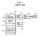
- a previously proposed network system for mobile radio communication which includes a radio connection unit 55 for selecting a line to be connected through a communication network 56, radio base stations 53 and 54 respectively installed in a plurality of unit cells, and a mobile radio terminal (to be referred to as a PS hereinafter) 48 which establishes a radio channel with a radio base station while moving.
- the PS 48 includes a buffer memory (to be referred to as a BM hereinafter) 50 for temporarily storing data in a line switching operation, a data device 51, a data processing apparatus 49, and a communication controller 52.
- the radio base station (1) 53 determines the necessity for line switching during communication between the PS 48 and the radio base station (1) 53, the radio base station (1) 53 sends a line switching notification to the radio connection unit 55, and also sends a communication interruption notification to the data processing apparatus 49.
- the data processing apparatus 49 transmits an acknowledgement signal to the radio connection unit 55 and starts to store, in the BM 50, the communication data which has been directly transmitted.
- the radio connection unit 55 receives the acknowledgement signal from the data processing apparatus 49, the communication between the PS 48 and the radio base station (1) 53 is interrupted. While the data processing apparatus 49 is storing the communication data, line switching processing is performed.
- the radio connection unit 55 sends a switching instruction to the radio base station (1) 53, that has been serving up until now, and the radio base station (2) 54 that is to serve next.
- the radio base station (1) 53 as the currently serving station sends a switching instruction to the communication controller 52.
- the communication controller 52 When these operations are complete, the communication is resumed.
- the data processing apparatus 49 reads out the data stored in the BM 50 and transmits the data to the radio base station (2) 54 through the communication controller 52. When all the data are read out from the BM 50, direct communication without the mediacy of the BM 50 is started again.
- the server unit that transmits/receives data to/from the PS has no BM for storing data. For this reason, if a hit occurs during data transmission from the server unit to the PS, data is lost.
- the radio base station must monitor the reception state of the PS so as to send a line switching instruction thereto. For this reason, line switching processing is complicated, resulting in a decrease in line switching speed.
- a PS is connected to a public radio base station (to be referred to as a public CS hereinafter) or a private radio base station (to be referred to as a private CS hereinafter) to perform data communication with a server unit in a network, and that data losses can be minimised even if slot errors or a reduction in electric field strength occur between a PS and the CS, thereby providing highly reliable data transmission.
- a public radio base station to be referred to as a public CS hereinafter
- a private radio base station to be referred to as a private CS hereinafter
- a network system for mobile radio communication (which is referred to as a network system for mobile radio communication using a public CS hereinafter) comprising a network constituted by a server unit and a client unit, a radio connection unit connected to a communication network, a public CS installed in a cell, and a PS which establishes a radio channel with the public CS while moving, the network system being adapted to perform data communication between the server unit and the PS, wherein each of the server unit and the PS includes a BM and an auxiliary storage unit which hold data, and the PS includes an electric field strength monitoring section for monitoring slot errors or a reduction in an electric field strength, stores data in the BM during data transmission to the server unit when a level based on slot errors or a reduction in electric field strength is not lower than a threshold for line switching, sends a line switching notification to the server unit, sends a line switching request to the public CS, and starts to transmit the data
- a PS in another network system for mobile radio communication using a public CS, to be described below, by way of example in illustration of the invention, includes a section for instructing a server unit to store data in a BM during data reception from the server unit when an electric field strength monitoring section determines that a level based on slot errors or a reduction in electric field strength is not lower than a threshold for line switching, a section for sending a line switching request to the public CS, and a section for notifying the server unit of completion of line switching upon reception of a response indicating completion of line switching from the public CS, and the server unit includes a section for starting to transmit the data stored in a BM.
- a PS includes a section for sending a server unit a notification indicating that preparation for line disconnection is in progress during data reception from the server unit when a level based on slot errors or a reduction in electric field strength is not lower than a threshold for line disconnection, a section for starting a timer, and a section for notifying the server unit of recovery of the electric field strength when the electric field strength is recovered within a disconnection determination time
- the server unit includes a section for storing data in a BM upon reception of the notification indicating that preparation for line disconnection is in progress from the PS, and a section for starting to transmit the data stored in a BM upon reception of a notification indicating that the electric field strength is recovered.
- a further arrangement to be described below by way of example in illustration of the present invention includes a network system for mobile radio communication using a public CS, in which a PS includes a section for storing data in a BM during data transmission to a server unit when an electric field strength monitoring section determines that a level based on slot errors or a reduction in electric field strength is not lower than a threshold for line disconnection, a section for starting a timer, and a section for starting the data stored in a BM when the electric field strength is recovered within a predetermined disconnection determination time.
- the PS when the electric field strength is not recovered within the disconnection determination time, the PS can output a line disconnection request to the public CS and can perform termination processing in preparation for power off of the PS upon completion of line disconnection.
- a still further network system for mobile radio communication to be described below includes a private network constituted by a radio management server, a server unit, and a client unit, a private CS installed in a cell, and a PS which establishes a radio channel with the private CS while moving, the system being adapted to perform data communication between the server unit and the PS, each of the server unit and the PS including a BM and an auxiliary storage unit which hold data, and the PS including an electric field strength monitoring section for monitoring slot errors or a reduction in electric field strength, a section for storing data in the BM during data transmission to the server unit when a level based on slot errors or a reduction in electric field strength is not lower than a threshold for line switching, a section for sending a line switching notification to the server unit, a section for sending a line switching request to the private CS, and a section for starting to transmit the data stored in the BM upon reception of a response indicating completion of line switching from the private CS.
- a PS includes a section for instructing a server unit to store data in a BM during data reception from the server unit when an electric field strength monitoring section determines that a level based on slot errors or a reduction in electric field strength is not lower than a threshold for line switching, a section for sending a line switching request to the private CS, and a section for notifying the server unit of completion of line switching upon reception of a response indicating completion of line switching from the private CS, and the server unit includes a section for changing a private CS destination ID of the data stored in a BM to a private CS destination ID after line switching, and a section for starting to transmit the stored data.
- a PS includes a section for notifying a server unit that preparation for line disconnection is in progress during data reception from the server unit when an electric field strength monitoring section determines that a level based on slot errors or a reduction in electric field strength is not lower than a threshold for line switching, a section for starting a timer, and a section for notifying the server unit of recovery of the electric field strength when the electric field strength is recovered within a disconnection determination time
- the server unit includes a section for storing data in a BM upon reception of a notification indicating that preparation for line disconnection is in progress from the PS, and a section for starting to transmit the data stored in the BM upon reception of a notification indicating that the electric field strength is recovered.
- a PS includes a section for storing data in a BM during data transmission to a server unit when an electric field strength monitoring section determines that a level based on slot errors or a reduction in electric field strength is not lower than a threshold for line disconnection, a section for starting a timer, and a section for starting to transmit the data stored in a BM when the electric field strength is recovered within a predetermined disconnection determination time.
- the PS can output a line disconnection request to the public CS when the electric field strength is not recovered within the disconnection determination time, and can perform termination processing in preparation for power off of the PS upon completion of line disconnection.
- a network system for mobile radio communication including both a mobile radio network system using a public CS and a mobile radio network system using a private CS will also be described below by way of example in illustration of the invention, in which a PS includes a section for switching connection to the public CS or the private CS.
- a network system for mobile radio communication will be described below with reference to Fig. 2. Assume that a slot error or a reduction in electric field strength occurs between a PS and a public CS during a wide-area information service in which, for example, the user transmits/receives data, outside the office, to/from a server unit connected to a network such as an office LAN through a high-speed network such as an ISDN or a public network such as a telephone line.
- a network such as an office LAN through a high-speed network such as an ISDN or a public network such as a telephone line.
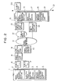
- the first system comprises a network 21 constituted by a server unit 15 and a client unit 20, a line switching unit 9 to which the network 21 is connected through a digital line interface section 14 and a high-speed network 11 or through an analog circuit interface section 13, a public network 12, and the high-speed network 11, a radio connection unit 8 for generating position information on the basis of a PS position registration request from a public CS (1) 6 or a public CS (2) 7, a radio service control station 10 for recording the position information, and a group of unit cells.
- Each unit cell comprises the public CS (1) 6 or the public CS (2) 7 and a PS 1 which establishes a channel with the public CS (1) 6 or the public CS (2) 7 in the unit cell while moving.
- the PS 1 has a means of requesting the public CS (1) 6 to perform line switching and disconnection.
- the PS 1 includes a data transmission/reception section 2 for transmitting/receiving data, an electric field strength monitoring section 3 for monitoring a slot error or a reduction in electric field strength, a BM 4 for temporarily storing data to be communicated, and an auxiliary storage unit 5 for saving data.
- the server unit 15 includes a data processing section 17 for analyzing a request from the PS 1 and processing necessary data, a data transmission/reception section 16 for transmitting/receiving data, a BM 18 for temporarily storing data to be communicated, and an auxiliary storage unit 19.
- the digital line interface section 14 provides the interface between the high-speed network 11 and the server unit 15.
- the analog circuit interface section 13 provides the interface between the public network 12 and the server unit 15.
- the digital line interface section 14 an assembly of a terminal adaptor, a line controller, and an ISDN board is available.
- TDMA Time Division Multiple Access
- TDD Time Division Duplex
- the thresholds for line switching and line disconnection are specified in advance between the PS and the radio base station, and both the level obtained by monitoring a reduction in electric field strength instead of slot errors and the level based on a combination of monitoring operations for slot errors and a reduction in electric field strength can be compared with the above thresholds. Since a method of monitoring slot errors and a reduction in electric field strength is a known technique in the radio communication schemes, and is not a constituent element of the present invention, a description thereof will be omitted.
- the level based on slot errors or a reduction in electric field strength is equal to or higher than the threshold for line switching, and data is to be transmitted to the server unit.
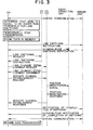
- the procedure required between the PS, the public CS, and the server unit in this case will be described as the first mode of the first system with reference to Fig. 3.
- the data transmission/reception section 2 When the electric field strength monitoring section 3 of the PS 1 determines that the level based on slot errors or a reduction in electric field strength is equal to or higher than the threshold for line switching, the data transmission/reception section 2 temporarily stops the transmission, and stores, in the BM 4, the data which cannot be transmitted. The data transmission/reception section 2 then sends a line switching notification to the server unit 15. Upon reception of an acknowledgement from the server unit 15, the data transmission/reception section 2 requests the public CS (1) 6 to perform line switching.
- the PS 1 Upon reception of the line switching instruction from the public CS (1) 6, the PS 1 sends the public CS (2) 7 a request for establishing a channel for transferring information required to connect the radio base station and the PS (to be referred to as a link line establishment request hereinafter).
- the PS 1 sends the public CS (2) 7 a request for establishing a channel used to transmit/receive data (to be referred to as a service channel establishment request hereinafter).
- the public CS (2) 7 Upon reception of the request, the public CS (2) 7 sends a position registration signal to the radio connection unit 8. The signal is then registered in the radio service control station 10 through the radio connection unit 8 and the line switching unit 9.
- the PS 1 Upon reception of a response signal indicating the completion of line switching from the public CS (2) 7, the PS 1 notifies the server unit 15 of the completion of line switching. Upon reception of an acknowledgement from the server unit 15, the PS 1 starts to transmit the data stored in the BM 4.
- the PS 1 When the electric field strength monitoring section 3 of the PS 1 determines that the level based on slot errors or a reduction electric field strength is equal to or higher than the threshold for line switching, the PS 1 sends a line switching notification to the server unit 15.
- the data transmission/reception section 16 temporarily stops the transmission, stores, in the BM 18, the data which cannot be transmitted, and sends the PS 1 an acknowledgement to the line switching notification.
- the PS 1 Upon reception of the acknowledgement, the PS 1 sends a line switching request to the public CS (1) 6.
- the PS 1 Upon reception of a line switching instruction from the public CS (1) 6, the PS 1 sends a link channel establishment request to the public CS (2) 7. When a link channel is established, the PS 1 sends a service channel establishment request to the public CS (2) 7. Upon reception of the request, the public CS (2) 7 sends a position registration signal to the radio connection unit 8. The signal is then registered in the radio service control station 10 through the radio connection unit 8 and the line switching unit 9. Upon reception of a response indicating the completion of line switching from the public CS (2) 7, the PS 1 notifies the server unit 15 of the completion of line switching. The server unit 15 sends an acknowledgement to the PS 1 and starts to transmit the data stored in the BM 18.
- the PS 1 sends a line disconnection preparation notification to the server unit 15.
- the data transmission/reception section 16 temporarily stops the transmission, stores, in the BM 18, the data which cannot be transmitted, and sends an acknowledgement to the PS 1.
- the PS 1 starts the timer and checks whether the electric field strength is recovered within a predetermined disconnection determination time. If the electric field strength is recovered within the predetermined disconnection determination time, the PS 1 notifies the server unit 15 that line disconnection is not required. The server unit 15 then sends an acknowledgement to the PS 1, and starts to transmit the data stored in the BM 18.
- the data transmission/reception section 2 temporarily stops the transmission, stores, in the BM 4, the data which cannot be transmitted, and sends a line disconnection preparation notification to the server unit 15.
- the PS 1 Upon reception of an acknowledgement from the server unit 15, the PS 1 starts the timer, and checks whether the electric field strength is recovered within a predetermined disconnection determination time. If the electric field strength is recovered within the disconnection determination time, the PS 1 notifies the server unit 15 that line disconnection is not required.
- the PS 1 starts to transmit the data stored in the BM 4.
- the PS 1 sends a line disconnection request to the public CS (1) 6.
- the PS 1 Upon reception of a line disconnection instruction from the public CS (1) 6, the PS 1 disconnects the line, and notifies the public CS (1) 6 that the line is disconnected.
- the PS 1 is then powered off.
- the PS 1 is powered on again, the operation state indicated by the information saved in the auxiliary storage unit 5 is restored.
- the PS 1 retransmits the data saved in the auxiliary storage unit 5.
- Fig. 8 is a block diagram showing the overall arrangement of the second system of the present invention.
- a network system for mobile radio communication will be described below. Assume that a slot error or a reduction in electric field strength occurs between a PS and a private CS during a local information service system or the like in which, for example, data is transmitted/received to/from a server unit connected to a network in facilities such as an amusement park without the mediacy of a line.
- the second system comprises a network A23 constituted by a radio management server A26, a group of unit cells, a server unit A27, and a client unit (1) 29, and a network B31 constituted by a radio management server B32, a group of unit cells, a server unit B33, and a client unit (2) 34.
- Each unit cell is constituted by a private CS (1) 24 and a CS (2) 25, or a CS (3) 36 and a CS (4) 37, and a PS (1) 22 or a PS (2) 38 which establishes a channel with a private CS in the unit cell while moving.
- the PS (1) 22 or the PS (2) 38 has a means of requesting a private CS to perform line switching and disconnection.
- Each PS includes a data transmission/reception section 2 for transmitting/receiving data, an electric field strength monitoring section 3 for monitoring slot errors or a reduction in electric field strength due to interference, a BM 4 for temporarily storing data to be communicated, and an auxiliary storage unit 5 for saving data.
- Each of the server units 27 and 33 includes a data processing section 17 for analyzing a request from a corresponding one of the PS (1) 22 and the PS (2) 38, and processing necessary data, a data transmission/reception section 16 for transmitting/receiving data, a BM 18 for temporarily storing data to be communicated, an auxiliary storage unit 19, and an ID changing section 28.
- the address of the PS is registered in the radio management server in advance, and the radio management server can transmit data to the PS by changing the destination of the data on the basis of the address.
- the level based on slot errors or a reduction in electric field strength is equal to or higher than a threshold for line switching, and data is to be transmitted to the server unit.
- the procedure required between the PS, the private CS, and the server unit in this case will be described below as the first mode of the second system with reference to Fig. 9.
- the data transmission/reception section 2 temporarily stops the transmission, stores, in the BM 4, the data which cannot be transmitted, and sends a line switching notification to the server unit A27.
- the PS (1) 22 Upon reception of an acknowledgement from the server unit A27, the PS (1) 22 sends a line switching request to the private CS (1) 24.
- the PS (1) 22 Upon reception of a line switching instruction from the private CS (1) 24, the PS (1) 22 sends a link channel establishment request to the private CS (2) 25. When a link channel is established, the PS (1) 22 sends a service channel establishment request to the private CS (2) 25.
- the private CS (2) 25 requests the radio management server A26 to change the ID of the PS (1) 22.
- the radio management server A26 changes the ID of the PS (1) 22, holds the ID data, and notifies the server unit A27 that the ID has been changed.
- the PS (1) 22 Upon reception of a response indicating the completion of line switching from the private CS (2) 25, the PS (1) 22 notifies the server unit A27 of the completion of line switching.
- the PS (1) 22 Upon reception of an acknowledgement from the server unit A27, the PS (1) 22 starts to transmit the data stored in the BM 4.
- the PS (1) 22 sends a line switching notification to the server unit A27.
- the data transmission/reception section 16 temporarily stops the transmission, stores, in the BM 18, the data which cannot be transmitted, and sends the PS (1) 22 an acknowledgement to the line switching notification.
- the PS (1) 22 Upon reception of the acknowledgement, the PS (1) 22 sends a line switching request to the private CS (1) 24. Upon reception of a line switching instruction from the private CS (1) 24, the PS (1) 22 sends a link channel establishment request to the private CS (2) 25. When a link channel is established, the PS (1) 22 sends a service channel establishment request to the private CS (2) 25.
- the private CS (2) 25 requests the radio management server A26 to change the ID of the PS (1) 22.
- the radio management server A26 changes the ID of the PS (1) 22, and holds the ID data.
- the radio management server A26 notifies the server unit A27 that the ID is changed.
- the PS (1) 22 Upon reception of a response indicating the completion of line switching from the private CS (2) 25, the PS (1) 22 notifies the server unit A27 of the completion of line switching.
- the server unit A27 sends an acknowledgement to the PS (1) 22.
- the ID changing section 28 then changes the destination of the data stored in the BM 18, and starts to transmit the data.
- the PS (1) 22 sends a line switching preparation notification to the server unit A27.
- the data transmission/reception section 16 temporarily stops the transmission, stores, in the BM 18, the data which cannot be transmitted, and sends an acknowledgement to the PS (1) 22.
- the PS (1) 22 starts a timer, and checks whether the electric field strength is recovered within a predetermined disconnection determination time. If the electric field strength is recovered within the disconnection determination time, the PS (1) 22 notifies the server unit A27 that line disconnection is not required.
- the server unit A27 sends an acknowledgement to the PS (1) 22, and starts to transmit the data stored in the BM 18.
- the data transmission/reception section 2 temporarily stops the transmission, stores, in the BM 4, the data which cannot be transmitted, and sends a line disconnection notification to the server unit A27.
- the PS (1) 22 Upon reception of an acknowledgement from the server unit A27, the PS (1) 22 starts the timer, and checks whether the electric field strength is recovered within a predetermined disconnection determination time. If the electric field strength is recovered within the disconnection determination time, the PS (1) 22 notifies the server unit A27 that line disconnection is not required. Upon reception of an acknowledgement from the server unit A27, the PS (1) 22 starts to transmit the data stored in the BM 4.
- the PS (1) 22 then sends a line disconnection request to the private CS (1) 24.
- the PS (1) 22 disconnects the line, and notifies the private CS (1) 24 that the line is disconnected.
- the PS (1) 22 is then powered off. When the PS (1) 22 is powered on again, the operation state indicated by the information saved in the auxiliary storage unit 5 is restored. If the electric field strength is recovered, the PS (1) 22 retransmits the data saved in the auxiliary storage unit 5.
- Fig. 14 is a block diagram showing the overall arrangement of the third system of the present invention.
- the third system comprises first and second systems.
- the first system includes a line switching unit 9 to which a network 46 constituted by a server unit 15 and a client unit 47 is connected through a digital line interface section 14 and high-speed network 11 or through an analog circuit interface section 13, a public network 12, and the high-speed network 11, a radio connection unit 8 for generating position information on the basis of a position registration request from a public CS 39, a radio service control station 10 for registering the position information, and a group of unit cells each constituted by a PS 1 which establishes a channel with the public CS 39 while moving, and the public CS 39.
- the second system includes a network 40 constituted by a radio management server 42, a server unit 43, and a client unit 44 and a group of unit cells each constituted by the PS 1 which establishes a channel with a private CS 41 while moving, and the private CS 41.
- the PS 1 when the PS 1 is powered on, a channel is established between the PS 1 and the private CS 41 of the second system which is located in the unit cell.
- the data transmission/reception section 2 of the PS 1 detects the start of connection processing with respect to a public CS, thereby connecting a channel between the PS 1 and the public CS 39 of the first system which is located in the unit cell.
- the PS 1 can transmit/receive data to/from the server unit 43 connected to the network inside the same facilities, or can transmit/receive data to/from the server unit 15 connected to a network such as a LAN in other facilities inside the office.
Abstract
A network system for mobile radio communication includes a network constituted by a server unit and a client unit, a radio connection unit connected to a communication network, a public radio base station installed in a cell, and a mobile radio terminal which establishes a radio channel with the public radio base station while moving. The network system performs data communication between the server unit and the mobile radio terminal. Each of the server unit and the mobile radio terminal includes a buffer memory and an auxiliary storage unit which hold data. The mobile radio terminal includes an electric field strength monitoring section for monitoring slot errors or a reduction in electric field strength, a section for storing data in the buffer memory during data transmission to the server unit when the level based on slot errors or a reduction in electric field strength is equal to or higher than a threshold for line switching, a section for sending a line switching notification to the server unit, a section for sending a line switching request to the public radio base station, and a section for starting to transmit the data stored in the buffer memory upon reception of a response indicating completion of line switching from the public radio base station.
Description
- The present invention relates to a network system for mobile radio communication in which a network system for a mobile radio terminal is connected to a communication through a public or private radio base station to perform data communication with a server unit. A particular system to be described below, by way of example, in illustration of the invention minimises data losses even if slot errors or a drop in electric field strength occur between a mobile radio terminal and a public or private radio base station.
- In Fig. 1 of the accompanying drawings, there is shown a previously proposed network system for mobile radio communication which includes a
radio connection unit 55 for selecting a line to be connected through acommunication network 56,radio base stations PS 48 includes a buffer memory (to be referred to as a BM hereinafter) 50 for temporarily storing data in a line switching operation, adata device 51, adata processing apparatus 49, and a communication controller 52. - As a data transmission scheme in such a system, the scheme disclosed in Japanese Unexamined Patent Publication No. 59-212040 is available.
- More specifically, when the radio base station (1) 53 determines the necessity for line switching during communication between the
PS 48 and the radio base station (1) 53, the radio base station (1) 53 sends a line switching notification to theradio connection unit 55, and also sends a communication interruption notification to thedata processing apparatus 49. Upon reception of the notification, thedata processing apparatus 49 transmits an acknowledgement signal to theradio connection unit 55 and starts to store, in theBM 50, the communication data which has been directly transmitted. When theradio connection unit 55 receives the acknowledgement signal from thedata processing apparatus 49, the communication between thePS 48 and the radio base station (1) 53 is interrupted. While thedata processing apparatus 49 is storing the communication data, line switching processing is performed. When the radio base station (2) 54 to serve next is determined, theradio connection unit 55 sends a switching instruction to the radio base station (1) 53, that has been serving up until now, and the radio base station (2) 54 that is to serve next. Upon reception of the switching instructions, the radio base station (1) 53 as the curently serving station sends a switching instruction to the communication controller 52. When these operations are complete, the communication is resumed. When the communication is resumed, thedata processing apparatus 49 reads out the data stored in theBM 50 and transmits the data to the radio base station (2) 54 through the communication controller 52. When all the data are read out from theBM 50, direct communication without the mediacy of theBM 50 is started again. - The following problems are posed in the above previously proposed data transmission scheme.
- First, in data transmission between a server unit, which is assumed to be outside the area covered by a communication network, and a PS, the server unit that transmits/receives data to/from the PS has no BM for storing data. For this reason, if a hit occurs during data transmission from the server unit to the PS, data is lost.
- Second, no consideration is given to a case wherein line disconnection cannot be avoided because of continuous slot errors or a continuous reduction in electric field strength. For this reason, data is lost when the line is disconnected.
- Third, the radio base station must monitor the reception state of the PS so as to send a line switching instruction thereto. For this reason, line switching processing is complicated, resulting in a decrease in line switching speed.
- Features of a a network system for mobile radio communication to be described below, by way of example in illustration of the invention are that a PS is connected to a public radio base station (to be referred to as a public CS hereinafter) or a private radio base station (to be referred to as a private CS hereinafter) to perform data communication with a server unit in a network, and that data losses can be minimised even if slot errors or a reduction in electric field strength occur between a PS and the CS, thereby providing highly reliable data transmission.
- In one arrangement to be described below, by way of example in illustration of the present invention, there is provided a network system for mobile radio communication (which is referred to as a network system for mobile radio communication using a public CS hereinafter) comprising a network constituted by a server unit and a client unit, a radio connection unit connected to a communication network, a public CS installed in a cell, and a PS which establishes a radio channel with the public CS while moving, the network system being adapted to perform data communication between the server unit and the PS, wherein each of the server unit and the PS includes a BM and an auxiliary storage unit which hold data, and the PS includes an electric field strength monitoring section for monitoring slot errors or a reduction in an electric field strength, stores data in the BM during data transmission to the server unit when a level based on slot errors or a reduction in electric field strength is not lower than a threshold for line switching, sends a line switching notification to the server unit, sends a line switching request to the public CS, and starts to transmit the data stored in the BM upon reception of a response indicating completion of line switching from the public CS.
- In another network system for mobile radio communication using a public CS, to be described below, by way of example in illustration of the invention a PS includes a section for instructing a server unit to store data in a BM during data reception from the server unit when an electric field strength monitoring section determines that a level based on slot errors or a reduction in electric field strength is not lower than a threshold for line switching, a section for sending a line switching request to the public CS, and a section for notifying the server unit of completion of line switching upon reception of a response indicating completion of line switching from the public CS, and the server unit includes a section for starting to transmit the data stored in a BM.
- In yet another arrangement to be described below by way of example in illustration of the present invention, there is a network system for mobile radio communication using a public CS, in which a PS includes a section for sending a server unit a notification indicating that preparation for line disconnection is in progress during data reception from the server unit when a level based on slot errors or a reduction in electric field strength is not lower than a threshold for line disconnection, a section for starting a timer, and a section for notifying the server unit of recovery of the electric field strength when the electric field strength is recovered within a disconnection determination time, and the server unit includes a section for storing data in a BM upon reception of the notification indicating that preparation for line disconnection is in progress from the PS, and a section for starting to transmit the data stored in a BM upon reception of a notification indicating that the electric field strength is recovered.
- A further arrangement to be described below by way of example in illustration of the present invention, includes a network system for mobile radio communication using a public CS, in which a PS includes a section for storing data in a BM during data transmission to a server unit when an electric field strength monitoring section determines that a level based on slot errors or a reduction in electric field strength is not lower than a threshold for line disconnection, a section for starting a timer, and a section for starting the data stored in a BM when the electric field strength is recovered within a predetermined disconnection determination time.
- In yet a further arrangement to be described below, by way of example in illustration of the present invention, in a network system for mobile radio communication, when the electric field strength is not recovered within the disconnection determination time, the PS can output a line disconnection request to the public CS and can perform termination processing in preparation for power off of the PS upon completion of line disconnection.
- A still further network system for mobile radio communication to be described below, by way of example in illustration of the invention includes a private network constituted by a radio management server, a server unit, and a client unit, a private CS installed in a cell, and a PS which establishes a radio channel with the private CS while moving, the system being adapted to perform data communication between the server unit and the PS, each of the server unit and the PS including a BM and an auxiliary storage unit which hold data, and the PS including an electric field strength monitoring section for monitoring slot errors or a reduction in electric field strength, a section for storing data in the BM during data transmission to the server unit when a level based on slot errors or a reduction in electric field strength is not lower than a threshold for line switching, a section for sending a line switching notification to the server unit, a section for sending a line switching request to the private CS, and a section for starting to transmit the data stored in the BM upon reception of a response indicating completion of line switching from the private CS.
- There will also be described below, by way of example in illustration of the present invention, a network system for mobile radio communication using a private CS, in which a PS includes a section for instructing a server unit to store data in a BM during data reception from the server unit when an electric field strength monitoring section determines that a level based on slot errors or a reduction in electric field strength is not lower than a threshold for line switching, a section for sending a line switching request to the private CS, and a section for notifying the server unit of completion of line switching upon reception of a response indicating completion of line switching from the private CS, and the server unit includes a section for changing a private CS destination ID of the data stored in a BM to a private CS destination ID after line switching, and a section for starting to transmit the stored data.
- A network system for mobile radio communication using a private CS will also be described below, by way of example, in illustration of the invention, in which a PS includes a section for notifying a server unit that preparation for line disconnection is in progress during data reception from the server unit when an electric field strength monitoring section determines that a level based on slot errors or a reduction in electric field strength is not lower than a threshold for line switching, a section for starting a timer, and a section for notifying the server unit of recovery of the electric field strength when the electric field strength is recovered within a disconnection determination time, and the server unit includes a section for storing data in a BM upon reception of a notification indicating that preparation for line disconnection is in progress from the PS, and a section for starting to transmit the data stored in the BM upon reception of a notification indicating that the electric field strength is recovered.
- A further network system for mobile radio communication using a private CS will also be described below, in illustration of the invention, in which a PS includes a section for storing data in a BM during data transmission to a server unit when an electric field strength monitoring section determines that a level based on slot errors or a reduction in electric field strength is not lower than a threshold for line disconnection, a section for starting a timer, and a section for starting to transmit the data stored in a BM when the electric field strength is recovered within a predetermined disconnection determination time.
- In this network system for mobile radio communication the PS can output a line disconnection request to the public CS when the electric field strength is not recovered within the disconnection determination time, and can perform termination processing in preparation for power off of the PS upon completion of line disconnection.
- A network system for mobile radio communication including both a mobile radio network system using a public CS and a mobile radio network system using a private CS will also be described below by way of example in illustration of the invention, in which a PS includes a section for switching connection to the public CS or the private CS.
- Furthermore, in a system in which a PS is connected to a radio base station to perform data communication with a server unit in a network to be described below, by way of example in illustration of the invention, even if slot errors or a reduction in electric field strength occurs between the PS and the radio base station, data losses can be minimised, and highly reliable data transmission can be provided.
- The following description and drawings disclose, by means of examples, the invention which is characterised in the appended claims, whose terms determine the extent of the protection conferred hereby.
- In the drawings:-
- Fig. 2 is a block diagram showing the overall arrangement of a first system,
- Fig. 3 is a flow chart showing a first mode procedure for the first system,
- Fig. 4 is a flow chart showing a second mode procedure for the first system,
- Fig. 5 is a flow chart showing a third mode procedure for the first system,
- Fig. 6 is a flow chart showing a fourth mode procedure for the first system,
- Fig. 7 is a flow chart showing a fifth mode procedure for the first system,
- Fig. 8 is a block diagram showing the overall arrangement of a second system,
- Fig. 9 is a flow chart showing a first mode procedure for the second system,
- Fig. 10 is a flow chart showing a second mode procedure for second mode of the second system,
- Fig. 11 is a flow chart showing a third mode procedure for the second system,
- Fig. 12 is a flow chart showing a fourth mode procedure for the second system,
- Fig. 13 is a flow chart showing a fifth mode procedure for the second system, and
- Fig. 14 is a block diagram showing the overall arrangement of a third system.
- A network system for mobile radio communication will be described below with reference to Fig. 2. Assume that a slot error or a reduction in electric field strength occurs between a PS and a public CS during a wide-area information service in which, for example, the user transmits/receives data, outside the office, to/from a server unit connected to a network such as an office LAN through a high-speed network such as an ISDN or a public network such as a telephone line. The first system comprises a
network 21 constituted by aserver unit 15 and aclient unit 20, aline switching unit 9 to which thenetwork 21 is connected through a digitalline interface section 14 and a high-speed network 11 or through an analogcircuit interface section 13, apublic network 12, and the high-speed network 11, aradio connection unit 8 for generating position information on the basis of a PS position registration request from a public CS (1) 6 or a public CS (2) 7, a radioservice control station 10 for recording the position information, and a group of unit cells. Each unit cell comprises the public CS (1) 6 or the public CS (2) 7 and aPS 1 which establishes a channel with the public CS (1) 6 or the public CS (2) 7 in the unit cell while moving. - In the above system, the
PS 1 has a means of requesting the public CS (1) 6 to perform line switching and disconnection. ThePS 1 includes a data transmission/reception section 2 for transmitting/receiving data, an electric fieldstrength monitoring section 3 for monitoring a slot error or a reduction in electric field strength, aBM 4 for temporarily storing data to be communicated, and anauxiliary storage unit 5 for saving data. Theserver unit 15 includes adata processing section 17 for analyzing a request from thePS 1 and processing necessary data, a data transmission/reception section 16 for transmitting/receiving data, aBM 18 for temporarily storing data to be communicated, and anauxiliary storage unit 19. The digitalline interface section 14 provides the interface between the high-speed network 11 and theserver unit 15. The analogcircuit interface section 13 provides the interface between thepublic network 12 and theserver unit 15. As the digitalline interface section 14, an assembly of a terminal adaptor, a line controller, and an ISDN board is available. As the analogcircuit interface section 13, a modem is available. Note that the above interface sections can be replaced with other interface devices in accordance with an increase in the communication speed of a line. - Assume that in a 4-channel multiplex multi-carrier TDMA (Time Division Multiple Access)/TDD (Time Division Duplex), a digital signal on one radio carrier is divided into frames at 5-ms intervals, and each frame is further divided into eight slots, and that a slot error indicates a state wherein data transmitted from a home station in a given slot cannot be received by a distant station.
- Assume also that the thresholds for line switching and line disconnection are specified in advance between the PS and the radio base station, and both the level obtained by monitoring a reduction in electric field strength instead of slot errors and the level based on a combination of monitoring operations for slot errors and a reduction in electric field strength can be compared with the above thresholds. Since a method of monitoring slot errors and a reduction in electric field strength is a known technique in the radio communication schemes, and is not a constituent element of the present invention, a description thereof will be omitted.
- Assume that in the above arrangement, the level based on slot errors or a reduction in electric field strength is equal to or higher than the threshold for line switching, and data is to be transmitted to the server unit. The procedure required between the PS, the public CS, and the server unit in this case will be described as the first mode of the first system with reference to Fig. 3.
- When the electric field
strength monitoring section 3 of thePS 1 determines that the level based on slot errors or a reduction in electric field strength is equal to or higher than the threshold for line switching, the data transmission/reception section 2 temporarily stops the transmission, and stores, in theBM 4, the data which cannot be transmitted. The data transmission/reception section 2 then sends a line switching notification to theserver unit 15. Upon reception of an acknowledgement from theserver unit 15, the data transmission/reception section 2 requests the public CS (1) 6 to perform line switching. - Upon reception of the line switching instruction from the public CS (1) 6, the
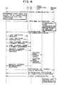
PS 1 sends the public CS (2) 7 a request for establishing a channel for transferring information required to connect the radio base station and the PS (to be referred to as a link line establishment request hereinafter). When the link line is established, thePS 1 sends the public CS (2) 7 a request for establishing a channel used to transmit/receive data (to be referred to as a service channel establishment request hereinafter). Upon reception of the request, the public CS (2) 7 sends a position registration signal to theradio connection unit 8. The signal is then registered in the radioservice control station 10 through theradio connection unit 8 and theline switching unit 9. Upon reception of a response signal indicating the completion of line switching from the public CS (2) 7, thePS 1 notifies theserver unit 15 of the completion of line switching. Upon reception of an acknowledgement from theserver unit 15, thePS 1 starts to transmit the data stored in theBM 4. - Assume that the level based on slot errors or a reduction in electric field strength is equal to or higher than the threshold for line switching, and data is to be received from the server unit. The procedure required between the PS, the public CS, and the server unit in this case will be described as the second mode of the first system with reference to Fig. 4.
- When the electric field
strength monitoring section 3 of thePS 1 determines that the level based on slot errors or a reduction electric field strength is equal to or higher than the threshold for line switching, thePS 1 sends a line switching notification to theserver unit 15. In theserver unit 15, the data transmission/reception section 16 temporarily stops the transmission, stores, in theBM 18, the data which cannot be transmitted, and sends thePS 1 an acknowledgement to the line switching notification. Upon reception of the acknowledgement, thePS 1 sends a line switching request to the public CS (1) 6. - Upon reception of a line switching instruction from the public CS (1) 6, the
PS 1 sends a link channel establishment request to the public CS (2) 7. When a link channel is established, thePS 1 sends a service channel establishment request to the public CS (2) 7. Upon reception of the request, the public CS (2) 7 sends a position registration signal to theradio connection unit 8. The signal is then registered in the radioservice control station 10 through theradio connection unit 8 and theline switching unit 9. Upon reception of a response indicating the completion of line switching from the public CS (2) 7, thePS 1 notifies theserver unit 15 of the completion of line switching. Theserver unit 15 sends an acknowledgement to thePS 1 and starts to transmit the data stored in theBM 18. - Assume that the level based on slot errors or a reduction in electric field strength is equal to or higher than the threshold for line switching, and data is to be received from the server unit. The procedure required between the PS, the public CS, and the server unit in this case will be described as the third mode of the first system with reference to Fig. 5.
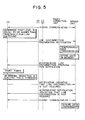
- When the electric field
strength monitoring section 3 determines that the level based on slot errors or a reduction in electric field strength is equal to or higher than the threshold for line disconnection, thePS 1 sends a line disconnection preparation notification to theserver unit 15. In theserver unit 15, the data transmission/reception section 16 temporarily stops the transmission, stores, in theBM 18, the data which cannot be transmitted, and sends an acknowledgement to thePS 1. Upon reception of the acknowledgement, thePS 1 starts the timer and checks whether the electric field strength is recovered within a predetermined disconnection determination time. If the electric field strength is recovered within the predetermined disconnection determination time, thePS 1 notifies theserver unit 15 that line disconnection is not required. Theserver unit 15 then sends an acknowledgement to thePS 1, and starts to transmit the data stored in theBM 18. - Assume that the level based on slot errors or a reduction in electric field strength is equal to or higher than the threshold for line switching, and data is to be transmitted to the server unit. The procedure required between the PS, the public CS, and the server unit in this case will be described as the fourth mode of the first system with reference to Fig. 6.
- When the electric field
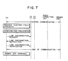
strength monitoring section 3 of thePS 1 determines that the level based on slot errors or a reduction in electric field strength is equal to or higher than the threshold for line disconnection, the data transmission/reception section 2 temporarily stops the transmission, stores, in theBM 4, the data which cannot be transmitted, and sends a line disconnection preparation notification to theserver unit 15. Upon reception of an acknowledgement from theserver unit 15, thePS 1 starts the timer, and checks whether the electric field strength is recovered within a predetermined disconnection determination time. If the electric field strength is recovered within the disconnection determination time, thePS 1 notifies theserver unit 15 that line disconnection is not required. Upon reception of an acknowledgement from theserver unit 15, thePS 1 starts to transmit the data stored in theBM 4. - The procedure required between the PS, the public CS, and the server unit when the electric field strength is not recovered within the predetermined determination time in the fourth mode will be described below as the fifth mode of the first system with reference to Fig. 7.
- If the electric field strength is not recovered within the disconnection determination time, the data stored in the
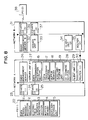
BM 4 and information indicating the current operation state are saved in theauxiliary storage unit 5. ThePS 1 sends a line disconnection request to the public CS (1) 6. Upon reception of a line disconnection instruction from the public CS (1) 6, thePS 1 disconnects the line, and notifies the public CS (1) 6 that the line is disconnected. ThePS 1 is then powered off. When thePS 1 is powered on again, the operation state indicated by the information saved in theauxiliary storage unit 5 is restored. When the electric field strength is recovered, thePS 1 retransmits the data saved in theauxiliary storage unit 5. - Fig. 8 is a block diagram showing the overall arrangement of the second system of the present invention. A network system for mobile radio communication will be described below. Assume that a slot error or a reduction in electric field strength occurs between a PS and a private CS during a local information service system or the like in which, for example, data is transmitted/received to/from a server unit connected to a network in facilities such as an amusement park without the mediacy of a line.
- The second system comprises a network A23 constituted by a radio management server A26, a group of unit cells, a server unit A27, and a client unit (1) 29, and a network B31 constituted by a radio management server B32, a group of unit cells, a server unit B33, and a client unit (2) 34. Each unit cell is constituted by a private CS (1) 24 and a CS (2) 25, or a CS (3) 36 and a CS (4) 37, and a PS (1) 22 or a PS (2) 38 which establishes a channel with a private CS in the unit cell while moving.
- The PS (1) 22 or the PS (2) 38 has a means of requesting a private CS to perform line switching and disconnection. Each PS includes a data transmission/
reception section 2 for transmitting/receiving data, an electric fieldstrength monitoring section 3 for monitoring slot errors or a reduction in electric field strength due to interference, aBM 4 for temporarily storing data to be communicated, and anauxiliary storage unit 5 for saving data. Each of theserver units data processing section 17 for analyzing a request from a corresponding one of the PS (1) 22 and the PS (2) 38, and processing necessary data, a data transmission/reception section 16 for transmitting/receiving data, aBM 18 for temporarily storing data to be communicated, anauxiliary storage unit 19, and anID changing section 28. - Assume that in the above system, the address of the PS is registered in the radio management server in advance, and the radio management server can transmit data to the PS by changing the destination of the data on the basis of the address.
- Assume that in the above arrangement, the level based on slot errors or a reduction in electric field strength is equal to or higher than a threshold for line switching, and data is to be transmitted to the server unit. The procedure required between the PS, the private CS, and the server unit in this case will be described below as the first mode of the second system with reference to Fig. 9.
- When the electric field
strength monitoring section 3 of the PS (1) 22 determines that the level based on slot errors or a reduction in electric field strength is equal to or higher than the threshold for line switching, the data transmission/reception section 2 temporarily stops the transmission, stores, in theBM 4, the data which cannot be transmitted, and sends a line switching notification to the server unit A27. Upon reception of an acknowledgement from the server unit A27, the PS (1) 22 sends a line switching request to the private CS (1) 24. - Upon reception of a line switching instruction from the private CS (1) 24, the PS (1) 22 sends a link channel establishment request to the private CS (2) 25. When a link channel is established, the PS (1) 22 sends a service channel establishment request to the private CS (2) 25. Upon reception of the request, the private CS (2) 25 requests the radio management server A26 to change the ID of the PS (1) 22. Upon reception of the request, the radio management server A26 changes the ID of the PS (1) 22, holds the ID data, and notifies the server unit A27 that the ID has been changed. Upon reception of a response indicating the completion of line switching from the private CS (2) 25, the PS (1) 22 notifies the server unit A27 of the completion of line switching. Upon reception of an acknowledgement from the server unit A27, the PS (1) 22 starts to transmit the data stored in the
BM 4. - Assume that the level based on slot errors or a reduction in electric field strength is equal to or higher than a threshold for line switching, and data is to be received from the server unit. The procedure required between the PS, the private CS, and the server unit in this case will be described below as the second mode of the second system with reference to Fig. 10.
- When the electric field
strength monitoring section 3 determines that the level based on slot errors or a reduction in electric field strength is equal to or higher than the threshold for line switching, the PS (1) 22 sends a line switching notification to the server unit A27. In the server unit A27, the data transmission/reception section 16 temporarily stops the transmission, stores, in theBM 18, the data which cannot be transmitted, and sends the PS (1) 22 an acknowledgement to the line switching notification. - Upon reception of the acknowledgement, the PS (1) 22 sends a line switching request to the private CS (1) 24. Upon reception of a line switching instruction from the private CS (1) 24, the PS (1) 22 sends a link channel establishment request to the private CS (2) 25. When a link channel is established, the PS (1) 22 sends a service channel establishment request to the private CS (2) 25.
- Upon reception of the request, the private CS (2) 25 requests the radio management server A26 to change the ID of the PS (1) 22. Upon reception of the request, the radio management server A26 changes the ID of the PS (1) 22, and holds the ID data. At the same time, the radio management server A26 notifies the server unit A27 that the ID is changed. Upon reception of a response indicating the completion of line switching from the private CS (2) 25, the PS (1) 22 notifies the server unit A27 of the completion of line switching. The server unit A27 sends an acknowledgement to the PS (1) 22. The
ID changing section 28 then changes the destination of the data stored in theBM 18, and starts to transmit the data. - Assume that the level based on slot errors or a reduction in electric field strength is equal to or higher than a threshold for line disconnection, and data is to be received from the server unit. The procedure required between the PS, the private CS, and the server unit in this case will be described below as the third mode of the second system with reference to Fig. 11.
- When the electric field
strength monitoring section 3 of the PS (1) 22 determines that the level based on slot errors or a reduction in electric field strength is equal to or higher than the threshold for line switching, the PS (1) 22 sends a line switching preparation notification to the server unit A27. In the server unit A27, the data transmission/reception section 16 temporarily stops the transmission, stores, in theBM 18, the data which cannot be transmitted, and sends an acknowledgement to the PS (1) 22. Upon reception of the acknowledgement, the PS (1) 22 starts a timer, and checks whether the electric field strength is recovered within a predetermined disconnection determination time. If the electric field strength is recovered within the disconnection determination time, the PS (1) 22 notifies the server unit A27 that line disconnection is not required. The server unit A27 sends an acknowledgement to the PS (1) 22, and starts to transmit the data stored in theBM 18. - Assume that the level based on slot errors or a reduction in electric field strength is equal to or higher than a threshold for line disconnection, and data is to be transmitted to the server unit. The procedure required between the PS, the private CS, and the server unit in this case will be described below as the fourth mode of the second system with reference to Fig. 12.
- When the electric field
strength monitoring section 3 of the PS (1) 22 determines that the level based on slot errors or a reduction in electric field strength is equal to or higher than the threshold for line connection, the data transmission/reception section 2 temporarily stops the transmission, stores, in theBM 4, the data which cannot be transmitted, and sends a line disconnection notification to the server unit A27. Upon reception of an acknowledgement from the server unit A27, the PS (1) 22 starts the timer, and checks whether the electric field strength is recovered within a predetermined disconnection determination time. If the electric field strength is recovered within the disconnection determination time, the PS (1) 22 notifies the server unit A27 that line disconnection is not required. Upon reception of an acknowledgement from the server unit A27, the PS (1) 22 starts to transmit the data stored in theBM 4. - The procedure required between the PS, the private CS, and the server unit when the electric field strength is not recovered within the disconnection determination time in the fourth mode will be described below as the fifth mode of the second system with reference to Fig. 13.
- If the electric field strength is not recovered within the disconnection determination time, the data stored in the
BM 4 and information indicating the current operation state are saved in theauxiliary storage unit 5. The PS (1) 22 then sends a line disconnection request to the private CS (1) 24. Upon reception of a line disconnection instruction from the private CS (1) 24, the PS (1) 22 disconnects the line, and notifies the private CS (1) 24 that the line is disconnected. The PS (1) 22 is then powered off. When the PS (1) 22 is powered on again, the operation state indicated by the information saved in theauxiliary storage unit 5 is restored. If the electric field strength is recovered, the PS (1) 22 retransmits the data saved in theauxiliary storage unit 5. - Fig. 14 is a block diagram showing the overall arrangement of the third system of the present invention.
- The third system comprises first and second systems. The first system includes a
line switching unit 9 to which anetwork 46 constituted by aserver unit 15 and aclient unit 47 is connected through a digitalline interface section 14 and high-speed network 11 or through an analogcircuit interface section 13, apublic network 12, and the high-speed network 11, aradio connection unit 8 for generating position information on the basis of a position registration request from apublic CS 39, a radioservice control station 10 for registering the position information, and a group of unit cells each constituted by aPS 1 which establishes a channel with thepublic CS 39 while moving, and thepublic CS 39. The second system includes anetwork 40 constituted by aradio management server 42, aserver unit 43, and aclient unit 44 and a group of unit cells each constituted by thePS 1 which establishes a channel with aprivate CS 41 while moving, and theprivate CS 41. - In this system, for example, when the
PS 1 is powered on, a channel is established between thePS 1 and theprivate CS 41 of the second system which is located in the unit cell. When the user operates a switch like a public station button which makes the user notice the use of a communication network, the data transmission/reception section 2 of thePS 1 detects the start of connection processing with respect to a public CS, thereby connecting a channel between thePS 1 and thepublic CS 39 of the first system which is located in the unit cell. When theprivate CS 41 of the second system or thepublic CS 39 of the first system is selected in this manner, thePS 1 can transmit/receive data to/from theserver unit 43 connected to the network inside the same facilities, or can transmit/receive data to/from theserver unit 15 connected to a network such as a LAN in other facilities inside the office. - It will be understood that although embodiments illustrative of the invention have been described, by way of example, with reference to the accompanying drawings, variations and modifications thereof, as well as other embodiments, may be made within the scope of the protection sought by the appended claims.
Claims (11)
- A network system for mobile radio communication including a network constituted by a server unit and a client unit, a radio connection unit connected to a communication network, a public radio base station installed in a cell, and a mobile radio terminal which establishes a radio channel with said public radio base station while moving, said system being adapted to perform data communication between said server unit and said mobile radio terminal,
each of said server unit and said mobile radio terminal including a buffer memory and an auxiliary storage unit which hold data, and said mobile radio terminal including an electric field strength monitoring section for monitoring slot errors or a reduction in electric field strength, means for storing data in said buffer memory during data transmission to said server unit when a level based on slot errors or a reduction in electric field strength is not lower than a threshold for line switching, means for sending a line switching notification to said server unit, means for sending a line switching request to said public radio base station, and means for starting to transmit the data stored in said buffer memory upon reception of a response indicating completion of line switching from said public radio base station. - A network system for mobile radio communication including a network constituted by a server unit and a client unit, a radio connection unit connected to a communication network, a public radio base station installed in a cell, and a mobile radio terminal which establishes a radio channel with said public radio base station while moving, said system being adapted to perform data communication between said server unit and said mobile radio terminal,
said mobile radio terminal including means for instructing said server unit to store data in a buffer memory during data reception from said server unit when an electric field strength monitoring section determines that a level based on slot errors or a reduction in electric field strength is not lower than a threshold for line switching, means for sending a line switching request to said public radio base station, and means for notifying said server unit of completion of line switching upon reception of a response indicating completion of line switching from said public radio base station, and said server unit including means for starting to transmit the data stored in said buffer memory. - A network system for mobile radio communication including a network constituted by a server unit and a client unit, a radio connection unit connected to a communication network, a public radio base station installed in a cell, and a mobile radio terminal which establishes a radio channel with said public radio base station while moving, said system being adapted to perform data communication between said server unit and said mobile radio terminal,
said mobile radio terminal including means for sending said server unit a notification indicating that line disconnection is being prepared during data reception from said server unit when a level based on slot errors or a reduction in electric field strength is not lower than a threshold for line disconnection, means for starting a timer, and means for notifying said server unit of recovery of the electric field strength when the electric field strength is recovered within a disconnection determination time, and said server unit including means for storing data in a buffer memory upon reception of the notification indicating that preparation for line disconnection is in progress from said mobile radio terminal, and means for starting to transmit the data stored in said buffer memory upon reception of a notification indicating that the electric field strength is recovered. - A network system for mobile radio communication including a network constituted by a server unit and a client unit, a radio connection unit connected to a communication network, a public radio base station installed in a cell, and a mobile radio terminal which establishes a radio channel with said public radio base station while moving, said system being adapted to perform data communication between said server unit and said mobile radio terminal,
said mobile radio terminal including means for storing data in a buffer memory during data transmission to said server unit when an electric field strength monitoring section determines that a level based on slot errors or a reduction in electric field strength is not lower than a threshold for line disconnection, means for starting a timer, and means for starting the data stored in said buffer memory when the electric field strength is recovered within a predetermined disconnection determination time. - A network system as claimed in claim 4, wherein said mobile radio terminal includes means for outputting a line disconnection request to said public radio base station when the electric field strength is not recovered within the disconnection determination time, and means for performing termination processing in preparation for power off of said mobile radio terminal upon completion of line disconnection.
- A network system for mobile radio communication including a private network constituted by a radio management server, a server unit, and a client unit, a private radio base station installed in a cell, and a mobile radio terminal which establishes a radio channel with said private radio base station while moving, said system being adapted to perform data communication between said server unit and said mobile radio terminal,
each of said server unit and said mobile radio terminal including a buffer memory and an auxiliary storage unit which hold data, and said mobile radio terminal including an electric field strength monitoring section for monitoring slot errors or a reduction in electric field strength, means for storing data in said buffer memory during data transmission to said server unit when a level based on slot errors or a reduction in electric field strength is not lower than a threshold for line switching, means for sending a line switching notification to said server unit, means for sending a line switching request to said private radio base station, and means for starting to transmit the data stored in said buffer memory upon reception of a response indicating completion of line switching from said private radio base station. - A network system for mobile radio communication including a private network constituted by a radio management server, a server unit, and a client unit, a private radio base station installed in a cell, and a mobile radio terminal which establishes a radio channel with said private radio base station while moving, said system being adapted to perform data communication between said server unit and said mobile radio terminal,
said mobile radio terminal including means for instructing said server unit to store data in a buffer memory during data reception from said server unit when an electric field strength monitoring section determines that a level based on slot errors or a reduction in electric field strength is not lower than a threshold for line switching, means for sending a line switching request to said private radio base station, and means for notifying said server unit of completion of line switching upon reception of a response indicating completion of line switching from said private radio base station, and said server unit including means for changing a private radio base station destination ID of the data stored in said buffer memory to a private radio base station destination ID after line switching, and means for starting to transmit the stored data. - A network system for mobile radio communication including a private network constituted by a radio management server, a server unit, and a client unit, a private radio base station installed in a cell, and a mobile radio terminal which establishes a radio channel with said private radio base station while moving, said system being adapted to perform data communication between said server unit and said mobile radio terminal,
said mobile radio terminal including means for notifying said server unit that preparation for line disconnection is in progress during data reception from said server unit when an electric field strength monitoring section determines that a level based on slot errors or a reduction in electric field strength is not lower than a threshold for line switching, means for starting a timer, and means for notifying said server unit of recovery of the electric field strength when the electric field strength is recovered within a disconnection determination time, and said server unit including means for storing data in a buffer memory upon reception of a notification indicating that line disconnection is being prepared from said mobile radio terminal, and means for starting to transmit the data stored in said buffer memory upon reception of a notification indicating that the electric field strength is recovered. - A network system for mobile radio communication including a private network constituted by a radio management server, a server unit, and a client unit, a private radio base station installed in a cell, and a mobile radio terminal which establishes a radio channel with said private radio base station while moving, said system being adapted to perform data communication between said server unit and said mobile radio terminal,
said mobile radio terminal including means for storing data in a buffer memory during data transmission to said server unit when an electric field strength monitoring section determines that a level based on slot errors or a reduction in electric field strength is not lower than a threshold for line disconnection, means for starting a timer, and means for starting to transmit the data stored in said buffer memory when the electric field strength is recovered within a predetermined disconnection determination time. - A network system as claimed in claim 9, wherein said mobile radio terminal includes means for outputting a line disconnection request to said public radio base station when the electric field strength is not recovered within the disconnection determination time, and means for performing termination processing in preparation for power off of said mobile radio terminal upon completion of line disconnection.
- A network system for mobile radio communication including a first system including a network constituted by a server unit and a client unit, a radio connection unit connected to said network, a public radio base station installed in a cell, and a mobile radio terminal which establishes a radio channel with said public radio base station while moving, and a second system including a private network constituted by a radio management server, a server unit, and a client unit, a private radio base station installed in a cell, and a mobile radio terminal which establishes a radio channel to said private radio base station while moving,
said mobile radio terminal including means for switching connection to said public radio base station of said first system and said private radio base station of said second system.
Applications Claiming Priority (3)
| Application Number | Priority Date | Filing Date | Title |
|---|---|---|---|
| JP96696/96 | 1996-04-18 | ||
| JP8096696A JP2859204B2 (en) | 1996-04-18 | 1996-04-18 | Mobile wireless network system |
| JP9669696 | 1996-04-18 |
Publications (2)
| Publication Number | Publication Date |
|---|---|
| EP0802691A2 true EP0802691A2 (en) | 1997-10-22 |
| EP0802691A3 EP0802691A3 (en) | 2003-11-12 |
Family
ID=14171941
Family Applications (1)
| Application Number | Title | Priority Date | Filing Date |
|---|---|---|---|
| EP97302635A Withdrawn EP0802691A3 (en) | 1996-04-18 | 1997-04-17 | Network system for mobile radio communication |
Country Status (5)
| Country | Link |
|---|---|
| US (1) | US6173184B1 (en) |
| EP (1) | EP0802691A3 (en) |
| JP (1) | JP2859204B2 (en) |
| AU (1) | AU731118B2 (en) |
| CA (1) | CA2202565C (en) |
Cited By (8)
| Publication number | Priority date | Publication date | Assignee | Title |
|---|---|---|---|---|
| EP0920218A2 (en) * | 1997-11-25 | 1999-06-02 | Mitsubishi Denki Kabushiki Kaisha | Data switching apparatus for switching received data without changing coding unit |
| EP0946068A2 (en) * | 1998-03-26 | 1999-09-29 | Nec Corporation | Radio data communication method and system |
| WO2000018153A1 (en) * | 1998-09-21 | 2000-03-30 | Mannesmann Ag | Allocation of a channel for data calls with a different useful signal/disturb signal ratio than for channels used for voice calls in mobile radio networks |
| EP1283649A1 (en) * | 2001-08-08 | 2003-02-12 | Siemens Aktiengesellschaft | Method and apparatus for effective handover in a data transmission system for downlink data transmission |
| WO2003015441A1 (en) * | 2001-08-08 | 2003-02-20 | Siemens Aktiengesellschaft | Method and system for allowing an effective handover in a data transmission system in down-link data transmission |
| EP1848227A1 (en) * | 2006-04-18 | 2007-10-24 | Samsung Electronics Co., Ltd. | Method and apparatus for controlling transmission of message during handover in mobile communication terminal |
| EP2276179A1 (en) * | 2002-04-30 | 2011-01-19 | Panasonic Corporation | Wireless communication drive |
| CN102123360A (en) * | 2010-01-11 | 2011-07-13 | 联发科技股份有限公司 | Wireless messaging method and mobile station |
Families Citing this family (8)
| Publication number | Priority date | Publication date | Assignee | Title |
|---|---|---|---|---|
| JP3107041B2 (en) * | 1998-04-28 | 2000-11-06 | 日本電気株式会社 | Wireless data communication method and apparatus |
| JP3620010B2 (en) | 1998-05-22 | 2005-02-16 | 富士通株式会社 | Apparatus and program recording medium used in wireless communication system |
| US7310529B1 (en) * | 2000-01-24 | 2007-12-18 | Nortel Networks Limited | Packet data traffic control for cellular wireless networks |
| JP2001285508A (en) * | 2000-03-30 | 2001-10-12 | Sogo Keibi Hosho Co Ltd | Security communication system |
| CN1450818B (en) | 2002-03-13 | 2010-04-28 | 株式会社Ntt都科摩 | Mobile node, mobile communication system and communication control method |
| KR20100118146A (en) * | 2008-03-27 | 2010-11-04 | 쿄세라 코포레이션 | Wireless communication device and communication device |
| US8254905B2 (en) * | 2008-07-07 | 2012-08-28 | Cisco Technology, Inc. | Service monitoring and disconnection notification in a wireless gateway device |
| JP5441113B2 (en) * | 2009-11-06 | 2014-03-12 | シャープ株式会社 | Thin client system |
Citations (7)
| Publication number | Priority date | Publication date | Assignee | Title |
|---|---|---|---|---|
| EP0283683A2 (en) * | 1987-03-20 | 1988-09-28 | Hitachi, Ltd. | Portable wireless communication systems and method |
| EP0332818A2 (en) * | 1988-03-18 | 1989-09-20 | Motorola, Inc. | Cellular telephone system with shared radio data channels |
| US4912756A (en) * | 1989-04-07 | 1990-03-27 | Unilink Corporation | Method and apparatus for error-free digital data transmission during cellular telephone handoff, etc. |
| EP0483547A1 (en) * | 1990-10-29 | 1992-05-06 | International Business Machines Corporation | Network address management for a wired network supporting wireless communication to a plurality of mobile users |
| EP0594336A1 (en) * | 1992-10-23 | 1994-04-27 | Matsushita Electric Industrial Co., Ltd. | Data message communication in digital cellular radio telephone system |
| EP0643543A2 (en) * | 1993-09-10 | 1995-03-15 | Alcatel SEL Aktiengesellschaft | Proximity telephone system |
| GB2293945A (en) * | 1994-10-07 | 1996-04-10 | Motorola Inc | Battery saving in a radiotelephone |
Family Cites Families (10)
| Publication number | Priority date | Publication date | Assignee | Title |
|---|---|---|---|---|
| JPH0683134B2 (en) | 1983-05-18 | 1994-10-19 | 株式会社日立製作所 | Mobile wireless communication method |
| US5367558A (en) * | 1988-09-23 | 1994-11-22 | Motorola, Inc. | Cellular cordless telephone |
| PL174337B1 (en) * | 1993-07-02 | 1998-07-31 | Motorola Inc | Method of transferring a radiotelephone call from a given range area into another one |
| US5446736A (en) * | 1993-10-07 | 1995-08-29 | Ast Research, Inc. | Method and apparatus for connecting a node to a wireless network using a standard protocol |
| US5794141A (en) * | 1994-02-24 | 1998-08-11 | Gte Mobile Comm Servinc | Multi-mode communication network with handset-assisted cordless base station activation |
| AU696486B2 (en) * | 1994-12-30 | 1998-09-10 | Telefonaktiebolaget Lm Ericsson (Publ) | System and method relating to cellular communications |
| US5850517A (en) * | 1995-08-31 | 1998-12-15 | Oracle Corporation | Communication link for client-server having agent which sends plurality of requests independent of client and receives information from the server independent of the server |
| US5809415A (en) * | 1995-12-11 | 1998-09-15 | Unwired Planet, Inc. | Method and architecture for an interactive two-way data communication network |
| CA2268981C (en) * | 1996-10-09 | 2004-04-13 | Alcatel Usa Sourcing, L.P. | Call management in a wireless telecommunications system |
| US5966663A (en) * | 1997-01-14 | 1999-10-12 | Ericsson Messaging Systems Inc. | Data communications protocol for facilitating communications between a message entry device and a messaging center |
-
1996
- 1996-04-18 JP JP8096696A patent/JP2859204B2/en not_active Expired - Fee Related
-
1997
- 1997-04-14 CA CA002202565A patent/CA2202565C/en not_active Expired - Fee Related
- 1997-04-16 US US08/840,797 patent/US6173184B1/en not_active Expired - Fee Related
- 1997-04-17 AU AU18941/97A patent/AU731118B2/en not_active Ceased
- 1997-04-17 EP EP97302635A patent/EP0802691A3/en not_active Withdrawn
Patent Citations (7)
| Publication number | Priority date | Publication date | Assignee | Title |
|---|---|---|---|---|
| EP0283683A2 (en) * | 1987-03-20 | 1988-09-28 | Hitachi, Ltd. | Portable wireless communication systems and method |
| EP0332818A2 (en) * | 1988-03-18 | 1989-09-20 | Motorola, Inc. | Cellular telephone system with shared radio data channels |
| US4912756A (en) * | 1989-04-07 | 1990-03-27 | Unilink Corporation | Method and apparatus for error-free digital data transmission during cellular telephone handoff, etc. |
| EP0483547A1 (en) * | 1990-10-29 | 1992-05-06 | International Business Machines Corporation | Network address management for a wired network supporting wireless communication to a plurality of mobile users |
| EP0594336A1 (en) * | 1992-10-23 | 1994-04-27 | Matsushita Electric Industrial Co., Ltd. | Data message communication in digital cellular radio telephone system |
| EP0643543A2 (en) * | 1993-09-10 | 1995-03-15 | Alcatel SEL Aktiengesellschaft | Proximity telephone system |
| GB2293945A (en) * | 1994-10-07 | 1996-04-10 | Motorola Inc | Battery saving in a radiotelephone |
Non-Patent Citations (1)
| Title |
|---|
| DUCHAMP D: "Issues in wireless mobile computing" WORKSTATION OPERATING SYSTEMS, 1992. PROCEEDINGS., THIRD WORKSHOP ON KEY BISCAYNE, FL, USA 23-24 APRIL 1992, LOS ALAMITOS, CA, USA,IEEE COMPUT. SOC, US, 23 April 1992 (1992-04-23), pages 2-10, XP010094416 ISBN: 0-8186-2555-4 * |
Cited By (15)
| Publication number | Priority date | Publication date | Assignee | Title |
|---|---|---|---|---|
| EP0920218A2 (en) * | 1997-11-25 | 1999-06-02 | Mitsubishi Denki Kabushiki Kaisha | Data switching apparatus for switching received data without changing coding unit |
| EP0920218A3 (en) * | 1997-11-25 | 2001-03-14 | Mitsubishi Denki Kabushiki Kaisha | Data switching apparatus for switching received data without changing coding unit |
| US6385212B1 (en) | 1997-11-25 | 2002-05-07 | Mitsubishi Denki Kabushiki Kaisha | Data switching apparatus for switching received data without changing coding unit |
| EP0946068A2 (en) * | 1998-03-26 | 1999-09-29 | Nec Corporation | Radio data communication method and system |
| EP0946068A3 (en) * | 1998-03-26 | 2000-10-18 | Nec Corporation | Radio data communication method and system |
| WO2000018153A1 (en) * | 1998-09-21 | 2000-03-30 | Mannesmann Ag | Allocation of a channel for data calls with a different useful signal/disturb signal ratio than for channels used for voice calls in mobile radio networks |
| EP1283649A1 (en) * | 2001-08-08 | 2003-02-12 | Siemens Aktiengesellschaft | Method and apparatus for effective handover in a data transmission system for downlink data transmission |
| WO2003015441A1 (en) * | 2001-08-08 | 2003-02-20 | Siemens Aktiengesellschaft | Method and system for allowing an effective handover in a data transmission system in down-link data transmission |
| EP2276179A1 (en) * | 2002-04-30 | 2011-01-19 | Panasonic Corporation | Wireless communication drive |
| US7903606B2 (en) | 2002-04-30 | 2011-03-08 | Panasonic Corporation | Radio communication apparatus employing non-transmission information indicative of not transmitting transmission data when transmission data is not sent corresponding to a quality indication signal or when the transmission data cannot be transmitted to the communicating station |
| US8588159B2 (en) | 2002-04-30 | 2013-11-19 | Harris Corporation | Radio communication apparatus including the use of non-transmission information |
| EP1848227A1 (en) * | 2006-04-18 | 2007-10-24 | Samsung Electronics Co., Ltd. | Method and apparatus for controlling transmission of message during handover in mobile communication terminal |
| CN102123360A (en) * | 2010-01-11 | 2011-07-13 | 联发科技股份有限公司 | Wireless messaging method and mobile station |
| US9100885B2 (en) | 2010-01-11 | 2015-08-04 | Mediatek Inc. | Wireless messaging method and mobile station |
| US9629043B2 (en) | 2010-01-11 | 2017-04-18 | Mediatek Inc. | Wireless messaging method and mobile station |
Also Published As
| Publication number | Publication date |
|---|---|
| CA2202565C (en) | 2002-11-19 |
| CA2202565A1 (en) | 1997-10-18 |
| EP0802691A3 (en) | 2003-11-12 |
| US6173184B1 (en) | 2001-01-09 |
| AU731118B2 (en) | 2001-03-22 |
| JP2859204B2 (en) | 1999-02-17 |
| AU1894197A (en) | 1997-10-23 |
| JPH09284211A (en) | 1997-10-31 |
Similar Documents
| Publication | Publication Date | Title |
|---|---|---|
| EP0802691A2 (en) | Network system for mobile radio communication | |
| US6590875B1 (en) | Radio data communication technique for maintaining a connection between a mobile radio transmission device and a server during a communication interruption | |
| US7336630B2 (en) | Simultaneous transmission of speech and data on a mobile communications system | |
| US5404392A (en) | Digital Cellular Overlay Network (DCON) | |
| EP0800298A2 (en) | Target device and method for establishing a communication path in a networked communications system | |
| EP0840533A2 (en) | A method and system for communicating with remote units in a communication system | |
| JP3037261B2 (en) | Mobile phone communication switching method | |
| US20030174730A1 (en) | Data link control device | |
| JP3033510B2 (en) | Wireless packet transmission system | |
| KR100605369B1 (en) | A Control process & Transceiver system for wireless communication network | |
| JP3444780B2 (en) | Wireless data communication method and wireless data communication device | |
| JP2001036527A (en) | Network charging data management system and its management method | |
| KR0137754B1 (en) | Information collection device | |
| JP3356710B2 (en) | Line selection method for mobile communication system and mobile communication system | |
| JPH0918956A (en) | Radio data communication system | |
| JP2980069B2 (en) | Wireless packet transmission system | |
| JPH0129110B2 (en) | ||
| JP3136884B2 (en) | Digital mobile communication system and data transmission method | |
| JP3285498B2 (en) | Wireless communication network system | |
| JP3068464B2 (en) | Wireless switch location information control system | |
| JP2001189724A (en) | Network system | |
| JP2918028B2 (en) | Multi-access communication system | |
| EP0916197B1 (en) | Method and system to supply data to the users of a dect system | |
| JP3321360B2 (en) | Mobile communication system | |
| JP3105675B2 (en) | Retransmission method in case of squelch disconnection in mobile communication system |
Legal Events
| Date | Code | Title | Description |
|---|---|---|---|
| PUAI | Public reference made under article 153(3) epc to a published international application that has entered the european phase |
Free format text: ORIGINAL CODE: 0009012 |
|
| AK | Designated contracting states |
Kind code of ref document: A2 Designated state(s): FR GB |
|
| PUAL | Search report despatched |
Free format text: ORIGINAL CODE: 0009013 |
|
| AK | Designated contracting states |
Kind code of ref document: A3 Designated state(s): FR GB |
|
| 17P | Request for examination filed |
Effective date: 20031013 |
|
| 17Q | First examination report despatched |
Effective date: 20040206 |
|
| STAA | Information on the status of an ep patent application or granted ep patent |
Free format text: STATUS: THE APPLICATION IS DEEMED TO BE WITHDRAWN |
|
| 18D | Application deemed to be withdrawn |
Effective date: 20040617 |