EP0804027A2 - Liquid crystal display projector - Google Patents
Liquid crystal display projector Download PDFInfo
- Publication number
- EP0804027A2 EP0804027A2 EP97106733A EP97106733A EP0804027A2 EP 0804027 A2 EP0804027 A2 EP 0804027A2 EP 97106733 A EP97106733 A EP 97106733A EP 97106733 A EP97106733 A EP 97106733A EP 0804027 A2 EP0804027 A2 EP 0804027A2
- Authority
- EP
- European Patent Office
- Prior art keywords
- cylinder
- projection lens
- cam groove
- liquid crystal
- intermediate cylinder
- Prior art date
- Legal status (The legal status is an assumption and is not a legal conclusion. Google has not performed a legal analysis and makes no representation as to the accuracy of the status listed.)
- Granted
Links
Images


Classifications
-
- H—ELECTRICITY
- H04—ELECTRIC COMMUNICATION TECHNIQUE
- H04N—PICTORIAL COMMUNICATION, e.g. TELEVISION
- H04N5/00—Details of television systems
- H04N5/74—Projection arrangements for image reproduction, e.g. using eidophor
- H04N5/7416—Projection arrangements for image reproduction, e.g. using eidophor involving the use of a spatial light modulator, e.g. a light valve, controlled by a video signal
- H04N5/7441—Projection arrangements for image reproduction, e.g. using eidophor involving the use of a spatial light modulator, e.g. a light valve, controlled by a video signal the modulator being an array of liquid crystal cells
Definitions
- the present invent ion relates to a liquid crystal display projector, whereby video images displayed on liquid crystal display panels and the like are projected on a screen.
- a 1-panel type liquid crystal display projector has, in general, a projection lens 41, a field lens 42, a liquid crystal display panel 43 and polarizers 45 for light incident side and light radiant side.
- There are two types in the projection lens 41 one having a fixed focus length and the other having a zooming function.
- a 3-panel type liquid crystal display projector is basically of the same structure except for having half mirrors 44 that are additionally built in for color splitting and combining. These types of liquid crystal display projectors were proposed in a Japanese patent application published for public examination, Showa 62(1987)-316710, for example.
- Each respective liquid crystal display projector of 1-panel type and 3-panel type has generally a structure where in a projection lens protrudes from the main body cabinet of the projector due to limitations in layout.
- the structure wherein the projection lens protrudes has often caused a problem of damaging the protruding lens and the like when a liquid crystal display projector is carried.
- the protruding projection lens has imposed many restrictions on designing liquid crystal display projectors, thereby leading to a reduction in freedom of design.
- dust easily settles on a protruding projection lens.
- a liquid crystal display projector of the present invention comprises:
- the projection lens comprise:
- the projection lens comprise:
- what is particularly preferred in the foregoing structure is to have the outer cylinder provided with a first elongated hole extending in length in the sliding direction thereof and the first inner cylinder provided with a second elongated hole extending in length in the sliding direction thereof. Accordingly, the intermediate cylinder is rotated according to the rotation of the drive motor and the rotation of the intermediate cylinder causes the afore-mentioned first axis to move along the first elongated hole. As a result, the inner cylinder moves by sliding out of and sliding into the outer cylinder.
- the main body cabinet of a liquid crystal display projector can be made simple in design, looking like a rectangular prism that is similar to the configuration of a suit case.
- a novel design as a door provided in front of the projection lens side of a liquid crystal display projector is possible, for example.
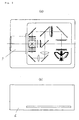
- Fig. 1 shows a liquid crystal display projector in an exemplary embodiment of the present invention when electric power is turned on, including a diagram for explaining the optical system used in the projector.
- Fig. 1(a) is a plan view and Fig. 1(b) is a front view of the liquid crystal display projector.
- Fig. 2 is a diagram for explaining the optical system of the liquid crystal display projector of Fig. 1 when electric power is turned off.
- Fig. 2(a) is a plan view and Fig. 2(b) is a front view of the liquid crystal display projector.
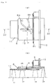
- Fig. 3 shows the structure of a projection lens zoomed for wide-angle projection as used in a liquid crystal display projector in an exemplary embodiment of the present invention.
- Fig. 3(a) is a plan view and Fig. 3(b) is a cross-sectional view of the projection lens.
- Fig. 4 shows the structure of a projection lens zoomed for close-up projection as used in a liquid crystal display projector in an exemplary embodiment of the present invention.
- Fig. 4(a) is a plan view and Fig. 4(b) is a cross-sectional view of the projection lens.
- Fig. 5 shows the structure of a projection lens as used in a liquid crystal display projector in an exemplary embodiment of the present invention when electric power is turned off.
- Fig. 5(a) is a plan view and Fig. 5(b) is a cross-sectional view of the projection lens.
- Fig. 6 is a plan view of a prior art liquid crystal display projector for explaining the optical system thereof.
- Fig. 1 shows the main body of a 3-panel type liquid crystal display projector in an exemplary embodiment of the present invention when electric power is turned on and a diagram of the whole optical system used in the projector.
- Fig. 1(a) is a plan view and Fig. 1(b) is a front view of the liquid crystal display projector.
- Fig. 2 shows how the projector's main body looks like when electric power is turned off.
- Fig. 2(a) is a plan view and Fig. 2(b) is a front view of the projector.
- Fig. 3 to Fig. 5 show the structure only of a projection lens as used in the liquid crystal display projector in the present exemplary embodiment.
- Fig. 1 shows the main body of a 3-panel type liquid crystal display projector in an exemplary embodiment of the present invention when electric power is turned on and a diagram of the whole optical system used in the projector.
- Fig. 1(a) is a plan view and Fig. 1(b) is a front view
- FIG. 3 shows a state where in the projection lens is zoomed for wide-angle projection
- Fig. 4 shows a state wherein the projection lens is zoomed for close-up projection
- Fig. 5 shows a state of the projection lens when electric power is turned off.
- Fig. 3(a) to Fig. 5(a) are plan views of the projection lens in each respective state thereof as mentioned in the above.
- Fig. 3(b), Fig. 4(b) and Fig. 5(b) are partially sectional views of the projection lens looked in the directions as indicated by arrows S1, S2 and S3, respectively.
- the light emitted from a lamp 1 serving as a light source is split into red, green and blue colors by a plurality of mirrors 2.
- Each respective color light thus produced is incident on a corresponding liquid crystal panel 3 serving as a liquid crystal display device.
- all the lights of the images displayed in each respective color on the liquid crystal panels 3 are combined to form image lights in natural color by means of a prism 4 and the like.
- the composite image lights of natural color are projected on a screen to form enlarged images by a projection lens 5. All the components as mentioned above are contained inside of a main body cabinet 6.
- Each respective liquid crystal panel 3 is capable of forming images of light by means of a plurality of liquid crystal pixels, each of which is acting as a light valve to pass or block light.
- the projection lens 5 comprises:
- the rotation of the drive motor 9 causes the intermediate cylinder 8 to rotate and the rotation of the intermediate cylinder 8 causes the first inner cylinder 11 to move by sliding out of and sliding into the outer cylinder 10.
- the first inner cylinder 11 is provided with a first axis 14 which is insertable in the first cam groove 8a and the second inner cylinder 12 is provided with a second axis 15 which is insertable in the second cam groove 8b.
- the outer cylinder 10 is provided with a first elongated hole 10a, the length of which extends in the same direction as the first inner cylinder 11 slides.
- the first inner cylinder 11 is provided with a second elongated hole 11a at a position opposite to the first elongated hole 10a and the second axis 15 is inserted in the first elongated hole 10a running through the foregoing second elongated hole 11a.
- the first axis 14 is moved in the direction indicated by an arrow "X" as shown in Fig. 3 (a) along the the first elongated hole 10a according to the rotational positions of the first cam groove 8a.
- the first inner cylinder 11 with the first lens 13 (L1) and second lens 13 (L2) installed therein is moved in the direction as indicated by the arrow "X".
- the second inner cylinder 12 is also moved a little bit in the direction of the arrow "X" along the first elongated hole 10a of the outer cylinder 10 according to the rotational positions of the second cam groove 8b.
- the first inner cylinder 11 slides along the curving first cam groove 8a to get to a specified position and the second inner cylinder 12 slides along the curving second cam groove 8b to get to a specified position.
- the projection lens 5 is allowed to change positions thereof for zooming from wide-angle projection to close-up projection while the projection lens 5 rotating over an angle corresponding to a travel of the first axis 14 from a position "C" to position "D" along the first cam groove 8a.
- the first inner cylinder 11 retracts inside the outer cylinder 10 while the projection lens 5 rotating over an angle corresponding to a travel of the first axis 14 from a position "D" to position "E” along the first cam groove 8a.
- Fig. 3 shows the state of wide-angle projection, wherein the first inner cylinder 11 is protruding the most from the outer cylinder 10 of the projector's main body cabin 6.
- Fig. 4 shows the state of close-up projection, wherein the first inner cylinder is protruding a little bit from the outer cylinder 10 of the projector's main body cabin 6.
- the first inner cylinder 11 is retracting inside the outer cylinder 10 of the projector's main body cabin 6 and the second inner cylinder 12 is retracting in the further back inside the outer cylinder 10.
- the control of stopping angle for the drive motor 9 is made by means of a timing switch, which is not shown in the drawing.
- the entire projection lens 5 is housed inside the projector's main body cabin 6 as shown in Fig. 5.
- the first inner cylinder 11 protrudes from the main body cabin 6.
- the control of zooming drive for wide-angle projection and close-up projection is conducted by means of a specified mechanism, which is not shown in the drawings.
- the foregoing is not necessarily needed as far as the first inner cylinder 11 is allowed to protrude from the main body cabin 6.
- the first inner cylinder 11 protrudes from and retracts into the outer cylinder 10 and intermediate cylinder 8 by sliding.
- the projection lens 5 protrudes from and retracts into the main body 6.
- the second inner cylinder 12 placed inside of the intermediate cylinder 8 in the far back thereof. In this case, it is not necessary to form the elongated hole 11a on the surface of the first inner cylinder 11 and the second axis 15 is moved while being engaged in the first elongated hole 10a and second cam groove 8b.
Landscapes
- Chemical & Material Sciences (AREA)
- Crystallography & Structural Chemistry (AREA)
- Engineering & Computer Science (AREA)
- Multimedia (AREA)
- Signal Processing (AREA)
- Liquid Crystal (AREA)
- Projection Apparatus (AREA)
- Transforming Electric Information Into Light Information (AREA)
Abstract
A liquid crystal display projector of the present invention comprises a light source, a group of mirrors, liquid crystal display devices, a projection lens, a main body cabin containing the foregoing light source, group of mirrors, liquid crystal display devices and projection lens, and a mechanism whereby the afore-mentioned projection lens is allowed to retract into and protrude from the main body.
The foregoing projection lens comprises:
- an outer cylinder that includes a ring-like shape; a drive motor provided with a gear; a ring-like intermediate cylinder which has a first cam groove, second cam groove and gearwork that is provided on the exterior thereof with the gearwork meshing with the gear of the drive motor and is installed on the inner side of the outer cylinder so as to be made movable by sliding; a first inner cylinder which has a first axis to fit in the first cam groove and fits with the inner surface of the intermediate cylinder in the front part thereof so as to be made movable by sliding according to the movement of the first axis caused by the rotation of the first cam groove; a second inner cylinder which has a second axis to fit in the second cam groove and fits with the inner surface of the intermedate cylinder toward the back thereof so as to be made movable by sliding according to the movement of the second axis caused by the rotation of the second cam groove; and a plurality of lenses installed in the first inner cylinder, second inner cylinder, intermediate cylinder and outer cylinder at positions as specified in a given way.
Description
- The present invent ion relates to a liquid crystal display projector, whereby video images displayed on liquid crystal display panels and the like are projected on a screen.
- For many years by now, projectors using a metal halide lamp and the like as the light source, whereby video images displayed on liquid crystal panels are enlarged and projected on a screen, have been available on the market.
With such projectors, the light emitted from the light source is gathered on liquid crystal panels by means of mirrors and the like and projected on a screen through a projection lens.
There are two kinds of liquid crystal display projectors, one being a 1-panel type that employs one liquid crystal display panel and the other being a 3-panel type wherein three liquid crystal display panels are used and color splitting and color combining are performed by means of dichloic mirrors and the like.
Each respective type of the above has a projection lens protruding from the projector's main body cabinet. - As shown in Fig. 6, a 1-panel type liquid crystal display projector has, in general, a
projection lens 41, afield lens 42, a liquidcrystal display panel 43 andpolarizers 45 for light incident side and light radiant side.
There are two types in theprojection lens 41, one having a fixed focus length and the other having a zooming function.
A 3-panel type liquid crystal display projector is basically of the same structure except for havinghalf mirrors 44 that are additionally built in for color splitting and combining.
These types of liquid crystal display projectors were proposed in a Japanese patent application published for public examination, Showa 62(1987)-316710, for example. - Each respective liquid crystal display projector of 1-panel type and 3-panel type has generally a structure where in a projection lens protrudes from the main body cabinet of the projector due to limitations in layout.
The structure wherein the projection lens protrudes has often caused a problem of damaging the protruding lens and the like when a liquid crystal display projector is carried. In addition, the protruding projection lens has imposed many restrictions on designing liquid crystal display projectors, thereby leading to a reduction in freedom of design.
Furthermore, there is a drawback that dust easily settles on a protruding projection lens. - A liquid crystal display projector of the present invention comprises:
- a light source;
- a group of mirrors for splitting and combining the light from the light source;
- liquid crystal devices to control passage of the light;
- a projection lens with a function of zooming in or out the images of light passed and formed by the liquid crystal devices;
- a main body cabinet that contains the light source, group of mirrors, liquid crystal devices and projection lens; and
- a mechanism whereby an operation of protruding and retracting of the projection lens from and into the main body cabinet, respectively, is made possible.
- What is particularly preferred in the foregoing structure is to provide functions whereby:
- the projection lens retracts into the main body cabinet when electric power is turned off; and
- the projection lens protrudes from the main body cabinet when electric power is turned on.
- Further, what is particularly preferred in the foregoing structure is to make the projection lens comprise:
- a ring-like intermediate cylinder;
- a drive motor for driving the above intermediate cylinder;
- an outer cylinder that fits with the outer surface of the intermediate cylinder;
- an inner cylinder that fits with and is allowed to slide along the inner surface of the intermediate cylinder; and
- a plurality of lenses installed in at least one of the foregoing inner cylinder, intermediate cylinder and outer cylinder, and
- the above intermediate cylinder is rotated according to the rotation of the drive motor and the rotation of the intermediate cylinder causes the inner cylinder to slide out of or slide in the outer cylinder and intermediate cylinder, thus enabling the operation of protruding and retracting of the projection lens as described in the above.
- Still further, what is particularly preferred in the foregoing structure is to make the projection lens comprise:
- a ring-like intermediate cylinder having a first cam groove, second cam groove and gearwork that is provided on the exterior thereof;
- an outer cylinder that fits with the outer surface of the intermediate cylinder and has a drive motor with a gear to mesh with the foregoing gearwork of the intermediate cylinder;
- a first inner cylinder that has a first axis to fit in the above first cam groove and fits with the inner surface of the above intermediate cylinder, yet allowed to slide along the inner surface of the intermediate cylinder according to the movement of the first axis caused by the rotation of the first cam groove;
- a second inner cylinder that has a second axis to fit in the above second cam groove and fits with the inner surface of the above intermediate cylinder, yet allowed to slide along the inner surface of the intermediate cylinder according to the movement of the second axis caused by the rotation of the second cam groove; and
- a plurality of lenses installed in the foregoing first inner cylinder, second inner cylinder, intermediate cylinder and outer cylinder as designated for installation of lenses in accordance with a given specification.
- Still further, what is particularly preferred in the foregoing structure is to have the outer cylinder provided with a first elongated hole extending in length in the sliding direction thereof and the first inner cylinder provided with a second elongated hole extending in length in the sliding direction thereof.
Accordingly, the intermediate cylinder is rotated according to the rotation of the drive motor and the rotation of the intermediate cylinder causes the afore-mentioned first axis to move along the first elongated hole.
As a result, the inner cylinder moves by sliding out of and sliding into the outer cylinder. - With each respective structure as described in the above, no lenses are protruding from the main body cabinet of a liquid crystal display projector when the projector is carried, thereby eliminating dangers to damage lenses.
Furthermore, the main body cabinet of a liquid crystal display projector can be made simple in design, looking like a rectangular prism that is similar to the configuration of a suit case. In addition, such a novel design as a door provided in front of the projection lens side of a liquid crystal display projector is possible, for example.
Thus, production of liquid crystal display projectors having whatever designs as desired is now possible. - Fig. 1 shows a liquid crystal display projector in an exemplary embodiment of the present invention when electric power is turned on, including a diagram for explaining the optical system used in the projector.
Fig. 1(a) is a plan view and Fig. 1(b) is a front view of the liquid crystal display projector. - Fig. 2 is a diagram for explaining the optical system of the liquid crystal display projector of Fig. 1 when electric power is turned off. Fig. 2(a) is a plan view and Fig. 2(b) is a front view of the liquid crystal display projector.
- Fig. 3 shows the structure of a projection lens zoomed for wide-angle projection as used in a liquid crystal display projector in an exemplary embodiment of the present invention. Fig. 3(a) is a plan view and Fig. 3(b) is a cross-sectional view of the projection lens.
- Fig. 4 shows the structure of a projection lens zoomed for close-up projection as used in a liquid crystal display projector in an exemplary embodiment of the present invention. Fig. 4(a) is a plan view and Fig. 4(b) is a cross-sectional view of the projection lens.
- Fig. 5 shows the structure of a projection lens as used in a liquid crystal display projector in an exemplary embodiment of the present invention when electric power is turned off. Fig. 5(a) is a plan view and Fig. 5(b) is a cross-sectional view of the projection lens.
- Fig. 6 is a plan view of a prior art liquid crystal display projector for explaining the optical system thereof.
-
- 1
- Light Source
- 2
- Mirror
- 3
- Liquid Crystal Panel
- 4
- Prism
- 5
- Projection Lens
- 6
- Main Body Cabinet
- 8
- Intermediate Cylinder
- 8a
- First Cam Groove
- 8b
- Second Cam Groove
- 8c
- Gearwork
- 10
- Outer Cylinder
- 10a
- First Elongated Hole
- 11
- First Inner Cylinder
- 11a
- Second Elongated Cylinder
- 12
- Second Inner Cylinder
- 13
- Group of Lenses
- 13(L1)
- First Lens
- 13(L2)
- Second Lens
- 13(L3)
- Third Lens
- 13(L4)
- Fourth Lens
- 14
- First Axis
- 15
- Second Axis
- Next, a few exemplary embodiments of the present invention will be explained with reference to Fig. 1 through Fig. 5.
- Fig. 1 shows the main body of a 3-panel type liquid crystal display projector in an exemplary embodiment of the present invention when electric power is turned on and a diagram of the whole optical system used in the projector.
Fig. 1(a) is a plan view and Fig. 1(b) is a front view of the liquid crystal display projector.
Fig. 2 shows how the projector's main body looks like when electric power is turned off. Fig. 2(a) is a plan view and Fig. 2(b) is a front view of the projector.
Fig. 3 to Fig. 5 show the structure only of a projection lens as used in the liquid crystal display projector in the present exemplary embodiment.
Fig. 3 shows a state where in the projection lens is zoomed for wide-angle projection, Fig. 4 shows a state wherein the projection lens is zoomed for close-up projection and Fig. 5 shows a state of the projection lens when electric power is turned off.
Fig. 3(a) to Fig. 5(a) are plan views of the projection lens in each respective state thereof as mentioned in the above.
Fig. 3(b), Fig. 4(b) and Fig. 5(b) are partially sectional views of the projection lens looked in the directions as indicated by arrows S1, S2 and S3, respectively. - As illustrated in Fig. 1, the light emitted from a
lamp 1 serving as a light source is split into red, green and blue colors by a plurality ofmirrors 2.
Each respective color light thus produced is incident on a correspondingliquid crystal panel 3 serving as a liquid crystal display device.
Then, all the lights of the images displayed in each respective color on theliquid crystal panels 3 are combined to form image lights in natural color by means of aprism 4 and the like.
The composite image lights of natural color are projected on a screen to form enlarged images by aprojection lens 5. All the components as mentioned above are contained inside of amain body cabinet 6.
Each respectiveliquid crystal panel 3 is capable of forming images of light by means of a plurality of liquid crystal pixels, each of which is acting as a light valve to pass or block light. - The
projection lens 5 comprises: - an
intermediate cylinder 8 with a ring-like cross-section; - a
drive motor 9 serving as a driving means to move theintermediate cylinder 8; - an
outer cylinder 10 fitted with the outer surface of theintermediate cylinder 8; - a first inner cylinder 11 fitted with and yet capable of sliding on the inner surface of the
intermediate cylinder 8; - a second
inner cylinder 12 installed in the back inside of the first cylinder 11 to slide on the inner surface thereof; - and a plurality of
lenses 13 mounted on the first inner cylinder 11, secondinner cylinder 12,intermediate cylinder 8 andouter cylinder 10 at specified positions thereof. - According to the foregoing structure, the rotation of the
drive motor 9 causes theintermediate cylinder 8 to rotate and the rotation of theintermediate cylinder 8 causes the first inner cylinder 11 to move by sliding out of and sliding into theouter cylinder 10. - Next, a more detailed explanation will be made on the present exemplary embodiment.
- The first inner cylinder 11 is provided with a
first axis 14 which is insertable in the first cam groove 8a and the secondinner cylinder 12 is provided with asecond axis 15 which is insertable in the second cam groove 8b.
Theouter cylinder 10 is provided with a first elongated hole 10a, the length of which extends in the same direction as the first inner cylinder 11 slides.
The first inner cylinder 11 is provided with a second elongated hole 11a at a position opposite to the first elongated hole 10a and thesecond axis 15 is inserted in the first elongated hole 10a running through the foregoing second elongated hole 11a.
When thedrive motor 9 runs, theintermediate cylinder 8 is rotated over a specified angle.
At this time, thefirst axis 14 is moved in the direction indicated by an arrow "X" as shown in Fig. 3 (a) along the the first elongated hole 10a according to the rotational positions of the first cam groove 8a.
As a result, the first inner cylinder 11 with the first lens 13 (L1) and second lens 13 (L2) installed therein is moved in the direction as indicated by the arrow "X".
In the same way as above, the secondinner cylinder 12 is also moved a little bit in the direction of the arrow "X" along the first elongated hole 10a of theouter cylinder 10 according to the rotational positions of the second cam groove 8b. - An explanation on the fourth lens 13 (L4) installed inside the
outer cylinder 10 is omitted since it has nothing to do with the operation of the present invention's projector. - Interlocking with the rotation of the
intermediate cylinder 8 made over a specified angle when the drive motor runs, the first inner cylinder 11 slides along the curving first cam groove 8a to get to a specified position and the secondinner cylinder 12 slides along the curving second cam groove 8b to get to a specified position.
At this time, theprojection lens 5 is allowed to change positions thereof for zooming from wide-angle projection to close-up projection while theprojection lens 5 rotating over an angle corresponding to a travel of thefirst axis 14 from a position "C" to position "D" along the first cam groove 8a.
The first inner cylinder 11 retracts inside theouter cylinder 10 while theprojection lens 5 rotating over an angle corresponding to a travel of thefirst axis 14 from a position "D" to position "E" along the first cam groove 8a.
In other words, Fig. 3 shows the state of wide-angle projection, wherein the first inner cylinder 11 is protruding the most from theouter cylinder 10 of the projector'smain body cabin 6.
Fig. 4 shows the state of close-up projection, wherein the first inner cylinder is protruding a little bit from theouter cylinder 10 of the projector'smain body cabin 6.
In Fig. 5, the first inner cylinder 11 is retracting inside theouter cylinder 10 of the projector'smain body cabin 6 and the secondinner cylinder 12 is retracting in the further back inside theouter cylinder 10.
The control of stopping angle for thedrive motor 9 is made by means of a timing switch, which is not shown in the drawing. - According to the structure as described in the above, when electric power is turned off, the
entire projection lens 5 is housed inside the projector'smain body cabin 6 as shown in Fig. 5.
When electric power is turned on, the first inner cylinder 11 protrudes from themain body cabin 6.
The control of zooming drive for wide-angle projection and close-up projection is conducted by means of a specified mechanism, which is not shown in the drawings.
In the present exemplary embodiment, it is particularly preferred to have theouter cylinder 10 fixed to themain body cabin 6. However, the foregoing is not necessarily needed as far as the first inner cylinder 11 is allowed to protrude from themain body cabin 6. - In the foregoing, it is also possible to employ a structure wherein the second
inner cylinder 12, second cam groove 8b andsecond axis 15 are not in place.
In this case, the first inner cylinder 11 protrudes from and retracts into theouter cylinder 10 andintermediate cylinder 8 by sliding.
In other words, theprojection lens 5 protrudes from and retracts into themain body 6. - In the foregoing structure, it is also possible to have the second
inner cylinder 12 placed inside of theintermediate cylinder 8 in the far back thereof.
In this case, it is not necessary to form the elongated hole 11a on the surface of the first inner cylinder 11 and thesecond axis 15 is moved while being engaged in the first elongated hole 10a and second cam groove 8b. - According the structure disclosed by the present invention, the following effects can be achieved:
- When electric power is turned off, a projection lens does not protrude from a projector's main body cabin and is housed inside the main body cabin, thereby preventing lenses from becoming damaged when a liquid crystal display projector is carried.
Therefore, the rotation of the intermediate cylinder from a first position to a second position in the first cam groove of the intermediate cylinder causes the projection lens to zoom and the rotation of the intermediate cylinder from the second position to a third position in the first cam groove causes the first inner cylinder to slide inside of the outer cylinder.
The
The shape of the first cam groove 8a and second cam groove 8b is curving so that the first inner cylinder 11 and second
With the present exemplary embodiment, the first cam groove 8a and second cam groove 8b are curving in a direction slanting from the perimeter of the circular outer surface of the
The
The
With the present exemplary embodiment, the plurality of
Since dust is prevented from entering into the area where liquid crystal panels are installed, designing of a dust proof structure can be made simple.
In addition, a simple design of a rectangular prism like configuration that appears like a suit case becomes possible. Moreover, it becomes possible to design a liquid crystal display projector with a desired appearance, resulting in enhanced freedom of designing.
A simpler structure needed for an operation of protruding and retracting a projection lens contributes to a reduction in production cost.
Claims (10)
- A liquid crystal display projector comprising:a light source;a group of mirrors for splitting and combining light from said light source;liquid crystal devices to control passage of said light;a projection lens with a function of zooming in or out the images of light formed by said liquid crystal devices;a main body cabinet that contains said light source, group of mirrors, liquid crystal devices and projection lens; anda mechanism whereby protruding and retracting said projection lens from and into said main body cabinet are made possible, respectively.
- The liquid crystal display projector according to Claim 1, wherein said projection lens retracts into said main body cabin when electric power is turned off, and said projection lens protrudes from said main body cabin when electric power is turned on.
- The liquid crystal display projector according to Claim 1, wherein said projection lens comprises:a ring-like intermediate cylinder;a driving means for rotating said intermediate cylinder;an outer cylinder that fits with the outer surface of said intermediate cylinder;an inner cylinder that fits with and is allowed to slide along the inner surface of said intermediate cylinder; anda plurality of lenses installed at least in one of said inner cylinder, intermediate cylinder and outer cylinder, and
wherein said intermediate cylinder is rotated by said driving means, andsaid inner cylinder is moved by sliding in said manner of protruding from and retracting into said outer cylinder according to the rotation of said intermediate cylinder. - The liquid crystal display projector according to Claim 1, wherein said outer cylinder is fixed to said main body cabinet, and the tip end of said outer cylinder does not protrude from said main body cabinet.
- The liquid crystal display projector according to Claim 1, wherein said projection lens comprises:an outer cylinder that includes a ring-like shape;a drive motor fixed to said outer cylinder and provided with a gear;a ring-like intermediate cylinder which has a first cam groove and gearwork to mesh with said gear and is installed on and made rotatable in the inner side of said outer cylinder;a first inner cylinder which has a first axis to fit in said first cam groove and fits with the inner surface of said intermediate cylinder so as to be allowed to slide back and forth therein according to the movement of said first axis caused by the rotation of said first cam groove; anda plurality of lenses installed in at least one of said first inner cylinder, intermediate cylinder and outer cylinder, and
wherein said projection lens operates in such a manner that driving of said drive motor causes said intermediate cylinder to rotate, the rotation of said intermediate cylinder causes said first axis to move along said first cam groove while keeping a good fit therewith, and the movement of said first axis causes said first inner cylinder to protrude from and retracting into said outer cylinder. - The liquid crystal display projector according to Claim 1, wherein said first cam groove has a first position, second position and third position in this order,
as said first axis moves from said first position to second position of said first cam groove, said projection lens is zoomed while said projection lens staying under said protruding state, and
as said first axis moves from said second position to third position, said first inner cylinder slides into the inside of said outer cylinder. - The liquid crystal display projector according to Claim 5, wherein said outer cylinder has a first elongated hole extending in length in said sliding direction on the outer surface thereof,rotation of said drive motor causes said intermediate cylinder to rotate,as said intermediate cylinder rotates, said first axis is moved along said first elongated hole, andthereby said first inner cylinder being allowed to slide along the inner side surface of said intermediate cylinder and to perform said protruding from and retracting into the inside of said intermediate cylinder.
- The liquid crystal display projector according to Claim 1, wherein said projection lens comprises:an outer cylinder that includes a ring-like shape;a drive motor fixed to said outer cylinder and provided with a gear;a ring-like intermediate cylinder which has a first cam groove, second cam groove and gear work that is provided on the exterior thereof with said gearwork meshing with said gear and is installed on the inner side of said outer cylinder so as to be made movable by sliding;a first inner cylinder which has a first axis to fit in said first cam groove and fits with the inner surface of said intermediate cylinder in the front part thereof so as to be made movable by sliding according to the movement of said first axis caused by the rotation of said first cam groove;a second inner cylinder which has a second axis to fit in said second cam groove and fits with the inner surface of said intermediate cylinder toward the back thereof so as to be made movable by sliding according to the movement of said second axis caused by the rotation of said second cam groove; anda plurality of lenses installed in at least one of said first inner cylinder, intermediate cylinder and outer cylinder, and
wherein said projection lens operates in such a manner that driving of said drive motor causes said intermediate cylinder to rotate, the rotation of said intermediate cylinder from said first position to second position of said first cam groove causes said projection lens to be zoomed while said projection lens staying under said protruding state and the rotation of said intermediate cylinder from said second position to third position of said first cam groove causes said first inner cylinder to slide inside of said outer cylinder. - The liquid crystal display projector according to Claim 8, wherein said outer cylinder has a first elongated hole extending in length in said sliding direction on the surface thereof,said second inner cylinder is installed inside of said first inner cylinder, andsaid first inner cylinder has a second elongated hole with a stretched length formed on the surface thereof at a position opposing to said first cam groove,
wherein rotation of said drive motor causes said intermedite cylinder to rotate and, as said intermediate cylinder rotates, said first axis is moved along said first elongated hole and said second axis is moved along said second elongated hole and first elongated hole,thereby said first inner cylinder being made to slide along the inner side surface of said intermediate cylinder and said second inner cylinder being made to slide along the inner side surface of said first inner cylinder so that said first inner cylinder performs said protruding from and retracting into the inside of said intermediate cylinder. - The liquid crystal display projector according to Claim 8, wherein said outer cylinder has a first elongated hole extending in length in said sliding direction on the surface thereof,said second inner cylinder is installed inside of said intermediate cylinder toward the back thereof,rotation of said drive motor causes said intermediate cylinder to rotate,as said intermediate cylinder rotates, said first axis and second axis are moved along said first elongated hole,thereby said first inner cylinder and second cylinder moving by sliding along the inner side surface of said intermediate cylinder so that said first inner cylinder performs said protruding from and retracting into the inside of said intermediate cylinder.
Applications Claiming Priority (6)
| Application Number | Priority Date | Filing Date | Title |
|---|---|---|---|
| JP105050/96 | 1996-04-25 | ||
| JP10505096 | 1996-04-25 | ||
| JP10505096 | 1996-04-25 | ||
| JP33176196A JP3331888B2 (en) | 1996-04-25 | 1996-12-12 | LCD projection equipment |
| JP331761/96 | 1996-12-12 | ||
| JP33176196 | 1996-12-12 |
Publications (3)
| Publication Number | Publication Date |
|---|---|
| EP0804027A2 true EP0804027A2 (en) | 1997-10-29 |
| EP0804027A3 EP0804027A3 (en) | 1999-07-14 |
| EP0804027B1 EP0804027B1 (en) | 2002-07-24 |
Family
ID=26445406
Family Applications (1)
| Application Number | Title | Priority Date | Filing Date |
|---|---|---|---|
| EP97106733A Expired - Lifetime EP0804027B1 (en) | 1996-04-25 | 1997-04-23 | Liquid crystal display projector |
Country Status (4)
| Country | Link |
|---|---|
| US (1) | US5868483A (en) |
| EP (1) | EP0804027B1 (en) |
| JP (1) | JP3331888B2 (en) |
| DE (1) | DE69714131T2 (en) |
Cited By (3)
| Publication number | Priority date | Publication date | Assignee | Title |
|---|---|---|---|---|
| EP1263223A2 (en) * | 2001-05-30 | 2002-12-04 | Fuji Photo Optical Co., Ltd. | Projector device |
| CN101551582B (en) * | 2008-04-02 | 2012-01-25 | 青岛海信电器股份有限公司 | Projector |
| CN110049641A (en) * | 2018-01-16 | 2019-07-23 | 孙俊华 | A kind of ultrashort out-of-focus projection's instrument cabinet |
Families Citing this family (6)
| Publication number | Priority date | Publication date | Assignee | Title |
|---|---|---|---|---|
| AU769428B2 (en) * | 1999-01-29 | 2004-01-29 | Matsushita Electric Industrial Co., Ltd. | Liquid crystal projector |
| TW387566U (en) * | 1999-03-19 | 2000-04-11 | Acer Peripherals Inc | Projection-display apparatus with adjustable brightness and uniformity |
| JP2001092009A (en) * | 1999-09-17 | 2001-04-06 | Sony Corp | Projector device |
| CN101661151B (en) * | 2008-08-27 | 2012-03-14 | 鸿富锦精密工业(深圳)有限公司 | Projector |
| JP6648242B1 (en) | 2018-11-13 | 2020-02-14 | 富士フイルム株式会社 | Projection device |
| JP6650069B1 (en) * | 2019-10-15 | 2020-02-19 | 富士フイルム株式会社 | Projection device |
Citations (4)
| Publication number | Priority date | Publication date | Assignee | Title |
|---|---|---|---|---|
| US4018520A (en) * | 1975-04-15 | 1977-04-19 | Gaf Corporation | Projector focusing mechanism |
| GB2259828A (en) * | 1991-09-18 | 1993-03-24 | Toshiba Kk | Television projection display system with zoom-controlled on-screen display function |
| US5347324A (en) * | 1991-06-27 | 1994-09-13 | Fuji Photo Film Co., Ltd. | Video projector with battery and replaceable lamp unit |
| JPH0933880A (en) * | 1995-07-20 | 1997-02-07 | Fujitsu General Ltd | Liquid crystal projector |
Family Cites Families (6)
| Publication number | Priority date | Publication date | Assignee | Title |
|---|---|---|---|---|
| JPH04298731A (en) * | 1990-12-03 | 1992-10-22 | Sony Corp | Portable projector |
| WO1992015041A1 (en) * | 1991-02-22 | 1992-09-03 | Seiko Epson Corporation | Projection-type liquid crystalline projector |
| JP3348732B2 (en) * | 1992-04-10 | 2002-11-20 | ソニー株式会社 | projector |
| JP3300963B2 (en) * | 1993-10-20 | 2002-07-08 | 富士写真光機株式会社 | Shooting lens mount mechanism |
| US5642927A (en) * | 1995-11-22 | 1997-07-01 | Lightware, Inc. | LCD projector with retractable projection lens assembly |
| US5669688A (en) * | 1996-06-07 | 1997-09-23 | Proxima Corporation | Display panel projector and method of using same |
-
1996
- 1996-12-12 JP JP33176196A patent/JP3331888B2/en not_active Ceased
-
1997
- 1997-04-23 EP EP97106733A patent/EP0804027B1/en not_active Expired - Lifetime
- 1997-04-23 DE DE69714131T patent/DE69714131T2/en not_active Expired - Fee Related
- 1997-04-24 US US08/845,500 patent/US5868483A/en not_active Expired - Lifetime
Patent Citations (4)
| Publication number | Priority date | Publication date | Assignee | Title |
|---|---|---|---|---|
| US4018520A (en) * | 1975-04-15 | 1977-04-19 | Gaf Corporation | Projector focusing mechanism |
| US5347324A (en) * | 1991-06-27 | 1994-09-13 | Fuji Photo Film Co., Ltd. | Video projector with battery and replaceable lamp unit |
| GB2259828A (en) * | 1991-09-18 | 1993-03-24 | Toshiba Kk | Television projection display system with zoom-controlled on-screen display function |
| JPH0933880A (en) * | 1995-07-20 | 1997-02-07 | Fujitsu General Ltd | Liquid crystal projector |
Non-Patent Citations (1)
| Title |
|---|
| PATENT ABSTRACTS OF JAPAN vol. 097, no. 006, 30 June 1997 & JP 09 033880 A (FUJITSU GENERAL LTD), 7 February 1997 * |
Cited By (4)
| Publication number | Priority date | Publication date | Assignee | Title |
|---|---|---|---|---|
| EP1263223A2 (en) * | 2001-05-30 | 2002-12-04 | Fuji Photo Optical Co., Ltd. | Projector device |
| EP1263223A3 (en) * | 2001-05-30 | 2004-09-22 | Fuji Photo Optical Co., Ltd. | Projector device |
| CN101551582B (en) * | 2008-04-02 | 2012-01-25 | 青岛海信电器股份有限公司 | Projector |
| CN110049641A (en) * | 2018-01-16 | 2019-07-23 | 孙俊华 | A kind of ultrashort out-of-focus projection's instrument cabinet |
Also Published As
| Publication number | Publication date |
|---|---|
| US5868483A (en) | 1999-02-09 |
| JP3331888B2 (en) | 2002-10-07 |
| EP0804027A3 (en) | 1999-07-14 |
| DE69714131T2 (en) | 2002-11-07 |
| JPH1010643A (en) | 1998-01-16 |
| EP0804027B1 (en) | 2002-07-24 |
| DE69714131D1 (en) | 2002-08-29 |
Similar Documents
| Publication | Publication Date | Title |
|---|---|---|
| US6072545A (en) | Video image rotating apparatus | |
| JP3238610B2 (en) | Lens support structure | |
| US5868483A (en) | Liquid crystal display projector | |
| JP3182945B2 (en) | Multi-screen projection monitor | |
| EP1211901A2 (en) | Aperture element for a video projector and a video projector using the aperture element | |
| CN111698495B (en) | Binocular camera | |
| JP2594825Y2 (en) | Light blocking device for lens barrel | |
| JP2004279888A (en) | Display device | |
| CN213365248U (en) | Projection system | |
| CN1701615A (en) | Sequential display system with changing color order | |
| JP2593877Y2 (en) | Zoom lens camera with screen size switching mechanism | |
| JP3123723B2 (en) | Barrel light blocking structure of lens shutter camera with built-in zoom lens | |
| JP3078392B2 (en) | Multiple image display device | |
| KR100609181B1 (en) | Projection TV | |
| KR100229532B1 (en) | Projection television | |
| JP2616079B2 (en) | Projection tv | |
| JP2596880Y2 (en) | Shielding device for zoom lens camera | |
| RU20802U1 (en) | ADVERTISING AND INFORMATION MOBILE DEVICE | |
| JPH01200795A (en) | Color picture projection device | |
| JPH05249430A (en) | Liquid crystal video projection device and method for switching projection picture | |
| JP2007079181A (en) | High-definition digital micro device | |
| KR20050076883A (en) | Lighting optical system of display using the micro device | |
| JPH10133278A (en) | Optical image projecting device | |
| JPH04133039A (en) | Lighting bright frame finder | |
| JPH06337394A (en) | Liquid crystal projector |
Legal Events
| Date | Code | Title | Description |
|---|---|---|---|
| PUAI | Public reference made under article 153(3) epc to a published international application that has entered the european phase |
Free format text: ORIGINAL CODE: 0009012 |
|
| AK | Designated contracting states |
Kind code of ref document: A2 Designated state(s): DE FR GB |
|
| RIN1 | Information on inventor provided before grant (corrected) |
Inventor name: HOSHINO, MAKOTO Inventor name: HASHIMUKAI, MASANARI Inventor name: AONO, SHOZO Inventor name: OKADA, TAKEHIRO |
|
| PUAL | Search report despatched |
Free format text: ORIGINAL CODE: 0009013 |
|
| AK | Designated contracting states |
Kind code of ref document: A3 Designated state(s): DE FR GB |
|
| 17P | Request for examination filed |
Effective date: 19991110 |
|
| 17Q | First examination report despatched |
Effective date: 20001102 |
|
| GRAG | Despatch of communication of intention to grant |
Free format text: ORIGINAL CODE: EPIDOS AGRA |
|
| GRAG | Despatch of communication of intention to grant |
Free format text: ORIGINAL CODE: EPIDOS AGRA |
|
| GRAH | Despatch of communication of intention to grant a patent |
Free format text: ORIGINAL CODE: EPIDOS IGRA |
|
| GRAH | Despatch of communication of intention to grant a patent |
Free format text: ORIGINAL CODE: EPIDOS IGRA |
|
| GRAA | (expected) grant |
Free format text: ORIGINAL CODE: 0009210 |
|
| AK | Designated contracting states |
Kind code of ref document: B1 Designated state(s): DE FR GB |
|
| REG | Reference to a national code |
Ref country code: GB Ref legal event code: FG4D |
|
| REF | Corresponds to: |
Ref document number: 69714131 Country of ref document: DE Date of ref document: 20020829 |
|
| ET | Fr: translation filed | ||
| PLBE | No opposition filed within time limit |
Free format text: ORIGINAL CODE: 0009261 |
|
| STAA | Information on the status of an ep patent application or granted ep patent |
Free format text: STATUS: NO OPPOSITION FILED WITHIN TIME LIMIT |
|
| 26N | No opposition filed |
Effective date: 20030425 |
|
| PGFP | Annual fee paid to national office [announced via postgrant information from national office to epo] |
Ref country code: FR Payment date: 20080312 Year of fee payment: 12 Ref country code: DE Payment date: 20080502 Year of fee payment: 12 |
|
| PGFP | Annual fee paid to national office [announced via postgrant information from national office to epo] |
Ref country code: GB Payment date: 20080423 Year of fee payment: 12 |
|
| GBPC | Gb: european patent ceased through non-payment of renewal fee |
Effective date: 20090423 |
|
| REG | Reference to a national code |
Ref country code: FR Ref legal event code: ST Effective date: 20091231 |
|
| PG25 | Lapsed in a contracting state [announced via postgrant information from national office to epo] |
Ref country code: DE Free format text: LAPSE BECAUSE OF NON-PAYMENT OF DUE FEES Effective date: 20091103 |
|
| PG25 | Lapsed in a contracting state [announced via postgrant information from national office to epo] |
Ref country code: GB Free format text: LAPSE BECAUSE OF NON-PAYMENT OF DUE FEES Effective date: 20090423 Ref country code: FR Free format text: LAPSE BECAUSE OF NON-PAYMENT OF DUE FEES Effective date: 20091222 |