EP0814557A1 - Device for recharging the batteries of an electric vehicle - Google Patents
Device for recharging the batteries of an electric vehicle Download PDFInfo
- Publication number
- EP0814557A1 EP0814557A1 EP97401386A EP97401386A EP0814557A1 EP 0814557 A1 EP0814557 A1 EP 0814557A1 EP 97401386 A EP97401386 A EP 97401386A EP 97401386 A EP97401386 A EP 97401386A EP 0814557 A1 EP0814557 A1 EP 0814557A1
- Authority
- EP
- European Patent Office
- Prior art keywords
- inductor
- vehicle
- housing
- enclosing
- batteries
- Prior art date
- Legal status (The legal status is an assumption and is not a legal conclusion. Google has not performed a legal analysis and makes no representation as to the accuracy of the status listed.)
- Granted
Links
Images

Classifications
-
- B—PERFORMING OPERATIONS; TRANSPORTING
- B60—VEHICLES IN GENERAL
- B60L—PROPULSION OF ELECTRICALLY-PROPELLED VEHICLES; SUPPLYING ELECTRIC POWER FOR AUXILIARY EQUIPMENT OF ELECTRICALLY-PROPELLED VEHICLES; ELECTRODYNAMIC BRAKE SYSTEMS FOR VEHICLES IN GENERAL; MAGNETIC SUSPENSION OR LEVITATION FOR VEHICLES; MONITORING OPERATING VARIABLES OF ELECTRICALLY-PROPELLED VEHICLES; ELECTRIC SAFETY DEVICES FOR ELECTRICALLY-PROPELLED VEHICLES
- B60L53/00—Methods of charging batteries, specially adapted for electric vehicles; Charging stations or on-board charging equipment therefor; Exchange of energy storage elements in electric vehicles
- B60L53/30—Constructional details of charging stations
- B60L53/302—Cooling of charging equipment
-
- B—PERFORMING OPERATIONS; TRANSPORTING
- B60—VEHICLES IN GENERAL
- B60L—PROPULSION OF ELECTRICALLY-PROPELLED VEHICLES; SUPPLYING ELECTRIC POWER FOR AUXILIARY EQUIPMENT OF ELECTRICALLY-PROPELLED VEHICLES; ELECTRODYNAMIC BRAKE SYSTEMS FOR VEHICLES IN GENERAL; MAGNETIC SUSPENSION OR LEVITATION FOR VEHICLES; MONITORING OPERATING VARIABLES OF ELECTRICALLY-PROPELLED VEHICLES; ELECTRIC SAFETY DEVICES FOR ELECTRICALLY-PROPELLED VEHICLES
- B60L1/00—Supplying electric power to auxiliary equipment of vehicles
- B60L1/02—Supplying electric power to auxiliary equipment of vehicles to electric heating circuits
- B60L1/04—Supplying electric power to auxiliary equipment of vehicles to electric heating circuits fed by the power supply line
- B60L1/06—Supplying electric power to auxiliary equipment of vehicles to electric heating circuits fed by the power supply line using only one supply
-
- B—PERFORMING OPERATIONS; TRANSPORTING
- B60—VEHICLES IN GENERAL
- B60L—PROPULSION OF ELECTRICALLY-PROPELLED VEHICLES; SUPPLYING ELECTRIC POWER FOR AUXILIARY EQUIPMENT OF ELECTRICALLY-PROPELLED VEHICLES; ELECTRODYNAMIC BRAKE SYSTEMS FOR VEHICLES IN GENERAL; MAGNETIC SUSPENSION OR LEVITATION FOR VEHICLES; MONITORING OPERATING VARIABLES OF ELECTRICALLY-PROPELLED VEHICLES; ELECTRIC SAFETY DEVICES FOR ELECTRICALLY-PROPELLED VEHICLES
- B60L53/00—Methods of charging batteries, specially adapted for electric vehicles; Charging stations or on-board charging equipment therefor; Exchange of energy storage elements in electric vehicles
- B60L53/10—Methods of charging batteries, specially adapted for electric vehicles; Charging stations or on-board charging equipment therefor; Exchange of energy storage elements in electric vehicles characterised by the energy transfer between the charging station and the vehicle
- B60L53/12—Inductive energy transfer
-
- B—PERFORMING OPERATIONS; TRANSPORTING
- B60—VEHICLES IN GENERAL
- B60L—PROPULSION OF ELECTRICALLY-PROPELLED VEHICLES; SUPPLYING ELECTRIC POWER FOR AUXILIARY EQUIPMENT OF ELECTRICALLY-PROPELLED VEHICLES; ELECTRODYNAMIC BRAKE SYSTEMS FOR VEHICLES IN GENERAL; MAGNETIC SUSPENSION OR LEVITATION FOR VEHICLES; MONITORING OPERATING VARIABLES OF ELECTRICALLY-PROPELLED VEHICLES; ELECTRIC SAFETY DEVICES FOR ELECTRICALLY-PROPELLED VEHICLES
- B60L53/00—Methods of charging batteries, specially adapted for electric vehicles; Charging stations or on-board charging equipment therefor; Exchange of energy storage elements in electric vehicles
- B60L53/30—Constructional details of charging stations
- B60L53/35—Means for automatic or assisted adjustment of the relative position of charging devices and vehicles
- B60L53/36—Means for automatic or assisted adjustment of the relative position of charging devices and vehicles by positioning the vehicle
-
- B—PERFORMING OPERATIONS; TRANSPORTING
- B60—VEHICLES IN GENERAL
- B60L—PROPULSION OF ELECTRICALLY-PROPELLED VEHICLES; SUPPLYING ELECTRIC POWER FOR AUXILIARY EQUIPMENT OF ELECTRICALLY-PROPELLED VEHICLES; ELECTRODYNAMIC BRAKE SYSTEMS FOR VEHICLES IN GENERAL; MAGNETIC SUSPENSION OR LEVITATION FOR VEHICLES; MONITORING OPERATING VARIABLES OF ELECTRICALLY-PROPELLED VEHICLES; ELECTRIC SAFETY DEVICES FOR ELECTRICALLY-PROPELLED VEHICLES
- B60L53/00—Methods of charging batteries, specially adapted for electric vehicles; Charging stations or on-board charging equipment therefor; Exchange of energy storage elements in electric vehicles
- B60L53/30—Constructional details of charging stations
- B60L53/35—Means for automatic or assisted adjustment of the relative position of charging devices and vehicles
- B60L53/37—Means for automatic or assisted adjustment of the relative position of charging devices and vehicles using optical position determination, e.g. using cameras
-
- B—PERFORMING OPERATIONS; TRANSPORTING
- B60—VEHICLES IN GENERAL
- B60L—PROPULSION OF ELECTRICALLY-PROPELLED VEHICLES; SUPPLYING ELECTRIC POWER FOR AUXILIARY EQUIPMENT OF ELECTRICALLY-PROPELLED VEHICLES; ELECTRODYNAMIC BRAKE SYSTEMS FOR VEHICLES IN GENERAL; MAGNETIC SUSPENSION OR LEVITATION FOR VEHICLES; MONITORING OPERATING VARIABLES OF ELECTRICALLY-PROPELLED VEHICLES; ELECTRIC SAFETY DEVICES FOR ELECTRICALLY-PROPELLED VEHICLES
- B60L53/00—Methods of charging batteries, specially adapted for electric vehicles; Charging stations or on-board charging equipment therefor; Exchange of energy storage elements in electric vehicles
- B60L53/30—Constructional details of charging stations
- B60L53/35—Means for automatic or assisted adjustment of the relative position of charging devices and vehicles
- B60L53/38—Means for automatic or assisted adjustment of the relative position of charging devices and vehicles specially adapted for charging by inductive energy transfer
-
- H—ELECTRICITY
- H02—GENERATION; CONVERSION OR DISTRIBUTION OF ELECTRIC POWER
- H02J—CIRCUIT ARRANGEMENTS OR SYSTEMS FOR SUPPLYING OR DISTRIBUTING ELECTRIC POWER; SYSTEMS FOR STORING ELECTRIC ENERGY
- H02J50/00—Circuit arrangements or systems for wireless supply or distribution of electric power
- H02J50/10—Circuit arrangements or systems for wireless supply or distribution of electric power using inductive coupling
-
- H—ELECTRICITY
- H02—GENERATION; CONVERSION OR DISTRIBUTION OF ELECTRIC POWER
- H02J—CIRCUIT ARRANGEMENTS OR SYSTEMS FOR SUPPLYING OR DISTRIBUTING ELECTRIC POWER; SYSTEMS FOR STORING ELECTRIC ENERGY
- H02J50/00—Circuit arrangements or systems for wireless supply or distribution of electric power
- H02J50/90—Circuit arrangements or systems for wireless supply or distribution of electric power involving detection or optimisation of position, e.g. alignment
-
- H—ELECTRICITY
- H02—GENERATION; CONVERSION OR DISTRIBUTION OF ELECTRIC POWER
- H02J—CIRCUIT ARRANGEMENTS OR SYSTEMS FOR SUPPLYING OR DISTRIBUTING ELECTRIC POWER; SYSTEMS FOR STORING ELECTRIC ENERGY
- H02J7/00—Circuit arrangements for charging or depolarising batteries or for supplying loads from batteries
- H02J7/0042—Circuit arrangements for charging or depolarising batteries or for supplying loads from batteries characterised by the mechanical construction
-
- B—PERFORMING OPERATIONS; TRANSPORTING
- B60—VEHICLES IN GENERAL
- B60L—PROPULSION OF ELECTRICALLY-PROPELLED VEHICLES; SUPPLYING ELECTRIC POWER FOR AUXILIARY EQUIPMENT OF ELECTRICALLY-PROPELLED VEHICLES; ELECTRODYNAMIC BRAKE SYSTEMS FOR VEHICLES IN GENERAL; MAGNETIC SUSPENSION OR LEVITATION FOR VEHICLES; MONITORING OPERATING VARIABLES OF ELECTRICALLY-PROPELLED VEHICLES; ELECTRIC SAFETY DEVICES FOR ELECTRICALLY-PROPELLED VEHICLES
- B60L2240/00—Control parameters of input or output; Target parameters
- B60L2240/10—Vehicle control parameters
- B60L2240/34—Cabin temperature
-
- B—PERFORMING OPERATIONS; TRANSPORTING
- B60—VEHICLES IN GENERAL
- B60L—PROPULSION OF ELECTRICALLY-PROPELLED VEHICLES; SUPPLYING ELECTRIC POWER FOR AUXILIARY EQUIPMENT OF ELECTRICALLY-PROPELLED VEHICLES; ELECTRODYNAMIC BRAKE SYSTEMS FOR VEHICLES IN GENERAL; MAGNETIC SUSPENSION OR LEVITATION FOR VEHICLES; MONITORING OPERATING VARIABLES OF ELECTRICALLY-PROPELLED VEHICLES; ELECTRIC SAFETY DEVICES FOR ELECTRICALLY-PROPELLED VEHICLES
- B60L2250/00—Driver interactions
- B60L2250/16—Driver interactions by display
-
- Y—GENERAL TAGGING OF NEW TECHNOLOGICAL DEVELOPMENTS; GENERAL TAGGING OF CROSS-SECTIONAL TECHNOLOGIES SPANNING OVER SEVERAL SECTIONS OF THE IPC; TECHNICAL SUBJECTS COVERED BY FORMER USPC CROSS-REFERENCE ART COLLECTIONS [XRACs] AND DIGESTS
- Y02—TECHNOLOGIES OR APPLICATIONS FOR MITIGATION OR ADAPTATION AGAINST CLIMATE CHANGE
- Y02T—CLIMATE CHANGE MITIGATION TECHNOLOGIES RELATED TO TRANSPORTATION
- Y02T10/00—Road transport of goods or passengers
- Y02T10/60—Other road transportation technologies with climate change mitigation effect
- Y02T10/70—Energy storage systems for electromobility, e.g. batteries
-
- Y—GENERAL TAGGING OF NEW TECHNOLOGICAL DEVELOPMENTS; GENERAL TAGGING OF CROSS-SECTIONAL TECHNOLOGIES SPANNING OVER SEVERAL SECTIONS OF THE IPC; TECHNICAL SUBJECTS COVERED BY FORMER USPC CROSS-REFERENCE ART COLLECTIONS [XRACs] AND DIGESTS
- Y02—TECHNOLOGIES OR APPLICATIONS FOR MITIGATION OR ADAPTATION AGAINST CLIMATE CHANGE
- Y02T—CLIMATE CHANGE MITIGATION TECHNOLOGIES RELATED TO TRANSPORTATION
- Y02T10/00—Road transport of goods or passengers
- Y02T10/60—Other road transportation technologies with climate change mitigation effect
- Y02T10/7072—Electromobility specific charging systems or methods for batteries, ultracapacitors, supercapacitors or double-layer capacitors
-
- Y—GENERAL TAGGING OF NEW TECHNOLOGICAL DEVELOPMENTS; GENERAL TAGGING OF CROSS-SECTIONAL TECHNOLOGIES SPANNING OVER SEVERAL SECTIONS OF THE IPC; TECHNICAL SUBJECTS COVERED BY FORMER USPC CROSS-REFERENCE ART COLLECTIONS [XRACs] AND DIGESTS
- Y02—TECHNOLOGIES OR APPLICATIONS FOR MITIGATION OR ADAPTATION AGAINST CLIMATE CHANGE
- Y02T—CLIMATE CHANGE MITIGATION TECHNOLOGIES RELATED TO TRANSPORTATION
- Y02T90/00—Enabling technologies or technologies with a potential or indirect contribution to GHG emissions mitigation
- Y02T90/10—Technologies relating to charging of electric vehicles
- Y02T90/12—Electric charging stations
-
- Y—GENERAL TAGGING OF NEW TECHNOLOGICAL DEVELOPMENTS; GENERAL TAGGING OF CROSS-SECTIONAL TECHNOLOGIES SPANNING OVER SEVERAL SECTIONS OF THE IPC; TECHNICAL SUBJECTS COVERED BY FORMER USPC CROSS-REFERENCE ART COLLECTIONS [XRACs] AND DIGESTS
- Y02—TECHNOLOGIES OR APPLICATIONS FOR MITIGATION OR ADAPTATION AGAINST CLIMATE CHANGE
- Y02T—CLIMATE CHANGE MITIGATION TECHNOLOGIES RELATED TO TRANSPORTATION
- Y02T90/00—Enabling technologies or technologies with a potential or indirect contribution to GHG emissions mitigation
- Y02T90/10—Technologies relating to charging of electric vehicles
- Y02T90/14—Plug-in electric vehicles
Landscapes
- Engineering & Computer Science (AREA)
- Power Engineering (AREA)
- Transportation (AREA)
- Mechanical Engineering (AREA)
- Computer Networks & Wireless Communication (AREA)
- Charge And Discharge Circuits For Batteries Or The Like (AREA)
- Electric Propulsion And Braking For Vehicles (AREA)
Abstract
Description
La présente invention concerne un dispositif pour recharger les batteries d'accumulateurs d'un véhicule électrique.The present invention relates to a device for recharging the storage batteries of an electric vehicle.
On connaît un tel dispositif comprenant un boîtier fixe d'une station fixe à plusieurs boîtiers fixes, le boîtier fixe enfermant un inducteur relié à un générateur haute fréquence alimenté par le secteur, et un boîtier fixé sur le véhicule contenant un récepteur d'énergie pouvant être placé au-dessus de l'inducteur de façon à permettre un transfert d'énergie inductive entre l'inducteur et le récepteur et à permettre ainsi la recharge des batteries du véhicule.Such a device is known comprising a fixed box of a fixed station with several fixed boxes, the fixed box enclosing an inductor connected to a high frequency generator supplied by the sector, and a box fixed to the vehicle containing an energy receiver which can be placed above the inductor so as to allow an inductive energy transfer between the inductor and the receiver and thus allow recharging of the vehicle batteries.
Cependant, ce genre de dispositif connu implique l'utilisation d'inducteurs fixes d'une station fixe, ce qui entraîne un certain nombre de contraintes, et essentiellement l'obligation de se rendre à certains endroits bien précis pour recharger les batteries d'un véhicule électrique. En fait, ce dispositif de rechargement connu est surtout valable dans le cas d'une flotte de véhicules ou d'un système de location de véhicules.However, this type of known device involves the use of fixed inductors from a fixed station, which involves a certain number of constraints, and essentially the obligation to go to certain very precise places to recharge the batteries of a electric vehicle. In fact, this known recharging device is especially valid in the case of a fleet of vehicles or a vehicle rental system.
Dans le cadre d'une utilisation privée, il est nécessaire de recharger les batteries du véhicule électrique en de nombreux endroits, selon les parcours effectués par le véhicule.In the case of private use, it is necessary to recharge the batteries of the electric vehicle in many places, depending on the journeys made by the vehicle.
L'invention a pour but de résoudre le problème ci-dessus en proposant un dispositif pour recharger les batteries d'accumulateurs d'un véhicule électrique, comprenant un boîtier placé sur le sol enfermant un inducteur relié à un générateur haute fréquence et un récepteur d'énergie fixé au véhicule et pouvant être placé au-dessus de l'inducteur de façon à permettre un transfert d'énergie inductive entre eux, et qui est caractérisé en ce que le boîtier enfermant l'inducteur est portatif.The invention aims to solve the above problem by providing a device for recharging the storage batteries of an electric vehicle, comprising a box placed on the ground enclosing an inductor connected to a high frequency generator and a receiver d energy attached to the vehicle and can be placed above the inductor to allow energy transfer inductive therebetween, and which is characterized in that the box enclosing the inductor is portable.
Avantageusement, le boîtier enfermant l'inducteur comprend des moyens de guidage du véhicule pour placer le récepteur au-dessus de l'inducteur.Advantageously, the box enclosing the inductor comprises means for guiding the vehicle to place the receiver above the inductor.
De préférence, les moyens de guidage comprennent une perche inclinable visible par le conducteur, reliée à un interrupteur du boîtier enfermant l'inducteur et déplaçable, sous la poussée du véhicule, entre une première position dans laquelle l'interrupteur coupe le transfert d'énergie inductive nécessaire pour recharger les batteries et une deuxième position dans laquelle l'interrupteur autorise le transfert d'énergie inductive pour recharger les batteries.Preferably, the guide means comprise a tilting pole visible by the driver, connected to a switch of the housing enclosing the inductor and movable, under the thrust of the vehicle, between a first position in which the switch cuts the transfer of energy inductive necessary to recharge the batteries and a second position in which the switch allows the transfer of inductive energy to recharge the batteries.
La perche est équipée à son extrémité libre supérieure d'un voyant lumineux, tel qu'une diode, pouvant s'allumer lors du basculement de l'interrupteur de la première position à la deuxième position pour faciliter le guidage du véhicule.The pole is equipped at its upper free end with an indicator light, such as a diode, which can light up when the switch switches from the first position to the second position to facilitate guiding the vehicle.
La perche est démontable.The pole is removable.
Les moyens de guidage comprennent également au moins un feu de guidage fixé au boîtier enfermant l'inducteur, en avant de la perche de guidage.The guide means also comprise at least one guide light fixed to the housing enclosing the inductor, in front of the guide pole.
Le véhicule électrique comprend un témoin, tel qu'un voyant lumineux, indiquant que le degré de recouvrement de l'inducteur et du récepteur est suffisant.The electric vehicle includes a warning light, such as an indicator light, indicating that the degree of overlap of the inductor and the receiver is sufficient.
Le boîtier enfermant l'inducteur est fixé amoviblement sur le sol et, de préférence, les moyens de fixation de ce boîtier comprennent une vis s'engageant dans une cheville placée dans le sol et éventuellement un cache antivol solidaire du boîtier et recouvrant la vis de fixation.The box enclosing the inductor is removably fixed on the ground and, preferably, the means for fixing this box comprise a screw engaging in a dowel placed in the ground and possibly an anti-theft cover secured to the housing and covering the fixing screw.
Le boîtier enfermant l'inducteur est équipé d'un câble d'alimentation électrique reliant le générateur haute fréquence au secteur d'alimentation et comprend un espace de rangement du câble d'alimentation.The box enclosing the inductor is equipped with an electric power cable connecting the high frequency generator to the power sector and includes a space for storing the power cable.
Enfin, le boîtier comprend des moyens de refroidissement, tels que des ailettes.Finally, the housing includes cooling means, such as fins.
L'invention sera mieux comprise et d'autres buts, caractéristiques, détails et avantages de celle-ci apparaîtront plus clairement au cours de la description explicative qui va suivre faite en référence aux dessins schématiques annexés donnés uniquement à titre d'exemple illustrant un mode de réalisation de l'invention et dans lesquels :The invention will be better understood and other objects, characteristics, details and advantages thereof will appear more clearly during the explanatory description which follows, made with reference to the appended schematic drawings given solely by way of example illustrating a mode of the invention and in which:
La figure 1 est une vue éclatée du boîtier portatif de l'invention faisant partie d'un dispositif pour recharger les batteries d'accumulateurs d'un véhicule électrique.Figure 1 is an exploded view of the portable housing of the invention forming part of a device for recharging the storage batteries of an electric vehicle.
La figure 2 est une vue en perspective du boîtier portatif en position assemblée.Figure 2 is a perspective view of the portable housing in the assembled position.
La figure 3 est une vue montrant le transport du boîtier portatif par une personne.Figure 3 is a view showing the transport of the portable housing by a person.
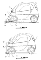
La figure 4 est une vue de côté montrant le guidage du véhicule électrique relativement au boîtier portatif placé sur le sol.Figure 4 is a side view showing the guidance of the electric vehicle relative to the portable housing placed on the ground.
La figure 5 montre le véhicule électrique dont le récepteur d'énergie est correctement placé au-dessus de l'inducteur du boîtier portatif placé sur le sol.FIG. 5 shows the electric vehicle, the energy receiver of which is correctly placed above the inductor of the portable box placed on the ground.
En se reportant aux figures 1 à 5, la référence 1 désigne un véhicule électrique sur lequel est monté à demeure un récepteur d'énergie 2 de préférence réalisé sous la forme d'un bobinage plan en spirale et pouvant être couplé électromagnétiquement à un inducteur 3 de préférence réalisé sous la forme d'un bobinage plan en spirale enfermé dans un boîtier 4 placé sur le sol, pour permettre le rechargement des batteries d'accumulateurs du véhicule 1. Comme cela est connu en soi, le récepteur d'énergie 2 est au moins en partie logé dans un boîtier diélectrique solidaire de la structure du véhicule 1 et est relié aux batteries de celui-ci par l'intermédiaire d'un circuit redresseur logé dans le véhicule.Referring to Figures 1 to 5, the reference 1 designates an electric vehicle on which is permanently mounted an
L'inducteur 3 est relié à un générateur haute fréquence logé dans le boîtier 4 comme on le verra ultérieurement et au secteur d'alimentation électrique par l'intermédiaire d'un câble d'alimentation 5.The
Lorsque le récepteur 2 recouvre correctement l'inducteur 3 en étant séparés l'un de l'autre d'une distance relativement courte de l'ordre de quelques centimètres, le récepteur 2 est couplé électromagnétiquement dans l'air à l'inducteur 3 de sorte qu'il intercepte le champ électromagnétique émis par l'inducteur 3 et la force électromotrice ainsi induite dans le récepteur 2 permet d'établir un courant de charge des batteries d'accumulateurs par l'intermédiaire d'un régulateur de charge (non représenté) relié entre le circuit redresseur et les batteries d'accumulateurs.When the
Selon l'invention, le boîtier 4 enfermant l'inducteur 3 est portatif et peut être éventuellement fixé sur le sol, à l'emplacement de parking du véhicule électrique 1, à l'aide d'une vis centrale de fixation 6 s'engageant dans une cheville anti-traction 7 implantée dans le sol de façon à solidariser au sol une plaque 4a constituant le fond du boîtier 4.According to the invention, the box 4 enclosing the
Le boîtier 4 comprend des moyens de guidage du véhicule 1 pour faciliter le placement du récepteur 2 au-dessus de l'inducteur 3.The box 4 comprises means for guiding the vehicle 1 to facilitate the placement of the
Ces moyens de guidage comprennent une perche inclinable 8 visible par le conducteur du véhicule 1, fixée amoviblement à un interrupteur 9 fixé sur le capot 4b du boîtier 4 et pouvant occuper soit une position de mise hors service d'un boîtier électronique 10 comprenant le générateur haute fréquence, de façon qu'aucun champ électromagnétique ne soit émis par l'inducteur 3, soit une position de mise en service du boîtier électronique 10 de façon que l'inducteur 3 puisse émettre le champ électromagnétique permettant la recharge des batteries d'accumulateurs du véhicule 1. Le boîtier électronique 10 et l'inducteur 3 sont logés dans le carter 4c du boîtier 4.These guide means comprise a tilting
La perche 8 est équipée à son extrémité libre supérieure d'un voyant lumineux 11, tel qu'une diode électroluminescente, pouvant s'allumer lors du basculement de l'interrupteur 9 de sa position de mise hors service du boîtier électronique 10 à sa position de mise en service de celui-ci.The
Les moyens de guidage peuvent également comporter au moins un feu de guidage 12 fixé au carter 4c du boîtier 4 en avant de celui-ci, en tout cas à l'opposé de l'interrupteur 9, de façon à être visible par le conducteur du véhicule électrique 1 lors de sa manoeuvre d'approche du boîtier 4.The guide means may also include at least one
Le câble d'alimentation 5 permettant de relier le générateur haute fréquence au secteur d'alimentation est logé dans un espace de rangement approprié du boîtier 4 qui comprend également des moyens de refroidissement, tels que des ailettes 13 de refroidissement par convection naturelle.The
Le cas échéant, afin de garantir l'inviolabilité du boîtier 4 fixé sur le sol, un cache antivol 14 est fixé dans une ouverture de forme conjuguée 15 du capot 4b de façon à empêcher l'accès à la vis de fixation 6.If necessary, in order to guarantee the inviolability of the box 4 fixed to the ground, an
L'utilisation du dispositif de l'invention ressort déjà de la description qui en a été faite ci-dessus et va être maintenant expliquée.The use of the device of the invention already emerges from the description which has been made above and will now be explained.
Tout d'abord, le conducteur du véhicule 1 installe le boîtier portatif 4 sur l'emplacement de parking du véhicule et, éventuellement, fixe ce boîtier sur le sol à l'aide de la vis centrale 6, puis fixe ensuite le cache antivol 14 au capot 4b du boîtier 4. Le conducteur branche ensuite le câble d'alimentation 5 sur le secteur et installe la perche 8 sur l'interrupteur 9 encastré dans le capot 4b.First of all, the driver of the vehicle 1 installs the portable box 4 on the parking space of the vehicle and, optionally, fixes this box on the ground using the central screw 6, then then fixes the
Ensuite, le conducteur avance son véhicule lentement vers le boîtier de recharge 4 en positionnant déjà le véhicule 1 relativement au boîtier 4 à l'aide du feu de guidage 12. Lorsque le véhicule 1 avance au-dessus du boîtier 4, il pousse la perche 8 de façon à basculer l'interrupteur 9 de sa position dans laquelle il coupe le transfert d'énergie inductive nécessaire pour recharger les batteries d'accumulateurs du véhicule à sa position dans laquelle il autorise ce transfert d'énergie inductive rechargeant les batteries d'accumulateurs. Lors de ce basculement, la diode électroluminescente 11, par exemple de couleur rouge, s'allume pour faciliter le guidage du véhicule. Le générateur haute fréquence étant alors mis en marche, crée le champ électromagnétique émis par l'inducteur 3 et intercepté par le récepteur 2. Dès qu'une partie suffisante d'énergie est captée par le récepteur 2, c'est-à-dire dès que le degré de recouvrement de l'inducteur 3 et du récepteur 2 est suffisant, un témoin 15 du véhicule 1, tel que par exemple un voyant lumineux, s'allume. Le conducteur arrête alors son véhicule et, à cet instant, la perche 8 est verticale. Les batteries d'accumulateurs du véhicule 1 commencent à se recharger. Une fois la recharge terminée, la diode rouge située au bout de la perche 8 s'éteint et le générateur haute fréquence est mis en veille. Lorsque le véhicule quitte le boîtier 4, la perche 8 est ramenée à sa position initiale pour couper le générateur haute fréquence. Si nécessaire, le conducteur peut désolidariser le boîtier 4 du sol et emmener celui-ci avec lui à l'aide de la poignée de manutention 4d comme cela ressort notamment de la figure 3 afin de permettre une recharge des batteries d'accumulateurs du véhicule à un autre endroit.Then, the driver advances his vehicle slowly towards the recharging unit 4, already positioning the vehicle 1 relative to the unit 4 using the
Le dispositif de l'invention permet également la recharge des batteries d'accumulateurs du véhicule qui se sont auto-déchargées au cours d'une longue période de non-utilisation. De plus, le dispositif de l'invention peut être utilisé pour réchauffer l'habitacle du véhicule sans utiliser les batteries d'accumulateurs de celui-ci.The device of the invention also makes it possible to recharge the vehicle's accumulator batteries which have self-discharged during a long period of non-use. In addition, the device of the invention can be used to heat the passenger compartment of the vehicle without using its storage batteries.
Les nombreux avantages déjà décrits ci-dessus du dispositif de l'invention et découlant de celui-ci comprennent en particulier :
- la facilité d'utilisation puisqu'aucun branchement n'est nécessaire,
- le centrage latéral du véhicule qui est assuré par le feu de guidage et la perche,
- le centrage longitudinal du véhicule sur l'inducteur grâce au témoin du niveau d'énergie captée,
- le boîtier compact et léger,
- la recharge possible des batteries d'accumulateurs même après une absence d'utilisation prolongée,
- l'alimentation des accessoires sur le secteur sans utiliser les batteries d'accumulateurs,
- le refroidissement par convection naturelle (sans ventilateur et sans bruit), et
- la possibilité de verrouiller le boîtier au sol.
- ease of use since no connection is necessary,
- the lateral centering of the vehicle which is ensured by the guide light and the pole,
- the longitudinal centering of the vehicle on the inductor thanks to the indicator of the level of energy captured,
- the compact and light housing,
- possible recharging of storage batteries even after prolonged non-use,
- supplying accessories to the mains without using accumulator batteries,
- natural convection cooling (without fan and noise), and
- the possibility of locking the box to the ground.
Claims (12)
Applications Claiming Priority (2)
| Application Number | Priority Date | Filing Date | Title |
|---|---|---|---|
| FR9607639 | 1996-06-19 | ||
| FR9607639A FR2750267B1 (en) | 1996-06-19 | 1996-06-19 | DEVICE FOR RECHARGING BATTERIES FROM AN ELECTRIC VEHICLE |
Publications (2)
| Publication Number | Publication Date |
|---|---|
| EP0814557A1 true EP0814557A1 (en) | 1997-12-29 |
| EP0814557B1 EP0814557B1 (en) | 2004-08-25 |
Family
ID=9493224
Family Applications (1)
| Application Number | Title | Priority Date | Filing Date |
|---|---|---|---|
| EP97401386A Expired - Lifetime EP0814557B1 (en) | 1996-06-19 | 1997-06-17 | Device for recharging the batteries of an electric vehicle |
Country Status (3)
| Country | Link |
|---|---|
| EP (1) | EP0814557B1 (en) |
| DE (1) | DE69730381D1 (en) |
| FR (1) | FR2750267B1 (en) |
Cited By (6)
| Publication number | Priority date | Publication date | Assignee | Title |
|---|---|---|---|---|
| EP0918390A2 (en) * | 1997-11-19 | 1999-05-26 | Ackermann Limited | Office workstation services |
| ES2181557A1 (en) * | 2000-11-27 | 2003-02-16 | Cisterra S L | Engine power supply system and battery recharge in electric vehicles |
| WO2003022671A3 (en) * | 2001-09-13 | 2003-08-21 | Sparta B V | Cycle with auxiliary propulsion |
| US20130088194A1 (en) * | 2011-08-16 | 2013-04-11 | Nucleus Scientific, Inc. | Overhead power transfer system |
| WO2013083625A1 (en) * | 2011-12-09 | 2013-06-13 | Bayerische Motoren Werke Aktiengesellschaft | Motor vehicle |
| CN108110842A (en) * | 2017-12-29 | 2018-06-01 | 宁夏软件工程院有限公司 | A kind of adaptive electric energy reception device |
Families Citing this family (3)
| Publication number | Priority date | Publication date | Assignee | Title |
|---|---|---|---|---|
| FR2962696B1 (en) | 2010-07-16 | 2016-07-01 | Renault Sa | NON-CONTACT CHARGE OF A MOTOR VEHICLE BATTERY. |
| EP2808976A1 (en) | 2013-05-29 | 2014-12-03 | Brusa Elektronik AG | Circuit assembly for the primary part of a system for contactless energy transfer, and transformer element |
| EP3065152A1 (en) | 2015-03-06 | 2016-09-07 | Brusa Elektronik AG | Primary section of an inductive charger |
Citations (3)
| Publication number | Priority date | Publication date | Assignee | Title |
|---|---|---|---|---|
| US3938018A (en) * | 1974-09-16 | 1976-02-10 | Dahl Ernest A | Induction charging system |
| US4347472A (en) * | 1980-10-20 | 1982-08-31 | Lemelson Jerome H | Apparatus and method for charging a battery in a vehicle |
| EP0586315A1 (en) * | 1992-09-02 | 1994-03-09 | Cableco | Assembly for recharging storage batteries of a electrically driven vehicle |
-
1996
- 1996-06-19 FR FR9607639A patent/FR2750267B1/en not_active Expired - Fee Related
-
1997
- 1997-06-17 EP EP97401386A patent/EP0814557B1/en not_active Expired - Lifetime
- 1997-06-17 DE DE69730381T patent/DE69730381D1/en not_active Expired - Lifetime
Patent Citations (3)
| Publication number | Priority date | Publication date | Assignee | Title |
|---|---|---|---|---|
| US3938018A (en) * | 1974-09-16 | 1976-02-10 | Dahl Ernest A | Induction charging system |
| US4347472A (en) * | 1980-10-20 | 1982-08-31 | Lemelson Jerome H | Apparatus and method for charging a battery in a vehicle |
| EP0586315A1 (en) * | 1992-09-02 | 1994-03-09 | Cableco | Assembly for recharging storage batteries of a electrically driven vehicle |
Cited By (9)
| Publication number | Priority date | Publication date | Assignee | Title |
|---|---|---|---|---|
| EP0918390A2 (en) * | 1997-11-19 | 1999-05-26 | Ackermann Limited | Office workstation services |
| EP0918390A3 (en) * | 1997-11-19 | 2000-03-22 | Ackermann Limited | Office workstation services |
| ES2181557A1 (en) * | 2000-11-27 | 2003-02-16 | Cisterra S L | Engine power supply system and battery recharge in electric vehicles |
| WO2003022671A3 (en) * | 2001-09-13 | 2003-08-21 | Sparta B V | Cycle with auxiliary propulsion |
| US20130088194A1 (en) * | 2011-08-16 | 2013-04-11 | Nucleus Scientific, Inc. | Overhead power transfer system |
| WO2013083625A1 (en) * | 2011-12-09 | 2013-06-13 | Bayerische Motoren Werke Aktiengesellschaft | Motor vehicle |
| CN103958245A (en) * | 2011-12-09 | 2014-07-30 | 宝马股份公司 | Motor vehicle |
| US9662992B2 (en) | 2011-12-09 | 2017-05-30 | Bayerische Motoren Werke Aktiengesellschaft | Motor vehicle having an inductive charging coil arranged on a lubricant reservoir of an internal combustion engine of the vehicle |
| CN108110842A (en) * | 2017-12-29 | 2018-06-01 | 宁夏软件工程院有限公司 | A kind of adaptive electric energy reception device |
Also Published As
| Publication number | Publication date |
|---|---|
| FR2750267B1 (en) | 1998-09-18 |
| DE69730381D1 (en) | 2004-09-30 |
| FR2750267A1 (en) | 1997-12-26 |
| EP0814557B1 (en) | 2004-08-25 |
Similar Documents
| Publication | Publication Date | Title |
|---|---|---|
| US3963972A (en) | Portable power package | |
| EP3472919B1 (en) | Portable device for paying out an electric cable, particularly a charging cable for an electric or hybrid vehicle | |
| CA2305228C (en) | Self-contained recharging device for portable telephone and/or battery and/or protective case | |
| EP0814557B1 (en) | Device for recharging the batteries of an electric vehicle | |
| EP0586315A1 (en) | Assembly for recharging storage batteries of a electrically driven vehicle | |
| FR2828787A1 (en) | ELECTRIC LAWN MOWER | |
| JP2000243458A (en) | Power pack charging system and power tool charging system | |
| EP0536056B1 (en) | Charging socket device for motorized electrical vehicle | |
| FR2732169A1 (en) | Recharging station for batteries of electric vehicles | |
| FR2613674A1 (en) | STORAGE BOX, DRAWER WITH MOBILE LAMP FOR AUTOMOBILE | |
| EP2710445B1 (en) | Protective case for a game console | |
| FR3093964A1 (en) | Autonomous and transportable carport to charge electric vehicles | |
| EP1363380A1 (en) | Generator for supplying a battery for portable device such as a mobile phone | |
| FR2992275A1 (en) | Vehicle i.e. hybrid vehicle, has management system determining location, point of time around location and point of time for charging and discharging location such that battery is completely charged up to desired minimum level | |
| EP0858172B1 (en) | Portable apparatus, and power pack for the portable apparatus capable of using different types of battery types | |
| EP1729392B1 (en) | Electric system onboard a motor vehicle | |
| FR3119347A1 (en) | Electric vehicle fitted with an adapter for recharging an electric battery. | |
| FR2988068A1 (en) | AUTOMATIC CYCLE STORAGE SYSTEM, CYCLE FOR SUCH A SYSTEM AND USE OF A BATTERY FOR SUCH A CYCLE. | |
| WO2012042179A2 (en) | Contactless charging of a motor vehicle battery | |
| FR2549297A1 (en) | SAFETY DEVICE FOR A RECHARGEABLE BATTERY ELECTRICAL APPARATUS | |
| EP0784324A1 (en) | Container for a disc, especially a container for a Compact Disc with incorporated radio receiver, especially FM | |
| EP0838378B1 (en) | Motor vehicle anti-theft device combined with the vehicle ignition key | |
| EP4313669A1 (en) | Self-contained power supply device, in particular for charging a battery | |
| KR100195055B1 (en) | Car battery with jump cable reel | |
| FR2768298A1 (en) | Battery powered electric lawn mower |
Legal Events
| Date | Code | Title | Description |
|---|---|---|---|
| PUAI | Public reference made under article 153(3) epc to a published international application that has entered the european phase |
Free format text: ORIGINAL CODE: 0009012 |
|
| AK | Designated contracting states |
Kind code of ref document: A1 Designated state(s): CH DE ES GB IT LI PT SE |
|
| 17P | Request for examination filed |
Effective date: 19980613 |
|
| AKX | Designation fees paid |
Free format text: CH DE ES GB IT LI PT SE |
|
| RBV | Designated contracting states (corrected) |
Designated state(s): CH DE ES GB IT LI PT SE |
|
| 17Q | First examination report despatched |
Effective date: 20000203 |
|
| GRAP | Despatch of communication of intention to grant a patent |
Free format text: ORIGINAL CODE: EPIDOSNIGR1 |
|
| GRAS | Grant fee paid |
Free format text: ORIGINAL CODE: EPIDOSNIGR3 |
|
| GRAA | (expected) grant |
Free format text: ORIGINAL CODE: 0009210 |
|
| AK | Designated contracting states |
Kind code of ref document: B1 Designated state(s): CH DE ES GB IT LI PT SE |
|
| PG25 | Lapsed in a contracting state [announced via postgrant information from national office to epo] |
Ref country code: IT Free format text: LAPSE BECAUSE OF FAILURE TO SUBMIT A TRANSLATION OF THE DESCRIPTION OR TO PAY THE FEE WITHIN THE PRESCRIBED TIME-LIMIT;WARNING: LAPSES OF ITALIAN PATENTS WITH EFFECTIVE DATE BEFORE 2007 MAY HAVE OCCURRED AT ANY TIME BEFORE 2007. THE CORRECT EFFECTIVE DATE MAY BE DIFFERENT FROM THE ONE RECORDED. Effective date: 20040825 Ref country code: GB Free format text: LAPSE BECAUSE OF FAILURE TO SUBMIT A TRANSLATION OF THE DESCRIPTION OR TO PAY THE FEE WITHIN THE PRESCRIBED TIME-LIMIT Effective date: 20040825 |
|
| REG | Reference to a national code |
Ref country code: GB Ref legal event code: FG4D Free format text: NOT ENGLISH |
|
| REG | Reference to a national code |
Ref country code: CH Ref legal event code: EP |
|
| REF | Corresponds to: |
Ref document number: 69730381 Country of ref document: DE Date of ref document: 20040930 Kind code of ref document: P |
|
| PG25 | Lapsed in a contracting state [announced via postgrant information from national office to epo] |
Ref country code: SE Free format text: LAPSE BECAUSE OF FAILURE TO SUBMIT A TRANSLATION OF THE DESCRIPTION OR TO PAY THE FEE WITHIN THE PRESCRIBED TIME-LIMIT Effective date: 20041125 |
|
| PG25 | Lapsed in a contracting state [announced via postgrant information from national office to epo] |
Ref country code: DE Free format text: LAPSE BECAUSE OF FAILURE TO SUBMIT A TRANSLATION OF THE DESCRIPTION OR TO PAY THE FEE WITHIN THE PRESCRIBED TIME-LIMIT Effective date: 20041126 |
|
| PG25 | Lapsed in a contracting state [announced via postgrant information from national office to epo] |
Ref country code: ES Free format text: LAPSE BECAUSE OF FAILURE TO SUBMIT A TRANSLATION OF THE DESCRIPTION OR TO PAY THE FEE WITHIN THE PRESCRIBED TIME-LIMIT Effective date: 20041206 |
|
| GBV | Gb: ep patent (uk) treated as always having been void in accordance with gb section 77(7)/1977 [no translation filed] |
Effective date: 20040825 |
|
| PG25 | Lapsed in a contracting state [announced via postgrant information from national office to epo] |
Ref country code: LI Free format text: LAPSE BECAUSE OF NON-PAYMENT OF DUE FEES Effective date: 20050630 Ref country code: CH Free format text: LAPSE BECAUSE OF NON-PAYMENT OF DUE FEES Effective date: 20050630 |
|
| PLBE | No opposition filed within time limit |
Free format text: ORIGINAL CODE: 0009261 |
|
| STAA | Information on the status of an ep patent application or granted ep patent |
Free format text: STATUS: NO OPPOSITION FILED WITHIN TIME LIMIT |
|
| 26N | No opposition filed |
Effective date: 20050526 |
|
| REG | Reference to a national code |
Ref country code: CH Ref legal event code: PL |
|
| PG25 | Lapsed in a contracting state [announced via postgrant information from national office to epo] |
Ref country code: PT Free format text: LAPSE BECAUSE OF NON-PAYMENT OF DUE FEES Effective date: 20050125 |