CROSS REFERENCE TO RELATED APPLICATIONS
U.S. patent application "Method and Apparatus for Subcontracts in Distributed
Processing Systems", Serial No. 08/554,794 filed November 7, 1995, a continuation of
Serial No. 07/995,863, filed December 21, 1992, now abandoned, is related to the present
application and is incorporated by reference herein in its entirety. Additionally, the
following U.S. Patent Applications, all filed concurrently herewith, are related to the
present application and are incorporated by reference herein in their entirety: Serial No.
, Attorney Docket No. SUN1P078; Serial No. , Attorney
Docket No. SUN1P082; Serial No. Attorney Docket No. SUN1P085;
Serial No. , Attorney Docket No. SUN1P083; and Serial No.
, Attorney Docket No. SUN1P079.
FIELD OF THE INVENTION
The present invention relates generally to distributed object systems. More
specifically, the present invention relates to a low overhead object adaptor within a
distributed object system that is able to apply selected features in such a system to the use
of individual objects.
BACKGROUND OF THE INVENTION
With the increasing popularity of object-oriented programming languages and
systems, the development of distributed object systems has presented new challenges
regarding the creation, referencing, invocation and use in general of the objects within these
distributed systems. It has become common to provide remote procedure call (RPC)
facilities that extend the semantics of local procedure calls to these distributed object
systems. This often takes the form of remote object invocation. However, rather than
there being a single set of obvious semantics for all remote objects, there appears to be a
wide range of possible object semantics, often reflecting different application requirements.
For example, there are distributed object systems that include integrated support for the
features of replication, atomic transactions, object migration, and persistence. But there are
also distributed object systems that provide only minimal features and instead concentrate
on high performance.
One possible reaction to this diversity is to attempt to design a single distributed
object system for remote objects that includes all possible features. Unfortunately, the list
of possible features is continually expanding, and not all features are necessarily
compatible. For example, a high performance system may not want its objects to include
support for the features of persistence or atomicity. Moreover, there are often a variety of
different ways of implementing a given set of semantics. Having a single system prevents
applications from exploiting new and improved features that may better reflect their real
needs. For example, in order to increase reliability, it may be desired to support the feature
of object replication. However, it would not be desirable to have client application code
doing extra work simply to talk to replicated objects, so it would be preferable to support
replication "underneath the covers", as part of the object's invocation mechanism. But
there are many different ways of implementing replication, and it is undesirable to build in
support for some particular set of features while implicitly rejecting others.
There are a wide variety of features or object mechanisms that a distributed object
system might provide. By way of example, a distributed object system may provide such
features such as replication, atomic transactions, object migration, persistence, naming,
event notification, relationships, server activation, clean shutdown, transactions, security,
and enablement of filters (compression, encryption, tracing, debugging, etc.). These
features may also be called services and may be provided by an Object Services module as
part of a distributed object system. Past distributed object systems have suffered in that
they were unable to provide a flexible subset of these features for different applications,
much less for different objects within an application. Past systems only provided a fixed
set of these features.
This deficiency may be addressed through the notion of a subcontract. Subcontracts
and their use are described in the above-referenced patent application Serial No.
08/554,794. The notion of a subcontract is also described in "Subcontract: A Flexible
Base for Distributed Programming" by G. Hamilton, M. Powell and J. Mitchell, published
by Sun Microsystems Laboratories, Inc., 1993. Subcontracts and their associated
functionality may be implemented in many different ways.
Through the use of subcontracts, an application may specify which of the various
above features (among others) it wishes to take advantage of, or may even specify different
groups of features that may be used by different objects within the application. A group or
a permutation of these features is termed a subcontract. Thus, each object within an
application may utilize a particular subcontract (or group of features). A group of desired
features is also termed a desired a quality of service. And these desired features may be
represented in a quality of service list. A subcontract, then, delivers a particular quality of
service within a distributed object application. An object may have one subcontract
associated with it at a given time. Subcontracts are separate from object interfaces and
object implementations. Thus, it is easy for object implementers to either select and use an
existing subcontract, or to implement a new subcontract. Correspondingly, application
level programmers need not be aware of the specific subcontracts that are being used for
particular objects. A subcontract associated with an object allows the business of
implementing an object to be separate from the business of implementing the object
mechanisms or features provided by the system.
One of the reasons that subcontracts are effective is because they separate out the
business of implementing objects from implementing object mechanisms. The availability
of subcontracts enable object implementers to choose from a range of different object
mechanisms (or features) without requiring that every object implementer must become
familiar with the details of the object implementation machinery. The set of features that
subcontracts provide are the right levers for obtaining control within a distributed
environment. By design, all of the key actions taken on remote objects will involve the
object's subcontract in one way or another. By way of example, actions such as object
creation, object reference creation and method invocation involve the object's subcontract.
Subcontracts provide an effective way for plugging in different policies for different objects
and are successful in reducing the functionality that must be provided by the base system.
However, conventional distributed object system have not utilized the functionality of
subcontracts and are not well adapted to integrating subcontracts. The common object
request broker architecture (CORBA), defines the notion of an object adaptor. Among
other tasks, an object adaptor creates servant objects and dispatches requests to a server.
Object adaptors provide a limited set of choices about the server-side object mechanisms.
However, most object adaptors are supplied as part of the basic object machinery, and it is
not realistically possible for application writers to implement new object adaptors, or for the
object machinery to discover and install new object adaptors at run time. For example, the
Basic Object Adaptor (BOA) defined under CORBA is very limited in that it only provides
a fixed set of features. As discussed above, it is less than desirable that an object only be
provided with a fixed set of features. And even if all features are supplied, this comes at
the expense of performance, and vice-versa. However, one object in a particular
application may only need to utilize a limited set of features, as contrasted with a different
object in the same application that needs a different set of features. Thus, prior art object
adaptors may unnecessarily burden objects with extra features resulting in high overhead
and increased use of CPU time.
Accordingly, the creation of a mechanism that is able to implement some of the
traditional object adaptor functions, while at the same time, being capable of taking
advantage of the use of subcontracts would be desirable. Such an object adaptor would
overcome the shortcomings of fixed Object Adaptors in that it would permit different
objects within a distributed system to take advantages of some, but not necessarily all of the
features provided by the distributed object system.
SUMMARY OF THE INVENTION
Embodiments of the present invention relate to data structures for use with
subcontracts as well as various methods for invoking and creating objects. One data
structure is a subcontract registry embodied in a computer-readable medium. The
subcontract registry is used for creating object references for server objects within a
distributed object computing system. The distributed object computing system may
provide a number of features (or object mechanisms) for use in the creation of object
references for server objects. The subcontract registry has any number of subcontract
objects within it, and each subcontract object contains information relating to a particular
subcontract. That information may include: a subcontract identifier that identifies the
subcontract object and a quality of service list that contains feature name-value pairs. The
feature name identifies one of the features that the particular subcontract may provide, and
the value may indicate whether the feature is present or not, or may further qualify the
feature name. Also included is a create function unique to the subcontract object. The
create function is used to create and return an object reference for a server object by way of
using the features identified by the feature names in the quality of service list.
Another data structure is the implementation registry, also embodied in a computer-readable
medium. The implementation registry is used for registering any number of
implementation definitions. Each implementation definition defines an implementation for
an interface within a distributed object computing system, and each implementation
definition contains information relating to that implementation. That information may
include: an implementation identifier that identifies the implementation, a location indicator
to a subcontract object contained in the subcontract registry, an interface identifier that
identifies the interface being implemented, and a set of functions used for creating and
invoking a server object that are unique to that implementation.
One embodiment of the present invention relates to a method of creating an object
reference for a distributed server object within the distributed object computing system.
The method begins by requesting that an object reference be created for a server object.
Then, a subcontract in the subcontract registry is identified that corresponds to the server
object to be created. This subcontract will have a quality of service list that identifies the
quality of service to be utilized in invoking an implementation of the server object. The
create function of the subcontract is also identified. The create function is responsible for
creating the server object in a manner corresponding to the quality of service list. The
create function is invoked in order to produce an object reference for the server object,
which is returned to the calling entity.
Another embodiment relates to invoking a method defined on a distributed server
object. Initially, a marshal buffer containing an object reference to the server object is
received. Once received, an, implementation identifier is extracted from the object
reference. An implementation definition within the implementation registry is also
determined by using the extracted implementation identifier as a key. A lookup function of
the implementation definition is then called in order to produce a location indicator to the
server object. Once the location indicator is produced, a skeleton dispatch function of the
implementation definition is called in order to invoke the object method defined on the
server object.
BRIEF DESCRIPTION OF THE DRAWINGS
The invention, together with further advantages thereof, may best be understood by
reference to the following description taken in conjunction with the accompanying
drawings in which:
DETAILED DESCRIPTION OF THE INVENTION
OVERVIEW
The present invention is directed toward distributed object systems and will be
described with reference to several preferred embodiments as illustrated in the
accompanying drawings. The invention may be practiced within the context of any suitable
distributed object system, including those defined under CORBA or any other suitable
specification. However, for purposes of illustration, an embodiment of the present
invention will be described primarily within the context of an Object Request Broker (ORB)
implemented under the CORBA specification from the Object Management Group (OMG),
Revision 2.0, dated July 1995, which is incorporated herein by reference. Figure 1a
diagrammatically illustrates the overall architecture of a representative distributed object
system suitable for implementing an embodiment of the present invention. Figure 1b
diagrammatically illustrates some possible flow paths that a request from a client to a
servant object may follow within such an architecture that includes a three-level dispatch
mechanism. Figure 5 shows one object reference data structure that may be used by a
client to refer to a servant object.
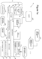
A distributed object system 10 typically includes an Object Request Broker (ORB) 11
as is symbolically illustrated in Figure 1a. ORB 11 provides all of the location and
transport mechanisms and facilities necessary to deliver a call from a client to a servant
(target object) and to return a response to the client, as will be discussed below with
reference to Figure 1b. The client and servant may be located in the same process, in
different processes on the same machine, or on completely different machines. For the
purposes of this discussion, client 20 may be any code that invokes an operation on a
distributed object and thus may or may not take the form of a distributed object or a
process. A distributed object may have a wide variety of representations. By way of
example, the distributed object may be a C++ object that has been provided by an
application developer. Alternatively, an implementation for a distributed object may be
developed within a visual application builder 15. This visual application builder allows a
developer to visually select existing object types from a catalog and graphically connect the
services provided by one object to the services needed by another (attributes, arguments,
results etc.) in order to create a new implementation for an object.
An object development facility 16 may be used to simplify the creation and the
installation of distributed objects. It is used to "wrap" or encapsulate developer objects in
distributed object code. As such, object development facility 16 may be used to transform
a developer object into an ORB object implementation 14. In this example, ORB object
implementation 14 is presented as a server as shown by its location in the diagram. A
developer uses an interface definition language to define an interface for an ORB object,
provides a developer object implementation that implements that object's behavior, and then
uses the object development facility 16 in order to produce an ORB object implementation
14. At run time, an instance of this ORB object (a servant object) is created that will utilize
this ORB object implementation 14. It should be appreciated that the object development
facility may also be used to create objects that take the role of clients at some point.
Client 20 communicates with a servant by way of a stub 21, a subcontract layer 36,
possibly a filter 40, and a transport layer 38. Stub 21 includes a surrogate 22, a method
table 24 and stub functions 25. Client 20 communicates initially with surrogate 22 that
appears to the client as the servant object. Alternatively, client 20 may communicate
directly with the servant object through a dynamic invocation interface (DII) 26 instead of
through surrogate 22, method table 24 and stub functions 25. Dynamic invocation
interface 26 is used to enable clients to construct dynamic requests. One procedure by
which a client may make a call to a servant utilizing the above layers is described in more
detail below with reference to Figure 1b.
Subcontract layer 36 provides the functionality required by an object in order to
utilize subcontracts to implement various services (or features or object mechanisms)
named by a particular subcontract, as described in greater detail in above-referenced U.S.
Patent Application Serial No. 08/554,794, filed 11/07/95. A subcontract identifies a
quality of service provided by the distributed object system that may be utilized by an
individual object. For example, a subcontract may identify that the feature of security is to
be used for a particular object. Filter 40, if being used, may perform a variety of tasks,
such as compression, encryption, tracing, or debugging, that are to be applied to
communications to and from an object.
Transport layer 38 operates to marshal, unmarshal and physically transport
information to and from a servant that typically does not share the same process as a client.
A standard implementation suite 28 (or object adapter) represents a set of
subcontracts that interact with ORB objects 14 in identical ways, as for example object key
management. One such implementation suite is described in the below description of the
present invention. It should be noted that a subcontract may belong to multiple
implementation suites. Also, implementation suites may utilize different subcontracts. A
skeleton, that may take the form of either static skeleton 32 or dynamic skeleton 30, is used
to transform requests into a format required by a servant object 78 (as will be explained in
more detail below with reference to Figure 1b). Thus, skeletons 30 and 32 call an
appropriate servant object 78. Static skeleton 32 is used to call interface-specific object
implementations 14, while dynamic skeleton 30 is used generically when interface-specific
objects are not available. An ORB interface 34 is the interface that goes directly to the ORB
that is the same for all ORBs and does not depend upon an object's interface or object
adapter.
An ORB daemon 46 is responsible for ensuring that object servers are active when
invoked by clients. A technique for starting object servers is disclosed in U.S. Patent
Application Serial No. 08/408,645 which is hereby incorporated by reference.
Secure Protocol 42 is a secure interoperability protocol that secures the internet inter-ORB
protocol and helps to transmit information through transport layer 38 in a secure
fashion. This may mean integrity protection, confidentiality, etc. The internet inter-ORB
protocol is a protocol that typically communicates between processes on different
machines. However, in some cases, the internet inter-ORB protocol may communicate
between processes on the same machine. The security server 54 is a security
administration server that secures the services that are used between processes on different
computers.
Typecode/Any module 44 implements "Typecode" and "Any" objects. Typecode
describes an Interface Definition Language (IDL) data type, allowing type descriptions to
be transmitted between clients and servers. An instance of an IDL data type may be
encapsulated by an Any object. An Any object refers to typecode of the encapsulated data,
and a generic encoding of the data.
An implementation repository 50 is used to store information relating to object
servers. Specifically, implementation repository 50 stores the information needed to start a
server process. For example, implementation repository 50 stores information such as the
location of the server program, any arguments to the program, and any environment
variables to pass to the program, etc.
Simple persistence 56 uses an Interface Definition Language (IDL)-defined type and
the output from running that IDL type through the IDL compiler, together with a portion of
additional code so that an IDL-defined type can be read from, and written to, disk. A
naming service 52 is used to name ORB objects. A client may use naming service 52 to
find a desired object by name. Naming service 52 returns an object reference, that in turn
may be used to send requests to that object. An Interface Repository 48 (IFR) knows
about all interfaces for all objects within the distributed object system.
A request made by a client using a method table ("m-table") dispatch will pass
through a variety of the aforementioned layers of the architecture on its way to the servant
as diagrammatically illustrated in Figure 1b. The request is initiated by a client and may
take any suitable form. The form of the request will depend to a large extent upon the
nature of the programming language used to create the client. By way of example, if the
client is written in the C++ language, the request may take the form of a C++ method call
62. The call is made to a designated object reference taking the form of a surrogate. The
surrogate includes methods that comply with the object's interface.
As will be appreciated by those skilled in the art, the object reference used at different
locations within a distributed object system may vary significantly in appearance. In the
embodiment described, the client side object reference is a dual pointer (referred to herein
as a "fat pointer"). A fat pointer contains two distinct pointers. A first pointer points to a
client representation ("client rep") associated with the referenced object. A second pointer
points to a method table of the method table dispatch 24 that is associated with the
referenced object. A client representation is an object that has methods that support
invocation as well as CORBA defined "pseudo" object reference operations. These
operations include, but are not limited to, a "duplicate" method, a "release" method, a
"narrow" method, a "hash" method, and an "is equivalent" method.
After the client has initiated a call, the call is processed using a method table dispatch
mechanism 24. Such a technique is disclosed in U.S. Patent Application Serial No.
08/307,929 and is hereby incorporated by reference.
The method table dispatch mechanism uses a method table that contains a list of
location indicators to stub functions 25, one of which is associated with the method to be
invoked. Stub functions 25 receive a function or procedure call in the "native" language of
the client process, then use either a subcontract layer 36 or a native call to eventually call the
corresponding servant object. The native language may be any suitable language, as for
example a language such as C++.
Method table dispatch 24 determines the appropriate one of the stub functions 25 to
process the method call, and then pairs the method call with the appropriate stub function.
In the event that the client making the method call is in the same process as the servant
object, a local stub function is called. The local stub function sends the method call directly
to servant object 78. Alternatively, if the servant object is in a different process, i.e. a
remote process, a remote stub function is called. The remote stub function invokes the
client representation, that delivers the invocation to servant object 78.
Subcontracts implemented by subcontract layer 36 are logic modules that provide
control of the basic mechanisms of object invocation and argument passing that are
important in distributed object systems. A subcontract implemented by subcontract layer
36 determines a specific quality of service for use by an object. A subcontract is uniquely
identified by a subcontract identifier that is typically embedded in an object reference. A
quality of service is a set of service properties. Among possible service properties that are
selectable are qualities relating to server activation, security, transactions, filterability, and
clean shut-down. Subcontracts are configured such that certain qualities of service are
available. With predetermined qualities of service, the overhead associated with processing
individual service properties is reduced. Realistically, only "reasonable" or commonly
used combinations of service properties are supported with subcontracts. However,
subcontracts may be created to meet the specific requirements of a given distributed object
system.
The identification of an appropriate subcontract in subcontract layer 36 may be
thought of as the identification of a desired function that is unique to that subcontract. For
example, a marshal function or an unmarshal function is defined for each subcontract. A
subcontract marshal function is used by a stub to marshal an object reference so that it may
be transmitted to another address space, or domain. The object reference is typically
processed by a transport mechanism in transport layer 38.
A transport mechanism such as T1, T2, etc., that is a part of the transport layer 38
is used to marshal and physically transport information to and from servant objects.
Information, i.e. the object reference or the request, is converted into protocols appropriate
to a given domain. By way of example, protocols may include, but are not limited to,
Ethernet protocols and general inter-ORB protocols (GIOPs). In some uncommon cases,
protocols may even entail the use of electronic mail to transmit instructions to be
implemented on a server. After information is marshaled, the transport mechanism then
transports information through any combination of an operating system, a device driver, or
a network, that are all a part of hardware 70 used by the client side of a distributed object
system.
While transport mechanisms require a conversion of information into a protocol
appropriate to a given domain, some transport mechanisms do not require the encoding of
information for different domains. One transport mechanism that does not require a
conversion of information into a protocol appropriate to a domain other than the one on
which information originates is termed a "door". Doors are essentially gateways between
two different processes on the same host. The use of doors eliminates the need for a
conversion of information into a canonical implementation in transport layer 38, as there is
no need to encode information into a protocol that may be used by a different machine by
virtue of the fact that information is remaining on the same host and therefore does not
require a change of domain. Hence, information may simply be "flattened out," or
marshaled into a stream that is not encoded for use by a different machine, and passed
between the two processes on the host.
Once information is transported through hardware 70 used by the client side, the
information is then transported to hardware 70 on the server side of a distributed object
system. Once information is routed through hardware 70, the server side of a distributed
object system invokes a transport mechanism such as T1, T2 etc. to receive information on
an end point that is a part of transport layer 38. In the event that an end point is not created
by transport layer 38, transport layer 38 provides the functionality needed for the end point
to be created by subcontract layer 36. By way of example, a dedicated end point is
typically created by subcontract layer 36, while cluster end points, which typically include
network and TCP/IP end points, are typically created by transport layer 38. Regardless of
whether end points are created by subcontract layer 36 or transport layer 38, end points
"live in," i.e. are a part of, transport layer 38. End points are essentially ports that receive
information from a different domain. After an end point in transport layer 38 receives
information transported from a different domain, the end point then dispatches the
information from transport layer 38 to subcontract layer 36. Subcontract layer 36 then
dispatches the information to the skeleton and the servant.
Subcontract layer 36 provides the functionality to unmarshal at least some of the
information it has received. That is, subcontract layer 36 unmarshals at least part of the
request. Then, the request is dispatched to a skeleton 31 that transforms the request into an
implementation specific format required by servant object 78. The skeleton 31 may either
be a static skeleton 32 or a dynamic skeleton 30 as described above.
In general, a remote request is routed through the client side and the server side as
described above. The method call 62 is received, method table dispatch layer 24 is used to
identify an appropriate subcontract prior to the selection of a transport mechanism in
transport layer 38 that marshals the request and prepares it for transport to another domain.
Through hardware 70, the marshaled request is transported to the server side where it is
received on an end point that is a part of transport layer 38. An appropriate end point
receives information transported across a wire, and information is dispatched from
transport layer 38 to subcontract layer 36, that provides the functionality to at least partially
unmarshal the information it has received. The subcontract layer then dispatches the
request to skeleton 31 that transforms the request into a specific format required by servant
object 78. This path is shown by arrow 77, and is the path that may be taken by both
remote and local requests.
However, if a client and a server are in a local process, i.e. both the client and the
server are in the same process, the use of the path shown by arrow 77 as described above
is unnecessarily complex. If it is known that the client and the server are in the same
process, it is possible to shorten the invocation path, or flow path of a request for service.
If a local process may be identified when an object reference is created, shortened flow
paths, i.e. the paths represented by arrows 75 and 76, may be taken to send a request from
a client to a server that are on the same host. The path represented by arrow 76 is more
likely to be taken, as it uses subcontract layer 36 to identify an appropriate subcontract.
However, in situations in which an appropriate subcontract does not need to be explicitly
identified, the path represented by arrow 75 may be taken.
Figure 5 will now be used to describe an embodiment of an object reference. As will
be familiar to those skilled in the art, object references may take a variety of forms
depending upon the location within the process that they are being held at any given time.
However, by way of background, a representative object reference for use in a system that
utilizes a low overhead implementation suite is illustrated in Figure 5. In the
implementation shown therein, object reference 150 includes a host identifier 152, a port
designation 154, and an object key 156. Object key 156 includes a subcontract identifier
158, a server identifier 160, an implementation identifier 162, and a user key 164. Host
identifier 152 denotes a particular computer in a network, while port designation 154
identifies the port of the selected computer that is to be used for communication. Object
key 156 provides further identifying information used in order to locate a desired servant
object on its host machine.
Server identifier 160 names a particular process or program in which the servant
object resides, while user key 164 is a unique number or string used to locate the servant
within the process named by server identifier 160. Subcontract identifier 158 is used to
attach the protocol of a particular subcontract and its associated services with a servant, and
implementation identifier 162 names an implementation of an interface that is to be used
with that servant object.
DESCRIPTION OF THE PREFERED EMBODIMENTS
The present invention relates to an object adaptor that is able to interact with and make
use of a subset of all available features within a distributed object system through the use
of subcontracts. Such an object adaptor need not necessarily supply an exhaustive fixed set
of all features for all objects; to the contrary, such an object adaptor is designed to supply a
smaller subset of features, resulting in a lower overhead for the CPU, quicker response,
etc.
This low-overhead (or "light-weight") object adaptor provides various functionalities
for use with objects in the context of subcontracts. By way of example, these
functionalities include implementation activation, object reference creation and object
invocation. The creation of object references and implementation activation in accordance
with one embodiment of one aspect of the present invention will be described below with
reference to Figures 6 through 11. The functionality relating to object invocation is
discussed below with reference to an embodiment illustrated in Figures 12a, 12b and 13.
In another aspect of the invention specialized data structures are provided that are arranged
to facilitate efficient implementation of these functionalities.
As discussed above, the distributed object system may provide various features such
as security or server activation for use by individual objects. These features are grouped
into sets, and each set of one or more features is termed a subcontract. Each subcontract in
turn is identified by a Subcontract Identifier, that may be a number or any other suitable
identifier. For example, as illustrated in Figure 2, Subcontract 1 may indicate that a clean
shutdown should not be provided, that an authentication protocol such as MD5 should be
used, that objects should have persistence and that server activation should be turned on.
Thus, Subcontract 1 identifies four features available for an object, and whether these
features are present (or turned on or off), are further qualified or have a specific value. A
set of features is referred to herein as "a quality of service." Thus, each Subcontract
Identifier identifies a specific quality of service. In the embodiment shown, the features
that define a specific quality of service are identified in a list of name-value pairs.
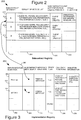
Referring next to Figure 2, a subcontract registry data structure 200 in accordance
with one embodiment of the present invention will be described. The subcontract registry
is used to store the information that associates a particular quality of service with a unique
Subcontract Identifier and with its associated subcontract client representation create
function. This table 200 is termed a subcontract registry in that it registers and makes
available for searching all of the available subcontracts within the system. In this fashion,
the table is advantageous in that it allows any number of implementations to be associated
with a particular subcontract, as will be discussed below with reference to Figure 3. It
should be appreciated that although a predetermined number of permutations of features
within a system are possible, the subcontract registry may only identify a subset of these
possible subcontracts that have been implemented within the distributed object system.
This table 200 may be implemented as a hash table, linked list or any other suitable data
structure.
The subcontract registry 200 includes a Subcontract Identifier column 202, an
associated quality of service list column 204, a subcontract client representation create
function column 206, and location indicators to other functions 208. Each row of the table
210 is termed a Subcontract Meta Object and, by way of example, may be implemented as a
C++ object. In the embodiment shown, a plurality of Subcontract Meta Objects 212, 214
and 216 are provided in the subcontract registry 200. The first Subcontract Meta Object
212 has a Subcontract Identifier of "1" and is thus identified as Subcontract 1.
Subcontract 1 lists the following features for its quality of service: clean shutdown,
security, persistence and server activation. The name-value pairs in this quality of service
list indicates that a clean shutdown will not be implemented, that for security, an
authentication protocol using MD5 will be used, that persistence is turned on and that
server activation is present. In column 206, Subcontract 1 has a location indicator to its
associated subcontract client representation create function, Client Rep Create1. Column
208 includes a plurality of location indicators to various other functions associated with this
Subcontract Meta Object such as location indicators to an unmarshal function, a destringify
function and a bad server identifier handler.
Each name-value pair contains a name that indicates a particular feature of the system,
and a value for that name indicating whether the feature is present or not or which aspect of
the feature is to be used. For example, for the feature of transactions, its value may either
be YES or NO, indicating whether this feature is turned on or off. However, for the
security feature, its value may be a specific aspect of security such as authentication
followed by a particular protocol to use such as MD5, Kerberos, or SPKM. The name
field may be represented by a string variable, and the value field may also be a string or a
number. Thus, a specific quality of service chosen by a developer for use with an object or
objects within an application indicates the features that the developer wishes to take
advantage of. Because these features may be unique to each object, it is necessary to have
a specific create function for each quality of service that will create an object location
indicator to the particular object being referenced.
The second illustrated Subcontract Meta Object 214 is the Subcontract Meta Object
for Subcontract 2. The quality of service list for this subcontract indicates that a clean
shutdown will be implemented, that for security, an authentication protocol using MD5 will
be used, that persistence is turned on and that server activation is present. The Subcontract
Meta Object 216 indicates that for Subcontract 3 it will allow clean shutdowns, that for
security, an authentication protocol using MD5 will be used, that persistence is present and
that server activation will also be turned on.
The subcontract registry 200 will typically have a group of associated functions that
are used to organize and access the registry. By way of example, the associated functions
may include an Add function, a Find function, a Get First function and a Get Next
function. The Add function may be used to add a new quality of service to the table. In the
described embodiment, the Add function takes as arguments a Subcontract Identifier and a
Subcontract Meta Object. A Find function takes as an argument a Subcontract Identifier
and returns the Subcontract Meta Object associated with that identifier. The functions Get
First and Get Next return the appropriate Subcontract Meta Object and are used to iterate
over the entire table and thus search it completely for a particular quality of service. This
subcontract registry may be used in the following manner. When a client wishes to make a
call to a particular server object, the subcontract registry may be used to look up the
Subcontract Identifier associated with that server object and then to call the appropriate
subcontract client representation create function in order to create an object reference to the
particular server object using the appropriate features.
Each object in the system is associated with an implementation definition. Each
implementation definition for an object includes such information as the name of the
implementation, which subcontract to use in creating the object, the Interface Identifier for
the object , a set of call back functions and skeleton information. These call back functions
may be stored in an object. Such information for an implementation definition may be
stored in a wide variety of manners. By way of example, such information may be stored
in an implementation registry table.
Figure 3 shows an implementation registry 250 in accordance with one embodiment
of the present invention. The implementation registry has entries corresponding to various
implementation definitions. Through the use of this table, an implementer of an object
server will be able to provide multiple, different implementations of a single ORB object
type in the same object server. That is, one object type may hake various implementations
that are identified by distinct Implementation Identifiers. Each implementation defines the
behavior for all of the operations and attributes of the interface that it supports. In other
words, each interface may have many implementations. Therefore, each Implementation
Identifier represents a distinct implementation for an object that uses a particular
subcontract. And each implementation may use a different subcontract by way of a
subcontract location indicator in the implementation registry as will be discussed below. In
this fashion, the implementation registry is advantageous in that it allows an invoking
function to choose a particular implementation which in turn may use a desired subcontract
of the subcontract registry.
Each implementation definition represents an entry in the implementation registry that
contain location indicators to the different data stored. The implementation registry 250
includes an Implementation Identifier column 252 that names the implementation, a
Subcontract Meta Object column 254, an Interface Identifier column 256, a column 257 for
a Ready Flag, a call back functions column 258, and a skeleton information column 259.
The Implementation Identifier is a name for the implementation that is supplied by the
developer when an implementation definition is created. The Subcontract Meta Object is a
location indicator from a particular implementation definition to a Subcontract Meta Object
contained in the subcontract registry 200. The Interface Identifier is a fixed globally unique
name of the type of a particular interface. The Ready Flag will be set for a particular
implementation definition when the implementation has been prepared as will be described
below with reference to Figure 8. If the Ready Flag is not set, then the dispatch function
may have to wait temporarily until the implementation is ready, as described below with
reference to Figures 12a and 12b, and specifically in step 727 of Figure 12b. The skeleton
information provides information and functions for use by the skeleton associated with this
implementation. The call back functions are a set of functions associated with each
implementation. A wide variety of call back functions may be associated with a particular
implementation. By way of example, the call back functions Lookup, Post Invoke,
Revoke, Deactivate and Shutdown will be illustrated.
The Lookup function takes as an argument a User Key and returns a location
indicator to a servant, which may be NULL if no corresponding object exists. If the object
is found the invocation continues. If not, an exception is returned to the client. The User
Key is reference data supplied by the developer and may be any arbitrary data. The User
Key forms part of the object reference as will be explained below with reference to Figure
5. The Post Invoke function takes as an argument a user key and returns no value. It may
execute various operations that the developer wishes to perform after the invocation of an
object. The Revoke function takes as an argument the User Key and performs the function
of preventing an object from being referred to. The Deactivate function takes as arguments
the User Key and a deactivate closure. The deactivate closure is a procedure that enables
the ORB to do some internal clean up once the object has been deactivated by the body of
the deactivate function. Essentially, the deactivate function itself serves to make the object
inaccessible. The Shutdown function is used to shutdown a particular implementation
definition by removing all servant objects if necessary. Each set of call back functions 258
associated with an implementation definition may be represented in an object that contains
these functions.
Referring again to Figure 3, shown in particular in the implementation registry 250 is
an implementation definition 262. This definition is for a PRINTER implementation of the
interface PRINTER INTERFACE and it has a location indicator 266 to Subcontract 1 of the
subcontract registry. It also has five unique call back functions, and a unique skeleton
dispatch function. Also shown is an implementation definition 264 for a MODEM
implementation that has a location indicator to its corresponding subcontract, and that
implements the interface identified by MODEM INTERFACE.
Associated with this implementation registry 250 are various functions used to
organize and access the registry. By way of example, the function Add may be used to add
an implementation definition with a particular Implementation Identifier to the
implementation registry. The function Find may take as an argument an Implementation
Identifier and will search through the registry in order to return the corresponding
implementation definition.
Figure 4 at 300 shows how the subcontract registry 200 and the implementation
registry 250 interact with one another. The subcontract registry 200 registers various
subcontracts by having Subcontract Meta Object entries such as 212, 214 and 216, etc.
Each of these Subcontract Meta Objects identifies a unique set of features of the system.
For example, Subcontract Meta Object 1 identifies Subcontract 1 that identifies the features
security 302, persistence 304 and clean shutdown 306. Similarly, Subcontract 2 identifies
the feature server activation 308. Subcontract 3 identifies the features clean shutdown 306,
server activation 308 and transactions 310.
The interaction between the two takes place as follows. The implementation registry
250 identifies various implementation definitions such as PRINTER 262 and MODEM
264. Each of these implementation definitions references a single one of the Subcontract
Meta Objects through, for example, link 266. It may be possible for a particular
Subcontract Meta Object to be referenced by more than one implementation definition. For
example, both the PRINTER and the MODEM definitions reference Subcontract 1 through
Subcontract Meta Object 1.
Figure 5 at 150 shows the object reference described above in the overview. It
should also be noted that the subcontract Identifier 158 identifies not only which
subcontract the object will utilize but also identifies a particular Subcontract Meta Object in
the subcontract registry through column 202 of Figure 2. The Implementation Identifier
162 identifies the name of the implementation for this object and also indicates an
implementation definition by way of column 252 of the implementation registry of Figure
3.
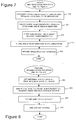
Figure 6 shows a procedure 400 that describes the typical steps needed to create
objects for which a server may dispatch requests. The steps of creating an implementation
definition and preparing it typically occur when the server process is initialized. Object
references are created in the server and given to the client in response to requests on other
objects which are usually referred to as factory objects. Factory objects are usually well-known
objects that are created when a server is installed, or else when it initializes. These
well-known objects are typically registered with a naming service so that clients can find
them. Thus, there are preferably two cases in which step 406 below is called: as part of
the server installation or initialization, or in an operation on a factory object implemented in
the server. An implementation definition is created by filling out a row of the
implementation registry, that will then be accessed by an invocation. Once ready, this
implementation may receive invocations upon its objects. If the implementation is no
longer able to receive invocations, it may be deactivated, as discussed below with reference
to Figure 10, or the ORB may wish to shutdown as discussed below with reference to
Figure 11.
In a first step 402 of Figure 6 the create implementation definition function is called.
This function will take as arguments a desired quality of service list, a name for an
implementation and skeleton information, and will return an implementation definition.
This step will be explained in more detail below with reference to Figure 7. In step 404 a
prepare implementation definition function is called. This function takes as arguments an
implementation definition and a set of call back functions for that implementation definition
in order to install these functions in the implementation definition. It will be explained in
more detail below with reference to Figure 8. Once the implementation is ready, instep
406 a create object reference function is called. This function takes as arguments an
implementation definition and the User Key and returns an object reference. This create
object reference function produces an object reference to a servant that may or may not exist
according to the subcontract specified. This step will be explained in more detail below
with reference to Figure 9.
Once an object has been created by producing its object reference the object is
available for use. At this point the client may make use of the server object and other
processing may occur. Thus step 408 indicates a wait state in which the system continues
processing of an application until the occurrence of two possible situations. These
situations are described in steps 410 and 414. Step 410 checks whether any more
invocations for this particular implementation are desired. In other words, if the developer
no longer has any use for this object it will be removed in step 412. Otherwise, the system
continues processing and uses this implementation. In step 412 the deactivate
implementation function is called. This function takes as an argument an implementation
definition and removes that implementation. The deactivate implementation function will be
explained in more detail below with reference to Figure 10.
Occasionally, the object request broker (ORB) may wish to shut down the server. If
not, then the system continues processing as in step 408. However, if the system is to be
shut down then in step 416 the server shutdown function is called. This server shutdown
function will be explained in more detail below with reference to Figure 11.
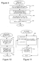
Referring next to Figure 7, a create implementation definition function suitable for
implementing step 402 in Figure 6 will be described in more detail. The create
implementation definition function takes as arguments a quality of service list, a name for
an implementation and an Interface Identifier. In step 452 the desired quality of service list
is used to search through the subcontract registry and match the quality of service list of an
existing Subcontract Meta Object. This step may be performed by searching each entry in
the subcontract registry using the subcontract registry functions as discussed above. In
step 454 an entry is created in the implementation registry using the Interface Identifier and
the name for the implementation as the Implementation Identifier. In step 456 the
Subcontract Meta Object field for this new entry is updated to point to the identified
Subcontract Meta Object found in step 452. Next, in step 457 all skeleton information is
stored in this new entry, including the skeleton dispatch function unique for this
implementation definition. After this step this new implementation definition is returned
and this function is done and control returns to step 404 of Figure 6.
Referring next to Figure 8, a prepare implementation definition function suitable for
implementing step 404 in Figure 6 will be described in more detail. This function takes as
arguments an implementation definition and a set of associated call back functions. In step
484 the implementation definition is used to determine the corresponding Implementation
Identifier. Next, in step 486 these call back functions are inserted in the implementation
registry at the entry corresponding to the found Implementation Identifier. In step 488 the
implementation Ready Flag is set to YES to indicate that this implementation is now ready
for use. Because the implementation is now ready, in step 490 any waiting procedures are
now unblocked and may use this implementation. For example, step 727 of the invocation
procedure of Figure 12b must wait until the implementation is ready. After this step 490
the function is done and control returns to step 406 of Figure 6.
Referring next to Figure 9, a create object reference function suitable for
implementing step 406 in Figure 6 will be described in more detail. This function takes as
arguments an implementation definition and a User Key. It will eventually create and
return an object reference by using the subcontract client representation create function
described below. In step 502 the implementation definition is used to reference its
corresponding entry in the implementation registry in order to produce the corresponding
Subcontract Meta Object location indicator that points to the appropriate Subcontract Meta
Object in the subcontract registry. In step 504 the subcontract client representation create
function corresponding to the entry in the table for this found Subcontract Meta Object is
returned. In step 506 this subcontract client representation create function is called with the
User Key and the received implementation definition as arguments. This client
representation create function creates an object reference for a servant (that may or may not
yet exist) corresponding to the Interface Identifier and named Implementation Identifier of
the received implementation definition. Because this client representation create function is
unique to each subcontract, this step utilizes the appropriate features of the corresponding
subcontract in order to return the object reference. In step 508 this object reference created
is returned and the function is done and control returns to step 408 of Figure 6.
Referring next to Figure 10, a deactivate implementation function suitable for
implementing step 412 in Figure 6 will be described in more detail. This function take as
an argument an implementation definition. In step 520 the implementation definition is
used to produce the corresponding Implementation Identifier. In step 522 the entry in the
implementation registry corresponding to this Implementation Identifier is removed. This
removal effectively prevents this implementation of an interface from being used because
the implementation is no longer present in the implementation registry. After this step the
function is done and control returns to the end of Figure 6.
Referring next to Figure 11, a shut down function suitable for implementing step
416 in Figure 6 will be described in more detail. This shutdown function is used to
shutdown all implementation of objects within the ORB. Step 540 introduces a looping
structure that will step through all entries in the implementation registry. An index J is first
set equal to the first entry in the implementation registry. Upon each iteration of this loop,
the index J will be set to the next entry in the table. Step 540 also tests whether the last
entry has been processed, if so, then this function is done. In step 542 the shutdown call
back function corresponding to a particular implementation definition at entry J is called in
order to shutdown this particular implementation. Once all implementations have been
shutdown, then the ORB may safely cease processing. After this step the function is done
and control returns to the end of Figure 6. Now that an embodiment of the create object
reference function of Figure 6 has been described, the dispatch function will be described.
Figures 12a, 12b and 13 illustrate an embodiment of a procedure for performing
object invocation. This procedure makes use of the implementation and subcontract
registries in order to take advantage of subcontracts in accordance with one of the goals of
the present invention. Object invocation is the process by which a client invokes an
operation or accesses an attribute of a server object, a call is made through the ORB to the
server object, the operation is invoked upon the server object, and a result is returned to the
client (if required). Once the mechanisms on the client side have processed this request and
passed the request to the client transport layer, the client transport layer sends the request to
the server's transport layer. Figures 12a, 12b and 13 describe how the transport layer calls
a particular dispatch function of a subcontract in order to invoke the server object. Each
subcontract has a unique dispatch function that performs the steps that will be described
below. The procedure will use the implementation registry in order to find the appropriate
lookup function and the appropriate skeleton dispatch function for that implementation.
The subcontract registry will also be used to provide a bad server identifier handler function
corresponding to a particular subcontract if necessary.
Figure 12a begins by having the transport layer call the dispatch function for a
particular subcontract using the subcontract identifier. Due to the client's invocation on the
object reference, the transport layer has been provided with a marshal buffer that contains
among other information, the object key for the server object. This object key contains
information as shown in Figure 5. The marshal buffer also contains the name of the
method to be invoked upon the server object and any necessary arguments. As the
subcontract identifier is contained within the object key as shown in Figure 5, the transport
layer is able to "peek" at this subcontract identifier in order to determine which subcontract
is appropriate and which dispatch function should be called.
In step 702 this subcontract identifier is extracted from the object reference in the
marshal buffer. The process of extraction means that this information is taken from the
marshal buffer and is no longer present in the marshal buffer. Next, in step 704 this
extracted subcontract identifier is compared with the current subcontract that is being
utilized in order to verify that the appropriate subcontract is being used. As described
above, during object development, an application developer has associated a particular
subcontract with an object by using a subcontract identifier.
In step 706 the server identifier is extracted from the object reference in the marshal
buffer. The server object that is the subject of the invocation is present within a particular
server process on a host computer; thus, it is important to verify that this server identifier
matches with the identifier of the current server. In step 708 this extracted server identifier
is compared with the identifier of the current server in order to determine if the object
reference is referencing the appropriate server process. Step 710 determines if the extracted
server identifier is valid and does match with the current server. If not, this indicates that
the server identifier is invalid and appropriate action should be taken. This action may be
performed by a bad server identifier handler function. Step 712 determines if an
appropriate bad server identifier handler is registered in the subcontract meta object.
Because the subcontract identifier has already been extracted from the object reference, this
step may be performed by using the subcontract registry of Figure 2. The subcontract
identifier acts as a key to a particular row of this table that allows a search of column 208 in
order to determine if the bad server identifier handler is present. If the handler is not
present, then the system throws an exception relating to this situation in step 716 and the
dispatch function ends. If, however, the handler is registered in the subcontract meta
object, then in step 714 this bad server identifier handler is called with the subcontract
identifier and the marshal buffer as arguments. After this step, the dispatch function ends.
Returning now to step 710, if the extracted server identifier does match with the
current server, then control moves to step 718. In step 718 the implementation identifier is
extracted from the object reference in the marshal buffer. In step 720 this extracted
implementation identifier is used as a key to the implementation registry of Figure 3 in
order to find the appropriate implementation definition. The use of the implementation
registry is explained above with reference to Figure 3. This step 720 may be performed by
searching through column 252 of the implementation registry of Figure 3 in order to
determine if the implementation identifier is present in the table. If in step 722 it is
determined that the implementation definition is not found then in step 724 an exception is
thrown relating to this condition and the dispatch function ends. If however, the
implementation definition is found then the operation may proceed with use of the
definition.
However, even if an implementation definition is found, it may not necessarily be
ready for use. An implementation definition is ready, or prepared, if the prepare
implementation definition step 404 of Figure 6 has been executed. Once this step has been
executed, the Ready Flag will be set. Step 726 tests whether this Ready Flag has been set.
If not, then in step 727 the dispatch function enters a wait state in which it waits for the
implementation definition to become ready. Once the implementation definition is ready
then control moves from step 726 to step 728. In step 728 the lookup function from the
implementation definition is extracted. This lookup function is one of the call back
functions of column 258 of Figure 3 and will be used to produce a local location indicator
to the servant. In step 730 the User Key is extracted from the object reference in the
marshal buffer. Next, in step 732 the lookup function is called with the User Key as an
argument. Once this function has executed it will return a location indicator to the servant.
This location indicator may be implemented in the local language of the server. By way of
example, this location indicator may be a C++ object pointer that references the servant
C++ object.
Now that a local location indicator has been obtained to the servant object the dispatch
function is ready to execute the appropriate method upon the servant object that was
originally requested by the client. In step 733 the method descriptor is extracted from the
marshal buffer. The method descriptor is a representation from the client's point of view of
that particular method name defined upon the servant that the client wishes to invoke. In
step 734 the skeleton dispatch function is extracted from the implementation definition.
This skeleton dispatch function may be found in the implementation registry in column 259
of Figure 3. In step 736 this skeleton dispatch function is called with the arguments
servant location indicator, marshal buffer and the method descriptor. This function will be
explained in more detail below with reference to Figure 13. The skeleton dispatch function
achieves the result of executing the method upon the servant that the client requested be
performed. Once this operation has taken place the invocation of the server object by the
client has finished. However, an additional function may be executed. The post invoke
function is a developer defined function for each implementation that achieves a
functionality that the developer wishes. In step 738 this post invoke function is extracted
from the implementation definition. In step 740 this post invoke function is called with the
User Key as an argument. The post invoke function may be used by the developer to
perform a particular action after the invocation of an object. For example, Lookup/ Post-Invoke
may count the number of active invocations on a particular server. This is useful
for managing the life cycle of servant objects.
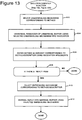
Referring next to Figure 13, a skeleton dispatch function suitable for implementing
step 736 in Figure 12b will be described in more detail. This function first begins in step
802 in which an unmarshaling mechanism is selected based upon the method descriptor.
The unmarshaling mechanism may be a sequence of code that is selected by a switch
statement for example. As other information has already been extracted from the marshal
buffer, the only information remaining in the marshal buffer at this point are the arguments
of the method to be called. In step 804 the selected unmarshaling mechanism is used to
unmarshal the remainder of the marshal buffer into the invocation arguments. In step 806
the method descriptor is used to invoke the method defined upon the servant using the
invocation arguments. This step has the effect of executing the method that was originally
requested by the client. It is possible that this method returns no value at all and performs
other functions, or may be that the method returns a value to the client. Step 808
determines if the method produces a reply. If not, then this function is done. If so, then
control moves to step 810. In step 810 an appropriate marshalling mechanism is selected
corresponding to the method descriptor. In step 812 the selected marshalling mechanism is
used to marshal the reply into the marshal buffer. At this point the marshal buffer is ready
to be returned through the transport layer to the client. After this step, this function is done
and control returns to step 738 of Figure 12b.
The present invention as described above employs various process steps involving
data stored in computer systems. These steps are those requiring physical manipulation of
physical quantities. Usually, though not necessarily, these quantities take the form of
electrical or magnetic signals capable of being stored, transferred, combined, compared,
and otherwise manipulated. It is sometimes convenient, principally for reasons of common
usage, to refer to these signals as bits, values, elements, variables, characters, data
structures, or the like. It should be remembered, however, that all of these and similar
terms are to be associated with the appropriate physical quantities and are merely
convenient labels applied to these quantities.
Further, the manipulations performed are often referred to in terms such as
identifying, running, or comparing. In any of the operations described herein that form part
of the present invention these operations are machine operations. Useful machines for
performing the operations of the present invention include general purpose digital
computers or other similar devices. In all cases, there should be borne in mind the
distinction between the method of operations in operating a computer and the method of
computation itself. The present invention relates to method steps for operating a computer
in processing electrical or other physical signals to generate other desired physical signals.
The present invention also relates to an apparatus for performing these operations.
This apparatus may be specially constructed for the required purposes, or it may be a
general purpose computer selectively activated or reconfigured by a computer program
stored in the computer. The processes presented herein are not inherently related to any
particular computer or other apparatus. In particular, various general purpose machines
may be used with programs written in accordance with the teachings herein, or it may be
more convenient to construct a more specialized apparatus to perform the required method
steps. The required structure for a variety of these machines will appear from the
description given above.
In addition, the present invention further relates to computer readable media that
include program instructions for performing various computer-implemented operations.
The media and program instructions may be those specially designed and constructed for
the purposes of the present invention, or they may be of the kind well known and available
to those having skill in the computer software arts. Examples of computer readable media
include, but are not limited to, magnetic media such as hard disks, floppy disks, and
magnetic tape; optical media such as CD-ROM disks; magneto-optical media such as
floptical disks; and hardware devices that are specially configured to store and perform
program instructions, such as read-only memory devices (ROM) and random access
memory (RAM). Examples of program instructions include both machine code, such as
produced by a compiler, and files containing higher level code that may be executed by the
computer using an interpreter.
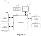
Figure 14 illustrates a typical computer system in accordance with an embodiment of
the present invention. The computer system 100 includes any number of processors 102
(also referred to as central processing units, or CPUs) that are coupled to storage devices
including primary storage 106 (typically a random access memory, or RAM), primary
storage 104 (typically a read only memory, or ROM). As is well known in the art, primary
storage 104 acts to transfer data and instructions uni-directionally to the CPU and primary
storage 106 is used typically to transfer data and instructions in a bi-directional manner.
Both of these primary storage devices may include any suitable of the computer-readable
media described above. A mass storage device 108 is also coupled bi-directionally to CPU
102 and provides additional data storage capacity and may include any of the computer-readable
media described above. The mass storage device 108 may be used to store
programs, data and the like and is typically a secondary storage medium such as a hard disk
that is slower than primary storage. It will be appreciated that the information retained
within the mass storage device 108, may, in appropriate cases, be incorporated in standard
fashion as part of primary storage 106 as virtual memory. A specific mass storage device
such as a CD-ROM 114 may also pass data uni-directionally to the CPU.
CPU 102 is also coupled to an interface 110 that includes one or more input/output
devices such as such as video monitors, track balls, mice, keyboards, microphones, touch-sensitive
displays, transducer card readers, magnetic or paper tape readers, tablets,
styluses, voice or handwriting recognizers, or other well-known input devices such as, of
course, other computers. Finally, CPU 102 optionally may be coupled to a computer or
telecommunications network using a network connection as shown generally at 112. With
such a network connection, it is contemplated that the CPU might receive information from
the network, or might output information to the network in the course of performing the
above-described method steps. The above-described devices and materials will be familiar
to those of skill in the computer hardware and software arts.
Although the foregoing invention has been described in some detail for purposes of
clarity of understanding, it will be apparent that certain changes and modifications may be
practiced within the scope of the appended claims. For instance, the present invention may
be practiced within any suitable distributed object environment. And the subcontract
registry and implementation registry tables may be represented in different forms or may
even be combined into one data structure while still accomplishing the goals of the present
invention. Also, although the create object reference and object invocation flow charts
describe one set of functions that utilize the notion of a subcontract within the described
low overhead object adaptor, it is contemplated that other similar functions may use
subcontracts through a form of the subcontract registry and implementation registry tables
as described above. Therefore, the described embodiments should be taken as illustrative
and not restrictive, and the invention should not be limited to the details given herein but
should be defined by the following claims and their full scope of equivalents.