EP0819441A1 - Syringe with cap - Google Patents
Syringe with cap Download PDFInfo
- Publication number
- EP0819441A1 EP0819441A1 EP96111645A EP96111645A EP0819441A1 EP 0819441 A1 EP0819441 A1 EP 0819441A1 EP 96111645 A EP96111645 A EP 96111645A EP 96111645 A EP96111645 A EP 96111645A EP 0819441 A1 EP0819441 A1 EP 0819441A1
- Authority
- EP
- European Patent Office
- Prior art keywords
- cap
- main body
- needle
- cap main
- syringe
- Prior art date
- Legal status (The legal status is an assumption and is not a legal conclusion. Google has not performed a legal analysis and makes no representation as to the accuracy of the status listed.)
- Withdrawn
Links
Images


Classifications
-
- A—HUMAN NECESSITIES
- A61—MEDICAL OR VETERINARY SCIENCE; HYGIENE
- A61M—DEVICES FOR INTRODUCING MEDIA INTO, OR ONTO, THE BODY; DEVICES FOR TRANSDUCING BODY MEDIA OR FOR TAKING MEDIA FROM THE BODY; DEVICES FOR PRODUCING OR ENDING SLEEP OR STUPOR
- A61M5/00—Devices for bringing media into the body in a subcutaneous, intra-vascular or intramuscular way; Accessories therefor, e.g. filling or cleaning devices, arm-rests
- A61M5/178—Syringes
- A61M5/31—Details
- A61M5/32—Needles; Details of needles pertaining to their connection with syringe or hub; Accessories for bringing the needle into, or holding the needle on, the body; Devices for protection of needles
- A61M5/3205—Apparatus for removing or disposing of used needles or syringes, e.g. containers; Means for protection against accidental injuries from used needles
- A61M5/321—Means for protection against accidental injuries by used needles
- A61M5/3216—Caps placed transversally onto the needle, e.g. pivotally attached to the needle base
-
- A—HUMAN NECESSITIES
- A61—MEDICAL OR VETERINARY SCIENCE; HYGIENE
- A61M—DEVICES FOR INTRODUCING MEDIA INTO, OR ONTO, THE BODY; DEVICES FOR TRANSDUCING BODY MEDIA OR FOR TAKING MEDIA FROM THE BODY; DEVICES FOR PRODUCING OR ENDING SLEEP OR STUPOR
- A61M2205/00—General characteristics of the apparatus
- A61M2205/58—Means for facilitating use, e.g. by people with impaired vision
- A61M2205/583—Means for facilitating use, e.g. by people with impaired vision by visual feedback
-
- A—HUMAN NECESSITIES
- A61—MEDICAL OR VETERINARY SCIENCE; HYGIENE
- A61M—DEVICES FOR INTRODUCING MEDIA INTO, OR ONTO, THE BODY; DEVICES FOR TRANSDUCING BODY MEDIA OR FOR TAKING MEDIA FROM THE BODY; DEVICES FOR PRODUCING OR ENDING SLEEP OR STUPOR
- A61M5/00—Devices for bringing media into the body in a subcutaneous, intra-vascular or intramuscular way; Accessories therefor, e.g. filling or cleaning devices, arm-rests
- A61M5/50—Devices for bringing media into the body in a subcutaneous, intra-vascular or intramuscular way; Accessories therefor, e.g. filling or cleaning devices, arm-rests having means for preventing re-use, or for indicating if defective, used, tampered with or unsterile
- A61M5/5086—Devices for bringing media into the body in a subcutaneous, intra-vascular or intramuscular way; Accessories therefor, e.g. filling or cleaning devices, arm-rests having means for preventing re-use, or for indicating if defective, used, tampered with or unsterile for indicating if defective, used, tampered with or unsterile
Definitions
- the present invention relates to a syringe with a cap, and more specifically, to a syringe with a cap capable of securely locking the cap at an open position and a closed position.
- a syringe including a syringe main body having a needle mounted at the extreme end thereof and a cap for covering the needle of the syringe main body as this type of the syringe (for example, Japanese Utility Model Application Laid-Open No. Sho 63-189255, Japanese Utility Model Application Laid-Open No. Sho 64-17248, Japanese Utility Model Application Laid-Open No. Hei 1-62849 and the like).
- the aforesaid conventional cap includes a cap securing portion secured at the extreme end of the syringe main body and a cap main body pivotally coupled with the cap securing portion though a hinge portion.
- the aforesaid conventional cap main body includes an accommodating portion for accommodating a needle and a cutout portion which communicates with the accommodating portion and into and from which the needle can go and out.
- the aforesaid conventional syringe has a first problem that when an injection is effected by opening the cap by turning it on the hinge portion, the cap swings from the hinge portion and disturbs medical treatment.
- an object of the present invention is to provide a syringe with a cap capable of preventing the swing of the cap when the syringe is used.
- Another object of the present invention is to be able to determine whether a needle is not yet used or already used from the outside appearance thereof in the state that the needle is covered with the cap.
- Still another object of the present invention is to be able to more securely determine whether a needle is not yet used or already used.
- a further object of the present invention is to prevent a used needle from being unnecessarily exposed from a cap.
- a syringe with a cap including a syringe main body having a needle attached to the extreme end thereof and the cap for covering the needle of the syringe main body, wherein the cap includes a cap securing portion secured to the extreme end of the syringe main body and a cap main body pivotally coupled with the cap securing portion through a hinge portion and the cap main body includes an accommodating portion for accommodating the needle and a cut-out portion which communicates with the accommodating portion and into and from which the needle can go and out, the aforesaid syringe with cap comprising securing means capable of securing the cap to the cap securing portion when the syringe is used.
- the syringe can be used in the state that the cap is secured.
- the present invention includes a locking means in use which is interposed between the cap securing portion and the cap main body and locks the cap main body to the cap securing portion at a position for use where the needle is exposed by turning the cap main body from an accommodating position where the needle is accommodated in the accommodating portion of the cap main body on the hinge portion.
- the cap main body is turned on the hinge portion and exposes the needle from the state that the needle is covered with the cap.
- the cap main body is secured to the cap securing portion by the locking means in use at the position for use so that the swing of the cap main body is prevented.
- the present invention includes a locking means in disposal which is interposed between the cap securing portion and the cap main body for turning the cap main body in a reverse direction from the position for use where the needle is disposed on the hinge portion to thereby accommodated the used needle to the accommodating portion and locking the cap main body to the cap securing portion at a position for disposal different from the accommodating position.
- the cap main body is turned in the reverse direction on the hinge portion to thereby accommodate the used needle in the accommodating portion of the cap main body.
- the cap main body is secured, for example, by the locking means in disposal at the position for disposal different from the accommodating position with respect to the cap fixing portion.
- the present invention includes a breakable breaking portion which is interposed between the cap securing portion and the cap main body at the position where the unused needle is accommodated in the accommodating portion of the cap main body to secure the cap main body to the cap securing portion.
- the needle can be made to a usable state when it is exposed by breaking the breaking portion and turning the cap main body on the hinge portion.
- the present invention includes a spring means which is interposed between the cap securing portion and the cap main body, the spring means urging the cap main body toward a direction for securing the cap main body to the cap securing portion at the position for use where the needle is exposed by turning the cap main body on the hinge portion as well as urging the cap main body toward a position where the needle is located in the accommodating portion when the cap main body is turned in the reverse direction on the hinge portion.
- the needle when the cap main body is turned toward an open direction on the hinge portion against the urging force of the spring means from an unused state, the needle is exposed to the outside through the cut-out portion of the cap main body.
- the urging direction of the spring means is reversed so that the cap main body is urged toward the cap securing portion by the urging force of the spring means.
- the cap main body can be prevented from being carelessly swung when the needle is used.
- the cap main body When the cap main body is turned toward a close direction on the hinge portion against the urging force of the spring means after the needle is used, the used needle is accommodated in the accommodating portion of the cap main body.
- the urging direction of the spring means is reversed so that the cap main body is urged toward the position where the used needle is located in the accommodating portion by the urging force of the spring means.
- the interior of the accommodating portion of the cap main body is divided into two portions or a vacant accommodating portion used when needle is not used which faces to the cut-out portion and accommodates the unused needle and a vacant accommodating portion used when needle is disposed of which communicates with the above vacant accommodating portion and accommodates the needle after it is used and the accommodating portion forms a projection projecting therein.
- the unused needle is accommodated in the vacant accommodating portion used when needle is not used of the cap main body. Since the vacant accommodating portion used when needle is not used faces to the cut-out portion, the cap main body can be promptly released.
- the used needle gets into the vacant accommodating portion used when needle is not used through the cut-out of the cap main body.
- the used needle further goes to an inner part while avoiding the projection projecting in the accommodating portion and is accommodated in the vacant accommodating portion used when needle is disposed of.
- the used needle is located in the inner part of the accommodating portion, even if the cap main body is turned toward the open direction on the hinge portion, it is abutted against the projection and the careless exposure thereof to the outside can be prevented.
- the needle when it is already used, is accommodated in the position different from that where the needle is accommodated when it is not yet used, whether the needle is already used or not yet used can be easily determined from the outside appearance thereof.
- the interior of the accommodating portion of the cap main body is divided into two portions or a vacant accommodating portion used when needle is not used which faces to the cut-out portion and accommodates the unused needle and a vacant accommodating portion used when needle is disposed of which communicates with the above vacant accommodating portion and accommodates the needle after it is used and the accommodating portion forms a projection projecting therein.
- the present invention includes a spring means which is formed between the cap securing portion and the cap main body, the spring means urging the cap main body toward a direction for securing the cap main body to the cap securing portion at the position for use where the needle is exposed by turning the cap main body on the hinge portion as well as urging the cap main body toward a position where the used needle is located in the vacant accommodating portion used when needle is disposed of when the cap main body is turned in a reverse direction on the hinge portion.
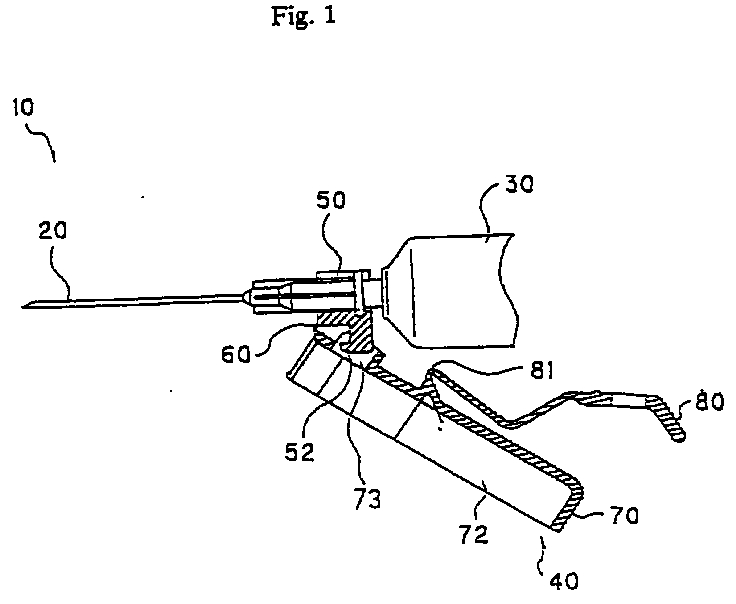
- FIG. 1 to FIG. 11 show a first embodiment of the present invention.
- numeral 10 denotes a medical syringe 10 which includes, a syringe main body 30 having a needle 20 mounted at the extreme end thereof and a cap 40 covering the needle 20 of the syringe main body 30, when they are roughly classified.
- the cap 40 includes a cap securing portion 50 secured at the extreme end of the syringe main body 30 and a cap main body 70 pivotally coupled with the cap securing portion 50 through a hinge portion 60, when they are further roughly classified.
- the cap 40 is molded from thermoplastic synthetic resin such as, for example, PP and the like having suitable rigidity and elasticity as a integral unit and subjected to sterilizing treatment after it is molded.
- the cap securing portion 50 is molded to a hollow cylindrical shape and has a mounting portion 51 formed thereinto, the mounting portion 51 having a C-shaped cross section with its upper surface opened so that the extreme end of the syringe main body 30 gets thereinto.
- the extreme end of the syringe main body 30 is mounted from the upper open surface of the mounting portion 51 making use of the elasticity of resin and the mounting portion 51 secured to the extreme end of the syringe main body 30 making use of the restoring force of resin.
- the hinge portion 60 has a thin wall structure and couples the lower end of the cap securing portion 50 with the lower end of the cap main body 70.
- the cap main body 70 includes an accommodating portion 71 for accommodating the needle 20 and a cut-out portion 72 which communicates with the accommodating portion 71 and into and from which the needle 20 can go and out.
- the cap main body 70 is formed to a hollow cylindrical shape and the entire length thereof is set longer than the needle 20.
- the cap main body 70 has a groove formed to the interior thereof as shown in FIG. 7 and FIG. 8, the groove having an U-shaped cross section with its upper surface opened.
- the groove has a width set greater than the diameter of the needle 20 as well as an entire length set longer than the needle 20.
- the interior of the groove of the cap main body 70 is arranged as the accommodating portion 71 for accommodating the needle 20 and the open upper surface of the groove is arranged as the cut-out portion 72 into and from which the needle 20 can and out.
- the cut-out portion 72 is formed to an elliptical shape having a major axis in the axial direction of the needle 20 as shown in FIG. 4.
- the cap main body 70 includes an operating handle 80 used for opening and closing operation as shown in FIG. 3 and FIG. 8 and an end of the operating handle 80 is coupled with the bottom surface of the cap main body 70 through a thin wall portion 81.
- two breakable breaking portions 90, 91 are formed between the cap securing portion 50 and the cap main body 70.
- the first breaking portion 90 which is used to couple the upper end of the cap securing portion 50 with the upper end of the cap main body 70, is formed to a pair on the right and left sides and has a thin wall structure.
- the second breaking portion 91 is formed between the cap securing portion 50 and the operating handle 80 and has a thin wall structure.
- the cap securing portion 50 and the cap main body 70 are coupled with each other through the operating handle 80 having the second breaking portion 91.
- breaking portion 90, 91 are formed at two positions in the embodiment shown in the drawings, they may be formed at one position or at three or more positions.
- a locking means in use and a locking means in disposal between the cap securing portion 50 and the cap main body 70 locks the cap main body 70 to the cap securing portion 50 at the position for use (refer to FIG. 1) where the needle 20 is exposed by turning the cap main body 70 from an accommodating position (refer to FIG. 2) where the needle 20 is accommodated in the accommodating portion 71 of the cap main body 70 on the hinge portion 60.
- the locking means in disposal turns the cap main body 70 in a reverse direction from the position for use (refer to FIG.
- the locking means in use is composed of a locking projection 52 projecting from the bottom of the cap securing portion 50 downward and a locking groove 73 which is formed on the bottom of the cap main body 70 and into which the locking projection 52 gets, as shown in FIG. 1 and FIG. 8.
- the extreme end of the locking projection 52 includes a hook portion 53 projecting in an L-shape toward the extreme end of the needle 20 as shown in FIG. 8. Further, the aforesaid second breaking portion 91 is formed to the lower end of the hook portion 53 which is continued to the operating handle 80 through the breaking portion 91 when molded.
- the locking groove 73 is formed to a long rectangular shape in the axial direction of the needle 20 and the right to left width of the groove is set less than the thickness of the locking projection 52 as shown in FIG. 5. Therefore, the locking projection 52 is inserted into the locking groove 73 making use of the elasticity of resin and held therein by the elastic restoring force and frictional force of resin.
- the locking projection 52 is formed to the cap securing portion 50 and the locking groove 73 is formed to the cap main body 70, respectively in the embodiment shown in the drawings
- the locking groove may be formed to the cap securing portion 50 and the locking projection may be formed to the cap main body 70, respectively on the contrary
- the locking means in disposal is composed of the above locking projection 52 formed to the cap securing portion 50 and a locking hole 82 which is formed at an intermediate position of the operating handle 80 in the lengthwise direction thereof and into which the locking projection 52 gets.
- the above locking hole 82 is formed to a long rectangular shape in the axial direction of the needle 20 likewise the locking groove 73 of the cap main body 70. Further, it suffices only to set the right to left groove width of the locking hole 82 less than the thickness of the locking projection 52. Thus, the locking hole 82 cannot be removed from the locking projection 52 in such a manner that the hook portion 53 of the locking projection 52 inserted into the locking hole 82 is hooked to the edge of the locking hole 82.
- the locking hole 82 may be arranged to a structure similar to that of the locking groove 73 and use the elastic restoring force and frictional force of resin.
- the locking projection 52 is formed to the cap securing portion 50 and the locking hole 82 is formed to the operating handle 80, respectively in the embodiment shown in the drawings, the locking hole may be formed to the cap securing portion 50 and the locking projection may be formed to the operating handle 80, respectively on the contrary. Further, it is sufficient only to form one of concave/convex portions which are engaged with each other to the cap securing portion 50 and the other of them to one or both of the cap main body 70 and the operating handle 80 thereof, respectively as the locking means at disposal.
- the syringe main body 30 is mounted to the mounting portion 51 of the cap securing portion 50 as shown in FIG. 2 as well as when the needle 20 is not yet used, the cap main body 70 is secured to the cap securing portion 50 through the first breaking portion 90. Further, the cap main body 70 is secured to the cap securing portion 50 through the second breaking portion 91 of the operating handle 80.
- the unused needle 20 is accommodated in the accommodating portion 71 of the cap main body 70 as shown in FIG. 2, it is in a safe and sanitary state.
- cap main body 70 is coupled with the cap securing portion 50 through the first and second breaking portions 90, 91, the cap main body 70 is also prevented from being carelessly opened.
- the cap main body 70 turns on the hinge portion 60 as shown in FIG. 1 and FIG. 10. At the time, the needle 20 slips out from the accommodating portion 71 through the cut-out portion 72 of the cap main body 70.
- the groove width of the locking groove 73 of the cap main body 70 is widened by the elastic force of resin by being pressed by the locking projection 52 of the cap securing portion 50, so that the locking projection 52 gets into the locking groove 73 in a confined state.
- the cap main body 70 is locked to the cap securing portion 50 to thereby prevent the swing of the cap main body 70 when the exposed needle 20 is used.
- the cap main body 70 turns in the reverse direction on the hinge portion 60 as shown in FIG. 11 and FIG. 12 At the time, the used needle 20 gets into the accommodating portion 71 again through the cut-out portion 72 of the cap main body 70.
- the tip of the used needle 20 is abutted against the bottom of the cap main body 70 and the turn of the cap main body 70 is stopped.
- the operating handle 80 When the operating handle 80 is further pressed, the operating handle 80 is bent to an approximately V-shape by the elastic force of resin and the position of the locking groove 73 of the cap main body 70 coincides with the position of the locking projection 52 of the cap securing portion 50 as shown in FIG. 12.
- the cap main body 70 is locked to the cap securing portion 50, so that the cap main body 70 is prevented from being carelessly opened as shown in FIG. 12.
- cap main body 70 Since the cap main body 70 is in the upwardly bent state with respect to the cap securing portion 50 as shown in FIG. 12, it can be easily determined that the cap main body 70 is already used from the outside appearance thereof.
- the existence of the operating handle 80 prevents a hand from getting in touch with the vicinity of the tip of the used needle 20 or the tip from facing toward the direction of an operator. Thus, there is no possibility that the needle tip erroneously pierces or comes into touch with the hand of the operator and the needle in a safe and sanitary state.
- FIG. 13 to FIG. 15 show a second embodiment of the present invention, wherein FIG. 13 is a plan view of a portion of an unused syringe, FIG. 14 is a view, partly in cross section, of a portion of the syringe of FIG. 13 showing the state that a cap main body is locked to a position for use and FIG. 15 is a view, partly in cross section, of a portion of the syringe of FIG. 13 showing the state that the cap main body of FIG. 13 is locked to a position for disposal.
- the second embodiment forms a locking projection 54 of a cap securing portion 50 to an anchor shape.
- a locking hole 82 of an operating handle 80 is formed a little smaller than the locking projection 54 of the cap securing portion 50.
- the removal of the locking projection 54 of the cap securing portion 50 can be made more difficult.
- the locking projection 54 of the cap securing portion 50 is formed to the anchor shape in the second embodiment, it is not limited thereto and may be formed to a canoe shape.
- numeral 10 denotes a medical syringe which includes, a syringe main body 30 having a needle 20 mounted at the extreme end thereof and a cap 40 covering the needle 20 of the syringe main body 30, when they are roughly classified.
- the cap 40 includes a cap securing portion 50 secured to the extreme end of the syringe main body 30 and a cap main body 70 pivotally coupled with the cap securing portion 50 through a hinge portion 60.
- the cap 40 is molded from thermoplastic synthetic resin such as, for example, PP and the like having suitable rigidity and elasticity as a integral unit and subjected to sterilizing treatment after it is molded.
- the cap securing portion 50 is molded to a hollow cylindrical shape and the interior of the cap securing portion 50 has a mounting portion 51 formed thereto, the mounting portion 51 having a C-shaped cross section with its upper surface opened so that the extreme end of the syringe main body 30 gets thereinto.
- the syringe main body 30 is mounted to the mounting portion 51 from the upper open surface thereof making use of the elasticity of resin of the extreme end of the syringe main body 30 and the mounting portion 51 is secured to the extreme end of the syringe main body 30 making use of the restoring force of resin.
- the hinge portion 60 has a thin wall structure and couples the lower end of the cap securing portion 50 with the lower end of the cap main body 70.
- the cap main body 70 includes an accommodating portion 71 for accommodating the needle 20 and a cut-out portion 72 which communicates with the accommodating portion 71 and into and from which the needle 20 can go and out.
- the cap main body 70 is formed to a hollow cylindrical shape and the entire length thereof is set longer than the needle 20.
- the cap main body 70 has a groove formed to the interior thereof as shown in FIG. 17 and FIG. 19, the groove having an U-shaped cross section with its upper surface opened.
- the groove has a width set greater than the diameter of the needle 20 as well as an entire length set longer than the needle 20.
- the interior of the groove of the cap main body 70 is arranged as the accommodating portion 71 for accommodating the needle 20 and the upper open surface of the groove is arranged as a cut-out portion 72 into and from which the needle 20 can go and out. Further, the cut-out portion 72 is formed to a long rectangular shape in the axial direction of the needle 20.
- the interior of the accommodating portion 71 is divided into two portions or a vacant accommodating portion used when needle is not used 73 (hereinafter, simply referred to vacant accommodating portion 73) which faces to the cut-out portion 72 and accommodates the unused needle 20 and a vacant accommodating portion used when needle is disposed of 74 (hereinafter, simply referred to vacant accommodating portion 74) which communicates with the vacant accommodating portion 73 and accommodates the needle 20 after it is used, and the accommodating portion 71 has a projection 75 projecting therein. Both the vacant accommodating portions 73, 74 communicate with each other through a communicating passage 76 through which the needle 20 can pass.
- a communicating passage 76 through which the needle 20 can pass.
- the projection 75 laterally projects to form a triangular shape and has an upper surface inclining downward to an free end.
- the used needle 20 goes down while being guided by the upper taper surface of the projection 75 and drops onto the bottom of the accommodating portion 71, that is, onto the vacant accommodating portion 74.
- the lower surface of the projection 75 is formed to a reverse taper surface which inclines downward to the free end as shown in FIG. 24.
- the used needle 20 which reaches the terminal end of the vacant accommodating portion 74 and then goes thereinto is difficult to go out from the vacant accommodating portion 74 because the exit of the vacant accommodating portion 74 is narrowed by reversely tapered lower surface of the projection 75.
- the projection 75 projects to form the triangular shape in the embodiment shown in the drawings, it may project to form a rectangular shape or a semicircular shape.
- a spring means is formed between the cap securing portion 50 and the cap main body 70 as shown in FIG. 18 and FIG. 20.
- the spring means urges the cap main body 70 to a direction in which the cap main body 70 is secured to the cap securing portion 50 at a position for use (refer to FIG. 16) where the needle 20 is exposed by turning the cap main body 70 on the above hinge portion 60 as well as urges the cap main body 70 toward the direction where the needle 20 is located in the accommodating portion 71 when the cap main body 70 is reversed on the hinge portion 60.
- the above spring means is composed of a spring hinge 80 bent to a U-shape across the hinge portion 60.
- the spring hinge 80 has an end coupled with the cap securing portion 50 through a thin wall portion 81 and the other portion coupled with the cap main body 70 through a thin wall portion 82 as shown in FIG. 20.
- the spring hinge 80 bent to the U-shape is used in the embodiment shown in the drawings as the spring means, the spring means is not limited the spring hinge, the spring hinge 80 is not limited to the U-shape and any structure may be used so long as its urging direction is reversed in the midway of the opening and closing of the cap main body 70.
- a stopper means is formed between the cap securing portion 50 and the cap main body 70 to regulate the rotational angle of the cap main body 70 with respect to the cap securing portion 50 at the position where the cap main body 70 is closed.
- the above stopper means is formed to the cap main body 70, and more specifically it is composed of a pair of right and left stopper pieces 77, 77 extending rearward from both the right and left sides of the cap main body 70 toward the cap securing portion 50 as shown in FIG. 18 to FIG. 20.
- the right and left stopper pieces 77 regulate the rotational angle of the cap main body 70 by the abutment of confronting inside stepped portions against the end surface of the cap securing portion 50.
- the unused needle 20 is accommodated in the vacant accommodating portion 73 in an unused state at the position where the rotational angel is regulated by the right and left stopper pieces 77.
- the cap main body 70 stops once at the position where the stepped portions of the right and left stopper piece pieces 77 are abutted against the end surface of the cap securing portion 50.
- the cap main body 70 is further rotated upward, the right and left stoppers 77 are pressed by the cap securing portion 50 and opened outside in the right and left directions against the elastic force of resin.
- the cap main body 70 is bent to a V-shape upward as shown in FIG. 25.
- the right and left stopper pieces 77 are formed to the cap main body 70 as the stopper means in the embodiment shown in the drawings, it may be formed to the cap securing portion 50 side or the stepped portions formed to the inside surface of the stopper pieces 77 may be formed to the cap securing portion 50 side.
- the needle 20 is accommodated in the vacant accommodating portion 73 as shown in FIG. 17.
- the needle 20 is in a safe and sanitary state.
- the cap main body 70 When the cap main body 70 is pulled downward, the cap main body 70 turns downward on the hinge portion 60 as shown in FIG. 16.
- the interval between both the ends of the spring hinge 80 is increased.
- the restoring force of the spring hinge 80 applies an urging force for closing the cap main body 70 against the force for opening the cap main body 70.
- the cap main body 70 when the cap main body 70 is to be opened, the cap main body 70 must be pulled against the urging force of the spring hinge 80.
- the cap main body 70 When the cap main body 70 is opened to its midway position, the interval between both the ends of the spring hinge 80 is decreased on the contrary. As a result, the cap main body 70 is vigorously opened by the accumulated elastic force of the spring hinge 80 even if the force for pulling the cap main body 70 is released.
- the spring hinge 80 returns to a stable state and the cap main body 70 is kept in the open state.
- the cap main body 70 can be kept in the open state and when the exposed needle 20 is used, the swing of the cap main body 70 can be prevented.
- the needle 20 After the needle 20 is used, it is sufficient only to press the cap main body 70 toward the hinge portion 60 side thereof, for example, to press the lower surface thereof upward.
- the cap main body 70 When the cap main body 70 is pressed upward, the cap main body 70 turns upward and returns on the hinge portion 60 as shown in FIG. 25.
- the used needle 20 gets into the vacant accumulating portion 73 through the cut-out portion 72 of the cap main body 70 as shown in FIG. 23.
- the cap main body 70 When the cap main body 70 is further pressed upward, the used needle 20 goes down through the communicating passage 76 while being guided by the upper taper surface of the projection 75 and drops toward the bottom of the accommodating portion 71, that is, the vacant accommodating portion 74 as shown in FIG. 24.
- the used needle 20 goes to the inner part of the vacant accommodating portion 74 by being guided by the lower surface tapered reversely of the projection 75 when the cap main body 70 tends to open, thus the needle 20 is difficult to go out from the vacant accommodating portion 74.
- cap main body 70 Since the cap main body 70 is in the state that the upper portion thereof is bent upward with respect to the cap securing portion 50 as shown in FIG. 25, it can be easily determined from the outside appearance thereof that the cap main body 70 is already used.
- the operator can open and close the cap main body 70 while holding it, a hand does not get in touch with the vicinity of the tip of the used needle 20 or the tip does not face toward the direction of an operator.
- the needle tip erroneously pierces or comes into touch with the hand of the operator, by which a safe and sanitary state can be achieved.
- FIG. 26 showing a fourth embodiment of the present invention and is a plan view of a portion of a syringe illustrating the state that a cap main body is opened.
- the forth embodiment has a feature that an operating projection 83 is formed a spring hinge 80 as shown in FIG. 26.
- the operating projection 83 projects outward from the center of the outer periphery of the U-shaped portion of the spring hinge 80 to form a Y-shape as shown in FIG. 26.
- the operator can open and close cap main body 70 while holding the operating projection 83.
- the shape of the operating projection 83, the position where it is formed and the like are not limited to those of the forth embodiment shown in FIG. 26 and the operating projection 83 may be formed to the cap main body 70 side.
Abstract
Disclosed is a syringe with a cap including a
syringe main body (30) having a needle attached to the
extreme end thereof and the cap (40) for covering the needle
(20) of the syringe main body (30), wherein the cap (40)
includes a cap securing portion (50) secured to the extreme
end of the syringe main body (30) and a cap main body (70)
pivotally coupled with the cap securing portion (50) through
a hinge portion (60) and the cap main portion (70) includes
an accommodating portion for accommodating the needle (20)
and a cut-out portion (72) which communicates with the
accommodating portion and into and from which the needle
(20) can go and out, the syringe with cap comprising
securing means (52, 73, 80) capable of securing the cap to
the cap securing portion (50) when the syringe is used.
Description
The present invention relates to a syringe with a
cap, and more specifically, to a syringe with a cap capable
of securely locking the cap at an open position and a closed
position.
Conventionally, there is known a syringe including a
syringe main body having a needle mounted at the extreme end
thereof and a cap for covering the needle of the syringe
main body as this type of the syringe (for example, Japanese
Utility Model Application Laid-Open No. Sho 63-189255,
Japanese Utility Model Application Laid-Open No. Sho 64-17248,
Japanese Utility Model Application Laid-Open No. Hei
1-62849 and the like).
The aforesaid conventional cap includes a cap
securing portion secured at the extreme end of the syringe
main body and a cap main body pivotally coupled with the cap
securing portion though a hinge portion.
The aforesaid conventional cap main body includes an
accommodating portion for accommodating a needle and a cutout
portion which communicates with the accommodating
portion and into and from which the needle can go and out.
However, the aforesaid conventional syringe has a
first problem that when an injection is effected by opening
the cap by turning it on the hinge portion, the cap swings
from the hinge portion and disturbs medical treatment.
Further, there is a second problem that when the cap
is closed by being turned in a reverse direction on the
hinge portion after the syringe is used, since the syringe
has the same outside appearance as that of an unused
syringe, it cannot be determined whether the needle is
already used or not yet used.
Taking the above problems into consideration, an
object of the present invention is to provide a syringe with
a cap capable of preventing the swing of the cap when the
syringe is used.
Another object of the present invention is to be
able to determine whether a needle is not yet used or
already used from the outside appearance thereof in the
state that the needle is covered with the cap.
Still another object of the present invention is to
be able to more securely determine whether a needle is not
yet used or already used.
A further object of the present invention is to
prevent a used needle from being unnecessarily exposed from
a cap.
According to the present invention for achieving the
above objects, there is provided a syringe with a cap
including a syringe main body having a needle attached to
the extreme end thereof and the cap for covering the needle
of the syringe main body, wherein the cap includes a cap
securing portion secured to the extreme end of the syringe
main body and a cap main body pivotally coupled with the cap
securing portion through a hinge portion and the cap main
body includes an accommodating portion for accommodating
the needle and a cut-out portion which communicates with the
accommodating portion and into and from which the needle can
go and out, the aforesaid syringe with cap comprising
securing means capable of securing the cap to the cap
securing portion when the syringe is used.
Therefore, in the present invention, the syringe can
be used in the state that the cap is secured.
The present invention includes a locking means in
use which is interposed between the cap securing portion and
the cap main body and locks the cap main body to the cap
securing portion at a position for use where the needle is
exposed by turning the cap main body from an accommodating
position where the needle is accommodated in the
accommodating portion of the cap main body on the hinge
portion.
Therefore, according to the present invention, the
cap main body is turned on the hinge portion and exposes the
needle from the state that the needle is covered with the
cap. The cap main body is secured to the cap securing
portion by the locking means in use at the position for use
so that the swing of the cap main body is prevented.
The present invention includes a locking means in
disposal which is interposed between the cap securing
portion and the cap main body for turning the cap main body
in a reverse direction from the position for use where the
needle is disposed on the hinge portion to thereby
accommodated the used needle to the accommodating portion
and locking the cap main body to the cap securing portion at
a position for disposal different from the accommodating
position.
Therefore, according to the present invention, after
the needle is used, the cap main body is turned in the
reverse direction on the hinge portion to thereby
accommodate the used needle in the accommodating portion of
the cap main body.
At the time, the cap main body is secured, for
example, by the locking means in disposal at the position
for disposal different from the accommodating position with
respect to the cap fixing portion.
As a result, whether the needle is already used or
it is not yet used can be determined by observing the state
of the needle accommodated in the cap main body. In
addition to the above, since the cap main body is secured to
the cap securing portion by the locking means in disposal,
there is no possibility that the used needle is carelessly
exposed.
The present invention includes a breakable breaking
portion which is interposed between the cap securing portion
and the cap main body at the position where the unused
needle is accommodated in the accommodating portion of the
cap main body to secure the cap main body to the cap
securing portion.
That is, the needle can be made to a usable state
when it is exposed by breaking the breaking portion and
turning the cap main body on the hinge portion.
As a result, whether the needle is already used or
it is not yet used can be determined by observing the state
of the breaking portion. In addition to the above, since
the cap main body is secured to the cap securing portion
through the breaking portion when the needle is not yet
used, there is no possibility that the needle is carelessly
exposed, thus the needle can be kept in a safe and sanitary
state.
The present invention includes a spring means which
is interposed between the cap securing portion and the cap
main body, the spring means urging the cap main body toward
a direction for securing the cap main body to the cap securing
portion at the position for use where the needle is exposed
by turning the cap main body on the hinge portion as well as
urging the cap main body toward a position where the needle
is located in the accommodating portion when the cap main
body is turned in the reverse direction on the hinge
portion.
Thus, according to the present invention, when the
cap main body is turned toward an open direction on the
hinge portion against the urging force of the spring means
from an unused state, the needle is exposed to the outside
through the cut-out portion of the cap main body.
At the position for use where the needle is exposed,
the urging direction of the spring means is reversed so that
the cap main body is urged toward the cap securing portion
by the urging force of the spring means. As a result, the
cap main body can be prevented from being carelessly swung
when the needle is used.
When the cap main body is turned toward a close
direction on the hinge portion against the urging force of
the spring means after the needle is used, the used needle
is accommodated in the accommodating portion of the cap main
body.
At the time, the urging direction of the spring
means is reversed so that the cap main body is urged toward
the position where the used needle is located in the
accommodating portion by the urging force of the spring
means.
As a result, it can be prevented that the cap main
body is carelessly opened and the used needle is exposed.
In the present invention, the interior of the
accommodating portion of the cap main body is divided into
two portions or a vacant accommodating portion used when
needle is not used which faces to the cut-out portion and
accommodates the unused needle and a vacant accommodating
portion used when needle is disposed of which communicates
with the above vacant accommodating portion and accommodates
the needle after it is used and the accommodating portion
forms a projection projecting therein.
Consequently, in the present invention, the unused
needle is accommodated in the vacant accommodating portion
used when needle is not used of the cap main body. Since
the vacant accommodating portion used when needle is not
used faces to the cut-out portion, the cap main body can be
promptly released.
On the other hand, the used needle gets into the
vacant accommodating portion used when needle is not used
through the cut-out of the cap main body. Next, the used
needle further goes to an inner part while avoiding the
projection projecting in the accommodating portion and is
accommodated in the vacant accommodating portion used when
needle is disposed of.
As a result, since the used needle is located in the
inner part of the accommodating portion, even if the cap
main body is turned toward the open direction on the hinge
portion, it is abutted against the projection and the
careless exposure thereof to the outside can be prevented.
Further, since the needle, when it is already used,
is accommodated in the position different from that where
the needle is accommodated when it is not yet used, whether
the needle is already used or not yet used can be easily
determined from the outside appearance thereof.
In the present invention, the interior of the
accommodating portion of the cap main body is divided into
two portions or a vacant accommodating portion used when
needle is not used which faces to the cut-out portion and
accommodates the unused needle and a vacant accommodating
portion used when needle is disposed of which communicates
with the above vacant accommodating portion and accommodates
the needle after it is used and the accommodating portion
forms a projection projecting therein.
Further, the present invention includes a spring
means which is formed between the cap securing portion and
the cap main body, the spring means urging the cap main body
toward a direction for securing the cap main body to the cap
securing portion at the position for use where the needle is
exposed by turning the cap main body on the hinge portion as
well as urging the cap main body toward a position where the
used needle is located in the vacant accommodating portion
used when needle is disposed of when the cap main body is
turned in a reverse direction on the hinge portion.
FIG. 2 is a plan view of an unused syringe;
FIG. 3 to FIG. 8 show an unused cap, respectively, wherein:
FIG. 11 and FIG. 12 show the state that the cap main body is locked to a disposing position, respectively, wherein:
FIG. 18 to FIG. 22 show a cap in a molding process, wherein:
FIG. 23 and FIG. 24 show accommodating positions of a needle, wherein:
FIG. 1 to FIG. 11 show a first embodiment of the
present invention.
In FIG. 2, numeral 10 denotes a medical syringe 10
which includes, a syringe main body 30 having a needle 20
mounted at the extreme end thereof and a cap 40 covering the
needle 20 of the syringe main body 30, when they are roughly
classified.
As shown in FIG. 2, the cap 40 includes a cap
securing portion 50 secured at the extreme end of the
syringe main body 30 and a cap main body 70 pivotally
coupled with the cap securing portion 50 through a hinge
portion 60, when they are further roughly classified. The
cap 40 is molded from thermoplastic synthetic resin such as,
for example, PP and the like having suitable rigidity and
elasticity as a integral unit and subjected to sterilizing
treatment after it is molded.
As shown in FIG. 6 and FIG. 8, the cap securing
portion 50 is molded to a hollow cylindrical shape and has a
mounting portion 51 formed thereinto, the mounting portion
51 having a C-shaped cross section with its upper surface
opened so that the extreme end of the syringe main body 30
gets thereinto. The extreme end of the syringe main body 30
is mounted from the upper open surface of the mounting
portion 51 making use of the elasticity of resin and the
mounting portion 51 secured to the extreme end of the
syringe main body 30 making use of the restoring force of
resin.
As shown in FIG. 8, the hinge portion 60 has a thin
wall structure and couples the lower end of the cap securing
portion 50 with the lower end of the cap main body 70.
As shown in FIG. 7 and FIG. 8, the cap main body 70
includes an accommodating portion 71 for accommodating the
needle 20 and a cut-out portion 72 which communicates with
the accommodating portion 71 and into and from which the
needle 20 can go and out.
As shown in FIG. 7 and FIG. 8, the cap main body 70
is formed to a hollow cylindrical shape and the entire
length thereof is set longer than the needle 20.
More specifically, the cap main body 70 has a groove
formed to the interior thereof as shown in FIG. 7 and FIG.
8, the groove having an U-shaped cross section with its
upper surface opened. The groove has a width set greater
than the diameter of the needle 20 as well as an entire
length set longer than the needle 20. The interior of the
groove of the cap main body 70 is arranged as the
accommodating portion 71 for accommodating the needle 20 and
the open upper surface of the groove is arranged as the cut-out
portion 72 into and from which the needle 20 can and
out. Further, the cut-out portion 72 is formed to an
elliptical shape having a major axis in the axial direction
of the needle 20 as shown in FIG. 4.
On the other hand, the cap main body 70 includes an
operating handle 80 used for opening and closing operation
as shown in FIG. 3 and FIG. 8 and an end of the operating
handle 80 is coupled with the bottom surface of the cap main
body 70 through a thin wall portion 81.
As shown in FIG. 8, two breakable breaking portions
90, 91 are formed between the cap securing portion 50 and
the cap main body 70.
As shown in FIG. 4 and FIG. 8, the first breaking
portion 90, which is used to couple the upper end of the cap
securing portion 50 with the upper end of the cap main body
70, is formed to a pair on the right and left sides and has
a thin wall structure.
As shown in FIG. 6 and FIG. 8, the second breaking
portion 91 is formed between the cap securing portion 50 and
the operating handle 80 and has a thin wall structure. The
cap securing portion 50 and the cap main body 70 are coupled
with each other through the operating handle 80 having the
second breaking portion 91.
Note, although the breaking portion 90, 91 are
formed at two positions in the embodiment shown in the
drawings, they may be formed at one position or at three or
more positions.
As shown in FIG. 8, there are provided a locking
means in use and a locking means in disposal between the cap
securing portion 50 and the cap main body 70. The locking
means in use locks the cap main body 70 to the cap securing
portion 50 at the position for use (refer to FIG. 1) where
the needle 20 is exposed by turning the cap main body 70
from an accommodating position (refer to FIG. 2) where the
needle 20 is accommodated in the accommodating portion 71 of
the cap main body 70 on the hinge portion 60. The locking
means in disposal turns the cap main body 70 in a reverse
direction from the position for use (refer to FIG. 1) where
the needle 20 is exposed on the hinge portion 60 to thereby
accommodate the used needle 20 to the accommodating portion
71 and locks the cap main body 70 to the cap securing
portion 50 at a position for disposal (refer to FIG. 11 and
FIG. 12) different from the accommodating position (refer to
FIG. 2).
First, the locking means in use is composed of a
locking projection 52 projecting from the bottom of the cap
securing portion 50 downward and a locking groove 73 which
is formed on the bottom of the cap main body 70 and into
which the locking projection 52 gets, as shown in FIG. 1 and
FIG. 8.
The extreme end of the locking projection 52
includes a hook portion 53 projecting in an L-shape toward
the extreme end of the needle 20 as shown in FIG. 8.
Further, the aforesaid second breaking portion 91 is formed
to the lower end of the hook portion 53 which is continued
to the operating handle 80 through the breaking portion 91
when molded.
The locking groove 73 is formed to a long
rectangular shape in the axial direction of the needle 20
and the right to left width of the groove is set less than
the thickness of the locking projection 52 as shown in FIG.
5. Therefore, the locking projection 52 is inserted into
the locking groove 73 making use of the elasticity of resin
and held therein by the elastic restoring force and
frictional force of resin.
Note, although the locking projection 52 is formed
to the cap securing portion 50 and the locking groove 73 is
formed to the cap main body 70, respectively in the
embodiment shown in the drawings, the locking groove may be
formed to the cap securing portion 50 and the locking
projection may be formed to the cap main body 70,
respectively on the contrary Further, it is sufficient
only to form one of concave/convex portions which are
engaged with each other to the cap securing portion 50 and
the other of them to the cap main body 70, respectively as
the locking means in use.
As shown in FIG. 8 and FIG. 12, the locking means in
disposal is composed of the above locking projection 52
formed to the cap securing portion 50 and a locking hole 82
which is formed at an intermediate position of the operating
handle 80 in the lengthwise direction thereof and into which
the locking projection 52 gets.
As shown in FIG. 4, the above locking hole 82 is
formed to a long rectangular shape in the axial direction of
the needle 20 likewise the locking groove 73 of the cap main
body 70. Further, it suffices only to set the right to left
groove width of the locking hole 82 less than the thickness
of the locking projection 52. Thus, the locking hole 82
cannot be removed from the locking projection 52 in such a
manner that the hook portion 53 of the locking projection 52
inserted into the locking hole 82 is hooked to the edge of
the locking hole 82.
Note, the locking hole 82 may be arranged to a
structure similar to that of the locking groove 73 and use
the elastic restoring force and frictional force of resin.
Although the locking projection 52 is formed to the
cap securing portion 50 and the locking hole 82 is formed to
the operating handle 80, respectively in the embodiment
shown in the drawings, the locking hole may be formed to the
cap securing portion 50 and the locking projection may be
formed to the operating handle 80, respectively on the
contrary. Further, it is sufficient only to form one of
concave/convex portions which are engaged with each other to
the cap securing portion 50 and the other of them to one or
both of the cap main body 70 and the operating handle 80
thereof, respectively as the locking means at disposal.
Next, a sequence for using the cap 40 arranged as
described above will be described.
First, the syringe main body 30 is mounted to the
mounting portion 51 of the cap securing portion 50 as shown
in FIG. 2 as well as when the needle 20 is not yet used, the
cap main body 70 is secured to the cap securing portion 50
through the first breaking portion 90. Further, the cap
main body 70 is secured to the cap securing portion 50
through the second breaking portion 91 of the operating
handle 80.
As a result, unless the first and second breaking
portions 90, 91 are not broken, it can be easily determined
that the needle 20 is not yet used from the outside view
thereof.
Since the unused needle 20 is accommodated in the
accommodating portion 71 of the cap main body 70 as shown in
FIG. 2, it is in a safe and sanitary state.
Further, since the cap main body 70 is coupled with
the cap securing portion 50 through the first and second
breaking portions 90, 91, the cap main body 70 is also
prevented from being carelessly opened.
Next, when the needle 20 is to be used, it suffices
only to bend the cap main body 70 downward while holding it
as shown in FIG. 9.
When the cap main body 70 is bent downward, the
first and second breaking portions 90, 91 are broken as
shown in, for example, FIG. 9.
Next, it is sufficient only to pull the operating
handle 80 of the cap main body 70 toward the direction of
the syringe main body 30 while holding the operating handle
80.
When the operating handle 80 is pulled as described
above, the cap main body 70 turns on the hinge portion 60 as
shown in FIG. 1 and FIG. 10. At the time, the needle 20
slips out from the accommodating portion 71 through the cut-out
portion 72 of the cap main body 70.
When the operating handle 80 is further pulled, the
locking groove 73 of the cap main body 70 is locked to the
locking projection 52 of the cap securing portion 50.
When the operating handle 80 is further pulled
strongly at the time, the groove width of the locking groove
73 of the cap main body 70 is widened by the elastic force
of resin by being pressed by the locking projection 52 of
the cap securing portion 50, so that the locking projection
52 gets into the locking groove 73 in a confined state.
As a result, the cap main body 70 is locked to the
cap securing portion 50 to thereby prevent the swing of the
cap main body 70 when the exposed needle 20 is used.
After the needle 20 is used, it suffices only to
press the operating handle 80 toward the tip direction of
the needle 20 while holding the operating handle 80.
When the operating handle 80 is pressed, the cap
main body 70 turns in the reverse direction on the hinge
portion 60 as shown in FIG. 11 and FIG. 12 At the time,
the used needle 20 gets into the accommodating portion 71
again through the cut-out portion 72 of the cap main body
70.
Then, the tip of the used needle 20 is abutted
against the bottom of the cap main body 70 and the turn of
the cap main body 70 is stopped.
When the operating handle 80 is further pressed, the
operating handle 80 is bent to an approximately V-shape by
the elastic force of resin and the position of the locking
groove 73 of the cap main body 70 coincides with the
position of the locking projection 52 of the cap securing
portion 50 as shown in FIG. 12.
When the operating handle 80 is pressed upward at
the time, the locking projection 52 gets into the locking
groove 73 as shown in FIG. 12.
Subsequently, when the pressure force for pressing
the operating handle 80 is released, the operating handle 80
bent to the approximately V-shaped is somewhat extended by
the restoring force of resin. At the time, the position of
the locking groove 73 relatively retracts a little. As a
result, when the operating handle 80 tends to come off
downward, the locking hole 82 cannot come off from the
locking projection 52 because the hook portion 53 of the
locking projection 52 is hooked to the edge of the locking
projection 52.
Therefore, the cap main body 70 is locked to the cap
securing portion 50, so that the cap main body 70 is
prevented from being carelessly opened as shown in FIG. 12.
Since the cap main body 70 is in the upwardly bent
state with respect to the cap securing portion 50 as shown
in FIG. 12, it can be easily determined that the cap main
body 70 is already used from the outside appearance thereof.
Further, the existence of the operating handle 80
prevents a hand from getting in touch with the vicinity of
the tip of the used needle 20 or the tip from facing toward
the direction of an operator. Thus, there is no possibility
that the needle tip erroneously pierces or comes into touch
with the hand of the operator and the needle in a safe and
sanitary state.
FIG. 13 to FIG. 15 show a second embodiment of the
present invention, wherein FIG. 13 is a plan view of a
portion of an unused syringe, FIG. 14 is a view, partly in
cross section, of a portion of the syringe of FIG. 13
showing the state that a cap main body is locked to a
position for use and FIG. 15 is a view, partly in cross
section, of a portion of the syringe of FIG. 13 showing the
state that the cap main body of FIG. 13 is locked to a
position for disposal.
As shown in FIG. 13 to FIG. 15, the second
embodiment forms a locking projection 54 of a cap securing
portion 50 to an anchor shape.
That is, a locking hole 82 of an operating handle 80
is formed a little smaller than the locking projection 54 of
the cap securing portion 50.
Note, in the description of the second embodiment,
portions arranged similarly to those of the first embodiment
described previously are denoted by the numerals and the
description thereof is omitted.
With this arrangement, when the locking projection
54 of the cap securing portion 50 is inserted into the
locking hole 82 of the operating handle 80 after a needle 20
is used as shown in FIG. 15, the locking projection 54
passes through the locking hole 82 by being pressed by the
edge of the locking hole 82 while being narrowed by the
elastic force of resin. When the locking projection 54 has
passed through the locking hole 82, it is expanded by the
restoring force of resin and cannot slip out from the
locking hole 82.
As a result, according to the second embodiment, the
removal of the locking projection 54 of the cap securing
portion 50 can be made more difficult.
Note, although the locking projection 54 of the cap
securing portion 50 is formed to the anchor shape in the
second embodiment, it is not limited thereto and may be
formed to a canoe shape.
Next, a third embodiment according to the present
invention will be described.
In FIG. 17, numeral 10 denotes a medical syringe
which includes, a syringe main body 30 having a needle 20
mounted at the extreme end thereof and a cap 40 covering the
needle 20 of the syringe main body 30, when they are roughly
classified.
As shown in FIG. 17, the cap 40 includes a cap
securing portion 50 secured to the extreme end of the
syringe main body 30 and a cap main body 70 pivotally
coupled with the cap securing portion 50 through a hinge
portion 60. When they are further roughly classified. The
cap 40 is molded from thermoplastic synthetic resin such as,
for example, PP and the like having suitable rigidity and
elasticity as a integral unit and subjected to sterilizing
treatment after it is molded.
As shown in FIG. 20 to FIG. 22, the cap securing
portion 50 is molded to a hollow cylindrical shape and the
interior of the cap securing portion 50 has a mounting
portion 51 formed thereto, the mounting portion 51 having a
C-shaped cross section with its upper surface opened so that
the extreme end of the syringe main body 30 gets thereinto.
The syringe main body 30 is mounted to the mounting portion
51 from the upper open surface thereof making use of the
elasticity of resin of the extreme end of the syringe main
body 30 and the mounting portion 51 is secured to the
extreme end of the syringe main body 30 making use of the
restoring force of resin.
As shown in FIG. 17 and FIG. 18, the hinge portion
60 has a thin wall structure and couples the lower end of
the cap securing portion 50 with the lower end of the cap
main body 70.
As shown in FIG. 21, the cap main body 70 includes
an accommodating portion 71 for accommodating the needle 20
and a cut-out portion 72 which communicates with the
accommodating portion 71 and into and from which the needle
20 can go and out.
As shown in FIG. 17, the cap main body 70 is formed
to a hollow cylindrical shape and the entire length thereof
is set longer than the needle 20.
More specifically, the cap main body 70 has a groove
formed to the interior thereof as shown in FIG. 17 and FIG.
19, the groove having an U-shaped cross section with its
upper surface opened. The groove has a width set greater
than the diameter of the needle 20 as well as an entire
length set longer than the needle 20. The interior of the
groove of the cap main body 70 is arranged as the
accommodating portion 71 for accommodating the needle 20 and
the upper open surface of the groove is arranged as a cut-out
portion 72 into and from which the needle 20 can go and
out. Further, the cut-out portion 72 is formed to a long
rectangular shape in the axial direction of the needle 20.
As shown in FIG. 23, the interior of the
accommodating portion 71 is divided into two portions or a
vacant accommodating portion used when needle is not used 73
(hereinafter, simply referred to vacant accommodating
portion 73) which faces to the cut-out portion 72 and
accommodates the unused needle 20 and a vacant accommodating
portion used when needle is disposed of 74 (hereinafter,
simply referred to vacant accommodating portion 74) which
communicates with the vacant accommodating portion 73 and
accommodates the needle 20 after it is used, and the
accommodating portion 71 has a projection 75 projecting
therein. Both the vacant accommodating portions 73, 74
communicate with each other through a communicating passage
76 through which the needle 20 can pass.
As shown in FIG. 23, the projection 75 laterally
projects to form a triangular shape and has an upper surface
inclining downward to an free end. As a result, the used
needle 20 goes down while being guided by the upper taper
surface of the projection 75 and drops onto the bottom of
the accommodating portion 71, that is, onto the vacant
accommodating portion 74.
Whereas, the lower surface of the projection 75 is
formed to a reverse taper surface which inclines downward to
the free end as shown in FIG. 24. Thus, the used needle 20
which reaches the terminal end of the vacant accommodating
portion 74 and then goes thereinto is difficult to go out
from the vacant accommodating portion 74 because the exit of
the vacant accommodating portion 74 is narrowed by reversely
tapered lower surface of the projection 75.
Note, although the projection 75 projects to form
the triangular shape in the embodiment shown in the
drawings, it may project to form a rectangular shape or a
semicircular shape.
Further, a spring means is formed between the cap
securing portion 50 and the cap main body 70 as shown in
FIG. 18 and FIG. 20. The spring means urges the cap main
body 70 to a direction in which the cap main body 70 is
secured to the cap securing portion 50 at a position for use
(refer to FIG. 16) where the needle 20 is exposed by turning
the cap main body 70 on the above hinge portion 60 as well
as urges the cap main body 70 toward the direction where the
needle 20 is located in the accommodating portion 71 when
the cap main body 70 is reversed on the hinge portion 60.
As shown in FIG. 20, the above spring means is
composed of a spring hinge 80 bent to a U-shape across the
hinge portion 60. The spring hinge 80 has an end coupled
with the cap securing portion 50 through a thin wall portion
81 and the other portion coupled with the cap main body 70
through a thin wall portion 82 as shown in FIG. 20.
Note, although the spring hinge 80 bent to the U-shape
is used in the embodiment shown in the drawings as the
spring means, the spring means is not limited the spring
hinge, the spring hinge 80 is not limited to the U-shape and
any structure may be used so long as its urging direction is
reversed in the midway of the opening and closing of the cap
main body 70.
Further, as shown in FIG. 17, a stopper means is
formed between the cap securing portion 50 and the cap main
body 70 to regulate the rotational angle of the cap main
body 70 with respect to the cap securing portion 50 at the
position where the cap main body 70 is closed.
In this embodiment, the above stopper means is
formed to the cap main body 70, and more specifically it is
composed of a pair of right and left stopper pieces 77, 77
extending rearward from both the right and left sides of the
cap main body 70 toward the cap securing portion 50 as shown
in FIG. 18 to FIG. 20.
As shown in FIG. 19, the right and left stopper
pieces 77 regulate the rotational angle of the cap main body
70 by the abutment of confronting inside stepped portions
against the end surface of the cap securing portion 50.
As shown in FIG. 17, the unused needle 20 is
accommodated in the vacant accommodating portion 73 in an
unused state at the position where the rotational angel is
regulated by the right and left stopper pieces 77. When the
cap main body 70 is opened and the needle 20 is used and
then the cap main body 70 is closed again, the cap main body
70 stops once at the position where the stepped portions of
the right and left stopper piece pieces 77 are abutted
against the end surface of the cap securing portion 50.
Thereafter, when the cap main body 70 is further rotated
upward, the right and left stoppers 77 are pressed by the
cap securing portion 50 and opened outside in the right and
left directions against the elastic force of resin. As a
result, the cap main body 70 is bent to a V-shape upward as
shown in FIG. 25.
Note, although the right and left stopper pieces 77
are formed to the cap main body 70 as the stopper means in
the embodiment shown in the drawings, it may be formed to
the cap securing portion 50 side or the stepped portions
formed to the inside surface of the stopper pieces 77 may be
formed to the cap securing portion 50 side.
Next, a sequence for using the cap 40 arranged as
described above will be described.
First, when the needle 20 is not yet used, the
needle 20 is accommodated in the vacant accommodating
portion 73 as shown in FIG. 17. Thus, the needle 20 is in a
safe and sanitary state.
Next, when the needle 20 is to be used, it suffices
only to pull the cap main body 70 toward the side where the
hinge portion 60 exists, for example, downward while holding
both the right and left sides of the cap main body 70.
When the cap main body 70 is pulled downward, the
cap main body 70 turns downward on the hinge portion 60 as
shown in FIG. 16.
At the time, the interval between both the ends of
the spring hinge 80 is increased. As a result, the
restoring force of the spring hinge 80 applies an urging
force for closing the cap main body 70 against the force for
opening the cap main body 70.
Thus, when the cap main body 70 is to be opened, the
cap main body 70 must be pulled against the urging force of
the spring hinge 80.
When the cap main body 70 is opened to its midway
position, the interval between both the ends of the spring
hinge 80 is decreased on the contrary. As a result, the cap
main body 70 is vigorously opened by the accumulated elastic
force of the spring hinge 80 even if the force for pulling
the cap main body 70 is released.
When the cap main body 70 is opened by the above
operation, the spring hinge 80 returns to a stable state and
the cap main body 70 is kept in the open state.
Therefore, the cap main body 70 can be kept in the
open state and when the exposed needle 20 is used, the swing
of the cap main body 70 can be prevented.
After the needle 20 is used, it is sufficient only
to press the cap main body 70 toward the hinge portion 60
side thereof, for example, to press the lower surface
thereof upward.
When the cap main body 70 is pressed upward, the cap
main body 70 turns upward and returns on the hinge portion
60 as shown in FIG. 25.
At the time, since the interval between both the
ends of the spring hinge 80 is increased once, the cap main
body 70 must be pressed upward against the urging force of
the spring hinge 80. However, when the cap main body 70 is
pressed upward up to its midway point, the interval between
both the ends of the spring hinge 80 decreased accordingly.
As a result, even if the force for pressing the cap
main body 70 upward, the cap main body 70 is vigorously
closed by the accumulated elastic force of the spring hinge
80.
At the time, the used needle 20 gets into the vacant
accumulating portion 73 through the cut-out portion 72 of
the cap main body 70 as shown in FIG. 23.
When the cap main body 70 is further pressed upward,
the used needle 20 goes down through the communicating
passage 76 while being guided by the upper taper surface of
the projection 75 and drops toward the bottom of the
accommodating portion 71, that is, the vacant accommodating
portion 74 as shown in FIG. 24.
Therefore, when the used needle 20 is disposed of,
the used needle 20 goes to the inner part of the vacant
accommodating portion 74 by being guided by the lower
surface tapered reversely of the projection 75 when the cap
main body 70 tends to open, thus the needle 20 is difficult
to go out from the vacant accommodating portion 74.
Since the cap main body 70 is in the state that the
upper portion thereof is bent upward with respect to the cap
securing portion 50 as shown in FIG. 25, it can be easily
determined from the outside appearance thereof that the cap
main body 70 is already used.
Further, the operator can open and close the cap
main body 70 while holding it, a hand does not get in touch
with the vicinity of the tip of the used needle 20 or the
tip does not face toward the direction of an operator.
Thus, there is no possibility that the needle tip
erroneously pierces or comes into touch with the hand of the
operator, by which a safe and sanitary state can be
achieved.
FIG. 26 showing a fourth embodiment of the present
invention and is a plan view of a portion of a syringe
illustrating the state that a cap main body is opened.
The forth embodiment has a feature that an operating
projection 83 is formed a spring hinge 80 as shown in FIG.
26.
The operating projection 83 projects outward from
the center of the outer periphery of the U-shaped portion of
the spring hinge 80 to form a Y-shape as shown in FIG. 26.
According to the fourth embodiment, the operator can
open and close cap main body 70 while holding the operating
projection 83.
Note, the shape of the operating projection 83, the
position where it is formed and the like are not limited to
those of the forth embodiment shown in FIG. 26 and the
operating projection 83 may be formed to the cap main body
70 side.
Note, the respective embodiments shown in the
present invention are only examples for illustration and do
not restrict the present invention, thus the scope of the
present invention is shown by claims to be described below
and all the modifications contained in the scope of the
claims are covered by the prevent invention.
Claims (8)
- A syringe with a cap including a syringe main body having a needle attached to the extreme end thereof and the cap for covering the needle of the syringe main body, wherein the cap includes a cap securing portion secured to the extreme end of the syringe main body and a cap main body pivotally coupled with the cap securing portion through a hinge portion and said cap main body includes an accommodating portion for accommodating the needle and a cut-out portion which communicates with the accommodating portion and into and from which the needle can go and out, comprising securing means capable of securing said cap to said cap securing portion when said syringe is used.
- A syringe with a cap according to claim 1, wherein said securing means comprises locking means in use and said locking means in use is interposed between said cap securing portion and said cap main body and locks said cap main body to said cap securing portion at a position for use where said needle is exposed by turning said cap main body from an accommodating position where said needle is accommodated in the accommodating portion of said cap main body on said hinge portion.
- A syringe with a cap according to claim 2, wherein locking means in disposal is interposed between said cap securing portion and said cap main body for turning said cap main body in a reverse direction from the position for use where said needle is disposed on said hinge portion to cap main body in a reverse direction from the position for use where said needle is disposed on said hinge portion to thereby accommodated said used needle to said accommodating portion and locking said cap main body to said cap securing portion at a position for disposal different from said accommodating position.
- A syringe with a cap according to claim 2 or claim 3, wherein a breakable breaking portion is interposed between said cap securing portion and said cap main body at the position where said unused needle is accommodated in the accommodating portion of said cap main body to secure said cap main body to said cap securing portion .
- A syringe with a cap according to claim 1, wherein said securing means is composed of spring means interposed between said cap securing portion and said cap main body, said spring means urging said cap main body toward a direction for securing said cap main body to said cap securing portion at the position for use where said needle is exposed by turning said cap main body on said hinge portion as well as urging said cap main body toward a position where said needle is located in said accommodating portion when said cap main body is turned in the reverse direction on said hinge portion.
- A syringe with a cap according to claim 5, wherein the interior of the accommodating portion of said cap main body is divided into two portions or a vacant accommodating portion used when needle is not used which faces to said cut-out portion and accommodates said unused needle and a vacant accommodating portion used when needle is disposed of which communicates with said above vacant accommodating portion and accommodates said needle after it is used and said accommodating portion forms a projection projecting therein.
- A syringe with a cap including a syringe main body having a needle attached to the extreme end thereof and the cap for covering the needle of the syringe main body, wherein the cap includes a cap securing portion secured to the extreme end of the syringe main body and a cap main body pivotally coupled with the cap securing portion through a hinge portion and said cap main body includes an accommodating portion for accommodating the needle and a cut-out portion which communicates with the accommodating portion and into and from which the needle can go and out, wherein the interior of the accommodating portion of said cap main body is divided into two portions or a vacant accommodating portion used when needle is not used which faces to said cut-out portion and accommodates said unused needle and a vacant accommodating portion used when needle is disposed of which communicates with said above vacant accommodating portion and accommodates said needle after it is used and said accommodating portion forms a projection projecting therein.
- A syringe with a cap according to claim 7, wherein spring means is formed between said cap securing portion and said cap main body, said spring means urging said cap main body toward a direction for securing said cap main body to said cap securing portion at the position for use where said needle is exposed by turning said cap main body on said hinge portion as well as urging said cap main body toward a position where said used needle is located in said vacant accommodating portion used when needle is disposed of when said cap main body is turned in a reverse direction on said hinge portion.
Priority Applications (1)
| Application Number | Priority Date | Filing Date | Title |
|---|---|---|---|
| EP96111645A EP0819441A1 (en) | 1996-07-18 | 1996-07-18 | Syringe with cap |
Applications Claiming Priority (1)
| Application Number | Priority Date | Filing Date | Title |
|---|---|---|---|
| EP96111645A EP0819441A1 (en) | 1996-07-18 | 1996-07-18 | Syringe with cap |
Publications (1)
| Publication Number | Publication Date |
|---|---|
| EP0819441A1 true EP0819441A1 (en) | 1998-01-21 |
Family
ID=8223007
Family Applications (1)
| Application Number | Title | Priority Date | Filing Date |
|---|---|---|---|
| EP96111645A Withdrawn EP0819441A1 (en) | 1996-07-18 | 1996-07-18 | Syringe with cap |
Country Status (1)
| Country | Link |
|---|---|
| EP (1) | EP0819441A1 (en) |
Cited By (16)
| Publication number | Priority date | Publication date | Assignee | Title |
|---|---|---|---|---|
| FR2778571A1 (en) * | 1998-05-15 | 1999-11-19 | Device Research & Dev Drd | Needle guard for use with medical syringes |
| WO1999059660A1 (en) * | 1998-05-15 | 1999-11-25 | Device Research & Development (Drd) | Device for protecting and neutralising a needle for medical use |
| US6254575B1 (en) | 1999-11-04 | 2001-07-03 | Specialized Health Products | Reaccessible medical needle safety devices and methods |
| US6280420B1 (en) | 1999-11-04 | 2001-08-28 | Specialized Health Products | Reaccessible medical needle safety devices and methods |
| US6592556B1 (en) | 2000-07-19 | 2003-07-15 | Tyco Healthcare Group Lp | Medical needle safety apparatus and methods |
| EP1425056A2 (en) * | 2001-08-17 | 2004-06-09 | Futura Medical Technologies Inc. | Safety shield for a needle assembly |
| US7001363B2 (en) | 2002-04-05 | 2006-02-21 | F. Mark Ferguson | Safety shield for medical needles |
| WO2009016234A1 (en) * | 2007-08-01 | 2009-02-05 | Süddeutsche Feinmechanik GmbH | Cannula device having pivotable needle guard |
| DE102008002796A1 (en) * | 2008-03-06 | 2009-09-10 | Süddeutsche Feinmechanik GmbH | Cannula device has base body made of plastic, on which cannula is held, and has protecting element, and base has proximal section, which is designed as Luer-conus or Luer-connecting unit or merged in this |
| DE102008002858A1 (en) * | 2008-05-21 | 2009-11-26 | Süddeutsche Feinmechanik GmbH | Cannula device has base body made of plastic, on which cannula is held, and has protecting element, and base has proximal section, which is designed as Luer-conus or Luer-connecting unit or merged in this |
| US7862547B2 (en) | 1999-11-04 | 2011-01-04 | Tyco Healthcare Group Lp | Safety shield for medical needles |
| US8172809B2 (en) | 1999-11-04 | 2012-05-08 | Tyco Healthcare Group Lp | Safety shield apparatus and mounting structure for use with medical needle devices |
| US8226604B2 (en) | 2007-07-12 | 2012-07-24 | Star Syringe Limited | Needlestick prevention device |
| US8496627B2 (en) | 2006-03-21 | 2013-07-30 | Covidien Lp | Passive latch ring safety shield for injection devices |
| US20150367104A1 (en) * | 2013-02-05 | 2015-12-24 | Vigmed Ab | Needle assembly |
| KR101685689B1 (en) * | 2015-06-11 | 2016-12-13 | (주)가이버 | Safety cap for disposable syringe |
Citations (7)
| Publication number | Priority date | Publication date | Assignee | Title |
|---|---|---|---|---|
| US4886503A (en) * | 1988-05-23 | 1989-12-12 | University Medical Center, Inc. | Disposable covered needle for syringe |
| WO1991018635A1 (en) * | 1990-05-31 | 1991-12-12 | Syntuition Incorporated | Safety sheath for needles, sharp instruments and tools |
| EP0489419A1 (en) * | 1990-12-04 | 1992-06-10 | Arcusin Y Cia S.A. | A safety hood for hypodermic needles |
| US5242417A (en) * | 1992-01-13 | 1993-09-07 | Paudler Gary M | Self closing hinged syringe guard |
| US5405332A (en) * | 1994-03-28 | 1995-04-11 | Opalek; A. Allen | Shield apparatus for syringe needle |
| US5462534A (en) * | 1994-10-19 | 1995-10-31 | Moldex Plastics & Tool Inc. | Needle assembly for use with a syringe |
| US5490841A (en) * | 1994-07-29 | 1996-02-13 | Landis; Robert M. | Safety sheath device |
-
1996
- 1996-07-18 EP EP96111645A patent/EP0819441A1/en not_active Withdrawn
Patent Citations (7)
| Publication number | Priority date | Publication date | Assignee | Title |
|---|---|---|---|---|
| US4886503A (en) * | 1988-05-23 | 1989-12-12 | University Medical Center, Inc. | Disposable covered needle for syringe |
| WO1991018635A1 (en) * | 1990-05-31 | 1991-12-12 | Syntuition Incorporated | Safety sheath for needles, sharp instruments and tools |
| EP0489419A1 (en) * | 1990-12-04 | 1992-06-10 | Arcusin Y Cia S.A. | A safety hood for hypodermic needles |
| US5242417A (en) * | 1992-01-13 | 1993-09-07 | Paudler Gary M | Self closing hinged syringe guard |
| US5405332A (en) * | 1994-03-28 | 1995-04-11 | Opalek; A. Allen | Shield apparatus for syringe needle |
| US5490841A (en) * | 1994-07-29 | 1996-02-13 | Landis; Robert M. | Safety sheath device |
| US5462534A (en) * | 1994-10-19 | 1995-10-31 | Moldex Plastics & Tool Inc. | Needle assembly for use with a syringe |
Cited By (22)
| Publication number | Priority date | Publication date | Assignee | Title |
|---|---|---|---|---|
| FR2778571A1 (en) * | 1998-05-15 | 1999-11-19 | Device Research & Dev Drd | Needle guard for use with medical syringes |
| WO1999059660A1 (en) * | 1998-05-15 | 1999-11-25 | Device Research & Development (Drd) | Device for protecting and neutralising a needle for medical use |
| US6796968B2 (en) | 1999-11-04 | 2004-09-28 | Tyco Healthcare Group Lp | Reaccessible medical needle safety devices and methods |
| US6280420B1 (en) | 1999-11-04 | 2001-08-28 | Specialized Health Products | Reaccessible medical needle safety devices and methods |
| US8172809B2 (en) | 1999-11-04 | 2012-05-08 | Tyco Healthcare Group Lp | Safety shield apparatus and mounting structure for use with medical needle devices |
| US6254575B1 (en) | 1999-11-04 | 2001-07-03 | Specialized Health Products | Reaccessible medical needle safety devices and methods |
| US8226617B2 (en) | 1999-11-04 | 2012-07-24 | Tyco Healthcare Group Lp | Safety shield apparatus and mounting structure for use with medical needle devices |
| US7862547B2 (en) | 1999-11-04 | 2011-01-04 | Tyco Healthcare Group Lp | Safety shield for medical needles |
| US6592556B1 (en) | 2000-07-19 | 2003-07-15 | Tyco Healthcare Group Lp | Medical needle safety apparatus and methods |
| EP1425056A2 (en) * | 2001-08-17 | 2004-06-09 | Futura Medical Technologies Inc. | Safety shield for a needle assembly |
| EP1425056A4 (en) * | 2001-08-17 | 2006-01-11 | Futura Medical Technologies Inc | Safety shield for a needle assembly |
| US7001363B2 (en) | 2002-04-05 | 2006-02-21 | F. Mark Ferguson | Safety shield for medical needles |
| US8496627B2 (en) | 2006-03-21 | 2013-07-30 | Covidien Lp | Passive latch ring safety shield for injection devices |
| US8226604B2 (en) | 2007-07-12 | 2012-07-24 | Star Syringe Limited | Needlestick prevention device |
| US8622960B2 (en) | 2007-07-12 | 2014-01-07 | Star Syringe Limited | Needlestick prevention device |
| WO2009016234A1 (en) * | 2007-08-01 | 2009-02-05 | Süddeutsche Feinmechanik GmbH | Cannula device having pivotable needle guard |
| US8827955B2 (en) | 2007-08-01 | 2014-09-09 | Suddeutsche Feinmechanik Gmbh | Cannula device having pivotable needle guard |
| DE102008002796A1 (en) * | 2008-03-06 | 2009-09-10 | Süddeutsche Feinmechanik GmbH | Cannula device has base body made of plastic, on which cannula is held, and has protecting element, and base has proximal section, which is designed as Luer-conus or Luer-connecting unit or merged in this |
| DE102008002858A1 (en) * | 2008-05-21 | 2009-11-26 | Süddeutsche Feinmechanik GmbH | Cannula device has base body made of plastic, on which cannula is held, and has protecting element, and base has proximal section, which is designed as Luer-conus or Luer-connecting unit or merged in this |
| US20150367104A1 (en) * | 2013-02-05 | 2015-12-24 | Vigmed Ab | Needle assembly |
| US11324928B2 (en) * | 2013-02-05 | 2022-05-10 | Greiner Bio-One Gmbh | Needle assembly |
| KR101685689B1 (en) * | 2015-06-11 | 2016-12-13 | (주)가이버 | Safety cap for disposable syringe |
Similar Documents
| Publication | Publication Date | Title |
|---|---|---|
| US5885249A (en) | Syringe with cap | |
| EP0819441A1 (en) | Syringe with cap | |
| US4843688A (en) | Buckle having belt engaging friction means | |
| US5873535A (en) | Locking means for a cover of a bait cast reel in which a button is pressed to unlock the cover and enable its separation | |
| KR960005336B1 (en) | Lock handle device for withdrawal rotation type door | |
| JP3249703B2 (en) | Syringe with cap | |
| EP0955247A1 (en) | Container | |
| KR100522304B1 (en) | Cosmetics case | |
| KR910008178Y1 (en) | Cover locking device of video cassette | |
| JPH0743016Y2 (en) | Granule storage container | |
| JP3249704B2 (en) | Syringe with cap | |
| JP3249750B2 (en) | Injection needle cap | |
| JPS6131685Y2 (en) | ||
| JPH0122764Y2 (en) | ||
| JPS6176169A (en) | Closure apparatus for urine catheter | |
| JP2542068Y2 (en) | Pencil lead container | |
| KR200177538Y1 (en) | Key holder with opener | |
| JP2639643B2 (en) | latch | |
| JP2560803Y2 (en) | Compact container | |
| JPS58140574U (en) | Small tape cartridge adapter | |
| JPH0344654A (en) | Door locking device | |
| JPH0454141Y2 (en) | ||
| JPH11178632A (en) | Compact container | |
| JPH01267150A (en) | Clasp for packaging | |
| KR970002718Y1 (en) | A tool box having a lock in a vehicle |
Legal Events
| Date | Code | Title | Description |
|---|---|---|---|
| PUAI | Public reference made under article 153(3) epc to a published international application that has entered the european phase |
Free format text: ORIGINAL CODE: 0009012 |
|
| 17P | Request for examination filed |
Effective date: 19960718 |
|
| AK | Designated contracting states |
Kind code of ref document: A1 Designated state(s): AT CH DE FR GB IT LI |
|
| AKX | Designation fees paid |
Free format text: AT CH DE FR GB IT LI |
|
| RBV | Designated contracting states (corrected) |
Designated state(s): AT CH DE FR GB IT LI |
|
| STAA | Information on the status of an ep patent application or granted ep patent |
Free format text: STATUS: THE APPLICATION IS DEEMED TO BE WITHDRAWN |
|
| 18D | Application deemed to be withdrawn |
Effective date: 20020201 |