EP0823634A2 - Analyte concentration measurement using a hollow frustum - Google Patents
Analyte concentration measurement using a hollow frustum Download PDFInfo
- Publication number
- EP0823634A2 EP0823634A2 EP97306038A EP97306038A EP0823634A2 EP 0823634 A2 EP0823634 A2 EP 0823634A2 EP 97306038 A EP97306038 A EP 97306038A EP 97306038 A EP97306038 A EP 97306038A EP 0823634 A2 EP0823634 A2 EP 0823634A2
- Authority
- EP
- European Patent Office
- Prior art keywords
- meter
- sample
- analyte
- membrane
- disposable
- Prior art date
- Legal status (The legal status is an assumption and is not a legal conclusion. Google has not performed a legal analysis and makes no representation as to the accuracy of the status listed.)
- Granted
Links
Images


Classifications
-
- G—PHYSICS
- G01—MEASURING; TESTING
- G01N—INVESTIGATING OR ANALYSING MATERIALS BY DETERMINING THEIR CHEMICAL OR PHYSICAL PROPERTIES
- G01N33/00—Investigating or analysing materials by specific methods not covered by groups G01N1/00 - G01N31/00
- G01N33/48—Biological material, e.g. blood, urine; Haemocytometers
- G01N33/50—Chemical analysis of biological material, e.g. blood, urine; Testing involving biospecific ligand binding methods; Immunological testing
- G01N33/53—Immunoassay; Biospecific binding assay; Materials therefor
-
- B—PERFORMING OPERATIONS; TRANSPORTING
- B01—PHYSICAL OR CHEMICAL PROCESSES OR APPARATUS IN GENERAL
- B01L—CHEMICAL OR PHYSICAL LABORATORY APPARATUS FOR GENERAL USE
- B01L99/00—Subject matter not provided for in other groups of this subclass
-
- B—PERFORMING OPERATIONS; TRANSPORTING
- B01—PHYSICAL OR CHEMICAL PROCESSES OR APPARATUS IN GENERAL
- B01L—CHEMICAL OR PHYSICAL LABORATORY APPARATUS FOR GENERAL USE
- B01L3/00—Containers or dishes for laboratory use, e.g. laboratory glassware; Droppers
- B01L3/50—Containers for the purpose of retaining a material to be analysed, e.g. test tubes
- B01L3/508—Containers for the purpose of retaining a material to be analysed, e.g. test tubes rigid containers not provided for above
-
- G—PHYSICS
- G01—MEASURING; TESTING
- G01N—INVESTIGATING OR ANALYSING MATERIALS BY DETERMINING THEIR CHEMICAL OR PHYSICAL PROPERTIES
- G01N33/00—Investigating or analysing materials by specific methods not covered by groups G01N1/00 - G01N31/00
- G01N33/48—Biological material, e.g. blood, urine; Haemocytometers
- G01N33/50—Chemical analysis of biological material, e.g. blood, urine; Testing involving biospecific ligand binding methods; Immunological testing
- G01N33/52—Use of compounds or compositions for colorimetric, spectrophotometric or fluorometric investigation, e.g. use of reagent paper and including single- and multilayer analytical elements
- G01N33/528—Atypical element structures, e.g. gloves, rods, tampons, toilet paper
Definitions
- This invention relates to a meter and disposable device for measuring the concentration of an analyte in a biological fluid; more particularly, an apparatus for which the disposable device is a hollow frustum.
- Medical diagnosis often involves measurements on biological fluids, such as blood, urine, or saliva, that are taken from a patient. Generally, it is important to avoid both contamination of equipment and personnel with these fluids and to avoid contamination of the patient with fluids from others. Thus, there is a need for diagnostic devices that minimize the risk of such contamination.
- the blood glucose monitor In the U.S. alone, there are an estimated 14 million people with diabetes. In order to avoid serious medical problems, such as vision loss, circulatory problems, kidney failure, etc., many of these people monitor their blood glucose on a regular basis and then take the steps necessary to maintain their glucose concentration in an acceptable range.
- Blood contamination is of concern when making a blood glucose measurement.
- the glucose determination is generally made from a blood sample that is applied to a test strip that is on the meter.
- the patient's finger-stick blood sample the patient's finger must be positioned above and near to the test strip in order to inoculate the test strip with the blood sample.
- the patient's finger may come into contact with a portion of the meter that is contaminated with blood from previous use by others, particularly when used in a hospital.
- off-meter dosing This risk to the patient is minimized if the test strip is inoculated before it is placed into the meter. This is the so called "off-meter dosing" approach. With this approach, the patient applies his blood sample to a reagent test strip as the first step in the measurement process. Then the strip is inserted into the meter. The patient's finger only comes into contact with a new (clean) disposable, which cannot be contaminated by another patient's blood. The finger never comes into contact with a contaminated portion of the meter. The approach of off-meter dosing has been used for some time, particularly with meters that operate photometrically, as well as in systems that measure hematocrit.
- a disadvantage of off-meter dosing is that the meter cannot take a measurement at or before "time-zero", the time when the sample was applied to the strip.
- time-zero the time when the sample was applied to the strip.
- a reflectance reading prior to strip inoculation permits the meter to correct for variations in strip background color and positioning.
- the meter can also determine time-zero more directly and more accurately, which facilitates accurate measurements.
- time-zero may be difficult or impossible to determine if the strip is inoculated off-meter.
- Remote dosing in which the test strip is placed in the meter before inoculation, but the blood application point is remote from the meter surfaces that can become contaminated.
- Glucometer Elite® from Bayer Diagnostics and the Advantage® from Boehringer Mannheim incorporate electrodes with remote sample application.
- strip removal may also pose a risk for meters that use remote dosing.
- a number of systems have been disdosed that are aimed at reducing the risk of contamination to a patient and/or to others in connection with diagnostic tests.
- the shield is fabricated from thin plastic or metallic film and is attached to a cartridge that is generally the size of a credit card.
- U.S. Pat. 5,100,620 issued March 31, 1992, to Brenneman, disdoses an inverse funnel shaped body with a central capillary tube to transport a liquid sample from a remote sample-application point to a test surface.
- the device can be used to transfer blood from a finger stick to a reagent film.
- U.S. Pat. 3,991,617 issued November 16, 1976, to Marteau d'Autry discloses a device that is used with a pipette intended to be used with disposable tips.
- the device provides a push button mechanism for ejecting the tip from the end of the pipette.
- each of the devices disclosed addresses the risk of contamination that is posed by biological fluids and other potentially hazardous liquids.
- a device for use in an apparatus for measuring a concentration of an analyte in a sample of a biological fluid comprises
- a method of this invention for measuring a concentration of an analyte in a sample of a biological fluid comprises
- the device of the present invention can be used advantageously with a meter for measuring a concentration of an analyte in a sample of biological fluid that is applied to a first surface of a porous membrane that contains a reagent, which reacts with the analyte to cause a change in reflectance of a second surface of the membrane, the membrane being attached to and substantially closing an end of a hollow frustum device.
- the meter comprises
- the device of the present invention permits a person to measure the analyte concentration in a biological fluid, while minimizing the risk that the fluid or the user will come into contact with the measurement apparatus. Thus, the device reduces both the likelihood of contamination of the apparatus by the user and vice versa.
- the device is disposable, and the terms “device” and “disposable” are used interchangeably throughout this specification and the appended claims.
- the device of the present invention is generally adapted for use in an apparatus for measuring the concentration of analytes, such as alcohol, cholesterol, proteins, ketones, enzymes, phenylalanine, and glucose, in biological fluids such as blood, urine, and saliva.
- analytes such as alcohol, cholesterol, proteins, ketones, enzymes, phenylalanine, and glucose
- biological fluids such as blood, urine, and saliva.
- the first is the photometric type, which is based on reagent strips that include a composition that changes color after blood is applied. The color change is a measure of the glucose concentration.
- the second type of blood glucose monitor is electrochemical and operates on the understanding that blood applied to an electrochemical cell can cause an electrical signal - voltage, current, or charge, depending on the type of meter - that can be related to the blood glucose concentration.
- the present invention permits convenient, remote dosing for both photometric and electrochemical systems.
- photometric system For brevity, the description below focuses on a photometric system. Similar devices can be used with an electrochemical system. With either type of system, the present device permits the meter to monitor the complete course of the reaction, from the time the sample is applied until a glucose determination is made. The ability to measure the test start time makes it easier to determine the glucose concentration accurately.
- One advantage of a photometric system is that measurements can be made at more than one wavelength of light, and corrections can be made for variations in blood hematocrit.
- the disposable disclosed here provides these advantages of the photometric system, while also permitting minimal meter contamination.
- the disposables used in photometric measurement systems are generally made in the form of a thin rectangular strip.
- the shape derives from the original so-called “dip and read” test strip configuration.
- One end serves as a handle, while the chemical reaction with the fluid sample is carried out at the other end.
- the present disposable takes the form of a hollow frustum, which provides the female portion of the interface with the meter. That is, the disposable encloses a portion of the meter and serves as a cover to prevent contamination of the meter by the fluid sample.
- Fig. 1 depicts in partial cutaway an embodiment of this invention in which the disposable 10 is a hollow frustum of a cone. Membrane 12 is attached to the smaller end 14. Optional lip 16 provides a surface to which membrane 12 is attached with adhesive 18. Optional indentations 20 are spaced around the circumference of the cone to provide a retention mechanism, in conjunction with a groove on a meter.
- Fig. 2 is a cross section of the disposable of Fig. 1 taken along the line 2-2.
- the membrane is attached to the outside of the disposable.
- the membrane may be attached to the inside of the disposable.
- Fig. 3 is an exploded perspective view of a photometric meter and a disposable device of the type shown in Fig. 1.
- Meter 30 has an elongated configuration with a distal section 32 that is a substantially cylindrically symmetrical frustum, along whose perimeter is optionally a groove 34. Note that the disposable nests on the distal section of the meter in such a way that there is an accurately defined gap G between the distal end 36 of meter 30 and the bottom surface of membrane 12. The accurate positioning contributes to measurement precision and reliability.
- a light source 38 and detector 40 which provide for illuminating a disposable and for detecting light reflected from the disposable, respectively. As discussed below, measuring light reflected from the disposable yields the glucose concentration in the sample applied to the membrane.
- multiple sources optionally having different output spectra, and/or multiple detectors may be used.
- Fig. 4 is a perspective view of the way in which a device and meter of Fig. 3 can be used to obtain a sample S from a stuck finger tip. It is quite easy for the user to bring the disposable into contact with the finger, which is a big advantage for users that have impaired vision.
- Fig. 5 is a cross section of part of distal section 32 of meter 30 and disposable 10, which illustrates the way indentations 20 and groove 34 positively locate meter 30 within disposable 10, leaving gap G.
- gap G ensures that blood that penetrates through the membrane does not contaminate the meter.
- the gap dimension while not critical, is preferably at least about 1 ⁇ 2 mm.
- An advantage of the device of the invention when used with a meter of the type shown in Fig. 3, is that the devices can be in a stack, nested conveniently in a container 42, as shown in Fig. 6. A device can then be secured simply by inserting the distal section 32 of meter 30 into container 42 and engaging groove 34 and indentations 20. After a test has been completed, a used disposable can be ejected into waste container W, as shown in Fig. 7, provided there is an optional push-button ejection mechanism.
- Push-button ejection mechanisms of the type that are widely known and used are suitable for this invention (see e.g.; U.S. Pat. 3,991,617).
- One such mechanism is depicted in Figs. 8 and 9, which show a push-button mechanism mounted in a meter of the type shown in Fig. 3.
- the elements of the mechanism include shaft 44, which joins ejector 46 and push button 48.
- Push button 48 works through shaft 44 to cause ejector 46 to disengage disposable 10 from the distal section 32 of meter 30.
- Spring 50 works to return the ejector 46 and push button 48 to their retracted position.
- Push-button ejection by permitting the disposable to be removed without direct contact, helps to avoid contamination.
- Disposables to be used with push-button ejection mechanisms of the type shown in Figs. 8 and 9 preferably have a flange 19.
- Fig. 10 depicts an embodiment of a meter of this invention, which includes a display 50 for depicting the analyte concentration measured by the meter.
- the display can be a light-emitting diode (LED) display, a liquid crystal display (LCD), or similar display well known in the art.
- LED light-emitting diode
- LCD liquid crystal display
- a disposable having a circular cross section and meter having a distal section having a mating cross section that geometry is not essential and, in fact, may not even be preferred.
- a primary consideration in selecting the geometry in a photometric system is the optical design. Generally, reflectometry dictates at least a minimum angular separation (typically 45°) between a detector and specularly reflected light. This, in turn requires at least a minimum vertex angle of the conical disposable. However, it is an advantage to a user to be able to view his/her finger for dosing, and a large vertex angle interferes with that view.
- a disposable having a rectangular cross section may be preferred, such as the hollow frustum of a rectangular pyramid 110 shown in Fig. 11.
- the angular separation between detector and specular-reflected light determines only the minimum feasible value of L, the longitudinal dimension of the larger open end.
- the disposable could be smaller and provide less interference with a user's view of his/her finger.
- rectangular membranes can be fabricated from ribbons or sheets at less expense and with less waste of material. Nevertheless, a circular cross section is advantageous when an array of several sources and/or detectors is used in the optical system.
- Figs. 12, 13, and 14 depict the disposable of Fig. 11 with indentations 124 on the small-end surface of the disposable. As shown in Figs. 13 and 14, the indentations allow capillary flow to fill the resulting gap between the membrane and the top inside surface of the device.
- An alternative way of forming such gaps is to adhere the membrane to the disposable with thick adhesive, leaving gaps to accommodate the excess sample.
- Another way to absorb excess sample is to attach an absorbent pad 126 over the front surface of the membrane, as shown in Fig. 15.
- Fig. 16 is an exploded perspective view of a meter and a disposable of the type shown in Fig. 11.
- the distal section 132 of meter 130 has an optional groove 134, which is similar to groove 34, for retaining the disposable.
- Elongated neck 130 facilitates pickup of disposables from the elongated containers 42 shown in Fig. 6.
- Display 150 depicts the measured analyte concentration.
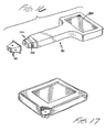
- Fig. 17 depicts an alternative embodiment of a meter adapted for use with the disposable of Fig. 11.
- Fig. 18 depicts the distal portion of yet another embodiment of a disposable 210 and meter 230.
- Distal section 232 mates with disposable 210.
- slots 234 are an alternative to groove 34 (or 134) for capturing indentations, such as 220, on the disposable.
- Fig. 19 is a side view of the embodiment of Fig. 18.
- a blood sample is picked up on the outward-facing surface of the membrane.
- Glucose in the sample interacts with a reagent in the membrane to cause a color change, which changes the reflectance of the inward-facing membrane surface.
- the light source in the meter illuminates the inward-facing membrane surface and measures the intensity of light reflected from that surface. Using the appropriate computation, the change in reflectance yields the glucose concentration in the sample.
- a variety of combinations of membrane and reagent compositions are known for photometric determinations of blood glucose concentration.
- a preferred membrane/reagent composition is a polyamide matrix incorporating an oxidase enzyme, a peroxidase, and a dye or dye couple.
- the oxidase enzyme is preferably glucose oxidase.
- the peroxidase is preferably horseradish peroxidase.
- a preferred dye couple is 3-methyl-2 benzothiazolinone hydrazone hydrochloride plus 3,3-dimethylaminobenzoic acid. Details of that membrane/reagent combination and variations on it appear in U.S. Pat. 5,304,468, issued April 19, 1994, to Phillips et al., incorporated herein by reference.
- Another preferred membrane/reagent composition is an anisotropic polysulfone membrane (available from Memtec America Corp., Timonium, MD) incorporating glucose oxidase, horseradish peroxidase, and the dye couple [3-methyl-2-benzothiazolinone hydrazone] N-sulfonyl benzenesulfonate monosodium combined with 8-anilino-1-naphthalene sulfonic acid ammonium. Details of that membrane/reagent combination and variations on it appear in U.S. Pat. Appl. Ser. No. 08/302,575, filed September 8, 1994, incorporated herein by reference.
Abstract
Description
Claims (7)
- A method for measuring a concentration of an analyte in a sample of a biological fluid comprising(a) providing a device that comprises a hollow frustum having open ends of unequal size, whose smaller end is substantially closed by a membrane that has(ii) a first surface for accepting the sample and(ii) a reagent for reacting with the analyte to cause, in a physically detectable parameter of the membrane, a change that can be measured and be related to the concentration of the analyte in the sample;(b) applying the sample to the first surface;(c) measuring the change in the parameter; and(d) determining the analyte concentration from the measurement of the parameter change.
- The method of daim 1 in which the device is provided on an end of an elongated meter, which both supports the device and measures the parameter change.
- The method of claim 2 in which the elongated meter has a frustum-shaped distal section for mating engagement with the device for making the measurement.
- The method of claim 3 in which providing the device on the end of the meter comprises removably engaging a peripheral groove on the distal section of the meter with indentations on a perimeter of the device, without a user directly contacting the device.
- The method of daim 1 in which the reagent reacts with the analyte to cause a color change, and the membrane parameter whose change is measured is a reflectance of a second surface, opposite to the first surface.
- The method of claim 5 in which the sample is whole blood and the analyte is blood glucose.
- The method of claim 1 further comprising the step of removing the device from the meter, without directly contacting the device.
Applications Claiming Priority (2)
| Application Number | Priority Date | Filing Date | Title |
|---|---|---|---|
| US694972 | 1996-08-09 | ||
| US08/694,972 US5753429A (en) | 1996-08-09 | 1996-08-09 | Analyte concentration measurement using a hollow frustum |
Publications (3)
| Publication Number | Publication Date |
|---|---|
| EP0823634A2 true EP0823634A2 (en) | 1998-02-11 |
| EP0823634A3 EP0823634A3 (en) | 2000-03-15 |
| EP0823634B1 EP0823634B1 (en) | 2004-02-25 |
Family
ID=24791046
Family Applications (1)
| Application Number | Title | Priority Date | Filing Date |
|---|---|---|---|
| EP97306038A Expired - Lifetime EP0823634B1 (en) | 1996-08-09 | 1997-08-08 | Analyte concentration measurement using a hollow frustum |
Country Status (21)
| Country | Link |
|---|---|
| US (1) | US5753429A (en) |
| EP (1) | EP0823634B1 (en) |
| JP (1) | JPH10132813A (en) |
| KR (1) | KR100562179B1 (en) |
| CN (1) | CN1125339C (en) |
| AR (1) | AR009047A1 (en) |
| AT (1) | ATE260465T1 (en) |
| AU (1) | AU712523B2 (en) |
| BR (1) | BR9704296A (en) |
| CA (1) | CA2212601A1 (en) |
| DE (1) | DE69727737T2 (en) |
| DK (1) | DK0823634T3 (en) |
| ES (1) | ES2215213T3 (en) |
| HK (1) | HK1004420A1 (en) |
| IL (1) | IL121482A (en) |
| MY (1) | MY116949A (en) |
| NO (1) | NO320168B1 (en) |
| PT (1) | PT823634E (en) |
| RU (1) | RU2201595C2 (en) |
| SG (1) | SG73465A1 (en) |
| TW (1) | TW355677B (en) |
Families Citing this family (80)
| Publication number | Priority date | Publication date | Assignee | Title |
|---|---|---|---|---|
| US6391005B1 (en) | 1998-03-30 | 2002-05-21 | Agilent Technologies, Inc. | Apparatus and method for penetration with shaft having a sensor for sensing penetration depth |
| JP3654786B2 (en) | 1999-02-08 | 2005-06-02 | テルモ株式会社 | Component measurement chip |
| US6458326B1 (en) | 1999-11-24 | 2002-10-01 | Home Diagnostics, Inc. | Protective test strip platform |
| US8641644B2 (en) | 2000-11-21 | 2014-02-04 | Sanofi-Aventis Deutschland Gmbh | Blood testing apparatus having a rotatable cartridge with multiple lancing elements and testing means |
| US6541266B2 (en) | 2001-02-28 | 2003-04-01 | Home Diagnostics, Inc. | Method for determining concentration of an analyte in a test strip |
| US6562625B2 (en) | 2001-02-28 | 2003-05-13 | Home Diagnostics, Inc. | Distinguishing test types through spectral analysis |
| US6525330B2 (en) | 2001-02-28 | 2003-02-25 | Home Diagnostics, Inc. | Method of strip insertion detection |
| ATE485766T1 (en) | 2001-06-12 | 2010-11-15 | Pelikan Technologies Inc | ELECTRICAL ACTUATING ELEMENT FOR A LANCET |
| US9795747B2 (en) | 2010-06-02 | 2017-10-24 | Sanofi-Aventis Deutschland Gmbh | Methods and apparatus for lancet actuation |
| US9226699B2 (en) | 2002-04-19 | 2016-01-05 | Sanofi-Aventis Deutschland Gmbh | Body fluid sampling module with a continuous compression tissue interface surface |
| US7749174B2 (en) | 2001-06-12 | 2010-07-06 | Pelikan Technologies, Inc. | Method and apparatus for lancet launching device intergrated onto a blood-sampling cartridge |
| DE60234598D1 (en) | 2001-06-12 | 2010-01-14 | Pelikan Technologies Inc | SELF-OPTIMIZING LANZET DEVICE WITH ADAPTANT FOR TEMPORAL FLUCTUATIONS OF SKIN PROPERTIES |
| US7981056B2 (en) | 2002-04-19 | 2011-07-19 | Pelikan Technologies, Inc. | Methods and apparatus for lancet actuation |
| US9427532B2 (en) | 2001-06-12 | 2016-08-30 | Sanofi-Aventis Deutschland Gmbh | Tissue penetration device |
| US7025774B2 (en) | 2001-06-12 | 2006-04-11 | Pelikan Technologies, Inc. | Tissue penetration device |
| US8337419B2 (en) | 2002-04-19 | 2012-12-25 | Sanofi-Aventis Deutschland Gmbh | Tissue penetration device |
| US6723500B2 (en) * | 2001-12-05 | 2004-04-20 | Lifescan, Inc. | Test strips having reaction zones and channels defined by a thermally transferred hydrophobic barrier |
| US6872358B2 (en) | 2002-01-16 | 2005-03-29 | Lifescan, Inc. | Test strip dispenser |
| US7901362B2 (en) | 2002-04-19 | 2011-03-08 | Pelikan Technologies, Inc. | Method and apparatus for penetrating tissue |
| US7892185B2 (en) | 2002-04-19 | 2011-02-22 | Pelikan Technologies, Inc. | Method and apparatus for body fluid sampling and analyte sensing |
| US8784335B2 (en) | 2002-04-19 | 2014-07-22 | Sanofi-Aventis Deutschland Gmbh | Body fluid sampling device with a capacitive sensor |
| US9248267B2 (en) | 2002-04-19 | 2016-02-02 | Sanofi-Aventis Deustchland Gmbh | Tissue penetration device |
| US9314194B2 (en) | 2002-04-19 | 2016-04-19 | Sanofi-Aventis Deutschland Gmbh | Tissue penetration device |
| US7909778B2 (en) | 2002-04-19 | 2011-03-22 | Pelikan Technologies, Inc. | Method and apparatus for penetrating tissue |
| US7547287B2 (en) | 2002-04-19 | 2009-06-16 | Pelikan Technologies, Inc. | Method and apparatus for penetrating tissue |
| US7175642B2 (en) | 2002-04-19 | 2007-02-13 | Pelikan Technologies, Inc. | Methods and apparatus for lancet actuation |
| US7674232B2 (en) | 2002-04-19 | 2010-03-09 | Pelikan Technologies, Inc. | Method and apparatus for penetrating tissue |
| US9795334B2 (en) | 2002-04-19 | 2017-10-24 | Sanofi-Aventis Deutschland Gmbh | Method and apparatus for penetrating tissue |
| US7226461B2 (en) | 2002-04-19 | 2007-06-05 | Pelikan Technologies, Inc. | Method and apparatus for a multi-use body fluid sampling device with sterility barrier release |
| US7892183B2 (en) | 2002-04-19 | 2011-02-22 | Pelikan Technologies, Inc. | Method and apparatus for body fluid sampling and analyte sensing |
| US8702624B2 (en) | 2006-09-29 | 2014-04-22 | Sanofi-Aventis Deutschland Gmbh | Analyte measurement device with a single shot actuator |
| US7331931B2 (en) | 2002-04-19 | 2008-02-19 | Pelikan Technologies, Inc. | Method and apparatus for penetrating tissue |
| US7297122B2 (en) | 2002-04-19 | 2007-11-20 | Pelikan Technologies, Inc. | Method and apparatus for penetrating tissue |
| US8221334B2 (en) | 2002-04-19 | 2012-07-17 | Sanofi-Aventis Deutschland Gmbh | Method and apparatus for penetrating tissue |
| US8267870B2 (en) | 2002-04-19 | 2012-09-18 | Sanofi-Aventis Deutschland Gmbh | Method and apparatus for body fluid sampling with hybrid actuation |
| US7229458B2 (en) | 2002-04-19 | 2007-06-12 | Pelikan Technologies, Inc. | Method and apparatus for penetrating tissue |
| US7232451B2 (en) | 2002-04-19 | 2007-06-19 | Pelikan Technologies, Inc. | Method and apparatus for penetrating tissue |
| US8579831B2 (en) | 2002-04-19 | 2013-11-12 | Sanofi-Aventis Deutschland Gmbh | Method and apparatus for penetrating tissue |
| US7976476B2 (en) | 2002-04-19 | 2011-07-12 | Pelikan Technologies, Inc. | Device and method for variable speed lancet |
| US7491178B2 (en) | 2002-04-19 | 2009-02-17 | Pelikan Technologies, Inc. | Method and apparatus for penetrating tissue |
| US8360992B2 (en) | 2002-04-19 | 2013-01-29 | Sanofi-Aventis Deutschland Gmbh | Method and apparatus for penetrating tissue |
| US7343188B2 (en) * | 2002-05-09 | 2008-03-11 | Lifescan, Inc. | Devices and methods for accessing and analyzing physiological fluid |
| US20030212344A1 (en) * | 2002-05-09 | 2003-11-13 | Vadim Yuzhakov | Physiological sample collection devices and methods of using the same |
| US20030223906A1 (en) * | 2002-06-03 | 2003-12-04 | Mcallister Devin | Test strip container system |
| US8574895B2 (en) | 2002-12-30 | 2013-11-05 | Sanofi-Aventis Deutschland Gmbh | Method and apparatus using optical techniques to measure analyte levels |
| EP1628567B1 (en) | 2003-05-30 | 2010-08-04 | Pelikan Technologies Inc. | Method and apparatus for fluid injection |
| DK1633235T3 (en) | 2003-06-06 | 2014-08-18 | Sanofi Aventis Deutschland | Apparatus for sampling body fluid and detecting analyte |
| WO2006001797A1 (en) | 2004-06-14 | 2006-01-05 | Pelikan Technologies, Inc. | Low pain penetrating |
| US8282576B2 (en) | 2003-09-29 | 2012-10-09 | Sanofi-Aventis Deutschland Gmbh | Method and apparatus for an improved sample capture device |
| EP1680014A4 (en) | 2003-10-14 | 2009-01-21 | Pelikan Technologies Inc | Method and apparatus for a variable user interface |
| US7822454B1 (en) | 2005-01-03 | 2010-10-26 | Pelikan Technologies, Inc. | Fluid sampling device with improved analyte detecting member configuration |
| EP1706026B1 (en) | 2003-12-31 | 2017-03-01 | Sanofi-Aventis Deutschland GmbH | Method and apparatus for improving fluidic flow and sample capture |
| US8828203B2 (en) | 2004-05-20 | 2014-09-09 | Sanofi-Aventis Deutschland Gmbh | Printable hydrogels for biosensors |
| EP1765194A4 (en) | 2004-06-03 | 2010-09-29 | Pelikan Technologies Inc | Method and apparatus for a fluid sampling device |
| US9775553B2 (en) | 2004-06-03 | 2017-10-03 | Sanofi-Aventis Deutschland Gmbh | Method and apparatus for a fluid sampling device |
| US8652831B2 (en) | 2004-12-30 | 2014-02-18 | Sanofi-Aventis Deutschland Gmbh | Method and apparatus for analyte measurement test time |
| KR101321296B1 (en) * | 2005-07-20 | 2013-10-28 | 바이엘 헬스케어 엘엘씨 | Gated amperometry temperature determination |
| JP4909987B2 (en) * | 2006-03-22 | 2012-04-04 | パナソニック株式会社 | Blood test equipment |
| JP4871083B2 (en) * | 2006-09-27 | 2012-02-08 | テルモ株式会社 | Body fluid collection unit |
| JPWO2008136472A1 (en) * | 2007-04-29 | 2010-07-29 | アークレイ株式会社 | Analysis system |
| CA2708038A1 (en) * | 2007-12-10 | 2009-09-03 | Bayer Healthcare Llc | Slope-based compensation |
| US8052166B2 (en) * | 2008-03-10 | 2011-11-08 | Hendrickson Usa, Llc. | Tie-plate and frame hanger of a suspension assembly |
| US8152195B2 (en) * | 2008-03-10 | 2012-04-10 | Hendrickson Usa, Llc | Modular suspension system and components thereof |
| US8302988B2 (en) | 2008-03-10 | 2012-11-06 | Hendrickson Usa, L.L.C. | Suspension assembly with tie-plate |
| US7926836B2 (en) | 2008-03-10 | 2011-04-19 | Hendrickson Usa, Llc. | Elastomeric spring vehicle suspension |
| WO2009126900A1 (en) | 2008-04-11 | 2009-10-15 | Pelikan Technologies, Inc. | Method and apparatus for analyte detecting device |
| ES2352581T3 (en) * | 2008-06-02 | 2011-02-21 | Boehringer Ingelheim Microparts Gmbh | STRUCTURE OF MICROFLUIDIC SHEET FOR DOSAGE OF LIQUIDS. |
| US9375169B2 (en) | 2009-01-30 | 2016-06-28 | Sanofi-Aventis Deutschland Gmbh | Cam drive for managing disposable penetrating member actions with a single motor and motor and control system |
| USD633011S1 (en) | 2009-06-02 | 2011-02-22 | Hendrickson Usa, L.L.C. | Suspension assembly |
| US8965476B2 (en) | 2010-04-16 | 2015-02-24 | Sanofi-Aventis Deutschland Gmbh | Tissue penetration device |
| USD672286S1 (en) | 2010-09-05 | 2012-12-11 | Hendrickson Usa, L.L.C. | Suspension assembly |
| CA2901215C (en) | 2011-07-08 | 2016-09-13 | Hendrickson Usa, L.L.C. | Vehicle suspension and improved method of assembly |
| US8262112B1 (en) | 2011-07-08 | 2012-09-11 | Hendrickson Usa, L.L.C. | Vehicle suspension and improved method of assembly |
| US9004512B2 (en) | 2011-07-08 | 2015-04-14 | Hendrickson Usa, L.L.C. | Shear spring useful for vehicle suspension |
| USD700113S1 (en) | 2012-07-06 | 2014-02-25 | Hendrickson Usa, L.L.C. | Suspension assembly |
| USD700112S1 (en) | 2012-07-06 | 2014-02-25 | Hendrickson Usa, L.L.C. | Progressive rate spring for a suspension |
| US9085212B2 (en) | 2013-03-15 | 2015-07-21 | Hendrickson Usa, L.L.C. | Vehicle suspension |
| US9150071B2 (en) | 2013-07-25 | 2015-10-06 | Hendrickson Usa, L.L.C. | Frame hanger for vehicle suspension |
| EP2835639B1 (en) * | 2013-08-09 | 2020-01-01 | Roche Diabetes Care GmbH | Test tape device and operating method |
| CA2950166C (en) | 2014-07-25 | 2023-08-01 | Becton, Dickinson And Company | Analyte test strip assays, and test strips and kits for use in practicing the same |
Citations (6)
| Publication number | Priority date | Publication date | Assignee | Title |
|---|---|---|---|---|
| US3992158A (en) * | 1973-08-16 | 1976-11-16 | Eastman Kodak Company | Integral analytical element |
| EP0585744A1 (en) * | 1992-08-21 | 1994-03-09 | Boehringer Mannheim Gmbh | Light transmitting analytical element for determination of an analyte |
| EP0588564A1 (en) * | 1992-09-18 | 1994-03-23 | AMERSHAM INTERNATIONAL plc | Device and method for affinity separation |
| EP0637749A2 (en) * | 1993-08-05 | 1995-02-08 | Roche Diagnostics GmbH | System for analysing liquid samples |
| WO1996030752A1 (en) * | 1995-03-16 | 1996-10-03 | Health Craft International, Inc. | Apparatus for monitoring glucose level |
| WO1997026539A1 (en) * | 1996-01-16 | 1997-07-24 | Beckman Instruments, Inc. | Analytical biochemistry system with robotically carried bioarray |
Family Cites Families (9)
| Publication number | Priority date | Publication date | Assignee | Title |
|---|---|---|---|---|
| FR2287941A1 (en) * | 1974-10-15 | 1976-05-14 | Marteau D Autry Eric | DEVICE FOR EJECTING THE REMOVABLE TIP OF A PIPETTE |
| US4627445A (en) * | 1985-04-08 | 1986-12-09 | Garid, Inc. | Glucose medical monitoring system |
| US4935346A (en) * | 1986-08-13 | 1990-06-19 | Lifescan, Inc. | Minimum procedure system for the determination of analytes |
| US4874691A (en) * | 1987-10-16 | 1989-10-17 | Quadra Logic Technologies Inc. | Membrane-supported immunoassays |
| US4952373A (en) * | 1989-04-21 | 1990-08-28 | Biotrack, Inc. | Liquid shield for cartridge |
| US5100620A (en) * | 1989-05-15 | 1992-03-31 | Miles, Inc. | Capillary tube/gap reagent format |
| US5234813A (en) * | 1989-05-17 | 1993-08-10 | Actimed Laboratories, Inc. | Method and device for metering of fluid samples and detection of analytes therein |
| IE75720B1 (en) * | 1990-10-08 | 1997-09-24 | Akzo Nv | Device for performing a rapid single manual assay |
| US5563031A (en) * | 1994-09-08 | 1996-10-08 | Lifescan, Inc. | Highly stable oxidative coupling dye for spectrophotometric determination of analytes |
-
1996
- 1996-08-09 US US08/694,972 patent/US5753429A/en not_active Expired - Lifetime
-
1997
- 1997-08-06 CA CA002212601A patent/CA2212601A1/en not_active Abandoned
- 1997-08-06 IL IL12148297A patent/IL121482A/en not_active IP Right Cessation
- 1997-08-07 SG SG1997002814A patent/SG73465A1/en unknown
- 1997-08-07 AU AU33208/97A patent/AU712523B2/en not_active Expired
- 1997-08-08 JP JP9225611A patent/JPH10132813A/en active Pending
- 1997-08-08 PT PT97306038T patent/PT823634E/en unknown
- 1997-08-08 DK DK97306038T patent/DK0823634T3/en active
- 1997-08-08 AT AT97306038T patent/ATE260465T1/en active
- 1997-08-08 KR KR1019970038354A patent/KR100562179B1/en not_active IP Right Cessation
- 1997-08-08 NO NO19973662A patent/NO320168B1/en not_active IP Right Cessation
- 1997-08-08 ES ES97306038T patent/ES2215213T3/en not_active Expired - Lifetime
- 1997-08-08 MY MYPI97003628A patent/MY116949A/en unknown
- 1997-08-08 DE DE69727737T patent/DE69727737T2/en not_active Expired - Lifetime
- 1997-08-08 EP EP97306038A patent/EP0823634B1/en not_active Expired - Lifetime
- 1997-08-08 RU RU97114130/14A patent/RU2201595C2/en active
- 1997-08-08 BR BR9704296A patent/BR9704296A/en not_active Application Discontinuation
- 1997-08-09 CN CN97119269A patent/CN1125339C/en not_active Expired - Lifetime
- 1997-08-11 AR ARP970103640A patent/AR009047A1/en unknown
- 1997-08-27 TW TW086111563A patent/TW355677B/en not_active IP Right Cessation
-
1998
- 1998-05-01 HK HK98103744A patent/HK1004420A1/en not_active IP Right Cessation
Patent Citations (6)
| Publication number | Priority date | Publication date | Assignee | Title |
|---|---|---|---|---|
| US3992158A (en) * | 1973-08-16 | 1976-11-16 | Eastman Kodak Company | Integral analytical element |
| EP0585744A1 (en) * | 1992-08-21 | 1994-03-09 | Boehringer Mannheim Gmbh | Light transmitting analytical element for determination of an analyte |
| EP0588564A1 (en) * | 1992-09-18 | 1994-03-23 | AMERSHAM INTERNATIONAL plc | Device and method for affinity separation |
| EP0637749A2 (en) * | 1993-08-05 | 1995-02-08 | Roche Diagnostics GmbH | System for analysing liquid samples |
| WO1996030752A1 (en) * | 1995-03-16 | 1996-10-03 | Health Craft International, Inc. | Apparatus for monitoring glucose level |
| WO1997026539A1 (en) * | 1996-01-16 | 1997-07-24 | Beckman Instruments, Inc. | Analytical biochemistry system with robotically carried bioarray |
Also Published As
| Publication number | Publication date |
|---|---|
| NO320168B1 (en) | 2005-11-07 |
| CA2212601A1 (en) | 1998-02-09 |
| CN1125339C (en) | 2003-10-22 |
| PT823634E (en) | 2004-07-30 |
| CN1178904A (en) | 1998-04-15 |
| IL121482A0 (en) | 1998-02-08 |
| HK1004420A1 (en) | 1998-11-27 |
| IL121482A (en) | 2000-08-31 |
| DE69727737D1 (en) | 2004-04-01 |
| JPH10132813A (en) | 1998-05-22 |
| EP0823634B1 (en) | 2004-02-25 |
| AU3320897A (en) | 1998-02-12 |
| NO973662D0 (en) | 1997-08-08 |
| AR009047A1 (en) | 2000-03-08 |
| ES2215213T3 (en) | 2004-10-01 |
| SG73465A1 (en) | 2000-06-20 |
| AU712523B2 (en) | 1999-11-11 |
| ATE260465T1 (en) | 2004-03-15 |
| KR19980018609A (en) | 1998-06-05 |
| TW355677B (en) | 1999-04-11 |
| DE69727737T2 (en) | 2009-09-24 |
| BR9704296A (en) | 1999-04-06 |
| RU2201595C2 (en) | 2003-03-27 |
| US5753429A (en) | 1998-05-19 |
| KR100562179B1 (en) | 2006-08-31 |
| EP0823634A3 (en) | 2000-03-15 |
| MY116949A (en) | 2004-04-30 |
| DK0823634T3 (en) | 2004-06-01 |
| MX9706103A (en) | 1998-05-31 |
| NO973662L (en) | 1998-02-10 |
Similar Documents
| Publication | Publication Date | Title |
|---|---|---|
| US5736103A (en) | Remote-dosing analyte concentration meter | |
| EP0823634B1 (en) | Analyte concentration measurement using a hollow frustum | |
| US5846486A (en) | Hollow frustum reagent test device | |
| US6099802A (en) | Hollow frustum reagent test device | |
| AU688979B2 (en) | Analyte detection strip with orientation index | |
| US20120165626A1 (en) | Devices, methods, and kits for determining analyte concentrations | |
| MXPA97006102A (en) | Hollow troncoconic device for pru reagents | |
| MXPA97006103A (en) | Measurement of analytic concentration through the use of a hu troncoconic device | |
| MXPA97006104A (en) | Concentration meter of analytics by remote |
Legal Events
| Date | Code | Title | Description |
|---|---|---|---|
| PUAI | Public reference made under article 153(3) epc to a published international application that has entered the european phase |
Free format text: ORIGINAL CODE: 0009012 |
|
| AK | Designated contracting states |
Kind code of ref document: A2 Designated state(s): AT BE CH DE DK ES FI FR GB GR IT LI LU NL PT SE |
|
| PUAL | Search report despatched |
Free format text: ORIGINAL CODE: 0009013 |
|
| AK | Designated contracting states |
Kind code of ref document: A3 Designated state(s): AT BE CH DE DK ES FI FR GB GR IE IT LI LU MC NL PT SE |
|
| 17P | Request for examination filed |
Effective date: 20000821 |
|
| AKX | Designation fees paid |
Free format text: AT BE CH DE DK ES FI FR GB GR IT LI LU NL PT SE |
|
| 17Q | First examination report despatched |
Effective date: 20020923 |
|
| GRAP | Despatch of communication of intention to grant a patent |
Free format text: ORIGINAL CODE: EPIDOSNIGR1 |
|
| GRAS | Grant fee paid |
Free format text: ORIGINAL CODE: EPIDOSNIGR3 |
|
| GRAA | (expected) grant |
Free format text: ORIGINAL CODE: 0009210 |
|
| AK | Designated contracting states |
Kind code of ref document: B1 Designated state(s): AT BE CH DE DK ES FI FR GB GR IT LI LU NL PT SE |
|
| REG | Reference to a national code |
Ref country code: GB Ref legal event code: FG4D |
|
| REG | Reference to a national code |
Ref country code: CH Ref legal event code: EP |
|
| REF | Corresponds to: |
Ref document number: 69727737 Country of ref document: DE Date of ref document: 20040401 Kind code of ref document: P |
|
| REG | Reference to a national code |
Ref country code: GR Ref legal event code: EP Ref document number: 20040401400 Country of ref document: GR |
|
| REG | Reference to a national code |
Ref country code: DK Ref legal event code: T3 |
|
| REG | Reference to a national code |
Ref country code: SE Ref legal event code: TRGR Ref country code: CH Ref legal event code: NV Representative=s name: E. BLUM & CO. PATENTANWAELTE |
|
| REG | Reference to a national code |
Ref country code: PT Ref legal event code: SC4A Free format text: AVAILABILITY OF NATIONAL TRANSLATION Effective date: 20040521 |
|
| REG | Reference to a national code |
Ref country code: HK Ref legal event code: GR Ref document number: 1004420 Country of ref document: HK |
|
| REG | Reference to a national code |
Ref country code: ES Ref legal event code: FG2A Ref document number: 2215213 Country of ref document: ES Kind code of ref document: T3 |
|
| ET | Fr: translation filed | ||
| PLBE | No opposition filed within time limit |
Free format text: ORIGINAL CODE: 0009261 |
|
| STAA | Information on the status of an ep patent application or granted ep patent |
Free format text: STATUS: NO OPPOSITION FILED WITHIN TIME LIMIT |
|
| 26N | No opposition filed |
Effective date: 20041126 |
|
| REG | Reference to a national code |
Ref country code: CH Ref legal event code: PFA Owner name: LIFESCAN, INC. Free format text: LIFESCAN, INC.#1000 GIBRALTAR DRIVE#MILPITAS, CALIFORNIA 95035-6312 (US) -TRANSFER TO- LIFESCAN, INC.#1000 GIBRALTAR DRIVE#MILPITAS, CALIFORNIA 95035-6312 (US) |
|
| REG | Reference to a national code |
Ref country code: FR Ref legal event code: PLFP Year of fee payment: 20 |
|
| PGFP | Annual fee paid to national office [announced via postgrant information from national office to epo] |
Ref country code: LU Payment date: 20160801 Year of fee payment: 20 Ref country code: NL Payment date: 20160810 Year of fee payment: 20 |
|
| PGFP | Annual fee paid to national office [announced via postgrant information from national office to epo] |
Ref country code: IT Payment date: 20160822 Year of fee payment: 20 Ref country code: DE Payment date: 20160802 Year of fee payment: 20 Ref country code: GB Payment date: 20160803 Year of fee payment: 20 Ref country code: FI Payment date: 20160809 Year of fee payment: 20 Ref country code: DK Payment date: 20160810 Year of fee payment: 20 Ref country code: CH Payment date: 20160812 Year of fee payment: 20 |
|
| PGFP | Annual fee paid to national office [announced via postgrant information from national office to epo] |
Ref country code: GR Payment date: 20160722 Year of fee payment: 20 Ref country code: SE Payment date: 20160811 Year of fee payment: 20 Ref country code: AT Payment date: 20160725 Year of fee payment: 20 Ref country code: PT Payment date: 20160804 Year of fee payment: 20 Ref country code: FR Payment date: 20160712 Year of fee payment: 20 |
|
| PGFP | Annual fee paid to national office [announced via postgrant information from national office to epo] |
Ref country code: BE Payment date: 20160713 Year of fee payment: 20 Ref country code: ES Payment date: 20160712 Year of fee payment: 20 |
|
| REG | Reference to a national code |
Ref country code: DE Ref legal event code: R071 Ref document number: 69727737 Country of ref document: DE |
|
| REG | Reference to a national code |
Ref country code: NL Ref legal event code: MK Effective date: 20170807 |
|
| REG | Reference to a national code |
Ref country code: DK Ref legal event code: EUP Effective date: 20170808 |
|
| REG | Reference to a national code |
Ref country code: CH Ref legal event code: PL |
|
| REG | Reference to a national code |
Ref country code: GB Ref legal event code: PE20 Expiry date: 20170807 |
|
| REG | Reference to a national code |
Ref country code: AT Ref legal event code: MK07 Ref document number: 260465 Country of ref document: AT Kind code of ref document: T Effective date: 20170808 |
|
| REG | Reference to a national code |
Ref country code: SE Ref legal event code: EUG |
|
| REG | Reference to a national code |
Ref country code: BE Ref legal event code: MK Effective date: 20170808 |
|
| PG25 | Lapsed in a contracting state [announced via postgrant information from national office to epo] |
Ref country code: GB Free format text: LAPSE BECAUSE OF EXPIRATION OF PROTECTION Effective date: 20170807 Ref country code: PT Free format text: LAPSE BECAUSE OF EXPIRATION OF PROTECTION Effective date: 20170817 |
|
| REG | Reference to a national code |
Ref country code: ES Ref legal event code: FD2A Effective date: 20180508 |
|
| PG25 | Lapsed in a contracting state [announced via postgrant information from national office to epo] |
Ref country code: ES Free format text: LAPSE BECAUSE OF EXPIRATION OF PROTECTION Effective date: 20170809 |