EP0831004A2 - Rail guided vehicle - Google Patents
Rail guided vehicle Download PDFInfo
- Publication number
- EP0831004A2 EP0831004A2 EP97890183A EP97890183A EP0831004A2 EP 0831004 A2 EP0831004 A2 EP 0831004A2 EP 97890183 A EP97890183 A EP 97890183A EP 97890183 A EP97890183 A EP 97890183A EP 0831004 A2 EP0831004 A2 EP 0831004A2
- Authority
- EP
- European Patent Office
- Prior art keywords
- sensor
- rail
- guided vehicle
- computer
- drive
- Prior art date
- Legal status (The legal status is an assumption and is not a legal conclusion. Google has not performed a legal analysis and makes no representation as to the accuracy of the status listed.)
- Withdrawn
Links
Images

Classifications
-
- B—PERFORMING OPERATIONS; TRANSPORTING
- B61—RAILWAYS
- B61F—RAIL VEHICLE SUSPENSIONS, e.g. UNDERFRAMES, BOGIES OR ARRANGEMENTS OF WHEEL AXLES; RAIL VEHICLES FOR USE ON TRACKS OF DIFFERENT WIDTH; PREVENTING DERAILING OF RAIL VEHICLES; WHEEL GUARDS, OBSTRUCTION REMOVERS OR THE LIKE FOR RAIL VEHICLES
- B61F5/00—Constructional details of bogies; Connections between bogies and vehicle underframes; Arrangements or devices for adjusting or allowing self-adjustment of wheel axles or bogies when rounding curves
- B61F5/02—Arrangements permitting limited transverse relative movements between vehicle underframe or bolster and bogie; Connections between underframes and bogies
- B61F5/22—Guiding of the vehicle underframes with respect to the bogies
-
- B—PERFORMING OPERATIONS; TRANSPORTING
- B60—VEHICLES IN GENERAL
- B60L—PROPULSION OF ELECTRICALLY-PROPELLED VEHICLES; SUPPLYING ELECTRIC POWER FOR AUXILIARY EQUIPMENT OF ELECTRICALLY-PROPELLED VEHICLES; ELECTRODYNAMIC BRAKE SYSTEMS FOR VEHICLES IN GENERAL; MAGNETIC SUSPENSION OR LEVITATION FOR VEHICLES; MONITORING OPERATING VARIABLES OF ELECTRICALLY-PROPELLED VEHICLES; ELECTRIC SAFETY DEVICES FOR ELECTRICALLY-PROPELLED VEHICLES
- B60L2200/00—Type of vehicles
- B60L2200/26—Rail vehicles
Definitions
- the invention has a rail-guided vehicle, e.g. B. traction vehicle, Waggon, to the object in which a component is transverse is movable to the direction of travel of the vehicle.
- a rail-guided vehicle e.g. B. traction vehicle, Waggon
- Rail-guided vehicles be it rail vehicles or for example magnetic levitation trains u.
- the like will be forever higher speeds, such as significantly above 200 km per hour.
- a corresponding expansion of the route such as banked bends also constructive measures for the vehicles, especially that rolling stock, required. So an aerodynamic cheap training of the vehicles carried out for a corresponding Storage care to be taken u.
- New routes are tried, the desire to have one if possible to achieve rectilinear guidance of the same, as far as possible consider.
- For existing routes and especially for mountainous terrain are the most straightforward guidance of Stretch limits set so that to get higher speeds to reach the trains in curves, not a cant alone is sufficient.
- So-called wagon body inclination systems are used for this purpose have been developed either centrally for one Train or one for each wagon or drive unit of the train Have tilting device.
- the car body is in the The interior of the curve is inclined, which means that driving comfort remains the same of the passengers a higher speed in the curve can be driven.
- a locomotive can also be a Have car body tilt system.
- Speed the possibility of one by centrifugal force counteracting the inclination of the body of the motor vehicle.
- At the body of the locomotive there is one Line arranged with overhead contact line of the pantographs, whereby through the tilting movements, which are speed-dependent, there is a risk that the current collector is no longer in contact with the overhead line. That means top speeds given.
- lateral acceleration forces to avoid under- or overcompensation by the Need to cause.
- the lateral acceleration forces on the one hand recorded as precisely as possible and on the other hand can also be fed to an exact processing.
- the simplest system has a piezoelectric one Circuit on, wherein the output from the piezo crystal Stress is proportional to the forces that occur.
- Such a thing Measuring system enables easy conversion from Forces in electrical quantities, however, are highly sensitive System, so that by natural vibrations of the car body, like they can occur, for example, by rolling it, Disruptions are caused that are exact and timely Control of the transverse movement significantly more difficult.
- Another system is that in the chassis gimbal-mounted gyro is provided.
- the gyroscope endeavors to maintain its plane of rotation. Act Forces on a gyroscope result in movement, namely Deflection of the gyro by 90 ° to the direction of action of the forces, a. Additional forces also occur here, for example with Piezo crystals can be determined.
- This system is too it is peculiar that there is a very high sensitivity, one effective control, in particular regulation of the transverse movement or the pivoting movement of components.
- Laser gyroscopes are also known, which are used in ships, submarines, Airplanes and missiles replace the conventional gyroscope.
- the principle of operation of a laser gyroscope essentially exists in that two laser beams in a triangle, which over Deflecting mirror is formed, run in opposite directions to each other. Becomes the arrangement, for example rotated to the left, requires the left rotating laser beam slightly longer for an entire Orbiting as the right-rotating laser beam. That difference can be determined from the wavefront. It's here particularly sensitive measuring system.
- the deflecting mirror glass fiber spools can also be used, whereby using certain laser diodes from a so-called Fiber gyroscope is spoken.
- Such systems are suitable on the one hand speeds and on the other hand changes of location to eat. Lateral acceleration forces are generated with such a System not measured. It can only be a change of direction or change in speed can be measured.
- GB-2 079 701-A becomes a magnetic levitation train wagon known with car body control.
- the car body lies hiebei over rollers, their axes in the direction of travel of the train are oriented on the chassis. These roles are on one own carrier provided, on the center of which a piston rod is articulated, whereas the corresponding cylinder on the chassis is articulated.
- This cylinder is operated hydraulically.
- either a pump for the Hydraulic fluid or just a valve with a Pressure source is connected to be controlled.
- filters and amplifiers To control individual circuits with detectors, filters and amplifiers provided, both lateral accelerations and Vertical accelerations measured and in electrical quantities are converted, which are used directly for regulation will. Filters and, if necessary, are used to smooth the values integration over time.
- Filters and, if necessary, are used to smooth the values integration over time.
- the present invention has set itself the goal of being a rail-guided Vehicle with a chassis and one across Driving direction to create moving component that allows that Cross movements or swivel movements in rapid succession Perform the lateral acceleration forces, whereby on the one hand, the response times of the sensor should be very short should and on the other hand superimposed vibrations not or only influence the measured variables slightly. Furthermore, the possibility should exist, a link to other parameters enable.
- Another object of the present invention is to create a rail-guided vehicle that is as simple as possible and has a high level of operational reliability having. Furthermore, the sensor should be easy to install and only have a small footprint.
- the present invention is based on a prior art, as given by GB-A-2 079 701.
- the rail-guided vehicle according to the invention for. B. traction vehicle, Waggon, with a chassis, in particular bogie and at least one other component, e.g. B. car body, pantograph, which, based on the chassis, via a Drive can be moved transversely to the direction of travel of the vehicle, in particular is pivotable, the drive via a Sensor which can be influenced via lateral acceleration forces, can be operated, consists essentially in that the sensor with a capacitor is constructed, which is at least one relative to a movable component fixed capacitor plate and at least the one that can be moved by the transverse acceleration forces Has component, and in particular via an analog-digital converter, preferably with a computer, possibly with a time standard, over which the drive controlled, in particular regulated.
- a chassis in particular bogie and at least one other component, e.g. B. car body, pantograph, which, based on the chassis, via a Drive can be moved transversely to the direction of travel of the vehicle, in particular is pivotable,
- a capacitor is used as a sensor for the lateral acceleration forces used so can already when determining the capacity of the capacitor, which has a component that is different from the Lateral acceleration forces can be applied, a smoothing through the inertia of the moving component as well quick response can be achieved.
- the sensor in particular connected to a computer via an analog-digital converter, This means that additional parameters can be used to control the drive be taken into account particularly easily.
- capacitors with a moving component is known for static monitoring of structures, Machine beds, cranes, antenna masts and the like Like. Perform.
- the sensor is constructed with at least two capacitors, then can with the appropriate switching of the same vibrations can be compensated particularly easily because one of the code capacitors serves to deliver a reference voltage, and the other Capacitor is the measuring capacitor, so that a perfect Compensation of the vibrations that overlap the lateral forces, can be reached.
- a wagon is shown in a schematic representation.
- the Bogie 1 has wheels 2 with an axis 3, which over Coil springs 4 carries a bearing part 5, in which a Rotating part 6 is mounted on the pin 7.
- the rotating part 6 has Rollers 8, on which a support body 9 via partially cylindrical Surfaces 10 rests.
- the car body 11 can with the support body 9 be directly connected or, as in the present case, be resiliently connected via additional spring elements 12.
- a hydraulically actuated cylinder-piston unit that on the one hand on the support body 9 and on the other hand on Rotating part 6 is articulated, the support body 9 and thus the Car body 11 inclined to the horizontal in both directions will.
- a sensor 14 On the bogie 1 is a sensor 14 and on and in Car body 1 1 arranged a sensor 15, via which the Lateral acceleration forces can be absorbed via which, as described below, actuates the drive 13 is so that the support body 9 along its part-cylindrical Surfaces 10 can be moved on the rollers 8 of the rotary member 6.
- Fig. 2 is a Stromabnchmer 16 on the roof 17 one Motor vehicle shown.
- the pantograph 16 is along Guides 18 parallel to the roof 17 from a central position, in which of the pantographs is shown, via the drive 13, which via a compressed air cylinder-piston unit is formed in the two end positions left and right movable from the center position shown.
- the pantograph 16 has a pallet 19 which receives the current from the contact wire 20th decreases.
- FIG. 3 shows a current collector 16 which has a pallet 19 has, which is displaceable transversely to the contact wire 20.
- the Drives 13, u. between cylinder-piston units operated with compressed air are both on the pantograph 16 and on the Pallet 19 articulated.
- On the roof 17 of the locomotive can also be formed by a locomotive, for example, are signalers 21 arranged. Through this signal generator 21, which are formed by a photocell with a light source the respective end position of the pallet, referred to the left or right of of the middle position shown.
- On the pallet itself is a ray of light when it is in the end position reflecting surface 22 in the beam path of the signal generator arranged, which one at the respective end position of the pallet high reflection of the signal generator 21 on the Glass fiber conductor 33, which is fixed in position on the current collector 16, emitted light causes so that in the signal generator 21st provided photocell a signal, for example on a Calculator that can pass on, left end position or right end position reached.
- the position of the pallet or the pantograph can be determined also done via the drive itself. Is the drive through a Cylinder-piston unit is formed, so the cylinder can Have windows, to which a fiber optic cable from one Photodiode with light source is directed. The piston can go along of its surface, which is led past the window, with areas have different reflectivities. Through the different intensity of light entering the photodiode arrives, can then on the exact position of the piston in the cylinder Conclusion can be held. Every position of the piston in the cylinder however corresponds to a certain position of the pallet.
- a sensor 23 is shown, the one Has housing 24, in which fixed capacitor plates 25 and as a movable component 26 a liquid, u. between Cyclohexane, arranged with a dielectric constant of 2.0 is.
- the capacitor plates 25 are in a row one behind the other and spaced apart and plunge into the Liquid that forms the movable component 26.
- the Capacitor plates 25 are transverse, in particular normal, to Direction of travel of the rail-guided vehicle arranged. When driving along a straight route the liquid level 27 is oriented, as in FIG. 4a depicted on gravity.
- Capacitor plates such as 7, can be provided, which about an axis 32 in Direction of travel are rotatably mounted so that by loading of centrifugal forces the focus of the moving Capacitor plates 26 is moved towards the outside of the curve. This also changes the capacitance of the capacitor the area in which the fixed capacitor plates 25 and the movable capacitor plates each other cover, is changed.
- FIG. 5 shows a further sensor 23, which as so-called tube condenser is formed.
- the fixed Capacitor plates 25 are through concentrically arranged tubes educated.
- a guide 28 is arranged in the middle of these which the movable component 26, which also by concentrically arranged tubular capacitor plates are formed is that against the force of the spring 29 through that by the centrifugal force actable weight 30 more or less strongly between the fixed tubular capacitor plates 25 inserted will.
- the movable component 26 is the Force overcome the spring 29 accordingly and the movable Component 26 between the fixed capacitor plates 25 immerse and change the capacity.
- the fixed Component is formed by a capacitor plate 25 by a guide 28 is arranged electrically insulated.
- annular capacitor plates are spaced from one another arranged as a movable component 26 by electrically insulating elastically deformable ring elements 31 from each other are separated.
- a weight 30 arranged, which when subjected to centrifugal forces elastically deformable ring elements deformed so that the The distance between the capacitor plates is smaller, with what a change in the capacitance of the capacitor occurs.
- the guide transverse to the direction of travel the rail-guided vehicle is arranged, a measurement of the centrifugal forces in both directions across Direction of travel.
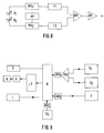
- FIG. 8 shows an electrical block diagram of a sensor, two capacitors K 1 and K 2 being provided, which have a capacitance that can be changed by centrifugal forces.
- the control with current takes place via the astable multivibrator AV, which controls and synchronizes the monostable multivibrators MV 1 and MV 2 , whereby the two monostable multivibrators simultaneously output a voltage level to the capacitors K 1 and K 2 .
- the capacitors K 1 and K 2 are charged via a resistor, not shown.
- the voltages of the capacitors are compared with a voltage standard.
- the resulting pulse-modulated signal which is proportional to the capacitance of the capacitor, passes through filters F 1 and F 2 , in which the high-frequency components of the current, which are due to vibrations, in particular natural frequencies, of the rail-bound vehicle or its components are filtered out will.
- the current then passes into the differential amplifier DV 1 , since the capacitors are also used to suppress interference.
- the current emerging from the differential amplifier DV 1 is amplified in the output amplifier AV and is then fed to the computer, possibly via an analog-digital converter.
- the capacitance of the capacitors K 1 and K 2 is between n farads and p farads.
- the sensor S 1 corresponds to the sensor 15 according to FIG. 1, which is attached to the car body, whereas the sensor S 2 corresponds to the sensor 14, which is provided on the bogie.
- the analog values of the sensors go into the differential amplifier DV 2 , so that the signal coming from the differential amplifier compensates for the inclination of the bogie transverse to the direction of travel and the total inclination of the car body and exposure to centrifugal forces, measured in S 1 .
- the value then reaches the computer R via the analog-digital converter AD 1.
- the sensor T To compensate for the temperature dependence of both the signals from the sensors S 1 and S 2 and the temperature dependence of the amplifier, the sensor T, u.
- thermocouple the temperature is measured and the value is entered into the computer via the analog-digital converter AD 2 , so that, based on a function entered into the computer, in which the temperature is the variable, the respective value of the lateral acceleration forces is determined or the drive A can be actuated as required.
- the speed can be entered into the computer via the sensor S 3 via the analog-digital converter AD 3 .
- the speed is decisive for how quickly the pantograph as well as the pallet and the body are to be moved or swiveled transversely to the direction of travel. At low speeds there is also a risk that the pantograph will be moved in the wrong direction. However, this process can be determined by the end position detection and corrected immediately afterwards.
- this Drive A can also be an electric motor, which has a pinion the arrangement of the components on a rack changes be.
- L can be used, for example, to reach the end position of the Pantograph of the pallet or the car body Computers are reported, with the further possibility of also certain intermediate layers of these components to the computer Report. It is only necessary that appropriate sensors be provided for the respective layers. Corresponds to the current situation of the component not the target position, can be done via the computer control again. Also, if in the computer Timer, e.g. B.
- quartz crystal is provided as the time standard, the Time which was required for the movement can be determined and e.g. B. a warning signal is switched on when a specification is exceeded, the speed is reduced or the pantograph subtracted from.
- the calculator can be used with a Recorder S are provided, each of the current data records.
- the program for the calculator is as follows:
- the program is basically structured so that none Input values can be output at an output, but always the output values depending on certain events be changed, d. that is, there is data encapsulation.
- the Analog values read in via a 10 bit analog-digital converter.
- the read values are then linked mathematically, with what other output values are generated.
- the variables, u. between computer variables, for the storage space in the computer (Placeholder in memory indicates length and type of variable type) To be defined. Then there is a generation of the domestic and Outputs of the inputs and outputs, the initialization of the peripheral blocks, u.
- An interrupt program is also dependent on the time provided, with the time registers required times for a certain movement checked and if necessary a shutdown takes place, for example, the pantograph is removed from the conductor is, with previously a main switch for the power supply to Interruption of the current flow is actuated. So can for example a maximum speed of rolling Materials are prescribed when minimum times for the Pantograph or pallet movement not reached will.
Abstract
Description
Die Erfindung hat ein schienengeleitetes Fahrzeug, z. B. Triebfahrzeug, Waggon, zum Gegenstand, bei welchem ein Bauteil quer zur Fortbewegungsrichtung des Fahrzeuges bewegbar ist.The invention has a rail-guided vehicle, e.g. B. traction vehicle, Waggon, to the object in which a component is transverse is movable to the direction of travel of the vehicle.
Schienengeleitete Fahrzeuge, seien es Schienenfahrzeuge oder beispielsweise Magnetschwebebahnen u. dgl., werden für immer höhere Geschwindigkeiten, wie beispielsweise wesentlich über 200 km pro Stunde, ausgelegt. Neben einem entsprechenden Ausbau der Strecke, wie beispielsweise Überhöhungen in Kurven, sind auch konstruktive Maßnahmen für die Fahrzeuge, insbesondere das rollende Material, erforderlich. So muß eine ärodynamische günstige Ausbildung der Fahrzeuge durchgeführt, für eine entsprechende Lagerung Sorge getragen werden u. dgl. Bei dem Neubau von Strecken wird versucht, den Wunsch, eine möglichst geradlinige Führung derselben zu erreichen, soweit wie möglich zu berücksichtigen. Bei bestehenden Strecken und insbesondere bei gebirgigem Gelände sind der möglichst geradlinigen Führung von Strecken Grenzen gesetzt, so daß, um höhere Geschwindigkeiten der Züge in Kurven zu erreichen, eine Überhöhung alleine nicht ausreichend ist. Zu diesem Zwecke sind sogenannte Wagenkastenneigungssysteme entwickelt worden, die entweder zentral für einen Zug oder für jeden Waggon bzw. Triebeinheit des Zuges eine Neigeinrichtung aufweisen. Hiebei wird der Wagenkasten in das Innere der Kurve geneigt, wodurch bei gleichbleibendem Fahrkomfort der Passagiere eine höhere Geschwindigkeit in der Kurve gefahren werden kann. Ein Triebfahrzeug kann ebenfalls ein Wagenkastenneigungssystem aufweisen. Auch besteht bei erhöhter Geschwindigkeit die Möglichkeit, einer durch die Zentrifugalkraft bedingten Neigung des Wagenkastens des Trieb fahrzeuges entgegenzuwirken. Am Wagenkasten des Triebfahrzeuges ist bei einer Strecke mit Oberleitung der Stromabnehmer angeordnet, wobei durch die Neigebewegungen, die geschwindigkeitsabhängig sind, die Gefahr besteht, daß der Stromabnchmer nicht mehr in Kontakt mit der Oberleitung steht. Damit sind Höchstgeschwindigkeiten vorgegeben. Es sind unterschiedlichste Konstruktionen bekannt, um ein Verschieben bzw. Verschwenken des Wagenkastens durchzuführen. Eine Möglichkeit besteht darin, den Wagenkasten aufzuhängen und um diese Achse zu schwenken oder auch den Wagenkasten am Fahrgestell anzulenken und je nach dem welche Neigung des Wagens erreicht werden soll, links oder rechts von der Fahrtrichtung den Wagenkasten anzuheben. Ein derartiges Anheben oder Schwenken kann entweder rein mechanisch, also beispielsweise über Elektromotoren, Ritzel und Zahnstangen, aber auch - und diese Ausführungsform ist bevorzugt - mit einem Druckmedium, insbesondere mit einer Hydraulikflüssigkeit und einem entsprechenden Zylinder mit Kolben, erfolgen. Die Federungen von rollendem Material mit Wagenkastenneigungssteuerung sind weicher als die des herkömmlichen rollenden Materials, um die Kräfte für die Neigung geringer halten zu können. Die Steuerung des Antriebes muß in Abhängigkeit von den auftretenden bzw. zu erwartenden Zentrifugalkräften, also Querbeschleunigungskräften, erfolgen, um keine Unter- bzw. Überkompensation durch die Ncigung zu verursachen. Hiefür ist es erforderlich, daß die Querbeschleunigungskräfte einerseits möglichst genau aufgenommen und andererseits auch einer exakten Bearbeitung zugeführt werden. Zur Messung der Querbeschleunigungskräfte sind verschiedene Systeme bekannt. Das einfachste System weist einen piezoelektrischen Schaltkreis auf, wobei die vom Piezokristall abgegebene Spannung proportional zu den auftretenden Kräften ist. Ein derartiges Meßsystem ermöglicht eine einfache Umwandlung von Kräften in elektrische Größen ist jedoch ein hochempfindliches System, so daß durch Eigenschwingungcn des Wagenkastens, wie sie beispielsweise durch Rollen desselben auftreten können, Störungen bedingt werden, die eine exakte und auch rechtzeitige Steuerung der Querbewegung wesentlich erschwert.Rail-guided vehicles, be it rail vehicles or for example magnetic levitation trains u. The like, will be forever higher speeds, such as significantly above 200 km per hour. In addition to a corresponding expansion of the route, such as banked bends also constructive measures for the vehicles, especially that rolling stock, required. So an aerodynamic cheap training of the vehicles carried out for a corresponding Storage care to be taken u. The like New routes are tried, the desire to have one if possible to achieve rectilinear guidance of the same, as far as possible consider. For existing routes and especially for mountainous terrain are the most straightforward guidance of Stretch limits set so that to get higher speeds to reach the trains in curves, not a cant alone is sufficient. So-called wagon body inclination systems are used for this purpose have been developed either centrally for one Train or one for each wagon or drive unit of the train Have tilting device. Here the car body is in the The interior of the curve is inclined, which means that driving comfort remains the same of the passengers a higher speed in the curve can be driven. A locomotive can also be a Have car body tilt system. There is also increased Speed the possibility of one by centrifugal force counteracting the inclination of the body of the motor vehicle. At the body of the locomotive there is one Line arranged with overhead contact line of the pantographs, whereby through the tilting movements, which are speed-dependent, there is a risk that the current collector is no longer in contact with the overhead line. That means top speeds given. Various constructions are known to move or pivot the car body. One way is to hang the body and to pivot about this axis or the car body hinged to the chassis and depending on the inclination the car is to be reached, left or right of the direction of travel to raise the body. Such a lifting or Swiveling can either be purely mechanical, for example about electric motors, pinions and racks, but also - and this embodiment is preferred - with a printing medium, especially with a hydraulic fluid and a corresponding one Cylinder with pistons. The suspensions from rolling stock with car body tilt control softer than that of conventional rolling stock to the To keep forces for the tendency lower. The control of the drive must be dependent on the occurring or too expected centrifugal forces, i.e. lateral acceleration forces, to avoid under- or overcompensation by the Need to cause. For this it is necessary that the lateral acceleration forces on the one hand, recorded as precisely as possible and on the other hand can also be fed to an exact processing. There are various ways of measuring the lateral acceleration forces Systems known. The simplest system has a piezoelectric one Circuit on, wherein the output from the piezo crystal Stress is proportional to the forces that occur. Such a thing Measuring system enables easy conversion from Forces in electrical quantities, however, are highly sensitive System, so that by natural vibrations of the car body, like they can occur, for example, by rolling it, Disruptions are caused that are exact and timely Control of the transverse movement significantly more difficult.
Ein weiteres System besteht darin, daß im Fahrgestell ein kardanisch aufgehängter Kreisel vorgesehen ist. Wie bekannt, sind die Kreisel bestrebt, ihre Rotationsebene beizubehalten. Wirken Kräfte auf einen Kreisel ein, so tritt eine Bewegung, und zwar ein Ausweichen des Kreisels um 90° zur Einwirkrichtung der Kräfte, ein. Auch hier treten zusätzliche Kräfte auf, die beispielsweise mit piezokristallen bestimmt werden können. Auch diesem System ist es eigen, daß eine sehr hohe Empfindlichkeit vorliegt, die einer wirksamen Steuerung, insbesondere einer Regelung der Querbewegung bzw. der Schwenkbewegung von Bauteilen, entgegensteht.Another system is that in the chassis gimbal-mounted gyro is provided. As is known the gyroscope endeavors to maintain its plane of rotation. Act Forces on a gyroscope result in movement, namely Deflection of the gyro by 90 ° to the direction of action of the forces, a. Additional forces also occur here, for example with Piezo crystals can be determined. This system is too it is peculiar that there is a very high sensitivity, one effective control, in particular regulation of the transverse movement or the pivoting movement of components.
Es sind auch Laserkreisel bekannt, die bei Schiffen, U-Booten, Flugzeugen und Raketen den herkömmlichen Kreisel ersetzen. Das Funktionsprinzip eines Lascrkreisels besteht im wesentlichen darin, daß zwei Laserstrahlen in einem Dreieck, welches über Umlenkspiegel gebildet ist, im Gegensinn zueinanderlaufen. Wird die Anordnung, beispielsweise nach links gedreht, so benötigt der linksumlaufende Laserstrahl geringfügig länger für einen gesamten Umlauf als der rechtsumlaufende Laserstrahl. Dieser Unterschied kann anhand der Wellenfront bestimmt werden. Es liegt hier ein besonders empfindliches Meßsystem vor. Anstelle der Umlenkspiegeln können auch Glasfaserspulen zum Einsatz gelangen, wobei unter Einsatz von bestimmten Laserdioden von einem sogenannten Faserkreisel gesprochen wird. Derartige Systeme sind geeignet, einerseits Geschwindigkeiten und andererseits Ortsveränderungen zu messen. Querbeschleunigungskräfte werden mit einem derartigen System nicht gemessen. Es kann lediglich eine Richtungsänderung bzw. Änderung der Geschwindigkeit gemessen werden. Laser gyroscopes are also known, which are used in ships, submarines, Airplanes and missiles replace the conventional gyroscope. The The principle of operation of a laser gyroscope essentially exists in that two laser beams in a triangle, which over Deflecting mirror is formed, run in opposite directions to each other. Becomes the arrangement, for example rotated to the left, requires the left rotating laser beam slightly longer for an entire Orbiting as the right-rotating laser beam. That difference can be determined from the wavefront. It's here particularly sensitive measuring system. Instead of the deflecting mirror glass fiber spools can also be used, whereby using certain laser diodes from a so-called Fiber gyroscope is spoken. Such systems are suitable on the one hand speeds and on the other hand changes of location to eat. Lateral acceleration forces are generated with such a System not measured. It can only be a change of direction or change in speed can be measured.
Bei der Steuerung bzw. Regelung der Querbewegung von einem Stromabnehmer oder Palette desselben wird an die Steuerung bzw. Regelung ein besonders höherer Anspruch gegenüber einer Wagenkastensteuerung gelegt. Liegt auf Grund der Federung des Wagenkastens bzw. der trotz eines erwünschten leichten Aufbaues noch immer hohen Masse eine Dämpfung der Querbewegung vor, so muß gerade bei einem Bauelement mit außerordentlich geringer Masse, wie dies bei den beiden angeführten Bauelementen der Fall ist, an die Dämpfung der Bewegung ein besonders hoher Anspruch gelegt werden.When controlling or regulating the transverse movement of one Pantograph or pallet of the same is connected to the control or Regulation a particularly higher demand compared to a car body control placed. Is due to the suspension of the car body or despite a desired lightweight structure damping of the transverse movement always before high mass, so must especially with a component with extremely low mass, as is the case with the two components listed the damping of the movement is particularly high will.
Aus der GB-2 079 701-A wird ein Waggon einer Magnetschwebebahn mit Wagenkastensteuerung bekannt. Der Wagenkasten liegt hiebei über Rollen, deren Achsen in Fahrtrichtung des Zuges orientiert sind, am Fahrgestell auf. Diese Rollen sind auf einem eigenen Träger vorgesehen, an welchem mittig eine Kolbenstange angelenkt ist, wohingegen der entsprechende Zylinder am Fahrgestell angelenkt ist. Dieser Zylinder wird hydraulisch betätigt. Zur Betätigung desselben kann entweder eine Pumpe für die Hydraulikflüssigkeit oder auch nur ein Ventil, das mit einer Druckquelle verbunden ist, gesteuert werden. Zur Steuerung sind jeweils einzelne Stromkreise mit Detektoren, Filter und Verstärker vorgesehen, wobei sowohl Querbeschleunigungen als auch Vertikalbeschleunigungen gemessen und in elektrische Größen umgewandelt werden, welche direkt zur Regelung eingesetzt werden. Zur Glättung der Werte werden Filter und gegebenenfalls eine Integricrung über die Zeit eingesetzt. Auch hier liegt offensichtlich ein hochempfindliches System vor, das für die Steuerung bzw. Relegung von Querbewegungen nur schwer zum Einsatz gelangen kann.GB-2 079 701-A becomes a magnetic levitation train wagon known with car body control. The car body lies hiebei over rollers, their axes in the direction of travel of the train are oriented on the chassis. These roles are on one own carrier provided, on the center of which a piston rod is articulated, whereas the corresponding cylinder on the chassis is articulated. This cylinder is operated hydraulically. To operate the same, either a pump for the Hydraulic fluid or just a valve with a Pressure source is connected to be controlled. To control individual circuits with detectors, filters and amplifiers provided, both lateral accelerations and Vertical accelerations measured and in electrical quantities are converted, which are used directly for regulation will. Filters and, if necessary, are used to smooth the values integration over time. Here too lies obviously a highly sensitive system before that for control or relocation of transverse movements is difficult to use can reach.
Die vorliegende Erfindung hat sich zum Ziel gesetzt, ein schienengeleitetes Fahrzeug mit einem Fahrgestell und einem quer zur Fahrtrichtung beweglichen Bauteil zu schaffen, das erlaubt, die Querbewegungen bzw. Schwenkbewegungen in rascher Folge nach Auftreten der Querbeschleunigungskräfte durchzuführen, wobei einerseits die Ansprechzeiten des Meßfühlers sehr gering sein sollen und andererseits überlagerte Schwingungen nicht oder nur geringfügig die Meßgrößen beeinflussen. Weiters soll die Möglichkeit bestehen, eine Verknüpfung mit weiteren Parametern zu ermöglichen. Eine weitere Aufgabe der vorliegenden Erfindung besteht darin, ein schienengeleitetes Fahrzeug zu schaffen, das möglichst einfach ausgebildet ist und eine hohe Betriebssicherheit aufweist. Weiters soll der Sensor leicht zu montieren sein und nur einen geringen Platzbedarf aufweisen.The present invention has set itself the goal of being a rail-guided Vehicle with a chassis and one across Driving direction to create moving component that allows that Cross movements or swivel movements in rapid succession Perform the lateral acceleration forces, whereby on the one hand, the response times of the sensor should be very short should and on the other hand superimposed vibrations not or only influence the measured variables slightly. Furthermore, the possibility should exist, a link to other parameters enable. Another object of the present invention is to create a rail-guided vehicle that is as simple as possible and has a high level of operational reliability having. Furthermore, the sensor should be easy to install and only have a small footprint.
Die vorliegende Erfindung geht von einem Stand der Technik aus, wie er durch die GB-A-2 079 701 gegeben ist.The present invention is based on a prior art, as given by GB-A-2 079 701.
Das erfindungsgemäße schienengeleitete Fahrzeug, z. B. Triebfahrzeug, Waggon, mit einem Fahrgestell, insbesondere Drehgestell und zumindest einem weiteren Bauteil, z. B. Wagenkasten, Stromabnehmer, welcher, bezogen auf das Fahrgestell, über einen Antrieb quer zur Fortbewegungsrichtung des Fahrzeuges bewegbar, insbesondere schwenkbar, ist, wobei der Antrieb über einen Sensor, welcher über Querbeschleunigungskräfte beeinflußbar ist, betätigbar ist, besteht im wesentlichen darin, daß der Sensor mit einem Kondensator aufgebaut ist, welcher zumindest eine relativ zu einer bewegbaren Komponente feststehende Kondensatorplatte und zumindest die von den Querbeschlcunigungskräften bewegbare Komponente aufweist, und insbesondere über einen Analog-Digital-wandler, vorzugsweise mit einem Rechner, gegebenenfalls mit einem Zeitnormal, verbunden ist, über welchen der Antrieb angesteuert, insbesondere geregelt, ist. The rail-guided vehicle according to the invention, for. B. traction vehicle, Waggon, with a chassis, in particular bogie and at least one other component, e.g. B. car body, pantograph, which, based on the chassis, via a Drive can be moved transversely to the direction of travel of the vehicle, in particular is pivotable, the drive via a Sensor which can be influenced via lateral acceleration forces, can be operated, consists essentially in that the sensor with a capacitor is constructed, which is at least one relative to a movable component fixed capacitor plate and at least the one that can be moved by the transverse acceleration forces Has component, and in particular via an analog-digital converter, preferably with a computer, possibly with a time standard, over which the drive controlled, in particular regulated.
Wird als Sensor für die Querbeschleunigungskräfte ein Kondensator verwendet, so kann bereits bei der Bestimmung der Kapazität des Kondensators, welcher über einen Bauteil verfügt, der von den Querbeschleunigungskräften beaufschlagbar ist, eine Glättung durch die Trägheit der beweglichen Komponente als auch ein rasches Ansprechen erreicht werden. Ist der Sensor insbesondere über einen Analog-Digitalwandler mit einem Rechner verbunden, so können zur Steuerung des Antriebes auch weitere Parameter besonders einfach berücksichtigt werden.A capacitor is used as a sensor for the lateral acceleration forces used so can already when determining the capacity of the capacitor, which has a component that is different from the Lateral acceleration forces can be applied, a smoothing through the inertia of the moving component as well quick response can be achieved. Is the sensor in particular connected to a computer via an analog-digital converter, This means that additional parameters can be used to control the drive be taken into account particularly easily.
Der Einsatz von Kondensatoren mit einer beweglichen Komponente ist bekannt, um eine statische Überwachung von Bauwerken, Maschinenbetten, Kränen, Antennenmasten u. dgl. durchzuführen.The use of capacitors with a moving component is known for static monitoring of structures, Machine beds, cranes, antenna masts and the like Like. Perform.
Ist die von den Querbeschlcunigungskräften bewegbare Komponente eine Flüssigkeit, insbesondere mit einer Dielektrizitätskonstante größer eins, in welche die feststehenden Kondensatorplatten eintauchen, so ist ein besonders störungsfreier Sensor gegeben, da beispielsweise keine drehbar gelagerten Kondensatorplatten vorgesehen werden müssen, sondern die Änderung der Kapazität ohne mechanisch gelagerte Teile erreicht werden kann.Is the component that can be moved by the transverse acceleration forces a liquid, in particular with a dielectric constant greater than one, in which the fixed capacitor plates immerse, so is a particularly trouble-free sensor given, for example, no rotatably mounted capacitor plates must be provided, but the change of Capacity can be achieved without mechanical parts.
Ist der Sensor mit zumindest zwei Kondensatoren aufgebaut, so können bei geeigneter Schaltung derselben Schwingungen besonders einfach kompensiert werden, da einer der Kodensatoren zur Abgabe einer Vergleichsspannung dient, und der weitere Kondcnsator der Meßkondensator ist, so daß eine vollkommene Kompensation der Schwingungen, welche die Querkräfte überlagern, erreicht werden kann.If the sensor is constructed with at least two capacitors, then can with the appropriate switching of the same vibrations can be compensated particularly easily because one of the code capacitors serves to deliver a reference voltage, and the other Capacitor is the measuring capacitor, so that a perfect Compensation of the vibrations that overlap the lateral forces, can be reached.
Ist der Sensor, wie an sich bekannt, am und/oder im Wagenkasten angeordnet, und der Stromabnehmer, insbesondere die Palette desselben, über den Antrieb quer zur Fahrtrichtung, bezogen auf den Wagenkasten, bewegbar, insbesondere schwenkbar, so kann erreicht werden, daß der Stromabnehmer bzw. die Palette im vorgeschriebenen Raum an der Oberleitung anliegt, so daß trotz Neigung des Kastens eine sichere Stromabnahme auch bei höheren Geschwindigkeiten möglich ist.Is the sensor, as known per se, on and / or in the car body arranged, and the pantograph, especially the pallet the same, based on the drive transverse to the direction of travel the car body, movable, in particular pivotable, so can achieved that the pantograph or the pallet in prescribed space on the overhead contact line, so that despite Inclination of the box ensures safe power consumption even at higher ones Speeds is possible.
Sind Signalgeber für die jeweiligen maximalen beiden Endlagen der Bauteile vorgesehen, welche mit dem Rechner verknüpft sind, so kann beispielsweise die Zeit, welche benötigt wird, um von der Ruhelage in der Mitte zu einer der Endlagen zu kommen, berechnet werden. Liegt eine Abweichung vom Sollwert vor, so kann auf Störungen, wie beispielsweise Vereisungen oder andere Verschmutzungen, geschlossen werden. Auch kann festgestellt werden, ob überhaupt eine Bewegung durchgeführt wurde. Ein Abziehen des Strombügels kann dann beispielsweise nach selbststätigem Ausschalten des Stromflusses eingeleitet werden, oder es kann eine obere Begrenzung der Geschwindigkeit des Triebfahrzeuges vorgegeben werden.Are signaling devices for the respective maximum two end positions the components provided, which are linked to the computer, for example, the time it takes to move from the Rest position in the middle to come to one of the end positions will. If there is a deviation from the nominal value, then can Malfunctions, such as icing or other contamination, getting closed. It can also be determined whether there was any movement at all. Pulling the Current strap can then, for example, after automatic Turn off the flow of electricity, or there may be one upper limit of the speed of the locomotive be specified.
Ist ein Temperaturmeßfühler, insbesondere ein Thermoelement mit dem Rechner verknüpft, so kann z. B. die Änderung der Dielektritätskonstante mit der Temperatur im Sensor als auch die Temperaturabhängigkeit der gesamten Steuerung auf besonders einfache Weise berücksichtigt werden, da lediglich ein Vergleich auf Grund der vorgegebenen Temperatur durchgeführt werden muß.Is a temperature sensor, especially a thermocouple linked to the computer, z. B. the change of Dielectric constant with the temperature in the sensor as well Temperature dependence of the entire control system on special be taken into account in a simple manner, since only a comparison must be carried out based on the specified temperature.
Ist ein Geschwindigkeitsmeßfühler, z. B. Generator, Hallsensor, mit dem Rechner verknüpft, so kann beispielsweise die Geschwindigkeit der Betätigung des Antriebes zur Querbewegung darüber beeinflußt werden. Je höher die Geschwindigkeit des Zuges ist, umso rascher muß der Antrieb für die Querbewegung, Schwenkbewegung bzw. Ncigbcwegung des Bauteiles betätigt werden. So ist denkbar, daß beispielsweise zusätzlich eine weitere Druckquelle, wie beispielsweise weitere Hydraulikpumpe, ab einer gewissen Geschwindigkeit eingeschaltet wird.Is a speed sensor, e.g. B. generator, Hall sensor, linked to the computer, for example the speed the actuation of the drive for transverse movement above it to be influenced. The higher the speed of the train, the faster the drive for the transverse movement, swivel movement or movement of the component. So is conceivable that, for example, an additional pressure source, such as another hydraulic pump, from a certain Speed is switched on.
Ist ein Sensor, insbesondere der Sensor, am Fahrgestell vorgesehen, so liegt zwar der Nachteil vor, daß Schwingungen ungedämpft an den Sensor weitergeleitet werden, jedoch kann zusätzlich die Überhöhung des Gleises mitberücksichtigt werden.If a sensor, in particular the sensor, is provided on the chassis, the disadvantage is that vibrations are undamped can be forwarded to the sensor, however, additionally the cant of the track are taken into account.
Im folgenden wird die Erfindung anhand der Zeichnungen näher erläutert.The invention will be described in more detail below with reference to the drawings explained.
Es zeigen:
In Fig. 1 ist in schematischer Darstellung ein Waggon gezeigt. Das
Drehgestell 1 weist Räder 2 mit einer Achse 3 auf, welche über
Schraubenfedern 4 einen Lagerteil 5 trägt, in welchem ein
Drehteil 6 über den Zapfen 7 gelagert ist. Der Drehteil 6 weist
Rollen 8 auf, auf welchem ein Tragkörper 9 über teilzylindrische
Flächen 10 aufruht. Der Wagenkasten 11 kann mit dem Tragkörper
9 direkt verbunden sein oder, wie im vorliegenden Fall,
über zusätzliche Federelemente 12 federnd verbunden sein. Über
den Antrieb 13, ein hydraulisch betätigbares Zylinder-Kolben-Aggregat,
das einerseits am Tragkörper 9 und andererseits am
Drehteil 6 angelenkt ist, kann der Tragkörper 9 und damit der
Wagenkasten 11 in beiden Richtungen zur Horizontalen geneigt
werden. Am Drehgestell 1 ist ein Sensor 14 und am und im
Wagenkasten 1 1 ein Sensor 15 angeordnet, über welchen die
Querbeschleunigungskräfte aufgenommen werden können, über
welche, wie im folgenden beschrieben, der Antrieb 13 betätigt
wird, so daß der Tragkörper 9 entlang seiner teilzylindrischen
Flächen 10 auf den Rollen 8 des Drehteiles 6 bewegt werden kann.In Fig. 1, a wagon is shown in a schematic representation. The
Bogie 1 has wheels 2 with an axis 3, which over
Coil springs 4 carries a
In Fig. 2 ist schematisch ein Stromabnchmer 16 am Dach 17 eines
Triebfahrzeuges dargestellt. Der Stromabnehmer 16 ist entlang von
Führungen 18 parallel zum Dach 17 von einer Mittelstellung, in
welcher der Stromabnehmer dargestellt ist, über den Antrieb 13,
welcher über ein druckluftbeaufschlagtes Zylinder-Kolben-Aggregat
gebildet wird, in die beiden Endlagen links und rechts
von der dargestellten Mittenlage bewegbar. Der Stromabnehmer 16
weist eine Palette 19 auf, welche den Strom vom Fahrdraht 20
abnimmt.In Fig. 2 is a
In Fig. 3 ist ein Stromabnehmer 16 dargestellt, der eine Palette 19
aufweist, welche quer zum Fahrdraht 20 verschiebbar ist. Die
Antriebe 13, u. zw. mit Preßluft betriebene Zylinder-Kolben-Aggregate
sind sowohl am Stromabnehmer 16 als auch an der
Palette 19 angelenkt. Am Dach 17 des Triebfahrzeuges, das
beispielsweise auch durch eine Lokomotive gebildet sein kann,
sind Signalgeber 21 angeordnet. Durch diese Signalgeber 21,
welche durch eine Fotozelle mit Lichtquelle gebildet sind, kann
die jeweilige Endlage der Palette, bezogen links bzw. rechts von
der dargestellten Mittellage erfaßt werden. Auf der Palette selbst
ist, wenn sie sich in der Endlage befindet, eine Lichtstrahlen
reflektierende Fläche 22 im Strahlengang des Signalgebers
angeordnet, welche bei der jeweiligen Endlage der Palette eine
hohe Reflexion der aus dem Signalgeber 21 über den
Glasfaserleiter 33, welcher am Stromabnehmer 16 lagefixiert ist,
abgesandten Lichtes bewirkt, so daß die im Signalgeber 21
vorgesehene Fotozelle ein Signal, beispielsweise an einem
Rechner, weitergeben kann, Endlage links oder Endlage rechts
erreicht.3 shows a
Die Lagebestimmung der Palette oder des Stromabnehmers kann auch über den Antrieb selbst erfolgen. Wird der Antrieb durch ein Zylinder-Kolben-Aggregat gebildet, so kann der Zylinder ein Fenster aufweisen, zu welchem ein Glasfaserleiter von einer Fotodiode mit Lichtquelle geleitet ist. Der Kolben kann entlang seiner Fläche, die am Fenster vorbeigeführt wird, Bereiche mit unterschiedlichen Reflexionsvermögen aufweisen. Durch die unterschiedliche Intensität des Lichtes, welches in die Fotodiode gelangt, kann sodann auf die exakte Lage des Kolbens im Zylinder Rückschluß gehalten werden. Jede Lage des Kolbens im Zylinder entspricht jedoch einer bestimmten Lage der Palette.The position of the pallet or the pantograph can be determined also done via the drive itself. Is the drive through a Cylinder-piston unit is formed, so the cylinder can Have windows, to which a fiber optic cable from one Photodiode with light source is directed. The piston can go along of its surface, which is led past the window, with areas have different reflectivities. Through the different intensity of light entering the photodiode arrives, can then on the exact position of the piston in the cylinder Conclusion can be held. Every position of the piston in the cylinder however corresponds to a certain position of the pallet.
In den Fig. 4a und 4b ist ein Sensor 23 dargestellt, der ein
Gehäuse 24 aufweist, in welchem feststehende Kondensatorplatten
25 und als bewegliche Komponente 26 eine Flüssigkeit, u. zw.
Cyklohexan, mit einer Dielektrizitätskonstante von 2,0 angeordnet
ist. Die Kondensatorplatten 25 sind in einer Reihe hintereinander
und in Abstand zueinander angeordnet und tauchen in die
Flüssigkeit, welche die bewegliche Komponente 26 bildet, ein. Die
Kondensatorplatten 25 sind quer, insbesondere normal, zur
Fortbewegungsrichtung des schienengeleiteten Fahrzeuges
angeordnet. Bei einer Fahrt entlang einer geraden Strecke
orientiert sich der Flüssigkeitsspiegel 27, wie in Fig. 4a
dargestellt, an der Schwerkraft. Durchfährt das schienengeleitete
Fahrzeug eine Kurve, so wird die Flüssigkeit durch Querbeschleunigungskräfte
beaufschlagt, so daß der Flüssigkeitsspiegel
27 nicht nur durch die Schwerkraft, sondern auch durch die
Zentrifugalkräfte in der Kurve beaufschlagt wird und somit nicht
mehr normal zur Senkrechten ist. Bei einer höheren Anzahl
hintereinander angeordneten Kondensatorplatten 25 kann ein
derartiger Sensor auch zur Bestimmung der Neigung eines
Fahrzeuges nicht nur quer, sondern auch in Fahrtrichtung eingesetzt
werden. Das Funktionsprinzip eines derartigen Kondensators
als Meßvorrichtung besteht darin, daß die Dielektrizitätskonstante
der Flüssigkeit größer ist als die des darüber vorgesehenen Gases,
beispielsweise Luft, mit einer Dielektrizitätskonstante von eins.
Damit ändert sich die Kapazität des Kondensators je nach dem, wie
tief die Kondensatorplatten 25 in die bewegliche Komponente 26,
u. zw. die Flüssigkeit, eintauchen.4a and 4b, a
Als bewegliche Komponente können auch Kondensatorplatten, wie
in Fig. 7 dargestellt, vorgesehen sein, die um eine Achse 32 in
Fahrtrichtung drehbar gelagert sind, so daß durch Beaufschlagung
von Zentrifugalkräften der Schwerpunkt der beweglichen
Kondensatorplatten 26 in Richtung Kurvenaußenseite bewegt wird.
Auch dadurch wird die Kapazität des Kondensators verändert, da
der Bereich, in welchem sich die feststehenden Kondensatorplatten
25 und die beweglichen Kondensatorplatten einander
überdecken, verändert wird. Capacitor plates, such as
7, can be provided, which about an
In Fig. 5 ist ein weiterer Sensor 23 dargestellt, welcher als
sogenannter Rohrkondensator ausgebildet ist. Die feststehenden
Kondensatorplatten 25 sind durch konzentrisch angeordnete Rohre
gebildet. Mittig zu diesen ist eine Führung 28 angeordnet, um
welche die bewegliche Komponente 26, welche ebenfalls durch
konzentrisch angeordnete rohrförmige Kondensatorplatten gebildet
ist, die gegen die Kraft der Feder 29 über das durch die Fliehkraft
beaufschlagbare Gewicht 30 mehr oder weniger stark zwischen die
feststehenden rohrförmigen Kondensatorplatten 25 eingeschoben
werden. Je nachdem, wie groß die Kräfte sind, die auf das
Gewicht 30 einwirken, wird die bewegliche Komponente 26 die
Kraft der Feder 29 entsprechend überwinden und die bewegliche
Komponente 26 zwischen den feststehenden Kondensatorplatten 25
eintauchen und damit die Kapazität verändern.5 shows a
Bei der in Fig. 6 dargestellten Ausführungsform liegt ein
sogenannter Quetschkondensator vor, wobei die feststehende
Komponente durch eine Kondensatorplatte 25 gebildet ist, durch
deren Mitte elektrisch isoliert eine Führung 28 angeordnet ist. In
Abstand zueinander sind weitere ringförmige Kondensatorplatten
als bewegliche Komponente 26 angeordnet, die durch elektrisch
isolierende elastisch deformierbare Ringelemente 31 voneinander
getrennt sind. Am Ende der Führung 28 ist ein Gewicht 30
angeordnet, das bei Beaufschlagung durch Zentrifugalkräfte die
elastisch deformierbaren Ringelemente deformiert, so daß der
Abstand der Kondensatorplatten zueinander geringer wird, womit
eine Änderung der Kapazität des Kondensators eintritt. Bei
geeigneter Vorspannung der elastischen Ringelemente 31 kann mit
einem derartigen Kondensator, dessen Führung quer zur Fortbewegungsrichtung
des schienengeleiteten Fahrzeuges angeordnet ist,
eine Messung der Zentrifugalkräfte in beiden Richtungen quer zur
Fortbewegungsrichtung erfolgen. In the embodiment shown in Fig. 6 is a
so-called squeeze capacitor before, the fixed
Component is formed by a
In Fig. 8 ist ein elektrisches Blockschaltbild eines Sensors dargestellt, wobei zwei Kondensatoren K1 und K2 vorgesehen sind, die eine durch Zentrifugalkräfte veränderbare Kapazität aufweisen. Derartige Konstruktionen sind in den Fig. 4, 5, 6 und 7 beschrieben. Die Ansteuerung mit Strom erfolgt über den astabilen Multivibrator AV, welcher die monostabilen Multivibratoren MV1 und MV2 ansteuert und synchronisiert, wodurch von den beiden monostabilen Multivibratoren ein Spannungspegel an die Kondensatoren K1 und K2 zeitgleich abgegeben wird. Die Kondensatoren K1 und K2 werden über einen nicht dargestellten Widerstand geladen. Zu einem durch den Multivibrator AV vorgegebenen Zeitpunkt werden die Spannungen der Kondensatoren mit einem Spannungsnormal verglichen. Das daraus resultierende impulsmodulierte Signal, das proportional zur Kapazität des Kondensators ist, gelangt über die Filter F1 und F2, in welchen die hochfrequenten Komponenten des Stromes, die auf Schwingungen, insbesondere Eigenfrequenzen, des schienengebundenen Fahrzeuges bzw. seiner Komponenten zurückzuführen sind, ausgefiltert werden. Der Strom gelangt sodann in den Differenzverstärker DV1, da die Kondensatoren auch zum Ausblenden von Störungen dienen. Der aus dem Differenzverstärker DV1 austretende Strom gelangt im Ausgangsverstärker AV zur Verstärkung und wird sodann dem Rechner, gegebenenfalls über einen Analog-Digitalwandler, zugeführt. Die Kapazität der Kondensatoren K1 und K2 liegt zwischen n Farad und p Farad.FIG. 8 shows an electrical block diagram of a sensor, two capacitors K 1 and K 2 being provided, which have a capacitance that can be changed by centrifugal forces. Such constructions are described in FIGS. 4, 5, 6 and 7. The control with current takes place via the astable multivibrator AV, which controls and synchronizes the monostable multivibrators MV 1 and MV 2 , whereby the two monostable multivibrators simultaneously output a voltage level to the capacitors K 1 and K 2 . The capacitors K 1 and K 2 are charged via a resistor, not shown. At a time specified by the multivibrator AV, the voltages of the capacitors are compared with a voltage standard. The resulting pulse-modulated signal, which is proportional to the capacitance of the capacitor, passes through filters F 1 and F 2 , in which the high-frequency components of the current, which are due to vibrations, in particular natural frequencies, of the rail-bound vehicle or its components are filtered out will. The current then passes into the differential amplifier DV 1 , since the capacitors are also used to suppress interference. The current emerging from the differential amplifier DV 1 is amplified in the output amplifier AV and is then fed to the computer, possibly via an analog-digital converter. The capacitance of the capacitors K 1 and K 2 is between n farads and p farads.
Das Blockschaltbild gemäß Fig. 9 stellt eine Steuerung sowohl für die Wagenkastenneigung, der Verschiebung des Stromabnehmers als auch der Palette eines Stromabnehmers dar.9 represents a control for both the car body inclination, the displacement of the pantograph as well as the range of a pantograph.
Der Sensor S1 entspricht dem Sensor 15 gemäß Fig. 1, welcher am
Wagenkasten angebracht ist, wohingegen der Sensor S2 dem
Sensor 14 entspricht, welcher am Drehgestell vorgesehen ist. Die
Analogwerte der Sensoren gelangen in den Differenzverstärker
DV2, so daß das aus dem Differenzverstärker ausgehende Signal
eine Kompensation der Neigung des Drehgestells quer zur
Fahrtrichtung und der Summe Neigung des Wagenkastens und
Beaufschlagung durch Zentrifugalkräfte, gemessen in S1 darstellt.
Der Wert gelangt sodann über den Analog-Digitalwandler AD1 in
den Rechner R. Zur Kompensation der Temperaturabhängigkeit
sowohl der Signale aus den Sensorcn S1 und S2 als auch der
Temperaturabhängigkeit der Verstärker kann über den Sensor T,
u. zw. ein Thermoelement, die Temperatur gemessen werden und
der Wert über den Analog-Digitalwandler AD2 in den Rechner
eingegeben werden, so daß auf Grund einer dem Rechner
eingegebenen Funktion, bei welcher die Temperatur die Variable
ist, der jeweilige Wert der Querbeschleunigungskräfte bestimmt
bzw. die erforderliche Betätigung des Antriebes A erfolgen kann.The sensor S 1 corresponds to the
Als weitere Variable kann die Geschwindigkeit über den Sensor S3 dem Rechner über den Analog-Digitalwandler AD3 eingegeben werden. Die Geschwindigkeit ist beispielsweise maßgeblich dafür, wie schnell der Stromabnehmer als auch die Palette sowie der Wagenkasten quer zur Fortbewegungsrichtung bewegt bzw. geschwenkt werden soll. Bei geringer Geschwindigkeit besteht auch die Gefahr, daß der Stromabnehmer in die falsche Richtung bewegt wird. Dieser Vorgang kann jedoch durch die Endlagenerfassung bestimmt und unmittelbar anschließend richtiggestellt werden.As a further variable, the speed can be entered into the computer via the sensor S 3 via the analog-digital converter AD 3 . For example, the speed is decisive for how quickly the pantograph as well as the pallet and the body are to be moved or swiveled transversely to the direction of travel. At low speeds there is also a risk that the pantograph will be moved in the wrong direction. However, this process can be determined by the end position detection and corrected immediately afterwards.
Aus dem Rechner R gelangt ein Signal unter Entkopplung zum Leistungstreiber LT, welcher seinerseits den Antrieb V für den Antrieb A, u. zw. ein Zylinder-Kolben-Aggregat, das pneumatisch oder hydraulisch beaufschlagt wird, betätigt. Anstelle dieses Antriebes A kann auch ein Elektromotor, welcher über ein Ritzel die Stcllung der Bauteile über eine Zahnstange ändert, vorgesehen sein. Über L kann beispielsweise das Erreichen der Endlage des Stromabnehmers der Palette oder auch des Wagenkastens dem Rechner gemeldet werden, wobei weiters die Möglichkeit besteht, auch bestimmte Zwischenlagen dieser Bauteile an den Rechner zu melden. Es ist lediglich erforderlich, daß entsprechende Sensoren für die jeweiligen Lagen vorgesehen werden. Entspricht die Ist-Lage des Bauteiles nicht der Soll-Lage, so kann über den Rechner erneut eine Ansteuerung erfolgen. Auch kann, wenn im Rechner ein Zeitglied, z. B. Schwingquarz als Zeitnormal, vorgesehen ist, die Zeit, welche zur Bewegung erforderlich war, bestimmt werden und z. B. bei Überschreiten einer Vorgabe ein Warnsignal eingeschaltet, die Geschwindigkeit reduziert oder der Stromabnehmer abgezogen werden. Zusätzlich kann der Rechner mit einem Schreiber S versehen werden, der jeweils die aktuellen Daten aufzeichnet.A signal comes out of the computer R with decoupling Power driver LT, which in turn is the drive V for the Drive A, u. between a cylinder-piston unit that is pneumatic or is acted upon hydraulically. Instead of this Drive A can also be an electric motor, which has a pinion the arrangement of the components on a rack changes be. L can be used, for example, to reach the end position of the Pantograph of the pallet or the car body Computers are reported, with the further possibility of also certain intermediate layers of these components to the computer Report. It is only necessary that appropriate sensors be provided for the respective layers. Corresponds to the current situation of the component not the target position, can be done via the computer control again. Also, if in the computer Timer, e.g. B. quartz crystal is provided as the time standard, the Time which was required for the movement can be determined and e.g. B. a warning signal is switched on when a specification is exceeded, the speed is reduced or the pantograph subtracted from. In addition, the calculator can be used with a Recorder S are provided, each of the current data records.
Das Programm für den Rechner ist wie folgt:The program for the calculator is as follows:
Das Programm ist grundsätzlich so strukturiert, daß keine Eingangswerte an einem Ausgang ausgegeben werden können, sondern immer abhängig von bestimmten Ereignissen die Ausgangswerte verändert werden, d. h., es liegt eine Datenkapselung vor.The program is basically structured so that none Input values can be output at an output, but always the output values depending on certain events be changed, d. that is, there is data encapsulation.
Nach der Initialisierung der Mikrokontrollerperipherie werden die Analogwerte über einen 10 Bit Analog-Digitalwandler eingelesen. Die eingelesenen Werte werden dann rechnerisch verknüpft, womit andere Ausgangswerte generiert sind. Weiters ist die Möglichkeit vorgesehen, die Digitalwerte über Ausgangsports zu überprüfen. Neben dem Hauptprogramm ist ein interruptgesteuertes Zeitnormal bzw. Aufgabenmanagement vorgesehen, wodurch alle zeitlich bestimmten Abläufe gesteuert und gegebenenfalls geregelt werden können. Vor Ablauf des Hauptprogrammes müssen die Variablen, u. zw. Rechnervariablen, für den Speicherplatz im Rechner (Platzhalter im Speicher gibt Länge und Art des variablen Typs an) definiert werden. Sodann erfolgt eine Generierung der In- und Outputs der Ein- und Ausgänge, die Initialisierung der Peripheriebausteine, u. zw. Analog-Digitalkonverter, des Timers, des Interruptkontrollers, mathematischen Coprozessors und des Watchdogs, worauf der Programmteil zur Überprüfung der Bügelansteuerung (Testen der Endlagenerfassung in Abhängigkeit der Zeit bzw. der Ansteuerung des Stromabnehmers bzw. Ansteuerung des Antriebes für die Wagenkastenneigung) erfolgt.After the initialization of the microcontroller peripherals, the Analog values read in via a 10 bit analog-digital converter. The read values are then linked mathematically, with what other output values are generated. There is also the possibility provided to check the digital values via output ports. In addition to the main program, there is an interrupt-controlled time standard or task management provided, whereby everyone is timed certain processes are controlled and regulated if necessary can. Before the main program runs, the variables, u. between computer variables, for the storage space in the computer (Placeholder in memory indicates length and type of variable type) To be defined. Then there is a generation of the domestic and Outputs of the inputs and outputs, the initialization of the peripheral blocks, u. between analog-digital converter, the timer, the Interrupt controller, math coprocessor and Watchdogs, followed by the program part for checking the Arm control (testing of end position detection depending the time or the activation of the pantograph or Control of the drive for the car body inclination) takes place.
Das Hauptprogramm beinhaltet folgende llauptprogrammpunkte:
Zusätzlich ist ein Unterbrechungsprogramm in Abhängigkeit von der Zeit vorgesehen, wobei über Zeitregister jeweils die erforderlichen Zeiten für einen bestimmten Bewegungsablauf überprüft werden und gegebenenfalls eine Abschaltung erfolgt, beispielsweise der Stromabnehmer vom Stromleiter abgezogen wird, wobei zuvor ein Hauptschalter für die Stromzufuhr zur Unterbrechung des Stromdurchflusses betätigt wird. So kann beispielsweise eine Maximalgeschwindigkeit des rollenden Materials vorgeschrieben werden, wenn Mindestzeiten für die Bewegung des Stromabnehmers oder der Palette nicht erreicht werden.An interrupt program is also dependent on the time provided, with the time registers required times for a certain movement checked and if necessary a shutdown takes place, for example, the pantograph is removed from the conductor is, with previously a main switch for the power supply to Interruption of the current flow is actuated. So can for example a maximum speed of rolling Materials are prescribed when minimum times for the Pantograph or pallet movement not reached will.
Claims (8)
Applications Claiming Priority (3)
| Application Number | Priority Date | Filing Date | Title |
|---|---|---|---|
| AT1647/96 | 1996-09-18 | ||
| AT164796 | 1996-09-18 | ||
| AT0164796A ATA164796A (en) | 1996-09-18 | 1996-09-18 | RAILWAY VEHICLE |
Publications (2)
| Publication Number | Publication Date |
|---|---|
| EP0831004A2 true EP0831004A2 (en) | 1998-03-25 |
| EP0831004A3 EP0831004A3 (en) | 1999-12-15 |
Family
ID=3517948
Family Applications (1)
| Application Number | Title | Priority Date | Filing Date |
|---|---|---|---|
| EP97890183A Withdrawn EP0831004A3 (en) | 1996-09-18 | 1997-09-15 | Rail guided vehicle |
Country Status (3)
| Country | Link |
|---|---|
| EP (1) | EP0831004A3 (en) |
| AT (1) | ATA164796A (en) |
| CZ (1) | CZ293297A3 (en) |
Cited By (1)
| Publication number | Priority date | Publication date | Assignee | Title |
|---|---|---|---|---|
| DE102011056180A1 (en) * | 2011-12-08 | 2013-06-13 | Max Bögl Bauunternehmung GmbH & Co. KG | Vehicle of a maglev train |
Citations (6)
| Publication number | Priority date | Publication date | Assignee | Title |
|---|---|---|---|---|
| CH600426A5 (en) * | 1976-05-14 | 1978-06-15 | Sig Schweiz Industrieges | Electrohydraulic transverse inclination mechanism |
| GB2032110A (en) * | 1978-05-08 | 1980-04-30 | Secretary Industry Brit | Measuring inclination or acceleration |
| GB2079701A (en) * | 1980-06-23 | 1982-01-27 | Hitachi Ltd | Vehicle tilt control apparatus |
| US4707927A (en) * | 1985-03-18 | 1987-11-24 | Diesel Kiki Co., Ltd. | Inclination and acceleration sensor utilizing electrostatic capacitive effects |
| US5228341A (en) * | 1989-10-18 | 1993-07-20 | Hitachi, Ltd. | Capacitive acceleration detector having reduced mass portion |
| EP0615890A1 (en) * | 1993-03-19 | 1994-09-21 | FIAT FERROVIARIA S.p.A. | Anticentrifugal active lateral suspension for railway vehicles |
-
1996
- 1996-09-18 AT AT0164796A patent/ATA164796A/en not_active Application Discontinuation
-
1997
- 1997-09-15 EP EP97890183A patent/EP0831004A3/en not_active Withdrawn
- 1997-09-17 CZ CZ972932A patent/CZ293297A3/en unknown
Patent Citations (6)
| Publication number | Priority date | Publication date | Assignee | Title |
|---|---|---|---|---|
| CH600426A5 (en) * | 1976-05-14 | 1978-06-15 | Sig Schweiz Industrieges | Electrohydraulic transverse inclination mechanism |
| GB2032110A (en) * | 1978-05-08 | 1980-04-30 | Secretary Industry Brit | Measuring inclination or acceleration |
| GB2079701A (en) * | 1980-06-23 | 1982-01-27 | Hitachi Ltd | Vehicle tilt control apparatus |
| US4707927A (en) * | 1985-03-18 | 1987-11-24 | Diesel Kiki Co., Ltd. | Inclination and acceleration sensor utilizing electrostatic capacitive effects |
| US5228341A (en) * | 1989-10-18 | 1993-07-20 | Hitachi, Ltd. | Capacitive acceleration detector having reduced mass portion |
| EP0615890A1 (en) * | 1993-03-19 | 1994-09-21 | FIAT FERROVIARIA S.p.A. | Anticentrifugal active lateral suspension for railway vehicles |
Cited By (2)
| Publication number | Priority date | Publication date | Assignee | Title |
|---|---|---|---|---|
| DE102011056180A1 (en) * | 2011-12-08 | 2013-06-13 | Max Bögl Bauunternehmung GmbH & Co. KG | Vehicle of a maglev train |
| US9604547B2 (en) | 2011-12-08 | 2017-03-28 | Max Bögl Bauuntemehmung GmbH & Co. KG | Vehicle for a magnetic levitation track |
Also Published As
| Publication number | Publication date |
|---|---|
| EP0831004A3 (en) | 1999-12-15 |
| CZ293297A3 (en) | 1998-04-15 |
| ATA164796A (en) | 2003-08-15 |
Similar Documents
| Publication | Publication Date | Title |
|---|---|---|
| WO2018114233A1 (en) | Track-measuring vehicle and method for recording track geometry | |
| DE4228414A1 (en) | Sensor signal processing e.g. for vehicle suspension regulation and=or control - generates correction values from signals related to vehicle movement or inertial reference system to convert from fixed reference system to reference system locked to movement path | |
| EP3553021B1 (en) | Proactive reduction of vibrations in an industrial truck | |
| WO2018145829A1 (en) | Method for contactlessly capturing a track geometry | |
| EP0344445B1 (en) | Vehicle suspension | |
| DE19502670A1 (en) | Chassis for railway vehicle | |
| EP1038744B1 (en) | Sway damper | |
| EP0831004A2 (en) | Rail guided vehicle | |
| EP2647543B1 (en) | System for detecting characteristics of passing railway vehicles | |
| WO1997041022A1 (en) | Railway vehicule with single-axle running gear | |
| DE69730799T2 (en) | Control device for holding / positioning suspended loads | |
| EP1165355A1 (en) | Method and device for monitoring a vehicle | |
| EP3995792B1 (en) | Transport vehicle and method for determining load in a transport vehicle | |
| DE19913342C2 (en) | yaw damper | |
| DE102018217992A1 (en) | Method for operating an actuator of an active chassis device and active chassis device | |
| DE19918140A1 (en) | Measuring arrangement for controlling robots, machine tools and the like as well as a measuring method carried out with this measuring arrangement | |
| DE4003766C2 (en) | Device for level control on a vehicle, in particular on an air-sprung vehicle | |
| DE4133533A1 (en) | Detection of actual position of autonomous mobile robot, forklift truck etc. - measuring distances from reference surface of known location for correction and display | |
| DE3809639A1 (en) | METHOD AND DEVICE FOR INDIRECT MEASURING | |
| DE2009190C3 (en) | Test device for the dynamic determination of the tire tension of a vehicle wheel | |
| DE10217720C1 (en) | Automobile wheel suspension testing device, uses movement of plate positioned below wheel via linear motor drives | |
| DE3424979A1 (en) | Chassis for wheeled vehicles | |
| AT519972B1 (en) | Arrangement for car condition measurement | |
| DE29921246U1 (en) | Control device for monitoring and regulating vibration movements of crane loads | |
| WO1996003303A1 (en) | Process for transversely stabilising railway vehicles with track -curvature-dependent vehicle body control |
Legal Events
| Date | Code | Title | Description |
|---|---|---|---|
| PUAI | Public reference made under article 153(3) epc to a published international application that has entered the european phase |
Free format text: ORIGINAL CODE: 0009012 |
|
| AK | Designated contracting states |
Kind code of ref document: A2 Designated state(s): CH DE ES FR IT LI |
|
| AX | Request for extension of the european patent |
Free format text: AL;LT;LV;RO;SI |
|
| PUAL | Search report despatched |
Free format text: ORIGINAL CODE: 0009013 |
|
| AK | Designated contracting states |
Kind code of ref document: A3 Designated state(s): AT BE CH DE DK ES FI FR GB GR IE IT LI LU MC NL PT SE |
|
| AX | Request for extension of the european patent |
Free format text: AL;LT;LV;RO;SI |
|
| 17P | Request for examination filed |
Effective date: 20000613 |
|
| AKX | Designation fees paid |
Free format text: CH DE ES FR IT LI |
|
| 17Q | First examination report despatched |
Effective date: 20000920 |
|
| STAA | Information on the status of an ep patent application or granted ep patent |
Free format text: STATUS: THE APPLICATION IS DEEMED TO BE WITHDRAWN |
|
| 18D | Application deemed to be withdrawn |
Effective date: 20010131 |