EP0831414A2 - A portable radio terminal - Google Patents
A portable radio terminal Download PDFInfo
- Publication number
- EP0831414A2 EP0831414A2 EP97250281A EP97250281A EP0831414A2 EP 0831414 A2 EP0831414 A2 EP 0831414A2 EP 97250281 A EP97250281 A EP 97250281A EP 97250281 A EP97250281 A EP 97250281A EP 0831414 A2 EP0831414 A2 EP 0831414A2
- Authority
- EP
- European Patent Office
- Prior art keywords
- transmission unit
- power supply
- field intensity
- radio terminal
- portable radio
- Prior art date
- Legal status (The legal status is an assumption and is not a legal conclusion. Google has not performed a legal analysis and makes no representation as to the accuracy of the status listed.)
- Granted
Links
Images


Classifications
-
- G—PHYSICS
- G06—COMPUTING; CALCULATING OR COUNTING
- G06K—GRAPHICAL DATA READING; PRESENTATION OF DATA; RECORD CARRIERS; HANDLING RECORD CARRIERS
- G06K7/00—Methods or arrangements for sensing record carriers, e.g. for reading patterns
- G06K7/10—Methods or arrangements for sensing record carriers, e.g. for reading patterns by electromagnetic radiation, e.g. optical sensing; by corpuscular radiation
- G06K7/10009—Methods or arrangements for sensing record carriers, e.g. for reading patterns by electromagnetic radiation, e.g. optical sensing; by corpuscular radiation sensing by radiation using wavelengths larger than 0.1 mm, e.g. radio-waves or microwaves
- G06K7/10198—Methods or arrangements for sensing record carriers, e.g. for reading patterns by electromagnetic radiation, e.g. optical sensing; by corpuscular radiation sensing by radiation using wavelengths larger than 0.1 mm, e.g. radio-waves or microwaves setting parameters for the interrogator, e.g. programming parameters and operating modes
- G06K7/10207—Methods or arrangements for sensing record carriers, e.g. for reading patterns by electromagnetic radiation, e.g. optical sensing; by corpuscular radiation sensing by radiation using wavelengths larger than 0.1 mm, e.g. radio-waves or microwaves setting parameters for the interrogator, e.g. programming parameters and operating modes parameter settings related to power consumption of the interrogator
-
- G—PHYSICS
- G06—COMPUTING; CALCULATING OR COUNTING
- G06K—GRAPHICAL DATA READING; PRESENTATION OF DATA; RECORD CARRIERS; HANDLING RECORD CARRIERS
- G06K7/00—Methods or arrangements for sensing record carriers, e.g. for reading patterns
- G06K7/0008—General problems related to the reading of electronic memory record carriers, independent of its reading method, e.g. power transfer
-
- H—ELECTRICITY
- H04—ELECTRIC COMMUNICATION TECHNIQUE
- H04W—WIRELESS COMMUNICATION NETWORKS
- H04W52/00—Power management, e.g. TPC [Transmission Power Control], power saving or power classes
- H04W52/02—Power saving arrangements
- H04W52/0209—Power saving arrangements in terminal devices
- H04W52/0225—Power saving arrangements in terminal devices using monitoring of external events, e.g. the presence of a signal
- H04W52/0245—Power saving arrangements in terminal devices using monitoring of external events, e.g. the presence of a signal according to signal strength
-
- Y—GENERAL TAGGING OF NEW TECHNOLOGICAL DEVELOPMENTS; GENERAL TAGGING OF CROSS-SECTIONAL TECHNOLOGIES SPANNING OVER SEVERAL SECTIONS OF THE IPC; TECHNICAL SUBJECTS COVERED BY FORMER USPC CROSS-REFERENCE ART COLLECTIONS [XRACs] AND DIGESTS
- Y02—TECHNOLOGIES OR APPLICATIONS FOR MITIGATION OR ADAPTATION AGAINST CLIMATE CHANGE
- Y02D—CLIMATE CHANGE MITIGATION TECHNOLOGIES IN INFORMATION AND COMMUNICATION TECHNOLOGIES [ICT], I.E. INFORMATION AND COMMUNICATION TECHNOLOGIES AIMING AT THE REDUCTION OF THEIR OWN ENERGY USE
- Y02D30/00—Reducing energy consumption in communication networks
- Y02D30/70—Reducing energy consumption in communication networks in wireless communication networks
Definitions
- the present invention relates to a portable radio terminal, and more particularly to a non-real-time transmission portable radio terminal having means for saving power consumption.
- transmission power is restricted when receiving field intensity is strong for saving the power consumption by reducing power supply to the transmission unit.
- the strong receiving field intensity means that there is a base station nearby, and consequently the base station can receive the signals transmitted from the portable radio terminal with a sufficient reliability even when the transmission power is restricted.
- this disclosure concerns an apparatus applied in a real-time transmission portable radio communication system, it is applicable to a non-real-time transmission portable radio terminal for saving the power consumption by reducing power supply to the transmission unit.
- the transmission power level is set to be sufficient for distant communication, it results in insufficient power saving even when the power supply is reduced only for nearby communication.
- the transmission power level is set low, the transmission quality becomes insufficient for distant communication.
- a primary object of the invention is to provide a portable radio terminal wherein the power consumption is sufficiently economized without impairing the transmission quality.
- a portable radio terminal of the invention comprises:
- the ordinary transmission can be restricted to a small level sufficient for communicating with the base station in a short distance, enabling efficiently saving the power consumption in the transmission unit.
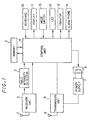
- FIG. 1 is a block diagram illustrating a portable radio terminal according to an embodiment of the invention.
- transmitted radio signals from a base station are received by a receiving antenna 1 and supplied to a receiver unit 2.
- the receiver unit 2 is a device for amplifying and demodulating the received signals, and for delivering the demodulated signals to a control unit 4.
- Received signals amplified by the receiver unit 2 are delivered to a field intensity detector 3.
- the field intensity detector 3 is a device for detecting the receiving field intensity RSSI to be supplied also to the control unit 4 referring to the received signals.
- the control programs for controlling the portable radio terminal are stored in a memory 5.
- the memory 5 is also used for storing control information generated along with various operations of the portable radio terminal, and for temporarily storing the signals to be transmitted to the base station.
- the transmission unit 6 is a device for modulating and amplifying the transmission signals to be transmitted to the base station through a transmitting antenna 9.
- the transmission unit 6 is made active with a current supplied from a power supply 7 having a switch 8 for on-off controlling the current supply to the transmission unit 6.
- a keyboard 10 is an input device provided for a user to input control information, commands, messages to be transmitted and so on.
- An LED (Light Emitting Diode) 12, a vibrator 13 and an alarm-phone 14 are provided for notifying an occurrence of events such as a new message reception.
- a mode switch 15 is used to give a command to the control unit 4 to control the portable radio terminal to operate in a power economy mode, which is a characteristic feature of the invention.
- the control unit 4 is a control center of the portable radio terminal, and electrical circuits in the control unit 4 control operations of the aforementioned parts according to programs stored in the memory 5.
- the main operations controlled by the control unit 4 are as follows;
- the above operation of controlling the operational mode includes following processes;
- the control unit 4 checks first (at step 2-1 of FIG. 2) whether the power economy mode is selected or not by the mode switch 15. When the power economy mode is selected, the control flow goes to control steps corresponding to the power economy mode shown in FIG. 3.
- the transmission signal is treated in an ordinary process (at step 2-2) and the control unit 4awaits another transmission signal returning to step 2-1.
- the ordinary process means operations in a normal mode, wherein the transmission and reception of signals are executed irrespective of the receiving field intensity RSSI and transmission signals, if there are any, are transmitted through the transmission unit 6 at once in real-time.
- the control unit 4 compares (at step 3-1) the receiving field intensity RSSI supplied from the field intensity detector 3 with the threshold value V1 registered in the memory 5. When the receiving field intensity RSSI is stronger than the threshold value V1, the control flow returns to the ordinary process (at step 2-2 of FIG. 2).
- the receiver unit 2 remains to operate normally even when the switch 8 is controlled to off-state for receiving signals transmitted from the base station.
- the control unit 4 checks whether the received signal includes a response requirement or not (at step 3-4). When the response requirement is included, the control unit 4 prepares an acknowledgment signal ACK (at step 3-5), by reading out from the memory 5 or by receiving information through the keyboard 10, which is stored in the memory 5 (at step 3-6). When there is a transmission message input through the keyboard 10, it is detected by the control unit 4 (at step 3-7) and stored in the memory 5 in the same way (at step 3-8).
- the control unit 4 checks if the power economy mode is released by the mode switch 15 (at step 3-9). When the power economy mode is released, the control flow returns to the ordinary process (at step 2-2 of FIG. 2). When the power economy mode is not released, the control unit 4 compares the receiving field intensity RSSI at that time with the threshold value V2 registered in the memory 5 (at step 3-10).
- any acknowledgment signal ACK required from the base station or transmission messages input for transmitting to the base station during the interval when the switch 8 is at off-state are safely stored in the memory 5.
- the control unit 4 controls the switch 8 to on-state for reopening current supply from the power supply 7 to the transmission unit 6 (at step 3-11), and sends a report (at step 3-12) notifying reopening of the signal transmission. Then, all the ACK signals and the transmission messages stored in the memory 5 in the steps 3-6 and 3-8 are transmitted through the transmission unit 6 (at step 3-13). After sending the stored messages, the control flow returns to step 3-1 for comparing the receiving field intensity RSSI with the threshold value V1, and the operation in the power economy mode is continued.
- the receiving field intensity is weak, and it is strong when the distance is short.
- the switch 8 is controlled to off-state for cutting the current supply from the power supply 7 to the transmission unit 6 when the receiving field intensity RSSI is weak, that is, when the distance between the portable radio terminal and the base station is long, suspending the signal transmission from the portable radio terminal, which is reopened only when the receiving field intensity RSSI becomes stronger than the threshold value V2, that is, when there is a base station nearby.
- the ordinary transmission power can be restricted in a small level sufficient for communicating with a base station at a short distance, in the embodiment, enabling efficiently saving the power consumption in the transmission unit 6.
- the portable radio terminal of the embodiment has a convenience that the user can select the power economy mode by the mode switch 15 according to his own option.
- the two threshold values V1 and V2 can be set at desired levels through the keyboard 10, allowing the user to set the power economy level according to his usage.
- the acknowledgment signal ACK and the transmission messages can be surely transmitted since they are safely stored in the memory 5 during a period when the switch 8 is controlled to off-state and the signal transmission is suspended, and they are transmitted read out from the memory 5 when the switch 8 is at on-state, that is, when the receiving field intensity is sufficiently strong.
- the transmission power can be restricted sufficiently in the embodiment without impairing the transmission quality, enabling effectively economizing the power consumption of the portable radio terminal.
Landscapes
- Engineering & Computer Science (AREA)
- Physics & Mathematics (AREA)
- Artificial Intelligence (AREA)
- Computer Vision & Pattern Recognition (AREA)
- Toxicology (AREA)
- Theoretical Computer Science (AREA)
- Health & Medical Sciences (AREA)
- General Physics & Mathematics (AREA)
- Electromagnetism (AREA)
- Computer Networks & Wireless Communication (AREA)
- General Health & Medical Sciences (AREA)
- Signal Processing (AREA)
- Mobile Radio Communication Systems (AREA)
- Transceivers (AREA)
- Transmitters (AREA)
- Telephone Function (AREA)
Abstract
Description
Claims (4)
- A portable radio terminal comprising:a field intensity detector (3) for detecting a receiving field intensity;a transmission unit (6) for transmitting radio signals to a base station;a switch (8) for supplying or cutting a power supply to said transmission unit (6);a memory (5) for storing signals to be transmitted to the base station; anda control unit (4) for controlling said switch (8) to cut said power supply to said transmission unit (6) when said receiving field intensity becomes lower than a first threshold value and to supply said power supply to said transmission unit (6) when said receiving field intensity is higher than a second threshold value, said memory (5) to store said signals to be transmitted during a time interval when said power supply is cut, and said transmission unit (6) to transmit said signals stored in said memory (5) when said power supply is supplied to said transmission unit (6).
- The portable radio terminal recited in claim 1, further comprising an input device (10) for setting levels of said first threshold value and said second threshold value from outside.
- A portable radio terminal comprising:a field intensity detector (3) for detecting a receiving field intensity;a transmission unit (6) for transmitting radio signals to a base station;a switch (8) for supplying or cutting a power supply to said transmission unit (6);a memory (5) for storing signals to be transmitted to the base station;means (15) for setting the portable radio terminal to operate in a power economy mode; anda control unit (4) for controlling, when the portable radio terminal is set to operate in said power economy mode, said switch (8) to cut said power supply to said transmission unit (6) when said receiving field intensity becomes lower than a first threshold value and to supply said power supply to said transmission unit (6) when said receiving field intensity is higher than a second threshold value, said memory (5) to store said signals to be transmitted during a time interval when said power supply is cut, and said transmission unit (6) to transmit said signals stored in said memory (5) when said power supply is supplied to said transmission unit (6).
- The portable radio terminal recited in claim 4, further comprising an input device (10) for setting levels of said first threshold value and said second threshold value from outside.
Applications Claiming Priority (3)
| Application Number | Priority Date | Filing Date | Title |
|---|---|---|---|
| JP248213/96 | 1996-09-19 | ||
| JP24821396 | 1996-09-19 | ||
| JP8248213A JP2994274B2 (en) | 1996-09-19 | 1996-09-19 | Portable mobile radio terminal |
Publications (3)
| Publication Number | Publication Date |
|---|---|
| EP0831414A2 true EP0831414A2 (en) | 1998-03-25 |
| EP0831414A3 EP0831414A3 (en) | 1998-12-09 |
| EP0831414B1 EP0831414B1 (en) | 2003-04-23 |
Family
ID=17174872
Family Applications (1)
| Application Number | Title | Priority Date | Filing Date |
|---|---|---|---|
| EP97250281A Expired - Lifetime EP0831414B1 (en) | 1996-09-19 | 1997-09-18 | A portable radio terminal |
Country Status (6)
| Country | Link |
|---|---|
| EP (1) | EP0831414B1 (en) |
| JP (1) | JP2994274B2 (en) |
| CN (1) | CN1086540C (en) |
| AU (1) | AU715792B2 (en) |
| CA (1) | CA2215768A1 (en) |
| DE (1) | DE69721166T2 (en) |
Cited By (12)
| Publication number | Priority date | Publication date | Assignee | Title |
|---|---|---|---|---|
| US6037879A (en) * | 1997-10-02 | 2000-03-14 | Micron Technology, Inc. | Wireless identification device, RFID device, and method of manufacturing wireless identification device |
| WO2000023941A1 (en) * | 1998-10-21 | 2000-04-27 | Micron Communications, Inc. | Wireless identification device, rfid device, and method of manufacturing a wireless identification device |
| US6243568B1 (en) * | 1997-03-22 | 2001-06-05 | Sharp Laboratories Of America, Inc. | System and method for intuitively indicating signal quality in a wireless digital communications network |
| EP1168645A2 (en) * | 2000-06-06 | 2002-01-02 | Fraunhofer-Gesellschaft Zur Förderung Der Angewandten Forschung E.V. | Transmitter-receiver circuit |
| EP1204261A2 (en) * | 2000-10-11 | 2002-05-08 | Nec Corporation | Wireless communication device with selective power supply function |
| WO2002071328A1 (en) * | 2001-03-02 | 2002-09-12 | Schlumberger Systemes | Integrated circuit card with built-in power supply |
| US6487419B1 (en) * | 1998-08-06 | 2002-11-26 | Ericsson Inc. | Systems and methods for management of current consumption and performance in a receiver down converter of a wireless device |
| WO2004013806A1 (en) * | 2002-07-30 | 2004-02-12 | Koninklijke Philips Electronics N.V. | Transponder with a controllable power-on-reset circuit |
| EP2194695A1 (en) * | 2000-08-11 | 2010-06-09 | Sony Corporation | Mobile phone |
| US7811163B2 (en) | 2005-07-27 | 2010-10-12 | Ashley Ratcliffe | Transmitter tag |
| EP2615867A1 (en) * | 2012-01-12 | 2013-07-17 | Alcatel Lucent | Method for selecting a transmission mode, mobile station, network node, and communication network thereof |
| US9942377B2 (en) | 2000-08-11 | 2018-04-10 | Drnc Holdings, Inc. | Portable telephone |
Families Citing this family (13)
| Publication number | Priority date | Publication date | Assignee | Title |
|---|---|---|---|---|
| KR100652142B1 (en) * | 1998-06-23 | 2007-03-02 | 주식회사 팬택앤큐리텔 | How to save battery of mobile terminal |
| KR100353460B1 (en) * | 1999-12-29 | 2002-09-19 | 삼성전자 주식회사 | Method for controlling power in wireless telephone set |
| JP2003037545A (en) | 2001-07-23 | 2003-02-07 | Nec Corp | Mobile station with short range radio unction and reduction method for its power consumption |
| KR100630174B1 (en) * | 2001-11-15 | 2006-09-29 | 삼성전자주식회사 | Method for processing radio wave information received from a phone jammer |
| JP4186619B2 (en) * | 2002-12-25 | 2008-11-26 | 日本電気株式会社 | Communication device, transmission control method, threshold control method and wireless network system in wireless network |
| CN1306842C (en) * | 2004-12-21 | 2007-03-21 | 北京中星微电子有限公司 | A power supply management method and apparatus for mobile communication terminal |
| JP2006238270A (en) * | 2005-02-28 | 2006-09-07 | Toshiba Corp | Information processor |
| US8060041B2 (en) * | 2006-02-09 | 2011-11-15 | Qualcomm, Incorporated | Adaptive receiver for wireless communication device |
| CN101977067A (en) * | 2010-11-04 | 2011-02-16 | 钜泉光电科技(上海)股份有限公司 | Low-power consumption power carrier communication circuit and method |
| JP5923937B2 (en) * | 2011-11-10 | 2016-05-25 | 富士通株式会社 | Transmission control method and communication apparatus |
| JP2012231534A (en) * | 2012-07-25 | 2012-11-22 | Toshiba Corp | Wireless device and control method |
| CN106788684A (en) * | 2017-01-18 | 2017-05-31 | 成都科脉通信技术有限公司 | Removable satellite communication base station and its anti-interference method |
| CN112769453B (en) * | 2020-11-09 | 2023-10-27 | 泰斗微电子科技有限公司 | Signal receiving and transmitting control method of Beidou active antenna |
Citations (2)
| Publication number | Priority date | Publication date | Assignee | Title |
|---|---|---|---|---|
| EP0586170A1 (en) * | 1992-09-04 | 1994-03-09 | Nokia Mobile Phones Ltd. | A mobile radio communications unit |
| US5479172A (en) * | 1994-02-10 | 1995-12-26 | Racom Systems, Inc. | Power supply and power enable circuit for an RF/ID transponder |
Family Cites Families (1)
| Publication number | Priority date | Publication date | Assignee | Title |
|---|---|---|---|---|
| FI96656C (en) * | 1992-11-27 | 1996-07-25 | Nokia Telecommunications Oy | radio system |
-
1996
- 1996-09-19 JP JP8248213A patent/JP2994274B2/en not_active Expired - Fee Related
-
1997
- 1997-09-18 CA CA002215768A patent/CA2215768A1/en not_active Abandoned
- 1997-09-18 AU AU38333/97A patent/AU715792B2/en not_active Ceased
- 1997-09-18 EP EP97250281A patent/EP0831414B1/en not_active Expired - Lifetime
- 1997-09-18 DE DE69721166T patent/DE69721166T2/en not_active Expired - Fee Related
- 1997-09-18 CN CN97116911A patent/CN1086540C/en not_active Expired - Fee Related
Patent Citations (2)
| Publication number | Priority date | Publication date | Assignee | Title |
|---|---|---|---|---|
| EP0586170A1 (en) * | 1992-09-04 | 1994-03-09 | Nokia Mobile Phones Ltd. | A mobile radio communications unit |
| US5479172A (en) * | 1994-02-10 | 1995-12-26 | Racom Systems, Inc. | Power supply and power enable circuit for an RF/ID transponder |
Cited By (22)
| Publication number | Priority date | Publication date | Assignee | Title |
|---|---|---|---|---|
| US6243568B1 (en) * | 1997-03-22 | 2001-06-05 | Sharp Laboratories Of America, Inc. | System and method for intuitively indicating signal quality in a wireless digital communications network |
| US6380845B2 (en) | 1997-10-02 | 2002-04-30 | Micron Technology, Inc. | Wireless identification device, RFID device, and method of manufacturing wireless identification device |
| US6037879A (en) * | 1997-10-02 | 2000-03-14 | Micron Technology, Inc. | Wireless identification device, RFID device, and method of manufacturing wireless identification device |
| US6487419B1 (en) * | 1998-08-06 | 2002-11-26 | Ericsson Inc. | Systems and methods for management of current consumption and performance in a receiver down converter of a wireless device |
| WO2000023941A1 (en) * | 1998-10-21 | 2000-04-27 | Micron Communications, Inc. | Wireless identification device, rfid device, and method of manufacturing a wireless identification device |
| EP1168645A2 (en) * | 2000-06-06 | 2002-01-02 | Fraunhofer-Gesellschaft Zur Förderung Der Angewandten Forschung E.V. | Transmitter-receiver circuit |
| EP1168645A3 (en) * | 2000-06-06 | 2004-12-29 | Fraunhofer-Gesellschaft zur Förderung der angewandten Forschung e.V. | Transmitter-receiver circuit |
| US7978150B2 (en) | 2000-08-11 | 2011-07-12 | Sony Corporation | Portable telephone |
| US9075504B2 (en) | 2000-08-11 | 2015-07-07 | Drnc Holdings, Inc. | Portable telephone |
| EP2194695A1 (en) * | 2000-08-11 | 2010-06-09 | Sony Corporation | Mobile phone |
| US9942377B2 (en) | 2000-08-11 | 2018-04-10 | Drnc Holdings, Inc. | Portable telephone |
| US9459763B2 (en) | 2000-08-11 | 2016-10-04 | Drnc Holdings, Inc. | Portable telephone |
| US8842106B2 (en) | 2000-08-11 | 2014-09-23 | Drnc Holdings, Inc. | Portable telephone |
| EP1204261A3 (en) * | 2000-10-11 | 2003-10-01 | Nec Corporation | Wireless communication device with selective power supply function |
| EP1204261A2 (en) * | 2000-10-11 | 2002-05-08 | Nec Corporation | Wireless communication device with selective power supply function |
| WO2002071328A1 (en) * | 2001-03-02 | 2002-09-12 | Schlumberger Systemes | Integrated circuit card with built-in power supply |
| WO2004013806A1 (en) * | 2002-07-30 | 2004-02-12 | Koninklijke Philips Electronics N.V. | Transponder with a controllable power-on-reset circuit |
| CN100378755C (en) * | 2002-07-30 | 2008-04-02 | Nxp股份有限公司 | Transponder with a controllable power-on-reset circuit |
| US7423517B2 (en) | 2002-07-30 | 2008-09-09 | Nxp B.V. | Transponder with a controllable power-on-reset circuit |
| US7811163B2 (en) | 2005-07-27 | 2010-10-12 | Ashley Ratcliffe | Transmitter tag |
| WO2013104445A1 (en) * | 2012-01-12 | 2013-07-18 | Alcatel Lucent | Method for selecting a transmission mode, mobile station, network node, and communication network thereof |
| EP2615867A1 (en) * | 2012-01-12 | 2013-07-17 | Alcatel Lucent | Method for selecting a transmission mode, mobile station, network node, and communication network thereof |
Also Published As
| Publication number | Publication date |
|---|---|
| CA2215768A1 (en) | 1998-03-19 |
| CN1086540C (en) | 2002-06-19 |
| DE69721166T2 (en) | 2004-03-11 |
| AU3833397A (en) | 1998-03-26 |
| EP0831414A3 (en) | 1998-12-09 |
| AU715792B2 (en) | 2000-02-10 |
| JP2994274B2 (en) | 1999-12-27 |
| JPH1098427A (en) | 1998-04-14 |
| EP0831414B1 (en) | 2003-04-23 |
| DE69721166D1 (en) | 2003-05-28 |
| CN1180286A (en) | 1998-04-29 |
Similar Documents
| Publication | Publication Date | Title |
|---|---|---|
| EP0831414A2 (en) | A portable radio terminal | |
| US5825761A (en) | Radio communication equipment with transmission rate regulating function | |
| US5220678A (en) | Method and apparatus for adjusting the power of a transmitter | |
| US5627882A (en) | Enhanced power saving method for hand-held communications system and a hand-held communications system therefor | |
| EP0282087B1 (en) | Radio channel search system | |
| US5031231A (en) | Mobile telephone station with power saving circuit | |
| EP2134130A3 (en) | Transmission power control device and method, mobile station, and communication device in mobile communication system | |
| CA2328307A1 (en) | Device and method for controlling transmission on reverse link in mobile communication system | |
| RU2001101432A (en) | METHOD OF SUPPORT OF INTERMEDIATE TRANSMISSION MODE ON THE BASIC STATION OF THE MOBILE COMMUNICATION SYSTEM | |
| JPH02256331A (en) | Radio communication system | |
| JP2689932B2 (en) | Radio selective call receiver | |
| US5960327A (en) | Method for a transceiver to select a channel | |
| US9119161B2 (en) | Method for controlling power in wireless telephone set | |
| KR20010018527A (en) | Equipment and mthod for power saving of mobile wireless communication terminal | |
| GB2348339A (en) | A mobile station comprising a control section for switching to a calling mode when reception from a satellite is below a threshold. | |
| KR100238729B1 (en) | Method and apparatus for extending battery life of two-way radio communication terminal | |
| JPH0695651B2 (en) | Wireless communication device | |
| JP2000269884A (en) | Radio communication system | |
| JP3101834B2 (en) | Wireless transmission power control method | |
| JPH10145865A (en) | Communication portable terminal | |
| US5550832A (en) | Time division multiple access radio transmission activated receiver switch | |
| JP3379366B2 (en) | Relay broadcast device and broadcast receiving device | |
| JPH1099285A (en) | Patient monitor device | |
| KR910002153A (en) | Power Saving Method and Device of Wireless Communication Device | |
| JP3232894B2 (en) | Wireless device |
Legal Events
| Date | Code | Title | Description |
|---|---|---|---|
| PUAI | Public reference made under article 153(3) epc to a published international application that has entered the european phase |
Free format text: ORIGINAL CODE: 0009012 |
|
| AK | Designated contracting states |
Kind code of ref document: A2 Designated state(s): DE GB |
|
| AX | Request for extension of the european patent |
Free format text: AL;LT;LV;RO;SI |
|
| PUAL | Search report despatched |
Free format text: ORIGINAL CODE: 0009013 |
|
| AK | Designated contracting states |
Kind code of ref document: A3 Designated state(s): AT BE CH DE DK ES FI FR GB GR IE IT LI LU MC NL PT SE |
|
| AX | Request for extension of the european patent |
Free format text: AL;LT;LV;RO;SI |
|
| 17P | Request for examination filed |
Effective date: 19990315 |
|
| AKX | Designation fees paid |
Free format text: DE GB |
|
| GRAH | Despatch of communication of intention to grant a patent |
Free format text: ORIGINAL CODE: EPIDOS IGRA |
|
| GRAH | Despatch of communication of intention to grant a patent |
Free format text: ORIGINAL CODE: EPIDOS IGRA |
|
| GRAA | (expected) grant |
Free format text: ORIGINAL CODE: 0009210 |
|
| AK | Designated contracting states |
Designated state(s): DE GB |
|
| REG | Reference to a national code |
Ref country code: GB Ref legal event code: FG4D |
|
| REF | Corresponds to: |
Ref document number: 69721166 Country of ref document: DE Date of ref document: 20030528 Kind code of ref document: P |
|
| PLBE | No opposition filed within time limit |
Free format text: ORIGINAL CODE: 0009261 |
|
| STAA | Information on the status of an ep patent application or granted ep patent |
Free format text: STATUS: NO OPPOSITION FILED WITHIN TIME LIMIT |
|
| 26N | No opposition filed |
Effective date: 20040126 |
|
| PGFP | Annual fee paid to national office [announced via postgrant information from national office to epo] |
Ref country code: GB Payment date: 20050914 Year of fee payment: 9 |
|
| PGFP | Annual fee paid to national office [announced via postgrant information from national office to epo] |
Ref country code: DE Payment date: 20050915 Year of fee payment: 9 |
|
| PG25 | Lapsed in a contracting state [announced via postgrant information from national office to epo] |
Ref country code: DE Free format text: LAPSE BECAUSE OF NON-PAYMENT OF DUE FEES Effective date: 20070403 |
|
| GBPC | Gb: european patent ceased through non-payment of renewal fee |
Effective date: 20060918 |
|
| PG25 | Lapsed in a contracting state [announced via postgrant information from national office to epo] |
Ref country code: GB Free format text: LAPSE BECAUSE OF NON-PAYMENT OF DUE FEES Effective date: 20060918 |