EP0843468A2 - EPG apparatus and its control method - Google Patents
EPG apparatus and its control method Download PDFInfo
- Publication number
- EP0843468A2 EP0843468A2 EP97309149A EP97309149A EP0843468A2 EP 0843468 A2 EP0843468 A2 EP 0843468A2 EP 97309149 A EP97309149 A EP 97309149A EP 97309149 A EP97309149 A EP 97309149A EP 0843468 A2 EP0843468 A2 EP 0843468A2
- Authority
- EP
- European Patent Office
- Prior art keywords
- epg
- external apparatus
- program
- video
- communication means
- Prior art date
- Legal status (The legal status is an assumption and is not a legal conclusion. Google has not performed a legal analysis and makes no representation as to the accuracy of the status listed.)
- Ceased
Links
Images


Classifications
-
- H—ELECTRICITY
- H04—ELECTRIC COMMUNICATION TECHNIQUE
- H04N—PICTORIAL COMMUNICATION, e.g. TELEVISION
- H04N21/00—Selective content distribution, e.g. interactive television or video on demand [VOD]
- H04N21/40—Client devices specifically adapted for the reception of or interaction with content, e.g. set-top-box [STB]; Operations thereof
- H04N21/47—End-user applications
- H04N21/472—End-user interface for requesting content, additional data or services; End-user interface for interacting with content, e.g. for content reservation or setting reminders, for requesting event notification, for manipulating displayed content
- H04N21/47214—End-user interface for requesting content, additional data or services; End-user interface for interacting with content, e.g. for content reservation or setting reminders, for requesting event notification, for manipulating displayed content for content reservation or setting reminders; for requesting event notification, e.g. of sport results or stock market
-
- H—ELECTRICITY
- H04—ELECTRIC COMMUNICATION TECHNIQUE
- H04N—PICTORIAL COMMUNICATION, e.g. TELEVISION
- H04N21/00—Selective content distribution, e.g. interactive television or video on demand [VOD]
- H04N21/40—Client devices specifically adapted for the reception of or interaction with content, e.g. set-top-box [STB]; Operations thereof
- H04N21/47—End-user applications
- H04N21/482—End-user interface for program selection
-
- H—ELECTRICITY
- H04—ELECTRIC COMMUNICATION TECHNIQUE
- H04N—PICTORIAL COMMUNICATION, e.g. TELEVISION
- H04N5/00—Details of television systems
- H04N5/76—Television signal recording
- H04N5/765—Interface circuits between an apparatus for recording and another apparatus
- H04N5/775—Interface circuits between an apparatus for recording and another apparatus between a recording apparatus and a television receiver
Definitions
- the present invention relates to an EPG (Electric Programming Guide) apparatus, that is, an apparatus having an EPG decoder.
- EPG Electronic Programming Guide
- the present invention relates to a technology of displaying data concerning other external equipment on an EPG screen.
- an EPG is introduced in order to improve the convenience of program selection.
- EPG data such as the number of a transmitted channel, the name of a transmitted program and a schedule is decoded by an EPG decoder employed in the receiver where an EPG screen is displayed on a television monitor.
- an apparatus employing an EPG decoder displays information on received programs on an EPG screen, the apparatus does not display data concerning connection with other external equipment.
- the present invention provides a system comprising an EPG apparatus and an external apparatus connected to the EPG apparatus by using a communication means wherein, when the EPG apparatus detects the connection thereof to the external apparatus by means of the communication means, the EPG apparatus displays data concerning the external apparatus on an EPG screen of a display means employed in the EPG apparatus or an EPG screen of an external display means along with EPG data resulting from decoding carried out by an EPG decoder embedded in the EPG apparatus.
- an EPG apparatus is capable of detecting the fact that the EPG apparatus is connected to an external apparatus by using a communication means.
- the EPG apparatus displays data concerning the external equipment on an EPG screen of a display means employed in the EPG apparatus or an EPG screen of an external display means along with EPG data resulting from decoding carried out by an EPG decoder embedded in the EPG apparatus.
- Fig. 1 is a block diagram showing the configuration of a system using AV links.
- the system comprises first to third AV apparatuses connected by AV links.
- the AV apparatuses include a video tape recorder referred to hereafter simply as a VTR, a television receiver referred to hereafter simply as a TV and a tuner.
- the AV link conforms to a system EN-50157 standardized in Europe.
- the AV link is 21-pin SCART connection which includes bi-directional analog connection for transmitting both audio and video signals and bi-directional digital connection for transmitting other kinds of signal such as a control command.
- the first and third AV apparatuses are provided with SCART connectors 1 and 4 respectively.
- the second AV apparatus has SCART connectors 2 and 3.
- a SCART cable 5 is provided between the first and second SCART connectors whereas a SCART cable 6 is provide between the third and fourth SCART connectors.
- the SCART cable 5 includes a digital control signal line 7 connecting the tenth pins (pins-10) of the SCART connectors 1 and 2 to each other and analog information signal lines 8 for separately transmitting audio and video signals.
- the SCART cable 6 includes a digital control signal line 9 connecting the tenth pins of the SCART connectors 3 and 4 to each other and analog information signal lines 10 for separately transmitting audio and video signals.
- the analog and video signals are abbreviated hereafter to an AV signal.
- the first AV apparatus employs a microcontroller 11 for inputting and outputting digital control signals described earlier.
- An input terminal of the microcontroller 11 is connected to the tenth pin of the SCART connector 1.
- a bidirectional arrow passing through the tenth pin indicates that the digital control signal line 7 is a bi-directional bus line.
- a voltage +Vcc of a power supply is supplied to the input terminal of the microcontroller 11 through a resistor 13.
- an output terminal of the microcontroller 11 is connected to the base of an output transistor 12.
- the collector of the output transistor 12 is connected to the junction between the input terminal of the microcontroller 11 and the resistor 13, that is, the end of the resistor 13 on the opposite side to the power-supply voltage +Vcc.
- the second and third AV apparatuses also employ microcontrollers 14 and 17, resistors 16 and 19 and output transistors 15 and 18 respectively.
- the input terminal of the microcontroller 14 is connected to the tenth pins of the SCART connectors 2 and 3 whereas the input terminal of the microcontroller 17 is connected to the tenth pin of the SCART connector 4.
- the input terminals of the microcontrollers 14 and 17 are connected to the power-supply voltage +Vcc through their respective resistors 16 and 19 and output terminals thereof are connected to their respective output transistors 15 and 18 in the same way as the first AV apparatus.
- the first to third AV apparatuses are each provided with a block, which is not shown in the figure, for processing an AV signal.
- bi-directional arrows on the connections of the analog information signal line 8 to the SCART connectors 1 and 2 indicate that an analog information signal can be transmitted in both directions through the analog information signal line 8.
- bi-directional arrows on the connections of the analog information signal line 10 to the SCART connectors 3 and 4 indicate that an analog information signal can be transmitted in both directions through the analog information signal line 10.
- the AV signal and the digital control signals can be transmitted among the AV apparatuses in both directions.
- Fig. 2 is a block diagram showing the configuration of a first embodiment implementing a system to which the present invention is applied.
- the system comprises a TV 21 and a VTR 22.
- an EPG decoder is embedded in both the TV 21 and the VTR 22.
- a SCART cable 28 is used for connecting a SCART connector 24 provided on the TV 21 to a SCART connector 25 of the VTR 22.
- the SCART cable 28 includes a digital control signal line 29 connecting the tenth pins of the SCART connectors 24 and 25 to each other and an analog information signal line 30 for transmitting an AV signal.
- the digital control signal line 29 and the analog information signal line 30 are capable of transmitting a digital control signal and an AV signal respectively in both directions.
- the TV 21 comprises a controller 35 for implementing functions such as management and control of the TV 21 as a whole, a display unit 36 for outputting pictures and sound, a tuner 37, an on-screen-display (OSD) unit 38, an EPG decoder 39 and a switch 40 for selecting a signal output by the tuner 37, the OSD unit 38 or the analog information signal line 30 as an input to the display unit 36.
- a controller 35 for implementing functions such as management and control of the TV 21 as a whole, a display unit 36 for outputting pictures and sound, a tuner 37, an on-screen-display (OSD) unit 38, an EPG decoder 39 and a switch 40 for selecting a signal output by the tuner 37, the OSD unit 38 or the analog information signal line 30 as an input to the display unit 36.
- OSD on-screen-display
- the VTR 22 comprises a controller 41 for implementing functions such as management and control of the VTR 22 as a whole, an AV (audio/video) source 42, an OSD unit 43 and a switch 44 for selecting a signal output by the AV source 42 or the OSD unit 43 as an input to the analog information signal line 30.
- the AV source 42 has functions of a tuner and an AV-signal video-recording/playback system.
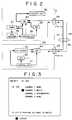
- an EPG screen displayed initially on the display unit 36 of the TV 21 is like one shown in Fig. 3.
- the display screen merely shows channels 1 to 4, which shows broadcasted programs received by the tuner 37, and does not make the TV watcher aware of the fact that the VTR 22 is connected to the TV 21.
- the TV 21 and the VTR 22 are capable of exchanging data with each other through the digital control signal line 29.
- the TV 21 carries out an operation such as polling to detect the connection with the VTR 22.
- a typical way to detect the connection with other pieces of equipment including the VTR 22 is assignment of a fixed address to each of the pieces of equipment. For example, an address of 0001 is assigned to the VTR 22.
- the controller 35 employed in the TV 21 outputs a packet including the address assigned to the VTR 22 to the digital control signal line 29.
- the controller 41 employed in the VTR 22 returns an ACK (acknowledge) signal to the TV 21 in response to the packet.
- the ACK signal received by the controller 35 employed in the TV 21 is a detected evidence of the existence of equipment to which the packet has been transmitted.
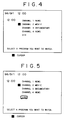
- the controller 35 employed in the TV 21 controls the OSD unit 38 so as to display a string of characters "VTR" on the EPG screen of the display unit 36 to indicate the existence of the VTR 22 along with the broadcasted channels received by the internal tuner 37 in the TV 21 as shown in Fig. 4.
- an icon to represent the VTR 22 can also be displayed as shown in Fig. 5.
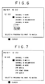
- such an icon and the string of characters "VTR” can both be displayed as shown in Fig. 6.
- the remote controller While watching the screen shown in Fig. 4, the user selects a broadcasted program or the VTR by operating a remote controller which is not shown in the figure.
- the remote controller is provided with up and down move keys and a confirm key.
- the up or down move key is operated to move a cursor on the display screen up or down to a position beside a desired broadcasted program or beside the string of characters "VTR".
- the cursor is moved to a position beside a movie of channel 2.
- the confirm key is pressed to indicate the selection of a broadcasted program or a program to be played back from the VTR 22.
- the controller 35 transmits a station-selection control signal to the tuner 37 and an AV signal of the program selected by the tuner 37 in accordance with the station-selection control signal is output to the display unit 36 by way of the switch 40. If a program to be played back from the VTR 22 is selected, on the other hand, the controller 35 sends the VTR 22 a playback command addressed to the VTR 22 through the digital control signal line 29 connected to the tenth pin of the SCART connector 24. The playback command is supplied to the controller 41 employed in the VTR 22 through the tenth pin of the SCART connector 25 provided on the VTR 22.
- the controller 41 receives the playback command, the controller 41 outputs a control signal to the AV source 42, requesting the AV source to output a played-back AV signal from a video tape to the analog information signal line 30 by way of the switch 44 and the SCART connector 25.
- the AV signal output to the analog information signal line 30 is supplied to the display unit 36 employed in the TV 21 by way of the SCART connector 24 and the switch 40.
- either a broadcasted program or a program recorded in advance can be selected in such a uniform manner that there is no need to distinguish one from another, raising the degree of usage convenience of the system.
- the VTR 22 may employ external memory units as video-recording media or as video-recording sub-channels. In this case, it is necessary to read out the contents of what are recorded in the media.
- the controller 35 employed in the TV 21 utilizes a control signal transmitted through the digital control signal line 29 to read out the video-recording contents and then display the contents resulting from the read operation along with the string of characters "VTR" as shown in Fig. 7.
- the TV 21 transmits an instruction to select the program and a playback command to play back the selected program to the VTR 22.
- the VTR 22 starts the operation to play back the desired program and transmits the played-back program to the display unit 36 employed in the TV 21.
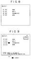
- an initial EPG screen is displayed on the display unit 36 as shown in Fig. 8.
- the display screen does not make the TV watcher aware of the fact that a VTR is connected to the TV 21.
- the TV 21 carries out an operation such as polling to detect the connection with the VTR 22. Detecting the connection of the VTR 22 to the TV 21, a screen A indicating the connection with the VTR 22 and the character B indicating the availability of a function for making video-recording reservations are displayed on the EPG screen of the display unit 36 along with the broadcasted channels received by the internal tuner 37 employed in the TV 21 typically like ones shown in Fig. 9.
- the remote controller is provided with up, down, right, and left move keys and a confirm key.
- the up or down move key is operated to move a cursor on the display screen up or down to select a desired program.
- the right or left move key is operated to select the screen A.
- the confirm key is pressed to confirm the video-recording reservation.
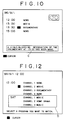
- the TV 21 transmits data representing the reserved channel and the reservation time to the VTR 22 through the digital control signal line 29 and displays a message C like one shown in Fig. 10 to indicate that the video-recording reservation has been made.
- Fig. 11 is a block diagram showing a second configuration of a system to which the present invention is applied.
- the system comprises a TV 21 and a satellite broadcasting receiver 23 which is referred to hereafter simply as a SAT.
- a SAT satellite broadcasting receiver 23
- an EPG decoder is embedded in both the TV 21 and the SAT 23.
- a SCART cable 31 is used for connecting a SCART connector 24 provided on the TV 21 to a SCART connector 26 of the SAT 23.
- the SCART cable 31 includes a digital control signal line 32 connecting the tenth pins of the SCART connectors 24 and 26 to each other and an analog information signal line 33.
- the SAT 23 comprises a controller 51 for implementing functions such as management and control of the SAT 23 as a whole, a tuner 52, an OSD unit 53, an EPG decoder 54 and a switch 55 for selecting a signal output by the tuner 52 or the OSD unit 53 as an input to the analog information signal line 33.
- an initial EPG screen is displayed on the display unit 36 as shown in Fig. 3.
- the display screen does not make the TV watcher aware of the fact that the SAT 23 is connected to the TV 21.
- the TV 21 carries out an operation such as polling to detect the connection with the SAT 23.
- EPG data from the SAT 23 is received through the digital control signal line 32 and displayed to show broad-casted programs received by the SAT 23 on the EPG screen along with broadcasted programs received by the tuner 37 employed in the TV 21 itself as shown in Fig. 12.
- the SAT programs are displayed in a screen area enclosed in a frame D.
- the user While watching the screen shown in Fig. 12, the user selects a broadcasted program received by the TV 21 or a broadcasted program received by the SAT 23.
- the operation to select a program in this case is not the same as the system shown in Fig. 2. That is to say, when a broad-casted program received by the SAT 23 is selected, the TV 21 transmits a command to select the desired program to the SAT 23 through the digital control signal line 32. Receiving the command, the SAT 23 carries out required operations such as tuning and, at the same time, the TV 21 displays an AV signal on the display unit 36 employed therein.
- either a broadcasted program received by the TV 21 or a broadcasted program received by the SAT 23 can be selected in such a uniform manner that there is no need to distinguish one from another, raising the degree of usage convenience of the system.
- a TV is connected to a VTR and a SAT by an AV link as shown in Figs. 2 and llrespectively.
- the AV link can be implemented by a digital bus like the IEEE1394 bus or another connection system.
- one unit of TV is connected to one unit of VTR.
- the first AV apparatus is a TV including no embedded EPG decoder therein whereas the second and third AV apparatuses are a SAT and a VTR respectively which each include an embedded EPG decoder.
- the first AV apparatus detects connection with the second AV apparatus (the SAT) and the third AV apparatus (the VTR).
- the EPG screen on the first AV apparatus can be changed.
- one unit of TV is connected to one unit of SAT.
- three or more AV apparatuses can be connected to each other in a configuration like the one shown in Fig. 1.
- the first AV apparatus is a TV including no embedded EPG decoder therein whereas the second and third AV apparatuses are a SAT and a cable TV receiver respectively which each include an embedded EPG decoder.
- the first AV apparatus detects connection with the second AV apparatus (the SAT) and the third AV apparatus (the cable TV receiver).
- the EPG screen on the first AV apparatus (TV) can be changed.
- a video tape is used as a medium for video-recording and playing back an AV signal.
- a video-recording medium other than a magnetic tape can also be used as well.
- Examples of a video-recording medium other than a magnetic tape are a video disk for playback purposes only or for both playback and video-recording purposes.
- the present invention can be applied not only to a ground-wave TV, a SAT and a cable TV receiver, but also to all kinds of ordinary EPG equipment, apparatuses each including an embedded EPG decoder.
Abstract
Description
Claims (26)
- A system comprising an EPG apparatus and an external apparatus connected to said EPG apparatus by a communication means wherein, when said EPG apparatus detects connection of said external apparatus to said EPG apparatus by using said communication means, said EPG apparatus displays data regarding said external apparatus on an EPG screen thereof along with EPG data resulting from decoding carried out by an EPG decoder embedded in said EPG apparatus.
- A system according to claim 1 wherein said data regarding said external apparatus is a character or an image indicating said external apparatus.
- A system according to claim 1 or 2 wherein said data regarding said external apparatus includes information on programs that can be generated by said external apparatus.
- A system according to claim 1, 2 or 3 wherein said EPG apparatus has a display means and said EPG screen is displayed on said display means.
- A system according to claim 1, 2, 3 or 4 further including a second external apparatus other than said external apparatus connected to said EPG apparatus by said communication means, said second external apparatus has a display means and said EPG screen is displayed on said display means.
- A system according to any one of the preceding claims wherein, when said data reaardina said external apparatus displayed on said EPG screen is selected, said EPG apparatus issues an instruction to said external apparatus through said communication means to request said external apparatus to start outputting a program indicated by said selected data.
- A system according to claim 3 wherein a program that said external apparatus is capable of outputting is a program recorded in said external apparatus in advance.
- A system according to any one of the preceding claims wherein said external apparatus includes an EPG decoder.
- A system according to any one of the preceding claims wherein said external apparatus has a function to make video-recording reservation of a program to be received by said EPG apparatus and, when an operation to make a video-recording reservation of a program is carried out via said EPG screen, said EPG apparatus issues a video-recording-reserva tion instruction to said external apparatus through said communication means.
- A system according to claim 9 wherein, after an operation to make a video-recording reservation of a program has been carried out, said EPG apparatus displays a message on said EPG screen to indicate that said operation to make a video-recording reservation of a program has been carried out.
- A system according to claim 1 wherein said external apparatus is a VTR.
- A system according to claim 1 wherein said external apparatus is a satellite broadcasting receiver.
- A system according to any one of the preceding claims wherein an AV link is used as said communication means.
- A system according to any one of claims 1 to 12 wherein the IEEE1394 bus is used as said communication means.
- A control method for controlling a system including an EPG apparatus and an external apparatus connected to said EPG apparatus by a communication means, said control method comprising the step of;
displaying by said EPG apparatus, when said EPG apparatus detects connection of said external apparatus to said EPG apparatus by using said communication means, data regarding said external apparatus on an EPG screen thereof along with EPG data resulting from decoding carried out by an EPG decoder embedded in said EPG apparatus. - A control method according to claim 15 wherein said data regarding said external apparatus is a character or an image representing said external apparatus.
- A control method according to claim 15 or 16 wherein said data regarding said external apparatus includes information on programs that can be generated by said external apparatus.
- A control method according to claim 15, 16 or 17 wherein said EPG apparatus has a display means and said EPG screen is displayed on said display means.
- A control method according to claim 15, 16, 17 or 18 wherein said system further includes a second external apparatus other than said external apparatus connected to said EPG apparatus by said communication means, said second external apparatus has a display means and said EPG screen is displayed on said display means.
- A control method according to any one of claims 15 to 19 whereby, when said data regarding said external apparatus displayed on said EPG screen is selected, said EPG apparatus issues an instruction to said external apparatus through said communication means to request said external apparatus to start outputting a program indicated by said selected data.
- A control method according to claim 17 wherein a program that said external apparatus is capable of outputting is a program recorded in said external apparatus in advance.
- A control method according to any one of claims 15 to 21 wherein said external apparatus includes an EPG decoder.
- A control method according to any one of claims 15 to 22 wherein said
external apparatus has a function to make video-recording reservation of a program to be received by said EPG apparatus and whereby, when an operation to make a video-recording reservation of a program is carried out via said EPG screen, said EPG apparatus issues a video-recording-reservation instruction to said external apparatus through said communication means. - A control method according to claim 23 whereby, after an operation to make a video-recording reservation of a program has been carried out, said EPG apparatus displays a message on said EPG screen to indicate that said operation to make a video-recording reservation of a program has been carried out.
- An EPG apparatus comprising:an EPG decoder;a communication means for communicating with an external apparatus; anda control means,wherein, when said EPG apparatus detects connection of said external apparatus to said EPG apparatus by using said communication means, said control means displays data regarding said external apparatus along with EPG data resulting from decoding carried out by an EPG decoder embedded in said EPG apparatus.
- An EPG apparatus according to claim 25 further including a display means.
Applications Claiming Priority (2)
| Application Number | Priority Date | Filing Date | Title |
|---|---|---|---|
| JP32344196A JP3528480B2 (en) | 1996-11-19 | 1996-11-19 | EPG device and control method thereof |
| JP323441/96 | 1996-11-19 |
Publications (2)
| Publication Number | Publication Date |
|---|---|
| EP0843468A2 true EP0843468A2 (en) | 1998-05-20 |
| EP0843468A3 EP0843468A3 (en) | 1998-12-23 |
Family
ID=18154710
Family Applications (1)
| Application Number | Title | Priority Date | Filing Date |
|---|---|---|---|
| EP97309149A Ceased EP0843468A3 (en) | 1996-11-19 | 1997-11-13 | EPG apparatus and its control method |
Country Status (3)
| Country | Link |
|---|---|
| US (1) | US5991832A (en) |
| EP (1) | EP0843468A3 (en) |
| JP (1) | JP3528480B2 (en) |
Cited By (38)
| Publication number | Priority date | Publication date | Assignee | Title |
|---|---|---|---|---|
| EP0889649A2 (en) * | 1997-07-04 | 1999-01-07 | Sony Corporation | Control system and method, reproducing apparatus, output apparatus, and transmission medium |
| EP0920200A1 (en) * | 1997-11-26 | 1999-06-02 | SANYO ELECTRIC Co., Ltd. | Digital broadcast receiver |
| WO2000005881A1 (en) * | 1998-07-22 | 2000-02-03 | Thomson Licensing S.A. | Use of on-screen display (osd) for supplying control and auxiliary information to external devices |
| WO2000013408A1 (en) * | 1998-08-26 | 2000-03-09 | Thomson Licensing S.A. | A method for automatically determining the configuration of a multi-input video processing apparatus |
| EP0991272A1 (en) * | 1998-10-02 | 2000-04-05 | Hitachi, Ltd. | EPG screen generating method and apparatus and EPG information transmission apparatus |
| EP1014715A2 (en) * | 1998-12-11 | 2000-06-28 | NEC Corporation | Device for recording video signals and device for displaying electronic program guide |
| WO2000040013A1 (en) * | 1998-12-28 | 2000-07-06 | Thomson Licensing S.A. | System and method for customizing program guide information to include reminder item or local identifier |
| EP1045584A2 (en) * | 1999-04-13 | 2000-10-18 | Pace Micro Technology PLC | Power loopthrough |
| EP1045583A2 (en) * | 1999-04-16 | 2000-10-18 | Sony Corporation | Information processing apparatus and method, and medium provided therewith |
| WO2001024520A1 (en) | 1999-09-30 | 2001-04-05 | Koninklijke Philips Electronics N.V. | Picture signal processing |
| EP1104134A2 (en) * | 1999-11-17 | 2001-05-30 | Sony Corporation | System and method for connection relationship identification |
| EP1110387A1 (en) * | 1998-09-17 | 2001-06-27 | United Video Properties, Inc. | Electronic program guide with digital storage |
| EP1156671A2 (en) * | 2000-05-18 | 2001-11-21 | SAMSUNG ELECTRONICS Co. Ltd. | Audio/video apparatus |
| EP1213919A2 (en) * | 1998-07-17 | 2002-06-12 | United Video Properties, Inc. | Interactive television program guide system having multiple devices within a household |
| AU2003200965B2 (en) * | 1998-07-17 | 2006-04-06 | Rovi Guides, Inc. | Interactive Television Program Guide System Having Multiple Devices Within a Household |
| US7131135B1 (en) | 1998-08-26 | 2006-10-31 | Thomson Licensing | Method for automatically determining the configuration of a multi-input video processing apparatus |
| WO2008013132A1 (en) | 2006-07-28 | 2008-01-31 | Sharp Kabushiki Kaisha | Display apparatus |
| US7646962B1 (en) | 2005-09-30 | 2010-01-12 | Guideworks, Llc | System and methods for recording and playing back programs having desirable recording attributes |
| US7739709B2 (en) | 1998-07-14 | 2010-06-15 | United Video Properties, Inc. | Client-server based interactive television program guide system with remote server recording |
| US8229283B2 (en) | 2005-04-01 | 2012-07-24 | Rovi Guides, Inc. | System and method for quality marking of a recording |
| US8457475B2 (en) | 2001-02-21 | 2013-06-04 | United Video Properties, Inc. | Systems and methods for interactive program guides with personal video recording features |
| US8620769B2 (en) | 2005-12-29 | 2013-12-31 | United Video Properties, Inc. | Method and systems for checking that purchasable items are compatible with user equipment |
| US8731379B1 (en) | 2005-11-04 | 2014-05-20 | Rovi Guides, Inc. | Systems and methods for recording programs with a network recording device upon failure of a user's equipment |
| EP2750399A1 (en) * | 2012-12-26 | 2014-07-02 | LG Electronics Inc. | Image display apparatus and method for operating the same |
| US8959556B2 (en) | 2008-09-29 | 2015-02-17 | The Nielsen Company (Us), Llc | Methods and apparatus for determining the operating state of audio-video devices |
| US8978064B2 (en) | 1998-09-22 | 2015-03-10 | Rovi Guides, Inc. | Interactive television program guide with passive content |
| US9049073B2 (en) | 2011-06-28 | 2015-06-02 | Rovi Guides, Inc. | Systems and methods for initializing allocations of transport streams based on historical data |
| US9055341B2 (en) | 1996-03-15 | 2015-06-09 | Henry C. Yuen | Combination of recorded program index and EPG |
| US9071872B2 (en) | 2003-01-30 | 2015-06-30 | Rovi Guides, Inc. | Interactive television systems with digital video recording and adjustable reminders |
| US9075861B2 (en) | 2006-03-06 | 2015-07-07 | Veveo, Inc. | Methods and systems for segmenting relative user preferences into fine-grain and coarse-grain collections |
| AU2013204491B2 (en) * | 1998-09-17 | 2016-05-26 | Rovi Guides, Inc. | Electronic Program Guide with Integrated Program Listings |
| US9692535B2 (en) | 2012-02-20 | 2017-06-27 | The Nielsen Company (Us), Llc | Methods and apparatus for automatic TV on/off detection |
| US9736524B2 (en) | 2011-01-06 | 2017-08-15 | Veveo, Inc. | Methods of and systems for content search based on environment sampling |
| US9749693B2 (en) | 2006-03-24 | 2017-08-29 | Rovi Guides, Inc. | Interactive media guidance application with intelligent navigation and display features |
| US9848276B2 (en) | 2013-03-11 | 2017-12-19 | Rovi Guides, Inc. | Systems and methods for auto-configuring a user equipment device with content consumption material |
| US10063934B2 (en) | 2008-11-25 | 2018-08-28 | Rovi Technologies Corporation | Reducing unicast session duration with restart TV |
| US10271088B2 (en) | 1998-07-17 | 2019-04-23 | Rovi Guides, Inc. | Interactive television program guide with remote access |
| US10694256B2 (en) | 2007-03-09 | 2020-06-23 | Rovi Technologies Corporation | Media content search results ranked by popularity |
Families Citing this family (49)
| Publication number | Priority date | Publication date | Assignee | Title |
|---|---|---|---|---|
| US8352400B2 (en) | 1991-12-23 | 2013-01-08 | Hoffberg Steven M | Adaptive pattern recognition based controller apparatus and method and human-factored interface therefore |
| US6850252B1 (en) | 1999-10-05 | 2005-02-01 | Steven M. Hoffberg | Intelligent electronic appliance system and method |
| US6418424B1 (en) | 1991-12-23 | 2002-07-09 | Steven M. Hoffberg | Ergonomic man-machine interface incorporating adaptive pattern recognition based control system |
| US6400996B1 (en) | 1999-02-01 | 2002-06-04 | Steven M. Hoffberg | Adaptive pattern recognition based control system and method |
| US10361802B1 (en) | 1999-02-01 | 2019-07-23 | Blanding Hovenweep, Llc | Adaptive pattern recognition based control system and method |
| EP0688488A1 (en) | 1993-03-05 | 1995-12-27 | MANKOVITZ, Roy J. | Apparatus and method using compressed codes for television program record scheduling |
| US6769128B1 (en) | 1995-06-07 | 2004-07-27 | United Video Properties, Inc. | Electronic television program guide schedule system and method with data feed access |
| US6292618B1 (en) | 1997-03-11 | 2001-09-18 | Hitachi, Ltd. | Image recording and reproducing apparatus |
| WO1998047284A1 (en) | 1997-04-14 | 1998-10-22 | Thomson Consumer Electronics, Inc. | System for forming program guide information for user initiation of control and communication functions |
| MX340336B (en) | 1997-07-21 | 2016-07-06 | Gemstar Dev Corp | Systems and methods for displaying and recording control interfaces. |
| EP0935385A3 (en) | 1998-02-04 | 2002-06-19 | Hitachi, Ltd. | Decoder device and receiver using the same |
| JP3052682U (en) * | 1998-03-27 | 1998-09-29 | 船井電機株式会社 | Video equipment |
| AU757095B2 (en) | 1998-07-20 | 2003-01-30 | Interdigital Ce Patent Holdings | Navigation system for a multichannel digital television system |
| US6820278B1 (en) * | 1998-07-23 | 2004-11-16 | United Video Properties, Inc. | Cooperative television application system having multiple user television equipment devices |
| US6505348B1 (en) | 1998-07-29 | 2003-01-07 | Starsight Telecast, Inc. | Multiple interactive electronic program guide system and methods |
| US6898762B2 (en) | 1998-08-21 | 2005-05-24 | United Video Properties, Inc. | Client-server electronic program guide |
| US6792197B1 (en) | 1998-12-07 | 2004-09-14 | Index Systems, Inc. | System and method for generating video taping reminders |
| US7904187B2 (en) | 1999-02-01 | 2011-03-08 | Hoffberg Steven M | Internet appliance system and method |
| US6490002B1 (en) * | 1999-02-03 | 2002-12-03 | Sony Corporation | Supplemental data path for supporting on-screen displays from external sources in a monitor/TV receiver using a secondary analog signal path |
| US6556219B1 (en) * | 1999-05-18 | 2003-04-29 | Gateway, Inc. | Method and system for peripheral device user interface construction |
| KR100331827B1 (en) * | 1999-08-24 | 2002-04-09 | 구자홍 | Method for realizing reservation guidance/reservation conviction screen of digital TV |
| KR100370003B1 (en) * | 1999-12-30 | 2003-01-30 | 엘지전자 주식회사 | apparatus and method for reservation recording in TV |
| CA2405433A1 (en) | 2000-04-10 | 2001-10-18 | United Video Properties, Inc. | Interactive media guide with media guidance interface |
| KR100351823B1 (en) * | 2000-04-27 | 2002-09-11 | 엘지전자주식회사 | Apparatus and Method for Providing OSD on Demand |
| US7526184B1 (en) | 2000-04-28 | 2009-04-28 | Keen Personal Media, Inc. | Video recording system utilizing external video storage to record streaming video data via an isochronous interface |
| JP2001333339A (en) * | 2000-05-19 | 2001-11-30 | Mitsubishi Electric Corp | Digital broadcast reception system |
| KR100367597B1 (en) * | 2000-07-14 | 2003-01-10 | 엘지전자 주식회사 | Signal transmission method and apparatus |
| KR20130066712A (en) | 2000-10-11 | 2013-06-20 | 유나이티드 비디오 프로퍼티즈, 인크. | Systems and methods for delivering media content |
| US20030190149A1 (en) * | 2002-03-21 | 2003-10-09 | Chieh-Chung Chang | Server-based programming of appliances via an information network |
| GB0214215D0 (en) * | 2002-06-20 | 2002-07-31 | Koninkl Philips Electronics Nv | Improved interconnection between components of a home entertainment system |
| WO2004054248A1 (en) * | 2002-12-06 | 2004-06-24 | Matsushita Electric Industrial Co., Ltd. | Television broadcast reception device |
| WO2004075544A1 (en) * | 2003-02-21 | 2004-09-02 | Koninklijke Philips Electronics N.V. | Time-shift add-on device for apparatus with scart connection |
| US20060170564A1 (en) * | 2003-03-19 | 2006-08-03 | Koninklijke Philips Electronics N. V. | Device for controlling electronic apparatuses |
| US7454120B2 (en) | 2003-07-02 | 2008-11-18 | Macrovision Corporation | Methods and apparatus for client aggregation of television programming in a networked personal video recording system |
| US8438601B2 (en) | 2003-07-02 | 2013-05-07 | Rovi Solutions Corporation | Resource management for a networked personal video recording system |
| JP4317851B2 (en) * | 2003-08-11 | 2009-08-19 | パナソニック株式会社 | Television receiver and external device |
| KR100599171B1 (en) | 2004-08-17 | 2006-07-12 | 삼성전자주식회사 | controlling method of image processing device |
| US8806533B1 (en) | 2004-10-08 | 2014-08-12 | United Video Properties, Inc. | System and method for using television information codes |
| KR100579523B1 (en) | 2004-12-08 | 2006-05-15 | 삼성전자주식회사 | An image recording control apparatus and the recording control method thereof |
| US8582946B2 (en) | 2005-11-04 | 2013-11-12 | Rovi Guides, Inc. | Systems and methods for recording programs using a network recording device as supplemental storage |
| JP4634974B2 (en) | 2006-07-20 | 2011-02-16 | シャープ株式会社 | Digital broadcast receiver |
| JP4658876B2 (en) | 2006-07-26 | 2011-03-23 | シャープ株式会社 | Digital broadcast receiver and digital equipment system |
| US8418206B2 (en) | 2007-03-22 | 2013-04-09 | United Video Properties, Inc. | User defined rules for assigning destinations of content |
| JP4591479B2 (en) * | 2007-06-25 | 2010-12-01 | 株式会社日立製作所 | Received signal recording and playback system |
| US8601526B2 (en) | 2008-06-13 | 2013-12-03 | United Video Properties, Inc. | Systems and methods for displaying media content and media guidance information |
| US9166714B2 (en) | 2009-09-11 | 2015-10-20 | Veveo, Inc. | Method of and system for presenting enriched video viewing analytics |
| US9204193B2 (en) | 2010-05-14 | 2015-12-01 | Rovi Guides, Inc. | Systems and methods for media detection and filtering using a parental control logging application |
| JP5269114B2 (en) * | 2011-01-28 | 2013-08-21 | 日立コンシューマエレクトロニクス株式会社 | Receiving apparatus and output method |
| US8805418B2 (en) | 2011-12-23 | 2014-08-12 | United Video Properties, Inc. | Methods and systems for performing actions based on location-based rules |
Citations (3)
| Publication number | Priority date | Publication date | Assignee | Title |
|---|---|---|---|---|
| EP0560593A2 (en) * | 1992-03-11 | 1993-09-15 | Sony Corporation | Monitor apparatus for audio-visual system |
| WO1995001058A1 (en) * | 1993-06-22 | 1995-01-05 | Apple Computer, Inc. | An audio-visual system for selectively viewing and interacting with programs and services from a number of program/service sources |
| WO1997034413A1 (en) * | 1996-03-15 | 1997-09-18 | E Guide, Inc. | Combination of vcr index and epg |
Family Cites Families (6)
| Publication number | Priority date | Publication date | Assignee | Title |
|---|---|---|---|---|
| US5715515A (en) * | 1992-12-02 | 1998-02-03 | Scientific-Atlanta, Inc. | Method and apparatus for downloading on-screen graphics and captions to a television terminal |
| US5596373A (en) * | 1995-01-04 | 1997-01-21 | Sony Corporation | Method and apparatus for providing program oriented information in a multiple station broadcast system |
| JP3065227B2 (en) * | 1995-03-10 | 2000-07-17 | ソニー株式会社 | Parental Control Device and Parental Control Method |
| US5583576A (en) * | 1995-09-11 | 1996-12-10 | Oktv, Inc. | Rating-dependent parental lock-out for television reception |
| US5787259A (en) * | 1996-03-29 | 1998-07-28 | Microsoft Corporation | Digital interconnects of a PC with consumer electronics devices |
| JP3037909U (en) | 1996-11-18 | 1997-06-06 | カルチュアコンビニエンスクラブ株式会社 | Input source selection device using decoder for satellite digital broadcasting |
-
1996
- 1996-11-19 JP JP32344196A patent/JP3528480B2/en not_active Expired - Lifetime
-
1997
- 1997-11-13 EP EP97309149A patent/EP0843468A3/en not_active Ceased
- 1997-11-14 US US08/970,614 patent/US5991832A/en not_active Expired - Lifetime
Patent Citations (3)
| Publication number | Priority date | Publication date | Assignee | Title |
|---|---|---|---|---|
| EP0560593A2 (en) * | 1992-03-11 | 1993-09-15 | Sony Corporation | Monitor apparatus for audio-visual system |
| WO1995001058A1 (en) * | 1993-06-22 | 1995-01-05 | Apple Computer, Inc. | An audio-visual system for selectively viewing and interacting with programs and services from a number of program/service sources |
| WO1997034413A1 (en) * | 1996-03-15 | 1997-09-18 | E Guide, Inc. | Combination of vcr index and epg |
Cited By (85)
| Publication number | Priority date | Publication date | Assignee | Title |
|---|---|---|---|---|
| US9055341B2 (en) | 1996-03-15 | 2015-06-09 | Henry C. Yuen | Combination of recorded program index and EPG |
| EP0889649A3 (en) * | 1997-07-04 | 1999-08-11 | Sony Corporation | Control system and method, reproducing apparatus, output apparatus, and transmission medium |
| EP0889649A2 (en) * | 1997-07-04 | 1999-01-07 | Sony Corporation | Control system and method, reproducing apparatus, output apparatus, and transmission medium |
| US6453110B1 (en) | 1997-07-04 | 2002-09-17 | Sony Corporation | Electronic equipment control system and method, reproducing apparatus, output apparatus and transmission medium |
| US6323908B1 (en) | 1997-11-26 | 2001-11-27 | Sanyo Electric Co., Ltd. | Digital broadcast receiver outputting video and program information |
| EP0920200A1 (en) * | 1997-11-26 | 1999-06-02 | SANYO ELECTRIC Co., Ltd. | Digital broadcast receiver |
| US8266662B2 (en) | 1998-07-14 | 2012-09-11 | United Video Properties, Inc. | Client-server based interactive television program guide system with remote server recording |
| US8091110B2 (en) | 1998-07-14 | 2012-01-03 | United Video Properties, Inc. | Client-server based interactive television program guide system with remote server recording |
| US8272019B2 (en) | 1998-07-14 | 2012-09-18 | United Video Properties, Inc. | Client-server based interactive television program guide system with remote server recording |
| US10075746B2 (en) | 1998-07-14 | 2018-09-11 | Rovi Guides, Inc. | Client-server based interactive television guide with server recording |
| US7802285B2 (en) | 1998-07-14 | 2010-09-21 | United Video Properties, Inc. | Client-server based interactive television program guide with server recording |
| US10027998B2 (en) | 1998-07-14 | 2018-07-17 | Rovi Guides, Inc. | Systems and methods for multi-tuner recording |
| US7870585B2 (en) | 1998-07-14 | 2011-01-11 | United Video Properties, Inc. | Client-server based interactive television program guide system with remote server recording |
| US7739709B2 (en) | 1998-07-14 | 2010-06-15 | United Video Properties, Inc. | Client-server based interactive television program guide system with remote server recording |
| US7873978B2 (en) | 1998-07-14 | 2011-01-18 | United Video Properties, Inc. | Client-server based interactive television program guide system with remote server recording |
| US8176521B2 (en) | 1998-07-14 | 2012-05-08 | United Video Properties, Inc. | Client server based interactive television program guide system with remote server recording |
| EP1986425A3 (en) * | 1998-07-17 | 2008-11-05 | United Video Properties, Inc. | Interactive television program guide system having multiple devices within a household |
| EP1213919A2 (en) * | 1998-07-17 | 2002-06-12 | United Video Properties, Inc. | Interactive television program guide system having multiple devices within a household |
| US9706245B2 (en) | 1998-07-17 | 2017-07-11 | Rovi Guides, Inc. | Interactive television program guide system having multiple devices within a household |
| EP1213919A3 (en) * | 1998-07-17 | 2002-12-18 | United Video Properties, Inc. | Interactive television program guide system having multiple devices within a household |
| US10271088B2 (en) | 1998-07-17 | 2019-04-23 | Rovi Guides, Inc. | Interactive television program guide with remote access |
| AU2003200965B2 (en) * | 1998-07-17 | 2006-04-06 | Rovi Guides, Inc. | Interactive Television Program Guide System Having Multiple Devices Within a Household |
| WO2000005881A1 (en) * | 1998-07-22 | 2000-02-03 | Thomson Licensing S.A. | Use of on-screen display (osd) for supplying control and auxiliary information to external devices |
| WO2000013408A1 (en) * | 1998-08-26 | 2000-03-09 | Thomson Licensing S.A. | A method for automatically determining the configuration of a multi-input video processing apparatus |
| US7131135B1 (en) | 1998-08-26 | 2006-10-31 | Thomson Licensing | Method for automatically determining the configuration of a multi-input video processing apparatus |
| US9363553B2 (en) | 1998-09-17 | 2016-06-07 | Rovi Guides, Inc. | Electronic program guide with digital storage |
| EP2282516A3 (en) * | 1998-09-17 | 2012-02-08 | United Video Properties, Inc. | Electronic program guide with digital storage |
| US9100686B2 (en) | 1998-09-17 | 2015-08-04 | Rovi Guides, Inc. | Electronic program guide with digital storage |
| EP1330121A1 (en) * | 1998-09-17 | 2003-07-23 | United Video Properties, Inc. | Electronic program guide with digital storage |
| AU2013204491B2 (en) * | 1998-09-17 | 2016-05-26 | Rovi Guides, Inc. | Electronic Program Guide with Integrated Program Listings |
| AU2013204462B2 (en) * | 1998-09-17 | 2017-01-12 | Rovi Guides, Inc. | Electronic Program Guide with Integrated Program Listings |
| EP1110387A1 (en) * | 1998-09-17 | 2001-06-27 | United Video Properties, Inc. | Electronic program guide with digital storage |
| EP2282532A2 (en) * | 1998-09-17 | 2011-02-09 | United Video Properties, Inc. | Electronic program guide with digital storage |
| EP2282532A3 (en) * | 1998-09-17 | 2012-02-01 | United Video Properties, Inc. | Electronic program guide with digital storage |
| US8978064B2 (en) | 1998-09-22 | 2015-03-10 | Rovi Guides, Inc. | Interactive television program guide with passive content |
| EP0991272A1 (en) * | 1998-10-02 | 2000-04-05 | Hitachi, Ltd. | EPG screen generating method and apparatus and EPG information transmission apparatus |
| EP1014715A2 (en) * | 1998-12-11 | 2000-06-28 | NEC Corporation | Device for recording video signals and device for displaying electronic program guide |
| EP1014715A3 (en) * | 1998-12-11 | 2002-07-24 | NEC Corporation | Device for recording video signals and device for displaying electronic program guide |
| WO2000040013A1 (en) * | 1998-12-28 | 2000-07-06 | Thomson Licensing S.A. | System and method for customizing program guide information to include reminder item or local identifier |
| US6169543B1 (en) | 1998-12-28 | 2001-01-02 | Thomson Licensing S.A. | System and method for customizing program guide information to include reminder item or local identifier |
| EP1045584A3 (en) * | 1999-04-13 | 2002-12-18 | Pace Micro Technology PLC | Power loopthrough |
| EP1045584A2 (en) * | 1999-04-13 | 2000-10-18 | Pace Micro Technology PLC | Power loopthrough |
| US6600521B1 (en) | 1999-04-13 | 2003-07-29 | Pace Micro Technology Plc | Power loopthrough |
| EP1045583A2 (en) * | 1999-04-16 | 2000-10-18 | Sony Corporation | Information processing apparatus and method, and medium provided therewith |
| EP1045583A3 (en) * | 1999-04-16 | 2003-03-12 | Sony Corporation | Information processing apparatus and method, and medium provided therewith |
| EP1091576A1 (en) * | 1999-09-30 | 2001-04-11 | Koninklijke Philips Electronics N.V. | Picture signal processing |
| WO2001024520A1 (en) | 1999-09-30 | 2001-04-05 | Koninklijke Philips Electronics N.V. | Picture signal processing |
| KR100762721B1 (en) * | 1999-09-30 | 2007-10-09 | 코닌클리케 필립스 일렉트로닉스 엔.브이. | Image signal processing |
| US7248302B1 (en) | 1999-09-30 | 2007-07-24 | Koninklijke Philips Electronics N.V. | Picture signal processing |
| US7178157B1 (en) | 1999-11-17 | 2007-02-13 | Sony Corporation | Information transmission system, information output apparatus, information input apparatus, and connection relationship identification method |
| EP1104134A2 (en) * | 1999-11-17 | 2001-05-30 | Sony Corporation | System and method for connection relationship identification |
| KR100747058B1 (en) * | 1999-11-17 | 2007-08-07 | 소니 가부시끼 가이샤 | Information transmission system, information output apparatus, information input apparatus, and connection relationship identification method |
| EP1104134A3 (en) * | 1999-11-17 | 2004-12-08 | Sony Corporation | System and method for connection relationship identification |
| EP1156671A3 (en) * | 2000-05-18 | 2004-08-04 | SAMSUNG ELECTRONICS Co. Ltd. | Audio/video apparatus |
| EP1156671A2 (en) * | 2000-05-18 | 2001-11-21 | SAMSUNG ELECTRONICS Co. Ltd. | Audio/video apparatus |
| US8457475B2 (en) | 2001-02-21 | 2013-06-04 | United Video Properties, Inc. | Systems and methods for interactive program guides with personal video recording features |
| US9930374B2 (en) | 2001-02-21 | 2018-03-27 | Rovi Guides, Inc. | Systems and methods for interactive program guides with personal video recording features |
| US9055322B2 (en) | 2001-02-21 | 2015-06-09 | Rovi Guides, Inc. | Systems and methods for interactive program guides with personal video recording features |
| US9071872B2 (en) | 2003-01-30 | 2015-06-30 | Rovi Guides, Inc. | Interactive television systems with digital video recording and adjustable reminders |
| US8229283B2 (en) | 2005-04-01 | 2012-07-24 | Rovi Guides, Inc. | System and method for quality marking of a recording |
| US8625971B2 (en) | 2005-09-30 | 2014-01-07 | Rovi Guides, Inc. | Systems and methods for recording and playing back programs having desirable recording attributes |
| US7646962B1 (en) | 2005-09-30 | 2010-01-12 | Guideworks, Llc | System and methods for recording and playing back programs having desirable recording attributes |
| US8731379B1 (en) | 2005-11-04 | 2014-05-20 | Rovi Guides, Inc. | Systems and methods for recording programs with a network recording device upon failure of a user's equipment |
| US8620769B2 (en) | 2005-12-29 | 2013-12-31 | United Video Properties, Inc. | Method and systems for checking that purchasable items are compatible with user equipment |
| US10984037B2 (en) | 2006-03-06 | 2021-04-20 | Veveo, Inc. | Methods and systems for selecting and presenting content on a first system based on user preferences learned on a second system |
| US9092503B2 (en) | 2006-03-06 | 2015-07-28 | Veveo, Inc. | Methods and systems for selecting and presenting content based on dynamically identifying microgenres associated with the content |
| US9075861B2 (en) | 2006-03-06 | 2015-07-07 | Veveo, Inc. | Methods and systems for segmenting relative user preferences into fine-grain and coarse-grain collections |
| US9749693B2 (en) | 2006-03-24 | 2017-08-29 | Rovi Guides, Inc. | Interactive media guidance application with intelligent navigation and display features |
| EP2048882A1 (en) * | 2006-07-28 | 2009-04-15 | Sharp Kabushiki Kaisha | Display apparatus |
| WO2008013132A1 (en) | 2006-07-28 | 2008-01-31 | Sharp Kabushiki Kaisha | Display apparatus |
| EP2048882A4 (en) * | 2006-07-28 | 2010-05-05 | Sharp Kk | Display apparatus |
| US10694256B2 (en) | 2007-03-09 | 2020-06-23 | Rovi Technologies Corporation | Media content search results ranked by popularity |
| US8959556B2 (en) | 2008-09-29 | 2015-02-17 | The Nielsen Company (Us), Llc | Methods and apparatus for determining the operating state of audio-video devices |
| US9681179B2 (en) | 2008-09-29 | 2017-06-13 | The Nielsen Company (Us), Llc | Methods and apparatus for determining the operating state of audio-video devices |
| US10063934B2 (en) | 2008-11-25 | 2018-08-28 | Rovi Technologies Corporation | Reducing unicast session duration with restart TV |
| US9736524B2 (en) | 2011-01-06 | 2017-08-15 | Veveo, Inc. | Methods of and systems for content search based on environment sampling |
| US9049073B2 (en) | 2011-06-28 | 2015-06-02 | Rovi Guides, Inc. | Systems and methods for initializing allocations of transport streams based on historical data |
| US11736681B2 (en) | 2012-02-20 | 2023-08-22 | The Nielsen Company (Us), Llc | Methods and apparatus for automatic TV on/off detection |
| US10205939B2 (en) | 2012-02-20 | 2019-02-12 | The Nielsen Company (Us), Llc | Methods and apparatus for automatic TV on/off detection |
| US9692535B2 (en) | 2012-02-20 | 2017-06-27 | The Nielsen Company (Us), Llc | Methods and apparatus for automatic TV on/off detection |
| US10757403B2 (en) | 2012-02-20 | 2020-08-25 | The Nielsen Company (Us), Llc | Methods and apparatus for automatic TV on/off detection |
| US11399174B2 (en) | 2012-02-20 | 2022-07-26 | The Nielsen Company (Us), Llc | Methods and apparatus for automatic TV on/off detection |
| EP2750399A1 (en) * | 2012-12-26 | 2014-07-02 | LG Electronics Inc. | Image display apparatus and method for operating the same |
| US8804043B2 (en) | 2012-12-26 | 2014-08-12 | Lg Electronics Inc. | Image display apparatus having a graphical user interface for a plurality of input ports and method for operating the same |
| US9848276B2 (en) | 2013-03-11 | 2017-12-19 | Rovi Guides, Inc. | Systems and methods for auto-configuring a user equipment device with content consumption material |
Also Published As
| Publication number | Publication date |
|---|---|
| US5991832A (en) | 1999-11-23 |
| EP0843468A3 (en) | 1998-12-23 |
| JPH10150611A (en) | 1998-06-02 |
| JP3528480B2 (en) | 2004-05-17 |
Similar Documents
| Publication | Publication Date | Title |
|---|---|---|
| US5991832A (en) | EPG apparatus and its control method | |
| JP4317851B2 (en) | Television receiver and external device | |
| US7996867B2 (en) | Reservation information setting apparatus and method thereof | |
| US7124430B2 (en) | Television signal reception apparatus and method, and broadcast reception apparatus and method | |
| JP3034791B2 (en) | System for transmitting a program, method for using the system and apparatus for transmitting a program | |
| US8526494B2 (en) | Information outputting apparatus, information reporting method and information signal supply route selecting method | |
| JP4388891B2 (en) | Navigation to a specific program or a specific time course on a personal video recorder | |
| US8195029B2 (en) | Content viewing support apparatus and content viewing support method, and computer program | |
| US7068674B1 (en) | Method of controlling connection between nodes in digital interface | |
| CN101523900A (en) | Method for providing menu screen suitable for menus provided by external device and imaging device using the same | |
| JP2008085703A (en) | Display unit | |
| CN101529896A (en) | Apparatus for receiving broadcast in processing broadcast program reserved for viewing and method thereof | |
| US20060088290A1 (en) | Controller device connected via IEEE 1394 serial bus to device having tuner function and digital recording device | |
| JP2008028947A (en) | Display apparatus and display system | |
| JP2003018495A (en) | Digital broadcasting receiver and digital broadcasting reception method | |
| US6879347B1 (en) | Method and apparatus for communicating state information using vertical blanking interval | |
| KR101037494B1 (en) | Digital broadcast receiver | |
| US20060078274A1 (en) | Video recording control device and video recording control method | |
| JPH08168046A (en) | Terminal device of bidirectional broadcasting system | |
| JPH05260555A (en) | Menu display device for control | |
| US6751397B1 (en) | Video signal recording and playing-back apparatus and video signal displaying apparatus | |
| JP4595004B2 (en) | RECORDING CONTROL DEVICE AND RECORDING CONTROL DEVICE CONTROL METHOD | |
| KR20080064331A (en) | Receiving apparatus and operation method thereof | |
| JP4135157B2 (en) | Data broadcast program recording / playback device | |
| JP2000242991A (en) | Broadcast receiver |
Legal Events
| Date | Code | Title | Description |
|---|---|---|---|
| PUAI | Public reference made under article 153(3) epc to a published international application that has entered the european phase |
Free format text: ORIGINAL CODE: 0009012 |
|
| AK | Designated contracting states |
Kind code of ref document: A2 Designated state(s): DE FR GB |
|
| AX | Request for extension of the european patent |
Free format text: AL;LT;LV;MK;RO;SI |
|
| PUAL | Search report despatched |
Free format text: ORIGINAL CODE: 0009013 |
|
| AK | Designated contracting states |
Kind code of ref document: A3 Designated state(s): AT BE CH DE DK ES FI FR GB GR IE IT LI LU MC NL PT SE |
|
| AX | Request for extension of the european patent |
Free format text: AL;LT;LV;MK;RO;SI |
|
| 17P | Request for examination filed |
Effective date: 19990528 |
|
| AKX | Designation fees paid |
Free format text: DE FR GB |
|
| 17Q | First examination report despatched |
Effective date: 20030520 |
|
| STAA | Information on the status of an ep patent application or granted ep patent |
Free format text: STATUS: THE APPLICATION HAS BEEN REFUSED |
|
| 18R | Application refused |
Effective date: 20041214 |