EP0845716A2 - Image processing apparatus having image area recognition function and image processing method - Google Patents
Image processing apparatus having image area recognition function and image processing method Download PDFInfo
- Publication number
- EP0845716A2 EP0845716A2 EP97120373A EP97120373A EP0845716A2 EP 0845716 A2 EP0845716 A2 EP 0845716A2 EP 97120373 A EP97120373 A EP 97120373A EP 97120373 A EP97120373 A EP 97120373A EP 0845716 A2 EP0845716 A2 EP 0845716A2
- Authority
- EP
- European Patent Office
- Prior art keywords
- image
- frequency
- deciding
- density
- fetched
- Prior art date
- Legal status (The legal status is an assumption and is not a legal conclusion. Google has not performed a legal analysis and makes no representation as to the accuracy of the status listed.)
- Granted
Links
Images


Classifications
-
- H—ELECTRICITY
- H04—ELECTRIC COMMUNICATION TECHNIQUE
- H04N—PICTORIAL COMMUNICATION, e.g. TELEVISION
- H04N1/00—Scanning, transmission or reproduction of documents or the like, e.g. facsimile transmission; Details thereof
- H04N1/40—Picture signal circuits
- H04N1/40062—Discrimination between different image types, e.g. two-tone, continuous tone
-
- H—ELECTRICITY
- H04—ELECTRIC COMMUNICATION TECHNIQUE
- H04N—PICTORIAL COMMUNICATION, e.g. TELEVISION
- H04N1/00—Scanning, transmission or reproduction of documents or the like, e.g. facsimile transmission; Details thereof
- H04N1/40—Picture signal circuits
- H04N1/407—Control or modification of tonal gradation or of extreme levels, e.g. background level
- H04N1/4072—Control or modification of tonal gradation or of extreme levels, e.g. background level dependent on the contents of the original
- H04N1/4074—Control or modification of tonal gradation or of extreme levels, e.g. background level dependent on the contents of the original using histograms
Definitions
- the present invention relates to an image processing method in which image information is inputted by reading an image from an original document by a scanner or the like, for example, is subjected to predetermined image processing such as gradation correction or the like, and is thereafter outputted onto a paper sheet by a laser printer adopting an electronic photographing method, as well as an image processing apparatus such as a digital copying machine which uses the image processing method.
- image information is read from an original document by a reading means such as a scanner or the like, converted into multi-value information, and digitized image information is processed in compliance with purposes and is outputted from an output means such as a laser printer or the like.
- This kind of apparatus has a density correcting function of automatically correcting the density in compliance with the original document without correcting the density by a density adjust button when the image information read by the scanner includes a background portion of the original document or characters on the original document are light in color.
- a method has been proposed in which a density histogram is formed from inputted image information and the kind of an original document (or the kind of image information) inputted is decided from characteristic amounts concerning the density histogram, thereby to correct the gradation of the inputted image information in accordance with the decision result.
- original documents includes a kind of character original document (or a character image), a kind of photographic original document (or photographic images), and others kinds of which cannot be easily decided, e.g., an original document including characters and pictures mixed therein, an original document including different kinds of backgrounds together, an original document including light-colored characters and deep- colored characters mixed therein, etc.
- original documents which cannot be processed equally by only one data form, i.e., many original documents cannot be decided with respect to their kinds.
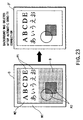
- FIG. 23 which includes a white band portion W1 having a density close to white in the periphery and characters having a background W2 surrounded thereby, as well as another background B having a color density deeper than the back ground W2.
- P1 and P2 in FIG. 23 respectively denote a character image and an image other than characters.
- the present invention has an object of providing an image processing method and an image processing apparatus, which are capable of deciding the kind of inputted image information with a high precision and are capable of automatically correcting the gradation of the inputted image information on real time.
- An image processing apparatus comprises a scanner mechanism for fetching an image, a function of preparing a density histogram on the basis of the fetched image, a decision function of deciding a sort of the fetched image corresponding to a histogram distribution of a background area when the density histogram is divided into the background area and a character area having an image density higher than the background area, and a first image density frequency having a maximum frequency within a range of the background area, and a circuit for correcting a gradation of the fetched image, in accordance with a decision result of the decision function.
- an image histogram is divided into two areas of a background area and a character area, and is analyzed in more details, depending on a distribution of a density histogram concerning the background area, thereby to decide the kind of image. Further, the kind of image is decided in consideration of a density value of the image density frequency of the maximum frequency in the background area and the frequency thereof.
- a very precise decision on areas can be made by making decisions on the areas in consideration of threshold values or the like depending on specific information, even if there are difficulties in making a simple decision as to whether an area is a photograph area or a character area. Therefore, it is possible to avoid such a trouble that a necessary background is deleted by erroneously deciding a photograph area as a character area.
- the method of the present invention realizes precise recognition concerning areas on the same grounds as described above.
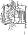
- FIG. 1 shows an internal structure of a digital copying machine as an example of an image processing apparatus according to the present invention.
- This digital copying machine is, for example, a composite type copying machine having three functions as a copying machine, a facsimile, and a printer.
- a reference 10 denotes an apparatus body which is internally provided with a scanner section 4 as an input means and a reading means as well as a printer section 6 as an output means and an image forming means.
- an original document mount stage 12 made of transparent glass on which an original document D is set as a target object to be read.
- an automatic original document feed device 7 (which will be referred to as only ADF 7 hereinafter) for automatically feeding the original document D.
- the ADF 7 is arranged such that the ADF can be opened and closed with respect to the original mount stage 12, and also functions as an original document presser for pressing the original document D set on the original document mount stage 12 into tight contact therebetween.
- the ADF 7 comprises an original document tray 8 on which an original document D is set, an empty sensor 9 for detecting presence or absence of an original document, a pick-up roller 14 for picking up one after another of original documents D, a sheet feed roller 15 for conveying an original document D picked up, paired aligning rollers 16 for aligning the top end of the original document D, and a conveyer belt 18 provided so as to cover substantially the entire of the original document mount stage 12.
- a plurality of original documents set on the original tray 8 with their surfaces facing upwards are picked up, one after another, in an order from the last page thereof, and are aligned by the paired aligning rollers 16, also one after another. Thereafter, the original documents D are conveyed, one after another, to a predetermined position on the original document mount stage 12 by the conveyer belt 18.
- a second carriage 28 movable in parallel with the original document mount stage 12 is provided below the original document mount stage 12.
- Second and third mirrors 30 and 31 for reflecting successively reflection light reflected by the original document D are installed on the second carrier such that the mirrors are perpendicular to each other.
- the second carriage 28 is moved so as to follow the first carriage 27 by a toothed belt or the like for driving the first carriage 27 and is moved in parallel with the original document mount stage 12 at a speed of 1/2 of the first carriage.
- a printer section 6 comprises a laser exposure device 40 as a latent image forming means.
- the laser exposure device 40 comprises a semiconductor laser oscillator 41 as a light source, a polygon mirror 36 as a scanning member for sequentially deflecting a laser beam injected from the semiconductor laser oscillator 41, a polygon motor 37 as a scanning motor for rotating and driving the polygon mirror 36 at a predetermined rotation speed described later, and an optical system 42 for deflecting and introducing the laser beam from the polygon mirror 36 to a photosensitive drum 44 also described later.
- a laser exposure device 40 constructed in a structure as described above is fixed and supported on a support frame of the apparatus body 10, not shown.
- the semiconductor laser oscillator 41 is controlled to be turned on and off in accordance with image information read from an original document D by the scanner section 4 or in accordance with facsimile transmission character information, and a laser beam from the oscillator 41 is directed to a photosensitive drum 44 by a polygon mirror 36 and an optical system 42.
- the circumferential surface of the photosensitive drum 44 is exposed to and scanned by the laser beam, thereby forming an electrostatic latent image.
- the printer section 6 has a rotatable photosensitive drum 44 as an image carrier which is provided in the substantial center of the apparatus body 10, and the circumferential surface of the photosensitive drum 44 is exposed and scanned with a laser beam from a laser exposure device 40, thereby to form an electrostatic latent image.
- an electrification charger 45 for electrifying the circumferential surface of the photosensitive drum 44 to a predetermined electric charge, a developer 46 as a developing means for supplying a toner as a developing agent onto an electrostatic latent image formed on the photosensitive drum 44 thereby to perform a development with a desired image density, a separation charger 47 for separating a paper sheet P as a medium on which an image is formed and which is supplied by a sheet feed cassette, from the photosensitive drum, a transfer charger 48 for transferring a toner image formed on the photosensitive drum 44 to a paper sheet P, a separation nail 49 for separating a paper sheet from the circumferential surface of the photosensitive drum 44, a cleaning device 50 for cleaning a toner remaining on the circumferential surface of the photosensitive drum 44, and a discharger 51 for discharging charges from the circumferential surface, in this order.
- a convey path 58 is formed which extends through a transfer section positioned between the photosensitive drum 44 and the transfer charger 48 from the sheet feed cassettes 52 to 54 and the large capacity feeder 55.
- a fixing device 60 having a fixing lamp 60a is provided at an end of the convey path 58.
- An feed-out port 61 is formed in the side wall of the apparatus body 10 opposite to the fixing device 60 and the feed-out port 61 is equipped with a finisher of a single tray.
- Pick-up rollers 63 are respectively provided near the upper sheet feed cassette 52, the middle sheet feed cassette 53, the lower sheet feed cassette 54, the sheet feed cassette 57, and the large capacity feeder 55, and each of the pick-up rollers 63 picks up paper sheets P, one after another, from corresponding one of the sheet feed cassette 52, 53, 54, and 57 and the large capacity feeder 55.
- the convey path 58 is provided with a plurality of pairs of sheet feed rollers 64 each pair of which convey a paper sheet P picked up by a pick-up roller 63.
- a pair of resist rollers 65 are provided in the upstream side of the convey path 58 with respect to the photosensitive drum 44.
- the pair of resist rollers 65 correct an inclination of a paper sheet P picked up, align the top end of the paper sheet P with the top end of a toner image on the photosensitive drum 44, and feed the paper sheet P to the transfer section at the same speed as the moving speed of the circumferential surface of the photosensitive drum 44.
- an aligning pre-sensor 66 is provided for detecting an arrival of the paper sheet P.
- Paper sheets P picked up by a pick-up roller 63 from one of the sheet feed cassettes 52 to 54 and 57 and the large capacity feeder 55 are fed to the pair of resist rollers 65 by the pair of sheet feed rollers 64. Every paper sheet P is subjected to an alignment of its top end by the resist rollers 65 and is thereafter fed to the transfer section.
- a developer image formed on the photosensitive drum 44 i.e., a toner image is transferred onto a paper sheet P by the transfer charger 48.
- the paper sheet P onto which the toner image has been transferred is separated off from the circumferential surface of the photosensitive drum 44 by operation of the separation charger 47 and the separation nail 49, and is conveyed to the fixing device 60 by a conveyer belt 67 forming part of the convey path 52. Further, the developer image is melted and fixed onto the paper sheet P, and thereafter, the paper sheet P is fed out onto a finisher 150 through a feed-out port 61 by the pair of sheet feed rollers 68 and the pair of feed-out rollers 69.
- an automatic double side device 70 for reversing the paper sheet P which has passed through the fixing device 60 and for feeding the sheet P again to the pair of the resist rollers 65 is provided below the convey path 58.
- the automatic double side device 70 comprises a temporary stock section 71 for temporarily stocking paper sheets P, a reverse path 72 branched from the convey path 58 to reverse a paper sheet P which has passed through the fixing device 60 and to guide the paper sheet to the temporary stock section 71, a pick-up roller 73 for picking up one after another of paper sheets P stocked in the temporary stock section 71, and a sheet feed roller 75 for feeding a picked up paper sheet P to a pair of resist rollers 65 through a convey path 74.
- a distribution gate 76 for selectively distribute paper sheets P to the feed-out port 61 or the reverse path 72.
- a paper sheet P which has passed through the fixing device 60 is fed to the reverse path 72 by the distribution gate 72 and is compiled and temporarily compiled at the temporary stock section 71. Thereafter, the paper sheet P is fed to the pair of resist rollers 65 through the convey path 74 by the pick-up roller 73 and the pair of sheet feed rollers 75. Further, the paper sheet P is aligned by the pair of resist rollers 65 and is thereafter fed to a transfer section where a toner image is transferred onto the back surface of the paper sheet P. Subsequently, the paper sheet P is fed out to the finisher 150 through the convey path 58, the fixing device 60, and the feed out roller 69.
- the finisher 150 serves to staple a set of documents fed out in units of sets. Every time when a paper sheet P to be stapled is fed out from the feed out port 61, the paper sheet P is aligned so as to match with the side where stapling is performed. After all the paper sheets P are fed out, a sheet press arm 152 presses a unit set of paper sheets P fed out, and a stapler unit (not shown) carries out stapling.
- a guide bar 151 moves down and paper sheets P stapled are fed out, in units of sets, onto a finisher feed out tray 154 by a finisher feed out roller 155.
- the amount by which the finisher feed out tray 154 moves down is decided to some extent by the number of paper sheets P to be fed out, and moves down by one step every time when a set of paper sheets are fed out.
- the guide bar 151 for aligning paper sheets P to be fed out is positioned at a height at which the guide bar 151 does not have a contact with paper sheets P stapled already and put on the finisher feed out tray 154.
- the finisher feed out tray 154 is connected to a shift mechanism (not shown) for shifting every set of paper sheets (for example, in the four directions of forward, backward, leftward, and rightward directions).
- an upper portion of the apparatus body 10 is provided with an operation panel 80 (not shown) for inputting a copy start command for starting various copy conditions and copy operations and for displaying a operating state.
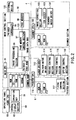
- FIG. 2 is a block diagram schematically showing electric connections in the digital copying machine shown in FIG. 1 and flows of signals thereof.
- a control system consists of three CPUs (Central Processing Units), i.e., a main CPU 91 in a main control section 90, a scanner CPU 100 of a scanner section 4, and a printer CPU 110 of a printer section 6.
- CPUs Central Processing Units
- the main CPU 91 serves to perform a bi-directional communication, and the main CPU 91 generates operation instructions while the printer CPU 110 returns a status.
- the printer CPU 119 and the scanner CPU 100 execute serial communications and the printer CPU generates an operation instruction while the scanner CPU 100 returns a status.
- the main CPU 91 manages total control.
- the ROM 92 stores control programs or the like.
- the RAM 93 temporarily stores information.
- the NVRAM (Non-Volatile RAM) 94 is a non-volatile memory backed up by a battery (not shown) and maintains stored data when the power is cut off.
- the common RAM 95 is used to perform a bidirectional communication between the main CPU 91 and the printer CPU 110.
- the page memory control section 97 stores and reads image information with respect to the page memory 98.
- the page memory 98 has an area capable of storing image information equivalent to a plurality of pages and is formed to be capable of storing data obtained by compressing image information from the scanner section 4 in units of pages.
- the printer font ROM 121 stores font data corresponding to print data.
- the printer control 99 serves to develop the print data from an external device such as a personal computer or the like, in form of image data at a resolution corresponding to data representing a resolution applied to printing data, with use of font data stored in the printer font ROM 121.
- the scanner section 4 consists of a scanner CPU 100 which manages total control, a ROM 101 storing control programs or the like, a RAM 102 for storing data, a CCD driver 103 for driving a line sensor 34, a scanner motor driver 104 for controlling rotation of a scanner motor for moving an exposure lamp 25 and mirrors 26, 27, and 28 or the like, and an image correcting section 105.
- the image correcting section 105 consists of an A/D converter circuit for converting an analogue signal from the line sensor 34 into a digital signal, a shading correcting circuit for correcting changes of a threshold level with respect to an output signal from the line sensor 34, caused by the variance of the line sensor 34 or environmental temperature changes, and a line memory for temporarily storing a digital signal subjected to a shading correction from the shading correcting circuit.
- the printer section 6 consists of a printer CPU 110 for managing total control, a ROM 111 storing control programs or the like, a RAM 112 for storing data, a laser driver 113 for driving a semiconductor laser oscillator 41, a polygon motor driver 114 for driving the polygon motor 27 of the laser exposure device 40, a feeding control section 115 for controlling feeding of paper sheets P through the convey path 58, a process control section 116 for controlling the process of charging, developing, and transferring with use of an electrification charger 45, a developing device 46, and a transfer charger 48, a fixing control section 117 for controlling the fixing device 60, and an option control section 118 for controlling options.
- a printer CPU 110 for managing total control
- ROM 111 storing control programs or the like
- RAM 112 for storing data
- a laser driver 113 for driving a semiconductor laser oscillator 41
- a polygon motor driver 114 for driving the polygon motor 27 of the laser exposure device 40
- a feeding control section 115 for controlling feeding
- the image processing section 96 serves to perform various image processing with respect to image information read by the scanner section 4, and for example, consists of a range correcting circuit 961, an image quality improving circuit 962, an expansion/reduction circuit 963, a gradation processing circuit 964, a timing signal generating section 965, and a clock generating section 966.
- the range correcting circuit 961 corrects the range of a density with respect to image information inputted, as will be specifically described later.
- the image quality improving circuit 962 performs image quality improving processing with respect to image information from the range correcting circuit 961.
- the expansion/reduction circuit 963 performs expansion/reduction processing on image information from the image quality improving circuit 962, whose image quality has been improved.
- the gradation processing circuit 964 performs gradation processing on image information from the expansion/reduction circuit 963.
- the timing signal generating section 965 generates various timing signals and supplies the timing signals to the range correcting circuit 961, the image quality improving circuit 962, the expansion/reduction circuit 963, and the gradation processing circuit 964.
- the clock generating section 966 generates various clock signals and supplies the clock signals to the range correcting circuit 961, the image quality improving circuit 962, the expansion/reduction circuit 963, the gradation processing circuit 964, and the timing signal generating section 965.
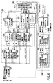
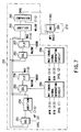
- FIG. 4 shows a structure of the range correcting circuit 961 in details.
- the range correcting circuit 961 consists of a histogram forming section 201 as a histogram forming means for preparing a density histogram from image information supplied from the scanner section 4, a peak position detecting section 202 as a peak position detecting means, an image sort deciding section 203 as an image sort deciding means, a reference value calculating section 204 as a reference value calculating means, a reset deciding section 205, a reference value selecting section 206 as a reference value selecting means, and a range correcting section 207 as a gradation correcting means.
- the peak position detecting section 202 serves to detect two peak positions of a density histogram formed by the histogram forming section and consists of a white peak position detector 208 and a black peak position detector 209.
- the white peak position detector 208 detects a position of a white peak from a density histogram formed by the histogram forming section 201 and the black peak position detector 209 detects a position of a black peak from a density histogram formed by the histogram forming section 201.
- the image sort deciding section 203 decides whether inputted image information is a character image or a photograph image, and consists of a white width deciding section 210, a character frequency deciding section 211, a white background deciding section 212, and an image sort deciding section 213.
- the white width deciding section 210 makes a temporary decision as to a sort of the document corresponding to a white width portion within an original document from a white peak position signal detected by the white peak position detector 208.
- the character frequency deciding section 211 makes a decision as to the character frequency in an original document, from a density histogram formed by the histogram forming section 201, a white peak position signal detected by the white peak position detector 208, and a black peak position signal detected by the black peak position detector 209.
- the white background deciding section 212 makes a temporary decision as to a sort of the document corresponding to a density histogram formed by the histogram forming section 201 and a white peak position signal detected by the white peak position detector 208.
- the image sort deciding section 213 decides the sort of inputted image information (or the kind of an original document), from a combination of a decision result of the white width deciding section 210, a decision result of the character frequency deciding section 211, and a decision result of the white background deciding section 212.
- the reference value calculating section 204 calculates reference values concerning white and black colors for making a gradation correction, on the basis of a density histogram formed by the histogram forming section 201 and a peak position detected by the peak position detecting section 202.
- the reference value correcting section 206 corrects a reference value from the reference value calculating section 204 on the basis of a decision result of the image sort deciding section 203, and consists of a reference value selecting section 214, a reference change value control section 215, and an error decision control section 216.
- the reference value selecting section 214 regards reference values calculated in the calculating section 204 or predetermined reference as white and black reference data, on the basis of an image sort decision result signal from the image sort deciding section 213.
- the reference change value control section 215 controls a change value of white and black reference values selected by the reference value selecting section 214.
- the error decision control section 216 restricts an error decision with respect to white and black reference values from the reference change value control section 215.
- the range correcting section 207 makes a range correction with respect to inputted image information with use of white and black reference values corrected by the reference value correcting section 206.
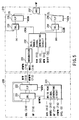
- FIG. 5 shows an example of a specific circuit structure of a white peak position detector 208 and a white width deciding section 210.
- the white peak position detector 208 consists of an integration circuit 231, a CR/CL enable signal generating circuit 232, selectors 233 and 234, flip-flop circuits 235 and 236, and a AND circuit 237, and decides a white width portion from an inputted white peak position signal MFW and a histogram HF, thereby to output a decision result signal MFH.
- FIG. 6 shows a specific example of a circuit configuration of a black peak position detector 209.
- the black peak position detector 209 consists of selectors 241, 242, and 243, flip-flop circuits 244 and 245, temporary black peak enable signal generators 246 and 247, an integration circuit 248, and a OR circuit 249, and outputs a black peak position signal MFB from an inputted density histogram HF.
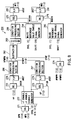
- FIG. 7 shows an example of a specific circuit configuration of the character frequency deciding section 211 and the image sort deciding section 213.
- the character frequency deciding section 211 consists of selectors 251, 252, and 253, addition circuits 254 and 255, flip-flop circuits 256 and 257, a WA1 enable signal generating circuit 258, a WA2 enable signal generating circuit 259, and a comparison circuit 260, and decides the character frequency from a white peak position signal MFW, a black peak position signal MFG, and a density histogram HF inputted, thereby to output a decision result signal CHDS.
- the image sort deciding section 213 consists of a AND circuit 261 and outputs a decision result signal DSC concerning the image sort, from a character frequency decision result signal CHDS, a white width decision result signal MFH, and a white background decision result signal DSC3.
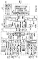
- FIG. 8 shows a specific example of a circuit configuration of the reference value calculating section 204.
- the reference value calculating section 204 consists of selectors 271, 272, 273, 274, 275, and 276, -1 enable/-1 enable signal generator 277, flip-flop circuits 278, 279, 280, and 281, a subtraction circuit 282, a division circuit 283, a white reference value enable signal generator 284, a black reference value enable signal generator 285, and condition processing sections 286, 287, and 288.
- the reference value calculating section 204 calculates white and black reference values from a white peak position signal MFW, a black peak position signal MFB, and a density histogram HF inputted, and outputs a white reference value signal MID and a black reference signal MAD.
- FIG. 9 shows a specific example of a circuit configuration of a reset deciding section 205.
- the reset deciding section 205 consists of a sub-scanning non-image section processor 291, a sub-scanning image section processor 292, a first-line processor 293, a timing generator 294, a selector 295, and a AND circuit 296, and outputs a reset signal CRST to the histogram forming section 201 in correspondence with a vertical synchronous signal VDEN.
- FIG. 10 shows a specific example of a circuit configuration of the reference value selecting section 214, the reference change value control section 215, the error decision control section 216, and the range correcting section 207.
- the reference value selecting section 214 consists of addition circuits 301 and 302, selectors 303 and 304, OR circuits 305 and 306, flip-flop circuits 307 and 308, and MD1 latch signal generator 309, and outputs a white reference value signal MID and a black reference value signal MAD from an image sort decision result signal DSC, a white reference value signal MID, and a black reference signal MAD.
- the reference change value control section 215 consists of comparison circuits 311 and 312, selectors 313, 314, 315, and 316, and a MD select signal generator 317, and outputs a white reference value signal MID 2 and a black reference value signal MAD2 obtained by controlling the change values of a white reference value signal MID1 and a black reference value signal MAD1 inputted.
- the error decision control section 216 consists of selectors 321 and 322, flip-flop circuits 323 and 324, a MD3 select signal generator 325, and a MD3 latch signal generator 326, and outputs a white reference value signal MID 3 and a black reference signal MAD3 obtained by restricting erroneous decisions of a white reference value signal MID2 and a black reference value signal MAD2 inputted.
- the range correcting section 207 consists of subtraction circuits 331 and 332, a division circuit 333, and condition processing sections 334 and 335, and outputs image information IDT0 subjected to a range correction, from an inputted white reference value signal MID3, an inputted black reference value signal MAD3, and image information IDT delayed by one line by a line buffer not shown, supplied from the scanner section 4.
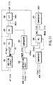
- FIG. 11 shows a specific circuit configuration of a white background deciding section 212.
- the white background deciding section 212 consists of an addition circuit 341, a subtraction circuit 342, comparators 343, 344, and 345, a flip-flop circuit 346, and selectors 347, 348, and 349.
- the addition circuit 341 adds a density histogram and an output BIF of the flip-flop circuit 346 together, and outputs a result KMF thereof.
- the selector 347 selects an addition result KMF or a constant FF (hex) by a carrier CO outputted from the adder circuit 341.
- the subtraction circuit 342 subtracts a constant 3 (hex) from a white peak position signal MFW, and outputs a result KMFW thereof.
- the comparator 343 compares the subtraction result KMFW with a constant 0 (hex) and sends a result of the comparison to the selector 348.
- the output of the comparator 343 is a value representing the number of density histograms HF to be added.
- the selector 348 switches either the output of the selector 347 or the output BIF of the flip-flop circuit 346 which should be outputted, by means of an output of the comparator 343.
- the selector 348 always selects the value of the output BIF of the flip-flop circuit 346 without selecting the output value of the selector 347.
- the output of the selector 348 is maintained by the flip-flop circuit 346.
- the comparator 344 compares a white peak position signal MFW with a constant 3 (hex), and sends a result thereof to the selector 349.
- the selector 349 switches either the output BIF of the flip-flop circuit 346 or the constant 0 (hex) which should be outputted, by means of an output of the comparator 344.
- the output WA3 of the selector 349 is the histogram frequency in the side much whiter than a white peak position.
- the output WA3 is compared with a WBASE by the comparator 345, and a white background decision result DSC3 is outputted.
- the WBASE described above is a value obtained from a white position signal MFW, a density histogram density HF[MFW] at this time, and a threshold value previously given.
- the histogram forming section 201 receives digital image information read out from an original document D by the scanner section 4 and digitized into multi-value 8-bit data. From the image information, the histogram forming section 201 prepares a density histogram in which the lateral axis expresses a density and the longitudinal axis expresses an appearance frequency at the density, and outputs a density histogram signal.
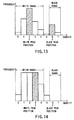
- FIG. 13 shows an example of a density histogram where the multi-value of image information is set to "8".
- the peak position detecting section 202 detects two peak positions.
- shapes of density histograms can roughly be divided into the following three cases.
- FIG. 14 shows a density histogram where the multi-value is 8 and only one peak is included. Two peaks, i.e., one for the side of white and the other for the side of black should be decided, and therefore, a range from which a peak in the side of white is searched and another range from which a peak in the side of black is searched are previously determined.
- "0" to "4" are the white range while "5" to "8" are the black range.
- a peak exists in the side of white.
- a peak position is detected in the same manner as in the case of "including two peaks".
- a peak position is that which satisfies conditions previously given. An example of the conditions will be "the crest having the highest density”, “the crest having the lowest density”, “the crest in the middle of the scanning density range", or the like.
- one peak position can be decided for each of the sides of white and black, even if no peak is recognized, i.e., even if only a crest having a frequency "0" exists or crests have an equal frequency in the scanning density range.
- the white peak position is "3" and the black peak position is "6".
- FIG. 13 shows a density histogram in case where the multi-value is 8 and two peaks are included. Two peaks, i.e., one in the side of white and the other in the side of black must be decided for, and therefore, a range from which a peak in the side of white should be searched and another range from which a peak in the side of black should be searched are previously given.
- peaks i.e., one in the side of white and the other in the side of black must be decided for, and therefore, a range from which a peak in the side of white should be searched and another range from which a peak in the side of black should be searched are previously given.
- FIG. 13 it is supposed that "0" to "4" are the white range while "6" to "7" are the black range. Those that satisfy conditions previously given among these ranges are regarded as peak positions.
- Examples of the conditions will be "the one which has the n-th highest frequency within a scanning density range", “the crest adjacent in the right side to the crest having the highest frequency within a scanning density range”, “the crest adjacent in the left side to the crest having the highest frequency in a scanning density range”, “the crest having the frequency closest to n% of the frequency of the crest having the highest frequency in a scanning density range”, and the like.
- One or a combination of the above conditions is used to detect peak positions. Note that a case in which a plurality of crests have an equal frequency will be described later. Supposing that a condition that "the one which has the highest frequency in a scanning density range" is set for each of the sides of white and black in the density histogram shown in FIG. 13, the white peak position is "2" and the black peak position is "6".
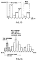
- FIG. 15 shows a density histogram where the multi-value is 8 and three peaks are included.
- Two peaks i.e., one in the side of white and the other in the side of black must be decided, and therefore, a range from which a peak in the side of white should be searched and another range from which a peak in the side of black should be searched are previously given.
- FIG. 15 it is supposed that "0" to "4" are the white range while “6" to "7" are the side of black range and three crests which can be regarded as peak positions are denoted by A, B, and C in an order from the crest having the smallest density among them.
- the peak position is obtained in the same manner as in the case of including two peaks. If a plurality of peaks are included in a scanning density range, the one which satisfies conditions previously given is decided as the peak position. Examples of the conditions are "the crest having the n-th highest frequency", “the crest having the highest density”, “the crest having the lowest density”, “the crest having the highest frequency if the crest having the second highest frequency has a frequency of n% or less of the frequency of the crest having the highest frequency, and otherwise, the crest having a higher density", and the like.
- the one which satisfies conditions previously given is decided as the peak position if a plurality of crests have an equal frequency as shown in FIG. 14.
- Examples of the conditions are "the crest having the highest density among peak position candidates", “the crest having the lowest density among peak position candidates”, “the crest having the middle density among peak position candidates”, and the like.
- the white width deciding section 210 decides a white width portion of the original document D, from a density histogram prepared by the histogram forming section 201 and a white peak position signal detected by the white peak position detector 208.
- the crest having the highest frequency within a range decided as a background portion is a crest of "6".
- the frequency of the crest "6" is HF[6]
- n% of the frequency of the crest is the threshold value THR1, the following exists.
- THR1 HF[6] ⁇ n%
- This value is compared with the frequencies of the left and right threshold values THR in the periphery of the crest "6" having the highest frequency.
- the original document is decided as a character original document if there is at least one crest having a frequency smaller than the threshold value THR1 in each of the left and right sides among the above crests. Specifically, the original document is decided as a character original document where the following condition is satisfied.
- a character original document in case of a character original document, the peak of a background rises and falls within a narrow range, and therefore, there must be a sharp fall of the frequency among a few crests in the left and right sides of the crest having the highest frequency (in FIG. 17).
- a photograph original document includes little background portions and includes many portions having intermediate frequencies, so that there is a high possibility that a few crests in the left and right sides of the crest having the highest frequency have frequencies substantially equal to or slightly smaller than the frequency of the crest having the highest frequency (as shown in FIG. 18).
- a character original document can be compared with a photograph original document by the condition described above.
- the character frequency deciding section 211 decides the character frequency within an original document D, from a density histogram prepared by the histogram forming section 201, a white peak position signal detected by the white peak position detector 208, and a black peak position signal detected by the black peak position detector 209.
- a decision concerning a character frequency is carried out as follows, taking into consideration that the ratio of a background portion and a character portion to the entire portion is large when an original document is a character original document. Specifically, an output MFW of the white peak position detector 208 and an output MFB of the black peak position detector 209 are used to obtain a sum of frequencies of the back ground portion and the character portion, which is compared with m% of the total frequency.
- the white background deciding section 212 decides a white background amount within an original document, from a density histogram prepared by the histogram forming section 201 and a white peak position signal detected by the white peak position detector 208.
- the threshold value 1 is a background density position corresponding to white whose background should naturally be considered to be outputted in color of white.
- WA3 HF[4] + HF[3] + HF[2] + HF[1] WA3 indicates how many frequencies exist in a portion whiter than the crest decided as a background.
- the WA3 is compared with the threshold value 3 and a decision is made as follows.
- the image sort deciding section 213 decides the sort of inputted image information (or the type of an original document), from a decision result of the white width deciding section 210, a decision result of the character frequency deciding section 211, and a decision result of the white background deciding section 212.
- DSC 1 (meaning a character original document) is outputted if all the three inputs are "1”
- DSC 0 (meaning a photograph original document) is outputted if any of three inputs is "0”.
- the reference value calculating section 204 calculates a reference value, from a peak position signal detected by the peak position detecting section 202, as described before, and a density histogram signal prepared by the histogram preparation 201. Both of the white and black reference values are obtained by same calculation formulas.
- FIG. 20 shows a peak position of a density histogram and frequencies of crests in the left and right side of the peak position.
- P denotes a peak position (or density)
- P - 1 and P + 1 respectively denote frequencies of crests in the left and right side of the peak position P.
- H[P], H[P - 1], H[P + 1] are respectively frequencies of P, P - 1, and P + 1.
- H[P - 1] or H[P + 1] H[P]
- K P ⁇ (Density width of a crest) + (Density width of a crest) ⁇ 1/2 + (H[P - 1] - H[P - 1]) / H[P] ⁇ ⁇ (Density width of a crest) ⁇ 1/2 ⁇
- the white and black reference values are respectively denoted as Kw and Kb.
- the reference value calculating section 204 calculates a reference value and outputs a reference value signal.
- the value of a reference value signal outputted from the reference value calculating section 204 is calculated for every period previously given. Therefore, a new reference value K(n) is decided for every period.
- the reference value correcting section 206 corrects a reference value signal from the reference value calculating section 204 because unevenness tends to easily appear in an output image after a gradation correction if a reference value once corrected by an offset constant changes for every predetermined period.
- the error decision control section 216 further corrects the reference value. The method of correcting the reference value will be explained in details below.
- the reference value selecting section 214 performs selection processing concerning reference values. Specifically, a reference value K is corrected with use of an image sort decision result signal from the image sort deciding section 203, a reference value signal from the reference value calculating section 204, a photograph image reference value constant previously given, a reference change value constant, and an offset constant. In the following, the correction method will be explained.
- K' is changed with use of a result of an image sort decision result signal outputted from the image sort deciding section 203.
- the reference change value control section 215 controls the change value of the reference value.
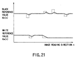
- FIG. 21 shows changes of the white reference value Kw(n) and the black reference value Kb(n) calculated for every predetermined period.
- a broken line indicates pre-correction changes and a continuous line indicates post-correction changes.
- Reference values should preferably change smoothly as indicated by the continuous line in FIG. 21, in order to restrict sharp density changes of an output image. Therefore, the reference change value control section 215 controls the characteristic of the broken line in FIG. 21 so as to match with the characteristic of the continuous line. In the following, the correction method will be explained.
- K(n - 1) decided for a preceding cycle is compared with K(n).
- K(n) K(n - 1) - Reference change value constant
- K'(n) K(n - 1) - Reference change value constant
- K(n) > K(n - 1) + Reference change value constant
- K'(n) K(n - 1) + Reference change value constant
- K(n - 1) - Reference change value constant
- K(n - 1) - Reference change value constant ⁇ K(n) ⁇ K(n - 1) + Reference change value constant
- K'(n) K(n)
- the error decision control section 216 performs restriction processing concerning an erroneous decision. Specifically, the section 216 counts how long a "character” or a "photograph” as a result of an image sort decision result signal from the image sort deciding section continues, thereby to further correct a reference value.
- this processing prevents a decision result being erroneously recognized. For example, if an area decision concerning a photograph area is made after an area decision on an original document to be recognized was once made as deciding a character area, the corresponding area is immediately decided as a photograph area and correction processing is not performed. For example, in this processing, the reference value is corrected when an original document area is kept continuously decided as a photograph area for about 10 mm (which can be set to an appropriate value by setting).
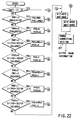
- FIG. 22 is a flowchart showing the operation of the correction processing. Note that the operation of this correction processing will be explained with reference to the reference symbols cited below.
- reg10[3] 1
- priorities are given to the following eight processing steps in this order and any of them is carried out.
- the reference value correcting section 206 outputs a reference value thus corrected, as a reference value signal after correction.
- the range correcting section 207 performs a gradation correction on image information with use of a reference value signal after correction, as an output from the reference value correcting section 206.
- the range correcting section 207 makes a linear correction on a width of 0 to FF (hex), from the white reference value Kw(n) and the black reference value Kb(n) obtained, in case where the multi-value level is 8-bit.
- the range correcting section 207 subjects image information to a gradation correction in accordance with the following formula and outputs output image information.
- D' (D - Kw(n)) / (Kb(n) - Kw(n)) ⁇ FF(hex)
- reference values are calculated from a density histogram for every predetermined period and a gradation correction is performed with use of the values.
- the reset deciding section 205 makes a reset decision on the basis of a decision result from the character frequency deciding section 211 and a peak position detected by the peak position detecting section 202. If it is decided that resetting is needed, the histogram forming section 201 is reset.
- step S12 whether or not processing for one page is completed is decided. If not, the flow returns to the step S1 and the processing as described above is repeated. If completed, the operation is terminated.
- a density histogram is prepared from inputted image information and the sort of the inputted image information is decided from a distribution of background portions of an original document and an image density value having the greatest frequency within the range of the background portions, in the density histogram.
- the gradation of the inputted image information is corrected. It this manner, it is possible to provide an image processing method and an image processing apparatus which are capable of deciding the sort of inputted image information with a high precision and automatically correcting the gradation of the inputted image information on real time.
- a density histogram is prepared from inputted image information, and the sort of the inputted image information is decided from characteristics of the density histogram prepared.
- the sort of the inputted image information is also decided from a distribution of background portions of an original document and an image density value having the greatest frequency within the range of the background portions in the density histogram prepared.
Abstract
Description
and
MFW -
WA3 = 0

K'(n) = K(n - 1) - Reference change value constant
K'(n) = K(n - 1) + Reference change value constant
Where K(n - 1) - Reference change value constant ≦ K(n)
≦ K(n - 1) + Reference change value constant, K'(n) = K(n)
The initial values are PHO = 1, PHO1 = 0, and DSC0 = 1.
- DSC
- : Original decision result
- DSC0
- : Previous original document decision result
- PHO
- : Decision result counter
- PHO1
- : Decision result change flag
- KSTOP
- : Decision result counter threshold value
- reg10[3]
- : Reference value correction control register (No=0/Yes=1)
- MID0
- : Previous white reference value
- MAD0
- : Previous black reference value
- MID
- : White reference value before correction
- MAD
- : Black reference value after correction
- MID'
- : White reference value used for gradation correction
- MAD'
- : Black reference value used for gradation correction
and where reg10[3] = 0
Claims (14)
- An image processing apparatus characterized by comprising:means (4) for fetching an image;means (96, S1) for forming a density histogram, based on the fetched image;means (90, S4 to S7) for deciding a sort of the fetched image corresponding to a histogram distribution of a background area when the density histogram is divided into the background area, and a character area having an image density higher than the background area, and a first image density frequency having a maximum frequency within a range of the background area; andmeans (105, S8 to S12) for correcting a gradation of the fetched image, in accordance with a decision result of the deciding means.
- An image processing apparatus according to claim 1, characterized in that the deciding means includes deciding means (90, S4) for deciding the fetched image as a character image when at least one crest of a histogram having a frequency of a predetermined percentage or less of the first image density frequency of the background area exists in predetermined range of each of left and right sides of a crest having the first image density frequency, and for deciding the fetched image as a photograph image when not.
- An image processing apparatus according to claim 1, characterized in that the deciding means (96, S5) includes:means (96, S5) for obtaining the first image density frequency having a maximum frequency within a range of the background area, and the second image density frequency having a maximum frequency within a range of the character area; andmeans (96, S5) for deciding the fetched image as a character area when a total of a subtotal of frequencies of a predetermined number of image densities in left and right sides of a first crest having the first image density frequency and a subtotal of frequencies of a predetermined number of image densities in left and right sides of a crest having the second image density frequency is greater than a predetermined percentage of a frequency total of frequencies of the entire density histogram; andmeans (96, S5) for deciding the fetched image as a photograph area when the total is equal to or smaller than the predetermined percentage of the frequency total of the entire density histogram.
- An image processing apparatus according to claim 1, characterized in that the deciding means includes:means (96, S6) for calculating an accumulative frequency by summing frequencies of a histogram crest having a density lower by a predetermined second density value than a first image density value of the first image density frequency to a histogram crest having a minimum density value when the first image density value of the first image density frequency is greater than a predetermined first density value; andmeans (96, S6) for deciding the fetched image as a photograph image when the accumulative frequency is greater than a predetermined frequency, and for deciding the fetched image as a character image when the accumulative frequency is equal to or smaller than the predetermine frequency.
- An image processing apparatus according to claim 1, characterized in that the deciding means includes:first deciding means (94, S4) for deciding the fetched image as a character image when at least one crest of a histogram having a frequency of a predetermined percentage or less of a first crest having the first image density frequency of the background area exists in each of left and right sides of the first image density frequency, and for deciding the fetched image as a photograph image when not;means (96, S5) for obtaining the first image density frequency having a maximum frequency within a range of the background area, and a second image density frequency having a maximum frequency within a range of the character area;second deciding means (96, S5) for deciding the fetched image as a character area when a total of a subtotal of frequencies of a predetermined number of image densities in left and right sides of the first crest and a subtotal of frequencies of a predetermined number of image densities in left and right sides of a second crest having the second image density frequency is greater than a predetermined second percentage of a frequency total of frequencies of the entire density histogram, and for deciding the fetched image as a photograph area when the total is equal to or smaller than the predetermined second percentage of the frequency total of the entire density histogram;means (96, S6) for calculating an accumulative frequency by summing frequencies of a histogram crest having a density lower by a predetermined second density value than a first density value having the first image density frequency to a histogram crest having a minimum density value when the first image density value is greater than a predetermined first density value; andthird deciding means (96, S6) for deciding the fetched image as a photograph image when the accumulative frequency is greater than a predetermined frequency, and for deciding the fetched image as a character image when the accumulative frequency is equal to or smaller than the predetermine frequency;fourth deciding means (96, S7) for deciding the fetched image as a photograph image when any one of the first, second, and third deciding means decides the fetched image as a photograph image; andmeans (105, S8 to S12) for correcting a gradation of the fetched image accordance with a decision result of the fourth deciding means.
- An image processing apparatus according to claim 1, characterized in that the correcting means includes means (105, S8 to S12, FIG. 21) for correcting a gradation of the fetched image within a predetermined range of change value, in accordance with a decision result of the deciding means.
- An image processing apparatus according to claim 1, characterized in that the correcting means includes means (105, S8 to S12) for correcting a gradation of the fetched image, in correspondence with a second image sort different from a first image sort, after recognizing that a predetermined number of decisions of the second image sort are made continuously after the deciding means makes a decision of the first image sort.
- An image processing method characterized by comprising:a step (4) of fetching an image;a step (96, S1) of forming a density histogram, based on the fetched image;a step (90, S4 to S7) of deciding a sort of the fetched image corresponding to a histogram distribution of a background area when the density histogram is divided into the background area and a character area having an image density higher than the background area, and a first image density frequency having a maximum frequency within a range of the background area; anda step (105, S8 to S12) of correcting a gradation of the fetched image, in accordance with a decision result of the deciding step.
- An image processing method according to claim 8, characterized in that the deciding step includes a deciding step (90, S4) of deciding the fetched image as a character image when at least one crest of a histogram having a frequency of a predetermined percentage or less of the first image density frequency of the background area exists in predetermined range of each of left and right sides of a crest having the first image density frequency, and of deciding the fetched image as a photograph image when not.
- An image processing method according to claim 8, characterized in that the deciding step (96, S5) includes:a step (96, S5) of obtaining the first image density frequency having a maximum frequency within a range of the background area, and the second image density frequency having a maximum frequency within a range of the character area; anda step (96, S5) of deciding the fetched image as a character area when a total of a subtotal of frequencies of a predetermined number of image densities in left and right sides of a first crest having the first image density frequency and a subtotal of frequencies of a predetermined number of image densities in left and right sides of a second crest having the second image density frequency is greater than a predetermined percentage of a frequency total of frequencies of the entire density histogram; anda step (96, S5) of deciding the fetched image as a photograph area when the total is equal to or smaller than the predetermined percentage of the frequency total of the entire density histogram.
- An image processing method according to claim 8, characterized in that the deciding step includes:a step (96, S6) of calculating an accumulative frequency by summing frequencies of a histogram crest having a density lower by a predetermined second density value than a first image density value having the first image density frequency to a histogram crest having a minimum density value when the first image density value is greater than a predetermined first density value; anda step (96, S6) of deciding the fetched image as a photograph image when the accumulative frequency is greater than a predetermined frequency, and for deciding the fetched image as a character image when the accumulative frequency is equal to or smaller than the predetermine frequency.
- An image processing method according to claim 8, characterized in that the deciding step includes:a first deciding step (94, S4) of deciding the fetched image as a character image when at least one crest of a histogram having a frequency of a predetermined percentage or less of the first image density frequency of the background area exists in each of left and right sides of a first crest having the first image density frequency, and of deciding the fetched image as a photograph image when not;a step (96, S5) of obtaining the first image density frequency having a maximum frequency within a range of the background area, and a second image density frequency having a maximum frequency within a range of the character area;a second deciding step (96, S5) of deciding the fetched image as a character area when a total of a subtotal of frequencies of a predetermined number of image densities in left and right sides of the first crest and a subtotal of frequencies of a predetermined number of image densities in left and right sides of a second crest having the second image density frequency is greater than a predetermined second percentage of a frequency total of frequencies of the entire density histogram, and of deciding the fetched image as a photograph area when the total is equal to or smaller than the predetermined second percentage of the frequency total of the entire density histogram;a step (96, S6) of calculating an accumulative frequency by summing frequencies of a histogram crest having a density lower by a predetermined second density value than a density value of a first image density value having the first image density frequency to a histogram crest having a minimum density value when the first image density frequency is greater than a predetermined first density value; anda third deciding step (96, S6) of deciding the fetched image as a photograph image when the accumulative frequency is greater than a predetermined frequency, and for deciding the fetched image as a character image when the accumulative frequency is equal to or smaller than the predetermine frequency;a fourth deciding step (96, S7) for deciding the fetched image as a photograph image when any of the first, second, and third deciding steps decides the fetched image as a photograph image; anda step (105, S8 to S12) of correcting a gradation of the fetched image accordance with a decision result of the fourth deciding means.
- An image processing method according to claim 8, characterized in that the correcting step includes a step (105, S8 to S12, FIG. 21) of correcting a gradation of the fetched image within a predetermined range of change value, in accordance with a decision result of the deciding step.
- An image processing method according to claim 8, characterized in that the correcting step includes a step (105, S8 to S12) for correcting a gradation of the fetched image, in correspondence with a second image sort different from a first image sort, after recognizing that a predetermined number of decisions of the second image sort are made continuously after the deciding step makes a decision of the first image sort.
Applications Claiming Priority (3)
| Application Number | Priority Date | Filing Date | Title |
|---|---|---|---|
| JP31777496A JP3779400B2 (en) | 1996-11-28 | 1996-11-28 | Image processing method |
| JP31777496 | 1996-11-28 | ||
| JP317774/96 | 1996-11-28 |
Publications (3)
| Publication Number | Publication Date |
|---|---|
| EP0845716A2 true EP0845716A2 (en) | 1998-06-03 |
| EP0845716A3 EP0845716A3 (en) | 1998-09-23 |
| EP0845716B1 EP0845716B1 (en) | 2002-06-19 |
Family
ID=18091908
Family Applications (1)
| Application Number | Title | Priority Date | Filing Date |
|---|---|---|---|
| EP97120373A Expired - Lifetime EP0845716B1 (en) | 1996-11-28 | 1997-11-20 | Image processing apparatus having image area recognition function and image processing method |
Country Status (5)
| Country | Link |
|---|---|
| US (1) | US6028958A (en) |
| EP (1) | EP0845716B1 (en) |
| JP (1) | JP3779400B2 (en) |
| CN (1) | CN1146757C (en) |
| DE (1) | DE69713473T2 (en) |
Cited By (2)
| Publication number | Priority date | Publication date | Assignee | Title |
|---|---|---|---|---|
| EP1085747A1 (en) * | 1999-03-02 | 2001-03-21 | Seiko Epson Corporation | Image data background judging device, image data background judging method, and medium on which image data background judging control program is recorded |
| EP1684520A2 (en) | 2005-01-24 | 2006-07-26 | Kabushiki Kaisha Toshiba | Image compression method and image compression device |
Families Citing this family (19)
| Publication number | Priority date | Publication date | Assignee | Title |
|---|---|---|---|---|
| JP4097800B2 (en) | 1998-09-07 | 2008-06-11 | 株式会社東芝 | Image processing method and image processing apparatus |
| JP3325243B2 (en) | 1999-09-20 | 2002-09-17 | 京セラミタ株式会社 | Image processing device |
| US7262778B1 (en) * | 2000-02-11 | 2007-08-28 | Sony Corporation | Automatic color adjustment of a template design |
| US6993719B1 (en) | 2000-02-11 | 2006-01-31 | Sony Corporation | System and method for animated character photo-editing interface and cross-platform education icon |
| US7136528B2 (en) * | 2000-02-11 | 2006-11-14 | Sony Corporation | System and method for editing digital images |
| JP2001251507A (en) * | 2000-03-03 | 2001-09-14 | Fujitsu Ltd | Image processor |
| JP3885987B2 (en) * | 2000-05-18 | 2007-02-28 | 株式会社リコー | Image reading apparatus and image forming apparatus |
| JP4085580B2 (en) * | 2001-02-20 | 2008-05-14 | 富士ゼロックス株式会社 | Image processing device |
| US7058222B2 (en) * | 2001-12-20 | 2006-06-06 | Xerox Corporation | Automatic background detection of scanned documents |
| JP3898075B2 (en) * | 2002-03-18 | 2007-03-28 | 株式会社リコー | Image processing apparatus, image processing method, and recording medium |
| JP4126938B2 (en) * | 2002-03-22 | 2008-07-30 | セイコーエプソン株式会社 | Image processing apparatus and image output apparatus |
| JP2007067571A (en) * | 2005-08-29 | 2007-03-15 | Fujitsu Ltd | Image processing apparatus |
| JP4282081B2 (en) * | 2005-10-31 | 2009-06-17 | キヤノン株式会社 | Image processing apparatus and method |
| DE102006055587B4 (en) * | 2006-11-24 | 2008-12-11 | OCé PRINTING SYSTEMS GMBH | Method, computer program and printing system for trapping print data with a plurality of objects |
| JP5041583B2 (en) * | 2006-12-21 | 2012-10-03 | キヤノン株式会社 | Scanning optical apparatus and image forming apparatus |
| JP5152203B2 (en) * | 2008-01-24 | 2013-02-27 | 富士通株式会社 | Image processing apparatus, image processing method, image processing program, and image correction apparatus |
| JP5361624B2 (en) * | 2009-09-09 | 2013-12-04 | キヤノン株式会社 | Image processing apparatus, image processing method, and program |
| CN102455628B (en) * | 2010-10-29 | 2014-08-13 | 京瓷办公信息系统株式会社 | Image forming apparatus |
| JP5939154B2 (en) * | 2012-12-27 | 2016-06-22 | ブラザー工業株式会社 | Image processing apparatus and computer program |
Citations (3)
| Publication number | Priority date | Publication date | Assignee | Title |
|---|---|---|---|---|
| US4903145A (en) * | 1986-08-06 | 1990-02-20 | Canon Kabushiki Kaisha | Image quality control apparatus capable of density-correcting plural areas of different types |
| US4929979A (en) * | 1988-01-29 | 1990-05-29 | Konica Corporation | Method and apparatus for processing image |
| EP0557099A1 (en) * | 1992-02-21 | 1993-08-25 | Canon Kabushiki Kaisha | Image processing apparatus |
-
1996
- 1996-11-28 JP JP31777496A patent/JP3779400B2/en not_active Expired - Fee Related
-
1997
- 1997-11-20 DE DE69713473T patent/DE69713473T2/en not_active Expired - Lifetime
- 1997-11-20 EP EP97120373A patent/EP0845716B1/en not_active Expired - Lifetime
- 1997-11-26 US US08/979,857 patent/US6028958A/en not_active Expired - Lifetime
- 1997-11-27 CN CNB971230234A patent/CN1146757C/en not_active Expired - Fee Related
Patent Citations (3)
| Publication number | Priority date | Publication date | Assignee | Title |
|---|---|---|---|---|
| US4903145A (en) * | 1986-08-06 | 1990-02-20 | Canon Kabushiki Kaisha | Image quality control apparatus capable of density-correcting plural areas of different types |
| US4929979A (en) * | 1988-01-29 | 1990-05-29 | Konica Corporation | Method and apparatus for processing image |
| EP0557099A1 (en) * | 1992-02-21 | 1993-08-25 | Canon Kabushiki Kaisha | Image processing apparatus |
Cited By (5)
| Publication number | Priority date | Publication date | Assignee | Title |
|---|---|---|---|---|
| EP1085747A1 (en) * | 1999-03-02 | 2001-03-21 | Seiko Epson Corporation | Image data background judging device, image data background judging method, and medium on which image data background judging control program is recorded |
| EP1085747A4 (en) * | 1999-03-02 | 2004-06-30 | Seiko Epson Corp | Image data background judging device, image data background judging method, and medium on which image data background judging control program is recorded |
| US7099041B1 (en) | 1999-03-02 | 2006-08-29 | Seiko Epson Corporation | Image data background determining apparatus image data background determining method, and medium recording thereon image data background determination control program |
| EP1684520A2 (en) | 2005-01-24 | 2006-07-26 | Kabushiki Kaisha Toshiba | Image compression method and image compression device |
| EP1684520A3 (en) * | 2005-01-24 | 2008-12-31 | Kabushiki Kaisha Toshiba | Image compression method and image compression device |
Also Published As
| Publication number | Publication date |
|---|---|
| JPH10164368A (en) | 1998-06-19 |
| DE69713473T2 (en) | 2003-02-06 |
| CN1146757C (en) | 2004-04-21 |
| EP0845716A3 (en) | 1998-09-23 |
| JP3779400B2 (en) | 2006-05-24 |
| EP0845716B1 (en) | 2002-06-19 |
| CN1188261A (en) | 1998-07-22 |
| DE69713473D1 (en) | 2002-07-25 |
| US6028958A (en) | 2000-02-22 |
Similar Documents
| Publication | Publication Date | Title |
|---|---|---|
| EP0845716B1 (en) | Image processing apparatus having image area recognition function and image processing method | |
| US6504628B1 (en) | Color image-forming apparatus capable of discriminating the colors of the original image | |
| US6476847B2 (en) | Pulse width modulation system and image forming apparatus having the pulse width modulation system | |
| US6313924B2 (en) | Image forming apparatus and method of correcting the characteristic of each body by printing reference pattern in the machine and reading the printed pattern again | |
| JP2003319182A (en) | Image processing apparatus and image forming apparatus | |
| US5953450A (en) | Image forming apparatus correcting the density of image information according to the type of manuscript | |
| US5696595A (en) | Image forming apparatus with automatic density adjustment | |
| US6643397B1 (en) | Image processing method, image processing apparatus and image forming apparatus | |
| US6833926B1 (en) | Image processing apparatus | |
| JP3862789B2 (en) | Image processing apparatus, image processing method, and image forming apparatus | |
| US5748345A (en) | Image processing apparatus for performing image processing according to colors of input image | |
| US6525834B2 (en) | Image processing apparatus | |
| JP3912864B2 (en) | Image processing apparatus and image forming apparatus | |
| JP3974700B2 (en) | Image forming apparatus and image processing method | |
| EP0551823B1 (en) | Image processing apparatus | |
| EP0876052B1 (en) | An image forming apparatus and an image forming method thereof | |
| JP2965906B2 (en) | Image forming device | |
| JPH0969935A (en) | Image forming device | |
| JP3354681B2 (en) | Image forming device | |
| JP4237353B2 (en) | Image processing device | |
| JP3658396B2 (en) | Image recording apparatus and control method thereof | |
| JP3662697B2 (en) | Image reading apparatus, image forming apparatus, and image reading method | |
| JP2002077597A (en) | Image processing device | |
| JPH05300332A (en) | Picture reader | |
| JPH0686056A (en) | Picture processor |
Legal Events
| Date | Code | Title | Description |
|---|---|---|---|
| PUAI | Public reference made under article 153(3) epc to a published international application that has entered the european phase |
Free format text: ORIGINAL CODE: 0009012 |
|
| 17P | Request for examination filed |
Effective date: 19971120 |
|
| AK | Designated contracting states |
Kind code of ref document: A2 Designated state(s): DE FR GB |
|
| AX | Request for extension of the european patent |
Free format text: AL;LT;LV;MK;RO;SI |
|
| PUAL | Search report despatched |
Free format text: ORIGINAL CODE: 0009013 |
|
| RAP1 | Party data changed (applicant data changed or rights of an application transferred) |
Owner name: KABUSHIKI KAISHA TOSHIBA |
|
| K1C1 | Correction of patent application (title page) published |
Effective date: 19980603 |
|
| AK | Designated contracting states |
Kind code of ref document: A3 Designated state(s): AT BE CH DE DK ES FI FR GB GR IE IT LI LU MC NL PT SE |
|
| AX | Request for extension of the european patent |
Free format text: AL;LT;LV;MK;RO;SI |
|
| AKX | Designation fees paid |
Free format text: DE FR GB |
|
| RBV | Designated contracting states (corrected) |
Designated state(s): DE FR GB |
|
| 17Q | First examination report despatched |
Effective date: 20001117 |
|
| GRAG | Despatch of communication of intention to grant |
Free format text: ORIGINAL CODE: EPIDOS AGRA |
|
| GRAG | Despatch of communication of intention to grant |
Free format text: ORIGINAL CODE: EPIDOS AGRA |
|
| GRAH | Despatch of communication of intention to grant a patent |
Free format text: ORIGINAL CODE: EPIDOS IGRA |
|
| GRAH | Despatch of communication of intention to grant a patent |
Free format text: ORIGINAL CODE: EPIDOS IGRA |
|
| GRAA | (expected) grant |
Free format text: ORIGINAL CODE: 0009210 |
|
| AK | Designated contracting states |
Kind code of ref document: B1 Designated state(s): DE FR GB |
|
| REG | Reference to a national code |
Ref country code: GB Ref legal event code: FG4D |
|
| REF | Corresponds to: |
Ref document number: 69713473 Country of ref document: DE Date of ref document: 20020725 |
|
| ET | Fr: translation filed | ||
| PLBE | No opposition filed within time limit |
Free format text: ORIGINAL CODE: 0009261 |
|
| STAA | Information on the status of an ep patent application or granted ep patent |
Free format text: STATUS: NO OPPOSITION FILED WITHIN TIME LIMIT |
|
| 26N | No opposition filed |
Effective date: 20030320 |
|
| PGFP | Annual fee paid to national office [announced via postgrant information from national office to epo] |
Ref country code: DE Payment date: 20131113 Year of fee payment: 17 Ref country code: GB Payment date: 20131120 Year of fee payment: 17 |
|
| REG | Reference to a national code |
Ref country code: DE Ref legal event code: R119 Ref document number: 69713473 Country of ref document: DE |
|
| GBPC | Gb: european patent ceased through non-payment of renewal fee |
Effective date: 20141120 |
|
| REG | Reference to a national code |
Ref country code: FR Ref legal event code: PLFP Year of fee payment: 19 |
|
| PG25 | Lapsed in a contracting state [announced via postgrant information from national office to epo] |
Ref country code: GB Free format text: LAPSE BECAUSE OF NON-PAYMENT OF DUE FEES Effective date: 20141120 Ref country code: DE Free format text: LAPSE BECAUSE OF NON-PAYMENT OF DUE FEES Effective date: 20150602 |
|
| REG | Reference to a national code |
Ref country code: FR Ref legal event code: PLFP Year of fee payment: 20 |
|
| PGFP | Annual fee paid to national office [announced via postgrant information from national office to epo] |
Ref country code: FR Payment date: 20161014 Year of fee payment: 20 |