EP0845889A2 - Router for high-speed packet communication between terminal apparatuses in different LANs - Google Patents
Router for high-speed packet communication between terminal apparatuses in different LANs Download PDFInfo
- Publication number
- EP0845889A2 EP0845889A2 EP97120873A EP97120873A EP0845889A2 EP 0845889 A2 EP0845889 A2 EP 0845889A2 EP 97120873 A EP97120873 A EP 97120873A EP 97120873 A EP97120873 A EP 97120873A EP 0845889 A2 EP0845889 A2 EP 0845889A2
- Authority
- EP
- European Patent Office
- Prior art keywords
- packet
- router
- address
- destination
- routing
- Prior art date
- Legal status (The legal status is an assumption and is not a legal conclusion. Google has not performed a legal analysis and makes no representation as to the accuracy of the status listed.)
- Granted
Links
Images


Classifications
-
- H—ELECTRICITY
- H04—ELECTRIC COMMUNICATION TECHNIQUE
- H04L—TRANSMISSION OF DIGITAL INFORMATION, e.g. TELEGRAPHIC COMMUNICATION
- H04L61/00—Network arrangements, protocols or services for addressing or naming
- H04L61/09—Mapping addresses
- H04L61/10—Mapping addresses of different types
-
- H—ELECTRICITY
- H04—ELECTRIC COMMUNICATION TECHNIQUE
- H04L—TRANSMISSION OF DIGITAL INFORMATION, e.g. TELEGRAPHIC COMMUNICATION
- H04L61/00—Network arrangements, protocols or services for addressing or naming
Definitions
- the present invention relates to a router serving as an inter-LAN connection apparatus for connecting a plurality of LANs (Local Area Networks) and, more particularly, to a router for high-speed packet communication between terminal apparatuses in different LANs.
- LANs Local Area Networks
- a LAN is used as a communication network for communication between terminal apparatuses in a relatively small-size range such as one company or a limited area.
- routers As a technique of expanding such a network, a technique of connecting different LANs by using inter-LAN connection apparatuses called routers is used.
- a router is designed to perform network interconnection by converting the lower three layers of a total of seven layers of a reference OSI (Open System Interconnection) model, i.e., the three layers including the network layer and the subsequent layers.
- This router updates and outputs the data link layer address of a received packet so as to sequentially cause the address to approach the destination of the packet mainly on the basis of the destination address of the network layer of the received packet. Routing is performed in this manner.
- OSI Open System Interconnection
- IP Internet Protocol
- MAC media access control
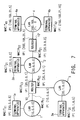
- FIG. 7 shows a communication network in which a plurality of LANs 1 to 4 are connected to each other through conventional routers 10 and 10'.
- network addresses are assigned to the LANs 1 to 4 in advance to identify the respective networks.
- IP addresses are assigned to terminal apparatuses 1a, ⁇ , 2a, ⁇ , 3a, ⁇ , 4a, ⁇ in the LANs 1 to 4 to identify the respective terminal apparatuses in accordance with the network addresses of the LANs to which the terminal apparatuses belong.
- Each terminal apparatus has a unique MAC address (generally having a six-octet length) registered in the apparatus manufacturing process.
- IP addresses are assigned to the interfaces of the routers 10 and 10' connected to the LANs 1 to 4 in correspondence with the network addresses of the LANs to which the interfaces are directly connected.
- MAC addresses are registered in units of interfaces.
- Each of the routers 10 and 10' includes two types of memory tables, i.e., a routing table and an ARP (address resolution protocol) table, to obtain an optimal route through which a packet received from a terminal apparatus in a LAN and addressed to a terminal apparatus in another LAN is to be transmitted to the destination LAN.
- ARP address resolution protocol
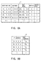
- FIGS. 8A and 8B respectively show a routing table 11 and an ARP table 12 of the router 10.
- the network addresses of the LANs 1 to 4 which the router 10 can connect are stored.
- IP address [20.0.0.2] of the interface of another router 10' with respect to the LAN 2 is stored in correspondence with the LAN 4 which is indirectly connected to the LAN 2 through the router 10'.
- net mask data (4-octet length) are stored. Each net mask data is used as a mask value when comparing the destination IP address of the received packet with the "DESTINATION" column of the routing table.
- interface numbers indicating the specific interfaces to be used for connection to the respective LANs are stored.
- the IP addresses and MAC addresses of the terminal apparatuses in the LANs 1 to 3 directly connected to the router 10 and the interface of another router 10', on the LAN 2 side, which is directly connected to the LAN 2, are stored in correspondence with each other.
- router 10' also includes two types of memory tables similar to those described above.
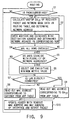
- FIG. 9 is a flow chart showing a procedure for routing performed by the router 10.
- the terminal apparatus 1a transmits a packet P1 in FIG. 10A onto the LAN 1.
- This packet P1 has a MAC header portion Ha, an IP header portion Hb, and data portions Da and FCS (Frame Check Sequence).
- the MAC address (R 11 ) of the router 10 to which the packet is directly transmitted is written as a destination MAC address DA MAC (to be simply referred to as DA MAC hereinafter), and the MAC address (T 11 ) of the terminal apparatus 1a itself is also written as a source MAC address SA MAC (to be simply referred to as SA MAC hereinafter).
- IP address [10.0.0.5] of the terminal apparatus 1a itself is written as a source IP address SA IP (to be simply referred to as SA IP hereinafter), and IP address [192.168.21.5] of the terminal apparatus 4a which is to finally receive the packet P1 is written as a destination IP address DA IP (to be simply referred to as DA IP hereinafter).
- SA IP source IP address
- DA IP destination IP address
- the router 10 receives the packet P1, in which the MAC address (R 11 ) of its interface is written as DA MAC , on the LAN 1, and calculates the AND of DA IP [192.168.21.5] of the packet P1 and each net mask data of the routing table 11. The router 10 then obtains the AND which coincides the network address in the corresponding row of the "DESTINATION" column (steps S1 to S4).
- network address [192.168.21.0] is uniquely determined by the AND of DA IP and net mask data [255.255.255.0] ("255" is 8-bit data consisting of only 1s; "0" is 8-bit data consisting of only 0s) in the fourth row of the table when viewed from the top.
- the router 10 obtains one of the network addresses which has the smallest metric value (steps S5 and S6).
- the router 10 then checks the presence/absence of a gateway address corresponding to this network address (step S7).
- the router 10 reads out the MAC address (R 21 ) corresponding to the gateway address from the ARP table 12 (step S8).
- the router 10 reads out the MAC address corresponding to DA IP of the packet received on the LAN 1 from the ARP table 12 (step S9).
- the router 10 updates DA MAC with the obtained MAC address (R 21 ), and outputs a packet P2 whose SA MAC is updated with the MAC address (R 13 ) of the interface of the router 10 itself, which is connected to the LAN 2, from the previously obtained interface to the LAN 2 (step S10).
- Routing processing similar to the routing processing performed by the router 10 is also performed by the router 10'.
- the router 10' receives the packet P2 on the LAN 2, and calculates the AND of DA IP [192.168.21.5] of the packet P2 and each mask data of the routing table of the router 10'. With this operation, the router 10' obtains network address [192.168.21.0] of the LAN 4 to which the terminal apparatus 4a belongs, and also obtains the interface to which the LAN 4 is connected.
- the router 10' reads out the MAC address (T 41 ) corresponding to DA IP [192.168.21.5] from the ARP table, and outputs a packet P3 whose MAC header portion Ha is updated with the readout MAC address (T 41 ) and the MAC address (R 22 ) of the router 10' to the LAN 4, as shown in FIG. 10C.
- the terminal apparatus 4a connected to the LAN 4 receives the packet P3 in which the MAC address (T 41 ) of the apparatus itself is written as DA MAC of the MAC header portion.
- IP address of an interface itself may be stored in the "GATEWAY" row of the routing table, instead of (0.0.0.0), to indicate the direct connection of the interface.
- the two types of memory tables are referred to twice every time a packet is received, and the routing table 11 is searched for an optimal route in consideration of net mask data and metric values. That is, complicated processing is required. For this reason, software processing is inevitably required, and hence high-speed routing processing cannot be realized.
- the routers for connecting such VLANs to each other cannot perform high-speed packet transmission even between terminal apparatuses in different VLANs which are located at a short distance from each other.
- an object of the present invention to provide a router serving as an inter-LAN connection apparatus which can perform high-speed routing based on the assumption that most of the packets flowing in LANs satisfy predetermined conditions.
- a router having a routing section for performing routing based on a routing table and an ARP (address resolution protocol) table to transmit a received packet to a destination and adapted to connect a plurality of local area networks (LANs), comprising:
- a router 20 serving as an inter-LAN connection apparatus has a plurality of interfaces 21a to 21c for connection to LANs and is designed to update the data link layer address of a packet received through one of the interfaces and output it to the nearest LAN so as to transmit the packet to the LAN to which the terminal apparatus corresponding to the network layer destination address of the packet belongs.
- the router 20 includes a memory table 23 in which the network layer addresses of the respective terminal apparatuses in LANs 1 to 3 directly connected to the above interfaces and the network layer addresses of the respective terminal apparatuses in a LAN 4 connected to the router 20 through another inter-LAN connection apparatus 20' are stored, together with the data link layer addresses of the terminal apparatuses in the LANs directly connected to the above interfaces, which are stored in correspondence with the network layer addresses, the data link layer address of another inter-LAN connection apparatus, which is stored in correspondence with the network layer addresses of the respective terminal apparatuses in the LAN connected to the router 20 through another inter-LAN connection apparatus, and pieces of designation information for designating the interfaces for directly transmitting packets to the terminal apparatuses having the stored data link layer addresses and another inter-LAN connection apparatus, which are stored in correspondence with the respective network layer addresses, a packet determination means 25 for comparing the respective data of the header portion of a received packet with corresponding predetermined values to check whether the received packet satisfies predetermined conditions, a
- FIG. 1 shows a communication network in which the LANs 1 to 4 are connected to each other through the routers 20 and 20'.
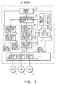
- FIG. 2 shows the arrangement of the router 20 (20').
- the arrangement of the communication network is the same as the conventional communication network shown in FIG. 7, and the addresses of the LANs 1 to 4 and the routers 20 and 20' are set in the same manner as described above.
- the router 20 includes an input/output section 21 for connection to the LANs 1 to 3, a routing table 11 and an ARP table 12 like those described above, a first routing section 22 for performing routing in the same manner as in the prior art by using these two memory tables, and forming/managing the memory table 23, the packet determination means 25 for checking whether a packet received through the input/output section 21 satisfies predetermined conditions, the registration determination means 29 for checking whether DA IP of the input packet is registered in the memory table 23, and the second routing section 30 designed for performing routing for only a packet which is determined by the packet determination means 25 as a packet satisfying the predetermined conditions and also determined by the registration determination means 29 as an already registered packet.
- the input/output section 21 includes a plurality of interfaces 21a, 21b, 21c, ⁇ for connection to a plurality of LANs 1, 2, 3, ⁇ .
- the interfaces 21a, 21b, 21c, ⁇ input packets whose DA MAC data coincide with the MAC addresses of the respective interfaces to the router 20 on the LANs to which the respective interfaces are connected, and output packets having undergone routing in the router 20 to the corresponding LANs 1, 2, 3, ⁇ .
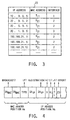
- the first routing section 22 performs routing for the packet input through the input/output section 21 by using the routing table 11 and the ARP table 12 in FIGS. 8A and 8B in the same manner as the conventional router, and also generates data like those stored in the memory table 23 in FIG. 3.
- IP addresses of all the terminal apparatuses 1a, ⁇ , 2a, ⁇ , 3a, ⁇ , 4a, ⁇ , which can be connected through the router 20 and the interface of the router 20' are stored in the "IP ADDRESS" column of the memory table 23 in FIG. 3.
- the MAC addresses of terminal apparatuses, of the terminal apparatuses having the IP addresses in the "IP ADDRESS" column, which belong to the LANs directly connected to the interfaces of the router 20 are written, together with the MAC address of the interface of the router 20' on the router 20 side, which is written in correspondence with a terminal apparatus, e.g., the terminal apparatus 4a, in the LAN 4 connected to the interface of the router 20 through another router 20'.
- Interface numbers indicating interfaces for transmitting packets to the terminal apparatuses 1a, ⁇ , 2a, ⁇ , 3a, ⁇ , 4a, ⁇ and the router 20' whose MAC addresses are written in the "MAC ADDRESS" column are written in the "INTERFACE” column.
- the optimal routes obtained by the conventional routing scheme executed by the first routing section 22 are registered in the memory table 23 in advance in correspondence with DA IP of received packets.
- the packet determination means 25 is constituted by a MAC frame checking circuit 26, an IP header checking circuit 27, and an error checking circuit 28.
- the packet determination means 25 checks whether a packet received through the input/output section 21 satisfies the predetermined conditions. As shown in FIG. 4, the packet determination means 25 performs the respective checks by comparing the data of a MAC header portion Ha and an IP header portion Hb of the packet with predetermined data.
- the MAC frame checking circuit 26 compares the TYPE information and DA MAC of the MAC header portion of a packet input through the input/output section 21 with predetermined data to check whether the packet complies with the IP of the LAN protocols, and is not a broadcast packet. With these checks, the MAC frame checking circuit 26 outputs packets (e.g., IPX and AppleTalk packets) other than IP packets and broadcast packets to the first routing section 22.
- packets e.g., IPX and AppleTalk packets
- the IP header checking circuit 27 checks a header length HL, version V, and TTL (Time to Live) value of the IP header portion of a packet. With this check, for example, the IP header checking circuit 27 outputs a packet whose header length HL is not "5", a packet whose version V is not "4", and a packet whose TTL value is "1" or less to the first routing section 22.
- a TTL value is used to prevent a given packet from entering a loop route in the process of propagation through a route to the final destination terminal apparatus, permanently existing on the network, and interfering with communication of other packets.
- the TTL value is decreased every time the packet passes through a router.
- the packet is discarded by the first routing section 22.
- the error checking circuit 28 performs an error check on the IP header portion of a packet on the basis of the check sum CS of the IP header portion. If there is an error, the packet is sent to the first routing section 22 to be processed.
- the registration determination means 29 checks whether DA IP of a packet which is determined by the packet determination means 25 as a packet satisfying the predetermined conditions is registered in the memory table 23. If DA IP is not registered, the registration determination means 29 outputs the packet to the first routing section 22.
- the second routing section 30 performs routing for the packet on the basis of the memory table 23.
- the second routing section 30 has an IP header updating circuit 31 and a MAC header updating circuit 32.
- the IP header updating circuit 31 decreases the TTL value of the IP header portion of the packet satisfying the predetermined conditions by a predetermined value, and updates the check sum CS in accordance with the decrease in the TTL value.
- the MAC header updating circuit 32 obtains the MAC address and the interface number which correspond to the DA IP of the packet satisfying the predetermined conditions from the memory table 23, and updates DA MAC of the packet with the obtained MAC address. In addition, the MAC header updating circuit 32 updates SA MAC with the MAC address corresponding to the obtained interface number, and outputs the packet from the corresponding interface.
- the respective circuits constituting the packet determination means 25, the registration determination means 29, and the routing section 30 need not execute complicated processing unlike the first routing section 22, and perform only comparison and rewrite operations mainly for data at predetermined bit positions of a packet.
- router 20 of the present invention since these circuits can be simply formed by using dedicated high-speed logic circuits, routing for a packet satisfying the predetermined conditions can be performed at a very high speed.
- router 20' has the same arrangement as that of the router 20 (the contents of the respective memory tables differ).
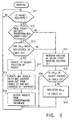
- FIG. 5 is a flow chart showing a procedure for processing performed by the router 20 (20').
- the router 20 receives this packet and causes the packet determination means 25 and the registration determination means 29 to check whether the packet satisfies the predetermined conditions and DA IP of the packet has already been registered in the memory table 23 (steps S11 to S13).
- the router 20 causes the routing section 30 to update the TTL value and check sum of the IP header portion of the packet, and reads out, from the memory table 23, the MAC address (R 21 ) and the interface number (2) which correspond to DA IP [192.168.21.5] determined by the registration determination means 29 as an already registered address.
- the router 20 outputs a packet P2, whose MAC header portion Ha is updated with the readout MAC address (R 21 ) and the MAC address (R 12 ) of the interface 21b, from the interface 21b corresponding to number 2 to the LAN 2 (steps S14 to S16).
- step S12 If it is determined in step S12 that the received packet does not satisfy the predetermined conditions, or DA IP has not been registered in the memory table 23, the router 20 causes the first routing section 22 to perform routing for the packet in the same manner as in the conventional routing scheme (step S17).
- the first routing section 22 updates the routing table 11 and the ARP table 12, as needed, and registers DA IP in the memory table 23 to reconstruct the memory table 23 if it has not been registered (steps S18 and S19).
- the router 20 of the present invention therefore, if, for example, DA IP of a received packet has not been registered in the memory table 23, and routing for the packet is performed by the first routing section 22, since the MAC address and the interface number which correspond to DA IP of the packet are registered in the memory table 23, the second routing section 30 can perform high-speed routing for the next packet addressed to the same destination.
- the packet P2 output from the router 20 to the LAN 2 is received by the router 20'.
- the router 20' performs the same processing as that performed by the router 20 to output a packet P3, whose MAC header portion Ha is updated with the MAC address (T 41 ) of the terminal apparatus 4a and the MAC address (R 22 ) of the router itself as shown in FIG. 10C, to the LAN 4.
- the terminal apparatus 4a receives this packet P3.
- each of the routers 20 and 20' uses the memory table 23, in which the MAC addresses and the interfaces which correspond to the optimal, nearest routes with respect to DA IP of packets are registered in advance, as well as the routing table 11 and the ARP table 12.
- each of the routers 20 and 20' includes the second routing section 30 designed specially for packets satisfying the predetermined conditions, i.e., most of the packets flowing on the LANs.
- Each of the routers 20 and 20' of this embodiment can greatly increase the packet transmission efficiency and cope with high-speed LANs as compared with the conventional technique of obtaining optimal routes for all packets by referring to the two types of memory tables, i.e., the routing table 11 and the ARP table 12.
- the router 20' which is connected to the router 20 through the LAN, has the same arrangement as that of the router 20.
- the router 20' may be a router for performing routing only by means of software as in the prior art.
- the first routing section 22 performs routing on the basis of the routing table 11 and the ARP table 12.
- a first routing section corresponding to a plurality of types of protocols including the IP may be used.
- the respective checking circuits 26 to 28 of the packet determination means 25 and the registration determination means 29 are connected in series. These circuits, however, may be connected in parallel in consideration of the differences between the periods of time taken to obtain the respective check and determination results.
- the checking circuits 26 to 28 may be arranged such that a MAC frame check and an IP header check, which require only comparison between packet data, are sequentially performed, while an error check requiring calculations is concurrently performed.
- these circuits may be arranged such that determination of registration with respect to a received packet and packet determination may be concurrently performed regardless of whether the packet satisfies the predetermined conditions.
- each router has a memory table 23' in which the "VLAN ID” column and the "PORT NUMBER” column are arranged in place of the "INTERFACE” column, and the ID numbers of the VLANs and the port numbers which correspond to the respective IP addresses are registered in advance.
- the packet whose MAC header portion has been updated by the second routing section 30 is sent to a terminal apparatus or another router through an interface section of the switching hub, together with the ID number of the corresponding VLAN and the port number.
- the packet addressed to the terminal apparatus may be kept output to the previous connection port, or may be kept output together with the old VLAN ID.
- the registration determination means 29 obtains the connection port number and the VLAN ID which correspond to SA IP of the packet from the memory table 23'. If it is determined upon comparison that the obtained connection port number and the VLAN ID do not coincide with the connection number and the VLAN ID added by the interface, the data corresponding to SA IP are deleted from the memory table 23'.
- the first routing section 22 registers the respective pieces of information about the terminal apparatus in the memory table 23'. Similarly, when a new packet is received from a terminal apparatus connected to a connection port whose VLAN ID has been changed, the first routing section 22 registers the respective pieces of information about the terminal apparatus in the memory table 23'.
- the second routing section 30 is specially designed to perform routing for a packet complying with the IP.
- the first routing section 22 must cope with at least IPX packets.
- the first routing section 22 is designed to cope with a plurality of protocols, e.g., the IP and AppleTalk (Macintosh), high-speed routing for packets satisfying the predetermined conditions based on the IP and AppleTalk may be realized by using the second and third routing sections specially designed for the respective protocols.
- a plurality of protocols e.g., the IP and AppleTalk (Macintosh)
- the router serving as the inter-LAN connection apparatus of the present invention includes the memory table in which the data link layer addresses corresponding to the optimal, nearest routes for the network layer destination addresses of packets are registered in advance, together with the pieces of information indicating the corresponding interfaces, and also includes the routing section specially designed to perform routing for a packet having network layer address registered in the memory table and satisfying the predetermined conditions.
- routing for a packet satisfying the predetermined conditions and having data link layer destination address and interface information registered in the memory table can be performed at a very high speed without performing address masking, metric value determination, and the like as in the prior art.
- the packet transmission efficiency in the communication network can be greatly improved, thereby coping with high-speed LANs.
- a router serving as an inter-LAN connection apparatus which can perform high-speed routing based on the assumption that most of the packets flowing in LANs satisfy predetermined conditions.
Abstract
Description
Claims (16)
- A router (20) having a routing section (22) for performing routing based on a routing table (11) and an ARP (address resolution protocol) table (12) to transmit a received packet to a destination and adapted to connect a plurality of local area networks (LANs) (1 to 4), characterized by comprising:a memory table (23) for storing a MAC (media access control) address and interface information obtained by processing an IP (Internet protocol) address of the destination of the received packet in said routing section (22) in association with the IP address of the destination; andprocessing means (25, 29, 30) for obtaining a MAC address and interface information corresponding to the IP address by using information in said memory table when the same IP address of the destination as the IP address of the destination stored in said memory table (23) is input after processing by said routing section (22).
- A router (20) according to claim 1, characterized in that when the IP address of the destination corresponds to a terminal apparatus (4a) in a LAN (4) connected through another router (20'), the MAC address is a MAC address of said another router (20').
- A router (20) according to claim 1 or 2, characterized in that said processing means (25, 29, 30) includes a packet determination section (25) for checking whether the received packet satisfies predetermined conditions.
- A router (20) according to anyone of claims 1 to 3, characterized in that said processing means (25, 29, 30) includes a registration determination section (29) for checking whether the IP address of the destination of the received packet is stored in said memory table (23).
- A router (20) according to anyone of claims 1 to 4, characterized in that said processing means (25, 29, 30) includes a second routing section (30) for updating the IP header and the MAC address corresponding to the IP address of the destination of the received packet, and outputting the packet to the destination when the MAC address and the interface information corresponding to the IP address are obtained by using information in said memory table (23).
- A router (20) according to claim 1 or 2, characterized in that said processing means (25, 29, 30) comprises:a packet determination section (25) for checking whether the received packet satisfies predetermined conditions;a registration determination section (29) for checking whether the IP address of the destination of the received packet is stored in said memory table (23); anda second routing section (30) for updating the IP header and the MAC address corresponding to the IP address of the destination of the received packet and outputting the packet to the destination on the basis of the determination results obtained by said packet determination section (25) and said registration determination section (29) when the MAC address and the interface information corresponding to the IP address are obtained by using information in said memory table (23).
- A router (20) according to claim 3 or 6, characterized in that said packet determination section (25) is formed by using hardware.
- A router (20) according to claim 4 or 6, characterized in that said registration determination section (29) is formed by using hardware.
- A router (20) according to claim 5 or 6, characterized in that said second routing section (30) is formed by using hardware.
- A router (20) according to claim 6, characterized in that said packet determination section (25), said registration determination section (29), and said second routing section (30) are formed by using hardware.
- A router (20) according to claim 1 or 2, characterized in that said processing means comprises (25, 29, 30):a packet determination section (25) for checking whether the received packet satisfies predetermined conditions; anda registration determination section (29) for checking whether the IP address of the destination of the received packet is stored in said memory table (23), andsaid routing section (22) performs the routing when said packet determination section (25) determines that the packet does not satisfy the predetermined conditions, or said registration determination section (29) determines that the IP address of the destination of the received packet is not stored in said memory table (23).
- A router (20) according to anyone of claims 1 to 11, characterized in that said routing section (22) includes means for storing the IP address of the destination of the received packet and the corresponding MAC address and interface information in said memory table (23) when routing is performed.
- A router (20) according to anyone of claims 1 to 12, characterized by further comprising means for updating stored contents of said memory table (23) in accordance with a frequency of use.
- A router (20) according to anyone of claims 1 to 13, characterized by further comprising a plurality of interfaces (21a, 21b, 21c ···) for connection to said plurality of LANs (1 to 4) so that a MAC address of a packet received through one of said interfaces (21a, 21b, 21c ···) to output the packet to a nearest LAN so as to transmit the packet to the LAN to which a terminal apparatus corresponding to a destination IP address of the packet belongs.
- A router (20) according to claim 14, characterized in that IP addresses of terminal apparatuses in LANs directly connected to said interfaces (21a, 21b, 21c ···) and IP addresses of terminal apparatuses in LANs connected to said router (20) through other routers (20') are stored in said memory table (23), together with MAC addresses of said terminal apparatuses in said LANs (1 to 4) directly connected to said interfaces (21a, 21b, 21c ···), which are stored in correspondence with the IP addresses, a MAC address of said other routers (20), which is stored in correspondence with the IP addresses of said terminal apparatuses in said LAN connected to said router (20) through said other routers (20), and pieces of designation information for designating interfaces for directly transmitting packets to said terminal apparatuses having the stored MAC addresses and said other routers (20), which are stored in correspondence with the respective IP addresses.
- A router (20) according to claim 15, characterized in that said processing means (25, 29, 30) comprises:packet determination means (25) for comparing data of a header portion of the received packet with corresponding predetermined values to check whether the received packet satisfies the predetermined conditions;registration determination means (29) for checking whether the destination IP address of the received packet is registered in said memory table (23); anda routing section (30) for reading out a MAC address corresponding to the destination address and corresponding interface designation information from said memory table (23) when said packet determination means (25) determines that the received packet satisfies the predetermined conditions, and said registration determination means (29) determines that the destination IP address is registered in said memory table (23), updating the MAC address of the received packet with the readout MAC address and the MAC address of said router (20), and outputting the packet from said interface designated by the designation information.
Applications Claiming Priority (3)
| Application Number | Priority Date | Filing Date | Title |
|---|---|---|---|
| JP334707/96 | 1996-11-29 | ||
| JP33470796A JP3638742B2 (en) | 1996-11-29 | 1996-11-29 | Router |
| JP33470796 | 1996-11-29 |
Publications (3)
| Publication Number | Publication Date |
|---|---|
| EP0845889A2 true EP0845889A2 (en) | 1998-06-03 |
| EP0845889A3 EP0845889A3 (en) | 2001-06-13 |
| EP0845889B1 EP0845889B1 (en) | 2006-02-08 |
Family
ID=18280323
Family Applications (1)
| Application Number | Title | Priority Date | Filing Date |
|---|---|---|---|
| EP97120873A Expired - Lifetime EP0845889B1 (en) | 1996-11-29 | 1997-11-27 | Router for high-speed packet communication between terminal apparatuses in different LANs |
Country Status (6)
| Country | Link |
|---|---|
| US (1) | US5999536A (en) |
| EP (1) | EP0845889B1 (en) |
| JP (1) | JP3638742B2 (en) |
| CA (1) | CA2222341C (en) |
| DE (1) | DE69735221D1 (en) |
| IL (1) | IL122360A (en) |
Cited By (7)
| Publication number | Priority date | Publication date | Assignee | Title |
|---|---|---|---|---|
| WO2001037495A1 (en) * | 1999-11-18 | 2001-05-25 | Broadcom Corporation | Table lookup mechanism for address resolution in a packet network switch |
| EP1330721A1 (en) * | 2000-08-24 | 2003-07-30 | 2Wire, Inc. | System and method for selectively bridging and routing data packets between multiple networks |
| EP1347621A1 (en) * | 2002-03-21 | 2003-09-24 | Acme Packet, Inc. | System and method for determining a destination for an internet protocol packet |
| AU774602B2 (en) * | 1998-12-23 | 2004-07-01 | Nokia Inc. | A unified routing scheme for ad-hoc internetworking |
| EP1569388A1 (en) * | 2004-02-24 | 2005-08-31 | Valtion Teknillinen Tutkimuskeskus | Distributed dynamic routing |
| CN100452772C (en) * | 2006-05-31 | 2009-01-14 | 杭州华三通信技术有限公司 | Three-layer forwarding method, device and ARP information table updating method |
| EP2131556A1 (en) * | 2008-06-06 | 2009-12-09 | Deutsche Thomson OHG | Time-optimized seek process in a translation table |
Families Citing this family (128)
| Publication number | Priority date | Publication date | Assignee | Title |
|---|---|---|---|---|
| JP3400916B2 (en) * | 1996-07-11 | 2003-04-28 | 株式会社日立製作所 | Server address management method |
| US6275492B1 (en) * | 1996-12-03 | 2001-08-14 | Nortel Networks Limited | Method and apparatus for routing data using router identification information |
| ES2290986T3 (en) | 1997-03-12 | 2008-02-16 | Nomadix, Inc. | NAME TRANSMITTER OR ROUTER. |
| US6094708A (en) | 1997-05-06 | 2000-07-25 | Cisco Technology, Inc. | Secondary cache write-through blocking mechanism |
| US6147993A (en) | 1997-10-14 | 2000-11-14 | Cisco Technology, Inc. | Method and apparatus for implementing forwarding decision shortcuts at a network switch |
| US7055173B1 (en) | 1997-12-19 | 2006-05-30 | Avaya Technology Corp. | Firewall pooling in a network flowswitch |
| US6266335B1 (en) * | 1997-12-19 | 2001-07-24 | Cyberiq Systems | Cross-platform server clustering using a network flow switch |
| JP3186681B2 (en) * | 1997-12-25 | 2001-07-11 | 日本電気株式会社 | Route search circuit and communication control device |
| US6822955B1 (en) * | 1998-01-22 | 2004-11-23 | Nortel Networks Limited | Proxy server for TCP/IP network address portability |
| US6266336B1 (en) * | 1998-02-18 | 2001-07-24 | International Business Machines Corporation | Apparatus and method for setting A/C bits in token ring frames for switches |
| US6208649B1 (en) | 1998-03-11 | 2001-03-27 | Cisco Technology, Inc. | Derived VLAN mapping technique |
| US6115385A (en) * | 1998-03-11 | 2000-09-05 | Cisco Technology, Inc. | Method and system for subnetting in a switched IP network |
| US6370147B1 (en) | 1998-04-23 | 2002-04-09 | 3Com Corporation | Method for addressing of passive network hosts in a data-over-cable system |
| US6636485B1 (en) | 1998-05-14 | 2003-10-21 | 3Com Corporation | Method and system for providing quality-of-service in a data-over-cable system |
| US6510162B1 (en) | 1998-05-27 | 2003-01-21 | 3Com Corporation | System and method for managing channel usage in a data over cable system |
| US6775276B1 (en) | 1998-05-27 | 2004-08-10 | 3Com Corporation | Method and system for seamless address allocation in a data-over-cable system |
| US6560203B1 (en) | 1998-05-27 | 2003-05-06 | 3Com Corporation | Method for changing type-of-service in a data-over-cable system |
| US6442158B1 (en) | 1998-05-27 | 2002-08-27 | 3Com Corporation | Method and system for quality-of-service based data forwarding in a data-over-cable system |
| JP4007690B2 (en) * | 1998-06-30 | 2007-11-14 | 富士通株式会社 | End device and router |
| WO2000003516A1 (en) * | 1998-07-08 | 2000-01-20 | Broadcom Corporation | Network switching architecture with multiple table synchronization, and forwarding of both ip and ipx packets |
| US7039687B1 (en) * | 1998-08-07 | 2006-05-02 | Nortel Networks Limited | Multi-protocol label switching virtual private networks |
| US6295296B1 (en) * | 1998-09-08 | 2001-09-25 | Cisco Technology, Inc. | Use of a single data structure for label forwarding and imposition |
| US6892229B1 (en) | 1998-09-30 | 2005-05-10 | 3Com Corporation | System and method for assigning dynamic host configuration protocol parameters in devices using resident network interfaces |
| US6785274B2 (en) | 1998-10-07 | 2004-08-31 | Cisco Technology, Inc. | Efficient network multicast switching apparatus and methods |
| US6212185B1 (en) * | 1998-10-14 | 2001-04-03 | Nortel Networks Corporation | Multiple network address resolution |
| US6493349B1 (en) | 1998-11-13 | 2002-12-10 | Nortel Networks Limited | Extended internet protocol virtual private network architectures |
| US7194554B1 (en) | 1998-12-08 | 2007-03-20 | Nomadix, Inc. | Systems and methods for providing dynamic network authorization authentication and accounting |
| US8713641B1 (en) | 1998-12-08 | 2014-04-29 | Nomadix, Inc. | Systems and methods for authorizing, authenticating and accounting users having transparent computer access to a network using a gateway device |
| US8266266B2 (en) | 1998-12-08 | 2012-09-11 | Nomadix, Inc. | Systems and methods for providing dynamic network authorization, authentication and accounting |
| US6662135B1 (en) | 1998-12-09 | 2003-12-09 | 3Com Corporation | Method and apparatus for reflective mixer testing of a cable modem |
| US6657991B1 (en) | 1998-12-21 | 2003-12-02 | 3Com Corporation | Method and system for provisioning network addresses in a data-over-cable system |
| US6986157B1 (en) | 1998-12-21 | 2006-01-10 | 3Com Corporation | Method and system for dynamic service registration in a data-over-cable system |
| US6577642B1 (en) | 1999-01-15 | 2003-06-10 | 3Com Corporation | Method and system for virtual network administration with a data-over cable system |
| KR20000054938A (en) * | 1999-02-01 | 2000-09-05 | 서평원 | Method and Apparatus for Packet Processing in Ethernet Switching System |
| US7099338B1 (en) | 1999-02-27 | 2006-08-29 | 3Com Corporation | System and method for insuring dynamic host configuration protocol operation by a host connected to a data network |
| EP1041776A1 (en) * | 1999-03-30 | 2000-10-04 | International Business Machines Corporation | Multiple ARP functionality for an IP data transmission system |
| US7474660B1 (en) * | 1999-03-31 | 2009-01-06 | Cisco Technology, Inc. | MAC address extension to maintain router information in source routed computer networks |
| US6839348B2 (en) | 1999-04-30 | 2005-01-04 | Cisco Technology, Inc. | System and method for distributing multicasts in virtual local area networks |
| US6553028B1 (en) | 1999-04-30 | 2003-04-22 | Cisco Technology, Inc. | Method and apparatus for multicast switching using a centralized switching engine |
| US6697862B1 (en) * | 1999-05-21 | 2004-02-24 | 3Com Corporation | System and method for network address maintenance using dynamic host configuration protocol messages in a data-over-cable system |
| US6654387B1 (en) | 1999-05-21 | 2003-11-25 | 3Com Corporation | Method for network address table maintenance in a data-over-cable system using a network device registration procedure |
| US6754622B1 (en) | 1999-05-24 | 2004-06-22 | 3Com Corporation | Method for network address table maintenance in a data-over-cable system using destination reachibility |
| US6985437B1 (en) | 1999-05-25 | 2006-01-10 | 3Com Corporation | Method for dynamic performance optimization in a data-over-cable system |
| JP2000341312A (en) * | 1999-05-26 | 2000-12-08 | Nec Shizuoka Ltd | Inter-lan connector |
| US6785292B1 (en) | 1999-05-28 | 2004-08-31 | 3Com Corporation | Method for detecting radio frequency impairments in a data-over-cable system |
| US6557044B1 (en) | 1999-06-01 | 2003-04-29 | Nortel Networks Limited | Method and apparatus for exchange of routing database information |
| US6798775B1 (en) | 1999-06-10 | 2004-09-28 | Cisco Technology, Inc. | Virtual LANs over a DLSw network |
| DE19927291A1 (en) * | 1999-06-15 | 2000-12-28 | Siemens Ag | Method and device for transmitting data |
| US6751191B1 (en) | 1999-06-29 | 2004-06-15 | Cisco Technology, Inc. | Load sharing and redundancy scheme |
| US6657969B1 (en) | 1999-06-29 | 2003-12-02 | Cisco Technology, Inc. | Generation of synchronous transport signal data used for network protection operation |
| US6553568B1 (en) | 1999-09-29 | 2003-04-22 | 3Com Corporation | Methods and systems for service level agreement enforcement on a data-over cable system |
| US6836463B2 (en) * | 1999-10-15 | 2004-12-28 | Nokia Corporation | System for communicating labeled routing trees to establish preferred paths and source routes with local identifiers in wireless computer networks |
| US6683865B1 (en) * | 1999-10-15 | 2004-01-27 | Nokia Wireless Routers, Inc. | System for routing and switching in computer networks |
| WO2001031885A2 (en) | 1999-10-22 | 2001-05-03 | Nomadix, Inc. | Gateway device having an xml interface and associated method |
| ES2262356T3 (en) * | 1999-12-07 | 2006-11-16 | Nokia Corporation | METHOD AND SYSTEM OF ROAD CALLING IN FUNCTION OF THE POSITION OF THE PERSON MAKING THE CALL IN A MOBILE IP NETWORK. |
| US6614785B1 (en) * | 2000-01-05 | 2003-09-02 | Cisco Technology, Inc. | Automatic propagation of circuit information in a communications network |
| US7068712B1 (en) | 2000-01-18 | 2006-06-27 | Cisco Technology, Inc. | Cable network redundancy architecture |
| US7058007B1 (en) | 2000-01-18 | 2006-06-06 | Cisco Technology, Inc. | Method for a cable modem to rapidly switch to a backup CMTS |
| US6839829B1 (en) | 2000-01-18 | 2005-01-04 | Cisco Technology, Inc. | Routing protocol based redundancy design for shared-access networks |
| US6772221B1 (en) * | 2000-02-17 | 2004-08-03 | International Business Machines Corporation | Dynamically configuring and 5 monitoring hosts connected in a computing network having a gateway device |
| US6725264B1 (en) * | 2000-02-17 | 2004-04-20 | Cisco Technology, Inc. | Apparatus and method for redirection of network management messages in a cluster of network devices |
| US7016351B1 (en) | 2000-02-29 | 2006-03-21 | Cisco Technology, Inc. | Small group multicast in a computer network |
| US6862280B1 (en) * | 2000-03-02 | 2005-03-01 | Alcatel | Priority remapping for data communication switch |
| US7089580B1 (en) | 2000-03-29 | 2006-08-08 | 3Com Corporation | Method for improved cable modem ranging in a data-over-cable system |
| US6779039B1 (en) | 2000-03-31 | 2004-08-17 | Avaya Technology Corp. | System and method for routing message traffic using a cluster of routers sharing a single logical IP address distinct from unique IP addresses of the routers |
| US6880089B1 (en) | 2000-03-31 | 2005-04-12 | Avaya Technology Corp. | Firewall clustering for multiple network servers |
| US7573915B1 (en) * | 2000-04-25 | 2009-08-11 | Cisco Technology, Inc. | Method and apparatus for transporting network management information in a telecommunications network |
| US6804262B1 (en) | 2000-04-28 | 2004-10-12 | 3Com Corporation | Method and apparatus for channel determination through power measurements |
| US7065079B1 (en) | 2000-05-04 | 2006-06-20 | Cisco Technology, Inc. | VC sharing for multicast in a computer network |
| US6862286B1 (en) * | 2000-05-08 | 2005-03-01 | 3Com Corporation | Tracking dynamic addresses on a network |
| US6944881B1 (en) | 2000-06-19 | 2005-09-13 | 3Com Corporation | Method for using an initial maintenance opportunity for non-contention ranging |
| US6816500B1 (en) | 2000-07-10 | 2004-11-09 | 3Com Corporation | Apparatus, method and system for multimedia access network channel management |
| US6772226B1 (en) | 2000-08-15 | 2004-08-03 | Avaya Technology Corp. | VPN device clustering using a network flow switch and a different mac address for each VPN device in the cluster |
| US7107326B1 (en) | 2000-10-13 | 2006-09-12 | 3Com Corporation | Method and system for integrating IP address reservations with policy provisioning |
| US7068597B1 (en) | 2000-11-27 | 2006-06-27 | 3Com Corporation | System and method for automatic load balancing in a data-over-cable network |
| US6940874B2 (en) | 2000-11-30 | 2005-09-06 | 3Com Corporation | Method for reducing interference from initializing network devices in a data-over-cable system |
| US6948184B1 (en) | 2000-11-30 | 2005-09-20 | 3Com Corporation | System and method for calibrating power level during initial ranging of a network client device |
| US6885667B1 (en) | 2000-12-26 | 2005-04-26 | Cisco Technology, Inc. | Redirection to a virtual router |
| US6952428B1 (en) | 2001-01-26 | 2005-10-04 | 3Com Corporation | System and method for a specialized dynamic host configuration protocol proxy in a data-over-cable network |
| US7073055B1 (en) | 2001-02-22 | 2006-07-04 | 3Com Corporation | System and method for providing distributed and dynamic network services for remote access server users |
| US7222255B1 (en) | 2001-02-28 | 2007-05-22 | 3Com Corporation | System and method for network performance testing |
| US7366164B1 (en) | 2001-04-19 | 2008-04-29 | Cisco Technology, Inc. | Method for regulating power for voice over Internet Protocol telephones |
| US7729367B1 (en) * | 2001-04-19 | 2010-06-01 | Cisco Technology, Inc. | Method for bring-up of voice over internet protocol telephones |
| DE10164919B4 (en) | 2001-04-20 | 2009-04-30 | Siemens Ag | Method for communicating data between a local network and an external device and router therefor |
| US7072980B2 (en) * | 2001-05-02 | 2006-07-04 | Wiltel Communications Group, Llc | Method and system for route table minimization |
| US7881208B1 (en) | 2001-06-18 | 2011-02-01 | Cisco Technology, Inc. | Gateway load balancing protocol |
| US20030061405A1 (en) * | 2001-08-15 | 2003-03-27 | Open Technologies Group, Inc. | System, method and computer program product for protocol-independent processing of information in an enterprise integration application |
| US7088678B1 (en) | 2001-08-27 | 2006-08-08 | 3Com Corporation | System and method for traffic shaping based on generalized congestion and flow control |
| US7085306B1 (en) | 2001-10-30 | 2006-08-01 | 3Com Corporation | System and method for a multi-frequency upstream channel in a computer network |
| US7227863B1 (en) | 2001-11-09 | 2007-06-05 | Cisco Technology, Inc. | Methods and apparatus for implementing home agent redundancy |
| US7424019B1 (en) * | 2001-11-27 | 2008-09-09 | Marvell Israel (M.I.S.L) Ltd. | Packet header altering device |
| JP3885585B2 (en) * | 2001-12-28 | 2007-02-21 | 松下電器産業株式会社 | Router device and network system using the same |
| US7072337B1 (en) | 2002-01-25 | 2006-07-04 | 3Com Corporation | System and method for resolving network addresses for network devices on distributed network subnets |
| US7174376B1 (en) | 2002-06-28 | 2007-02-06 | Cisco Technology, Inc. | IP subnet sharing technique implemented without using bridging or routing protocols |
| US8145790B2 (en) * | 2002-07-11 | 2012-03-27 | Hewlett-Packard Development Company, L.P. | Method and device for using dynamic updates in a network |
| JP3907568B2 (en) * | 2002-10-02 | 2007-04-18 | キヤノン株式会社 | Authentication device |
| US20040174872A1 (en) * | 2003-03-03 | 2004-09-09 | Nokia Corporation | Apparatus and method for performing an address resolution protocol function |
| US7593346B2 (en) | 2003-07-31 | 2009-09-22 | Cisco Technology, Inc. | Distributing and balancing traffic flow in a virtual gateway |
| EP1705840B1 (en) * | 2004-01-16 | 2012-06-06 | Nippon Telegraph And Telephone Corporation | User mac frame transfer method, edge transfer device, and program |
| JP4320603B2 (en) * | 2004-02-26 | 2009-08-26 | 日本電気株式会社 | Subscriber line accommodation apparatus and packet filtering method |
| US7146237B2 (en) * | 2004-04-07 | 2006-12-05 | Mks Instruments, Inc. | Controller and method to mediate data collection from smart sensors for fab applications |
| US7515589B2 (en) * | 2004-08-27 | 2009-04-07 | International Business Machines Corporation | Method and apparatus for providing network virtualization |
| US20060104292A1 (en) * | 2004-11-15 | 2006-05-18 | Gupta Vivek G | System and methods for supporting multiple communications interfaces with single client interface |
| US8059661B2 (en) | 2004-12-29 | 2011-11-15 | Cisco Technology, Inc. | Methods and apparatus for using DHCP for home address management of nodes attached to an edge device and for performing mobility and address management as a proxy home agent |
| US7716406B1 (en) * | 2005-03-02 | 2010-05-11 | Crossroads Systems, Inc. | Method and system for persistent reservation handling in a multi-initiator environment |
| CN100417123C (en) * | 2005-06-09 | 2008-09-03 | 华为技术有限公司 | RPR address binding method |
| JP2006345366A (en) * | 2005-06-10 | 2006-12-21 | Fujitsu Access Ltd | Packet repeater, program for realizing the packet repeater, and recording medium stored with the program |
| US7787477B2 (en) * | 2005-07-11 | 2010-08-31 | Mks Instruments, Inc. | Address-transparent device and method |
| JP4674502B2 (en) * | 2005-07-22 | 2011-04-20 | ソニー株式会社 | Information communication system, information communication apparatus, information communication method, and computer program |
| EP1932316A2 (en) * | 2005-09-09 | 2008-06-18 | Hoshiko LLC | Network router security method |
| CN100337446C (en) * | 2005-11-10 | 2007-09-12 | 华为技术有限公司 | Method for rapid access neighbor device |
| US7567511B1 (en) | 2006-05-10 | 2009-07-28 | At&T Intellectual Property Ii, L.P. | Method and apparatus for computing the cost of providing VPN service |
| CN101471966B (en) * | 2006-07-06 | 2011-07-20 | 华为技术有限公司 | System and device for preventing IP address from leakage |
| US7813350B2 (en) * | 2006-10-23 | 2010-10-12 | Cisco Technology, Inc. | System and method to process data packets in a network using stateful decision trees |
| JP5713865B2 (en) * | 2011-09-30 | 2015-05-07 | エヌ・ティ・ティ・コミュニケーションズ株式会社 | VPN terminator, communication system, packet transfer method, and program |
| US8811158B1 (en) * | 2012-02-29 | 2014-08-19 | Juniper Networks, Inc. | Fast reroute for common network routes |
| US9197586B2 (en) * | 2012-12-18 | 2015-11-24 | Mellanox Technologies Ltd. | Maintaining consistent quality of service between subnets |
| US8982703B2 (en) | 2012-12-18 | 2015-03-17 | Mellanox Technologies Ltd. | Routing support for lossless data traffic |
| US9385949B2 (en) | 2012-12-20 | 2016-07-05 | Mellanox Technologies Tlv Ltd. | Routing controlled by subnet managers |
| GB2527273B (en) | 2014-04-11 | 2016-08-03 | Entuity Ltd | Executing a loop computer program to identify a path in a network |
| ES2626578T3 (en) | 2013-04-19 | 2017-07-25 | Entuity Limited | Identification of an output port of a device |
| US9531598B2 (en) * | 2013-04-19 | 2016-12-27 | Entuity Limited | Querying a traffic forwarding table |
| GB2513188B (en) | 2013-04-19 | 2015-11-25 | Entuity Ltd | Identification of the paths taken through a network of interconnected devices |
| WO2014170459A1 (en) | 2013-04-19 | 2014-10-23 | Entuity Limited | Identification of paths in a network of mixed routing/switching devices |
| US9548960B2 (en) | 2013-10-06 | 2017-01-17 | Mellanox Technologies Ltd. | Simplified packet routing |
| CN109995659B (en) * | 2017-12-29 | 2022-03-01 | 阿里巴巴集团控股有限公司 | Network communication method and device |
| JP2021034773A (en) * | 2019-08-19 | 2021-03-01 | オムロン株式会社 | Control system and control method |
| US11122054B2 (en) | 2019-08-27 | 2021-09-14 | Bank Of America Corporation | Security tool |
Citations (4)
| Publication number | Priority date | Publication date | Assignee | Title |
|---|---|---|---|---|
| EP0465201A2 (en) * | 1990-06-29 | 1992-01-08 | Digital Equipment Corporation | Bridge-like internet protocol router |
| EP0518595A2 (en) * | 1991-06-14 | 1992-12-16 | Digital Equipment Corporation | Router using multiple hop redirect messages to enable bridge-like data forwarding |
| GB2283645A (en) * | 1993-11-06 | 1995-05-10 | Digital Equipment Int | Digital communication systems |
| US5583996A (en) * | 1993-03-16 | 1996-12-10 | Bell Communications Research, Inc. | Method and system for shortcut routing over public data networks |
Family Cites Families (5)
| Publication number | Priority date | Publication date | Assignee | Title |
|---|---|---|---|---|
| US5426637A (en) * | 1992-12-14 | 1995-06-20 | International Business Machines Corporation | Methods and apparatus for interconnecting local area networks with wide area backbone networks |
| JP3142433B2 (en) * | 1993-12-29 | 2001-03-07 | 株式会社東芝 | Bridge device and bridge connection method |
| JP2708009B2 (en) * | 1995-03-17 | 1998-02-04 | 日本電気株式会社 | LAN connection device and connection method |
| US5633865A (en) * | 1995-03-31 | 1997-05-27 | Netvantage | Apparatus for selectively transferring data packets between local area networks |
| JP2666769B2 (en) * | 1995-05-16 | 1997-10-22 | 日本電気株式会社 | Internet protocol routing method and apparatus |
-
1996
- 1996-11-29 JP JP33470796A patent/JP3638742B2/en not_active Expired - Lifetime
-
1997
- 1997-11-24 US US08/976,875 patent/US5999536A/en not_active Expired - Fee Related
- 1997-11-26 CA CA002222341A patent/CA2222341C/en not_active Expired - Fee Related
- 1997-11-27 DE DE69735221T patent/DE69735221D1/en not_active Expired - Lifetime
- 1997-11-27 EP EP97120873A patent/EP0845889B1/en not_active Expired - Lifetime
- 1997-11-28 IL IL12236097A patent/IL122360A/en not_active IP Right Cessation
Patent Citations (4)
| Publication number | Priority date | Publication date | Assignee | Title |
|---|---|---|---|---|
| EP0465201A2 (en) * | 1990-06-29 | 1992-01-08 | Digital Equipment Corporation | Bridge-like internet protocol router |
| EP0518595A2 (en) * | 1991-06-14 | 1992-12-16 | Digital Equipment Corporation | Router using multiple hop redirect messages to enable bridge-like data forwarding |
| US5583996A (en) * | 1993-03-16 | 1996-12-10 | Bell Communications Research, Inc. | Method and system for shortcut routing over public data networks |
| GB2283645A (en) * | 1993-11-06 | 1995-05-10 | Digital Equipment Int | Digital communication systems |
Cited By (15)
| Publication number | Priority date | Publication date | Assignee | Title |
|---|---|---|---|---|
| US7159035B2 (en) | 1998-12-23 | 2007-01-02 | Nokia Corporation | Unified routing scheme for ad-hoc internetworking |
| AU774602B2 (en) * | 1998-12-23 | 2004-07-01 | Nokia Inc. | A unified routing scheme for ad-hoc internetworking |
| US8086571B2 (en) | 1999-11-18 | 2011-12-27 | Broadcom Corporation | Table lookup mechanism for address resolution |
| US7593953B1 (en) | 1999-11-18 | 2009-09-22 | Broadcom Corporation | Table lookup mechanism for address resolution |
| WO2001037495A1 (en) * | 1999-11-18 | 2001-05-25 | Broadcom Corporation | Table lookup mechanism for address resolution in a packet network switch |
| EP1330721A4 (en) * | 2000-08-24 | 2009-08-19 | 2Wire Inc | System and method for selectively bridging and routing data packets between multiple networks |
| EP1330721A1 (en) * | 2000-08-24 | 2003-07-30 | 2Wire, Inc. | System and method for selectively bridging and routing data packets between multiple networks |
| US7260085B2 (en) | 2002-03-21 | 2007-08-21 | Acme Packet, Inc. | System and method for determining a destination for an internet protocol packet |
| EP1347621A1 (en) * | 2002-03-21 | 2003-09-24 | Acme Packet, Inc. | System and method for determining a destination for an internet protocol packet |
| US7529239B2 (en) | 2004-02-24 | 2009-05-05 | Intellectual Ventures Holding 9 Llc | Distributed dynamic routing |
| EP1569388A1 (en) * | 2004-02-24 | 2005-08-31 | Valtion Teknillinen Tutkimuskeskus | Distributed dynamic routing |
| CN100452772C (en) * | 2006-05-31 | 2009-01-14 | 杭州华三通信技术有限公司 | Three-layer forwarding method, device and ARP information table updating method |
| EP2131556A1 (en) * | 2008-06-06 | 2009-12-09 | Deutsche Thomson OHG | Time-optimized seek process in a translation table |
| WO2009147195A2 (en) * | 2008-06-06 | 2009-12-10 | Thomson Licensing | Time-optimized seek process in a translation table |
| WO2009147195A3 (en) * | 2008-06-06 | 2010-03-04 | Thomson Licensing | Time-optimized seek process in a translation table |
Also Published As
| Publication number | Publication date |
|---|---|
| EP0845889B1 (en) | 2006-02-08 |
| IL122360A (en) | 2001-01-28 |
| CA2222341A1 (en) | 1998-05-29 |
| CA2222341C (en) | 2001-08-21 |
| EP0845889A3 (en) | 2001-06-13 |
| JPH10164118A (en) | 1998-06-19 |
| IL122360A0 (en) | 1998-04-05 |
| DE69735221D1 (en) | 2006-04-20 |
| US5999536A (en) | 1999-12-07 |
| JP3638742B2 (en) | 2005-04-13 |
Similar Documents
| Publication | Publication Date | Title |
|---|---|---|
| US5999536A (en) | Router for high-speed packet communication between terminal apparatuses in different LANs | |
| US5920566A (en) | Routing in a multi-layer distributed network element | |
| US6014380A (en) | Mechanism for packet field replacement in a multi-layer distributed network element | |
| US7489682B2 (en) | Packet relay system | |
| US6631137B1 (en) | Method and system for improving high speed internetwork data transfers | |
| US7577142B2 (en) | Derived VLAN mapping technique | |
| US6842453B1 (en) | Method and apparatus for implementing forwarding decision shortcuts at a network switch | |
| US8027348B2 (en) | Frame transfer method and frame transfer device | |
| US8705549B2 (en) | Structure and implementation of universal virtual private networks | |
| JPH08331165A (en) | Inter-lan connector | |
| US7609689B1 (en) | System and method for mapping an index into an IPv6 address | |
| US6868086B1 (en) | Data packet routing | |
| Cisco | Configuring Transparent Bridging | |
| Cisco | Configuring Transparent Bridging | |
| Cisco | Configuring Transparent Bridging | |
| Cisco | Configuring Transparent Bridging | |
| Cisco | Configuring Transparent Bridging | |
| Cisco | Configuring Transparent Bridging | |
| Cisco | Configuring Transparent Bridging | |
| Cisco | Configuring Transparent Bridging | |
| Cisco | Configuring Transparent Bridging | |
| Cisco | Configuring Transparent Bridging | |
| Cisco | Configuring Transparent Bridging | |
| Cisco | Configuring Transparent Bridging | |
| Cisco | Configuring Transparent Bridging |
Legal Events
| Date | Code | Title | Description |
|---|---|---|---|
| PUAI | Public reference made under article 153(3) epc to a published international application that has entered the european phase |
Free format text: ORIGINAL CODE: 0009012 |
|
| 17P | Request for examination filed |
Effective date: 19971127 |
|
| AK | Designated contracting states |
Kind code of ref document: A2 Designated state(s): DE FR GB |
|
| AX | Request for extension of the european patent |
Free format text: AL;LT;LV;MK;RO;SI |
|
| PUAL | Search report despatched |
Free format text: ORIGINAL CODE: 0009013 |
|
| AK | Designated contracting states |
Kind code of ref document: A3 Designated state(s): AT BE CH DE DK ES FI FR GB GR IE IT LI LU MC NL PT SE |
|
| AX | Request for extension of the european patent |
Free format text: AL;LT;LV;MK;RO;SI |
|
| AKX | Designation fees paid |
Free format text: DE FR GB |
|
| 17Q | First examination report despatched |
Effective date: 20020419 |
|
| GRAP | Despatch of communication of intention to grant a patent |
Free format text: ORIGINAL CODE: EPIDOSNIGR1 |
|
| GRAS | Grant fee paid |
Free format text: ORIGINAL CODE: EPIDOSNIGR3 |
|
| GRAA | (expected) grant |
Free format text: ORIGINAL CODE: 0009210 |
|
| AK | Designated contracting states |
Kind code of ref document: B1 Designated state(s): DE FR GB |
|
| REG | Reference to a national code |
Ref country code: GB Ref legal event code: FG4D |
|
| REF | Corresponds to: |
Ref document number: 69735221 Country of ref document: DE Date of ref document: 20060420 Kind code of ref document: P |
|
| PG25 | Lapsed in a contracting state [announced via postgrant information from national office to epo] |
Ref country code: DE Free format text: LAPSE BECAUSE OF FAILURE TO SUBMIT A TRANSLATION OF THE DESCRIPTION OR TO PAY THE FEE WITHIN THE PRESCRIBED TIME-LIMIT Effective date: 20060509 |
|
| PLBE | No opposition filed within time limit |
Free format text: ORIGINAL CODE: 0009261 |
|
| STAA | Information on the status of an ep patent application or granted ep patent |
Free format text: STATUS: NO OPPOSITION FILED WITHIN TIME LIMIT |
|
| 26N | No opposition filed |
Effective date: 20061109 |
|
| EN | Fr: translation not filed | ||
| PG25 | Lapsed in a contracting state [announced via postgrant information from national office to epo] |
Ref country code: FR Free format text: LAPSE BECAUSE OF FAILURE TO SUBMIT A TRANSLATION OF THE DESCRIPTION OR TO PAY THE FEE WITHIN THE PRESCRIBED TIME-LIMIT Effective date: 20070330 |
|
| PG25 | Lapsed in a contracting state [announced via postgrant information from national office to epo] |
Ref country code: FR Free format text: LAPSE BECAUSE OF FAILURE TO SUBMIT A TRANSLATION OF THE DESCRIPTION OR TO PAY THE FEE WITHIN THE PRESCRIBED TIME-LIMIT Effective date: 20060208 |
|
| PGFP | Annual fee paid to national office [announced via postgrant information from national office to epo] |
Ref country code: GB Payment date: 20101124 Year of fee payment: 14 |
|
| GBPC | Gb: european patent ceased through non-payment of renewal fee |
Effective date: 20111127 |
|
| PG25 | Lapsed in a contracting state [announced via postgrant information from national office to epo] |
Ref country code: GB Free format text: LAPSE BECAUSE OF NON-PAYMENT OF DUE FEES Effective date: 20111127 |