EP0848383B1 - Information recording and reproduction - Google Patents
Information recording and reproduction Download PDFInfo
- Publication number
- EP0848383B1 EP0848383B1 EP97310078A EP97310078A EP0848383B1 EP 0848383 B1 EP0848383 B1 EP 0848383B1 EP 97310078 A EP97310078 A EP 97310078A EP 97310078 A EP97310078 A EP 97310078A EP 0848383 B1 EP0848383 B1 EP 0848383B1
- Authority
- EP
- European Patent Office
- Prior art keywords
- audio signal
- audio
- information
- recorded
- recording
- Prior art date
- Legal status (The legal status is an assumption and is not a legal conclusion. Google has not performed a legal analysis and makes no representation as to the accuracy of the status listed.)
- Expired - Lifetime
Links
Images


Classifications
-
- H—ELECTRICITY
- H04—ELECTRIC COMMUNICATION TECHNIQUE
- H04N—PICTORIAL COMMUNICATION, e.g. TELEVISION
- H04N9/00—Details of colour television systems
- H04N9/79—Processing of colour television signals in connection with recording
- H04N9/80—Transformation of the television signal for recording, e.g. modulation, frequency changing; Inverse transformation for playback
- H04N9/804—Transformation of the television signal for recording, e.g. modulation, frequency changing; Inverse transformation for playback involving pulse code modulation of the colour picture signal components
- H04N9/806—Transformation of the television signal for recording, e.g. modulation, frequency changing; Inverse transformation for playback involving pulse code modulation of the colour picture signal components with processing of the sound signal
- H04N9/8063—Transformation of the television signal for recording, e.g. modulation, frequency changing; Inverse transformation for playback involving pulse code modulation of the colour picture signal components with processing of the sound signal using time division multiplex of the PCM audio and PCM video signals
-
- G—PHYSICS
- G11—INFORMATION STORAGE
- G11B—INFORMATION STORAGE BASED ON RELATIVE MOVEMENT BETWEEN RECORD CARRIER AND TRANSDUCER
- G11B20/00—Signal processing not specific to the method of recording or reproducing; Circuits therefor
- G11B20/10—Digital recording or reproducing
- G11B20/10527—Audio or video recording; Data buffering arrangements
-
- G—PHYSICS
- G11—INFORMATION STORAGE
- G11B—INFORMATION STORAGE BASED ON RELATIVE MOVEMENT BETWEEN RECORD CARRIER AND TRANSDUCER
- G11B27/00—Editing; Indexing; Addressing; Timing or synchronising; Monitoring; Measuring tape travel
- G11B27/02—Editing, e.g. varying the order of information signals recorded on, or reproduced from, record carriers
- G11B27/031—Electronic editing of digitised analogue information signals, e.g. audio or video signals
- G11B27/034—Electronic editing of digitised analogue information signals, e.g. audio or video signals on discs
-
- G—PHYSICS
- G11—INFORMATION STORAGE
- G11B—INFORMATION STORAGE BASED ON RELATIVE MOVEMENT BETWEEN RECORD CARRIER AND TRANSDUCER
- G11B27/00—Editing; Indexing; Addressing; Timing or synchronising; Monitoring; Measuring tape travel
- G11B27/10—Indexing; Addressing; Timing or synchronising; Measuring tape travel
- G11B27/102—Programmed access in sequence to addressed parts of tracks of operating record carriers
- G11B27/105—Programmed access in sequence to addressed parts of tracks of operating record carriers of operating discs
-
- G—PHYSICS
- G11—INFORMATION STORAGE
- G11B—INFORMATION STORAGE BASED ON RELATIVE MOVEMENT BETWEEN RECORD CARRIER AND TRANSDUCER
- G11B27/00—Editing; Indexing; Addressing; Timing or synchronising; Monitoring; Measuring tape travel
- G11B27/10—Indexing; Addressing; Timing or synchronising; Measuring tape travel
- G11B27/11—Indexing; Addressing; Timing or synchronising; Measuring tape travel by using information not detectable on the record carrier
-
- G—PHYSICS
- G11—INFORMATION STORAGE
- G11B—INFORMATION STORAGE BASED ON RELATIVE MOVEMENT BETWEEN RECORD CARRIER AND TRANSDUCER
- G11B27/00—Editing; Indexing; Addressing; Timing or synchronising; Monitoring; Measuring tape travel
- G11B27/10—Indexing; Addressing; Timing or synchronising; Measuring tape travel
- G11B27/19—Indexing; Addressing; Timing or synchronising; Measuring tape travel by using information detectable on the record carrier
- G11B27/22—Means responsive to presence or absence of recorded information signals
-
- G—PHYSICS
- G11—INFORMATION STORAGE
- G11B—INFORMATION STORAGE BASED ON RELATIVE MOVEMENT BETWEEN RECORD CARRIER AND TRANSDUCER
- G11B27/00—Editing; Indexing; Addressing; Timing or synchronising; Monitoring; Measuring tape travel
- G11B27/10—Indexing; Addressing; Timing or synchronising; Measuring tape travel
- G11B27/19—Indexing; Addressing; Timing or synchronising; Measuring tape travel by using information detectable on the record carrier
- G11B27/28—Indexing; Addressing; Timing or synchronising; Measuring tape travel by using information detectable on the record carrier by using information signals recorded by the same method as the main recording
- G11B27/30—Indexing; Addressing; Timing or synchronising; Measuring tape travel by using information detectable on the record carrier by using information signals recorded by the same method as the main recording on the same track as the main recording
- G11B27/3027—Indexing; Addressing; Timing or synchronising; Measuring tape travel by using information detectable on the record carrier by using information signals recorded by the same method as the main recording on the same track as the main recording used signal is digitally coded
- G11B27/3063—Subcodes
-
- G—PHYSICS
- G11—INFORMATION STORAGE
- G11B—INFORMATION STORAGE BASED ON RELATIVE MOVEMENT BETWEEN RECORD CARRIER AND TRANSDUCER
- G11B27/00—Editing; Indexing; Addressing; Timing or synchronising; Monitoring; Measuring tape travel
- G11B27/10—Indexing; Addressing; Timing or synchronising; Measuring tape travel
- G11B27/19—Indexing; Addressing; Timing or synchronising; Measuring tape travel by using information detectable on the record carrier
- G11B27/28—Indexing; Addressing; Timing or synchronising; Measuring tape travel by using information detectable on the record carrier by using information signals recorded by the same method as the main recording
- G11B27/32—Indexing; Addressing; Timing or synchronising; Measuring tape travel by using information detectable on the record carrier by using information signals recorded by the same method as the main recording on separate auxiliary tracks of the same or an auxiliary record carrier
- G11B27/327—Table of contents
- G11B27/329—Table of contents on a disc [VTOC]
-
- G—PHYSICS
- G11—INFORMATION STORAGE
- G11B—INFORMATION STORAGE BASED ON RELATIVE MOVEMENT BETWEEN RECORD CARRIER AND TRANSDUCER
- G11B5/00—Recording by magnetisation or demagnetisation of a record carrier; Reproducing by magnetic means; Record carriers therefor
- G11B5/48—Disposition or mounting of heads or head supports relative to record carriers ; arrangements of heads, e.g. for scanning the record carrier to increase the relative speed
- G11B5/58—Disposition or mounting of heads or head supports relative to record carriers ; arrangements of heads, e.g. for scanning the record carrier to increase the relative speed with provision for moving the head for the purpose of maintaining alignment of the head relative to the record carrier during transducing operation, e.g. to compensate for surface irregularities of the latter or for track following
- G11B5/584—Disposition or mounting of heads or head supports relative to record carriers ; arrangements of heads, e.g. for scanning the record carrier to increase the relative speed with provision for moving the head for the purpose of maintaining alignment of the head relative to the record carrier during transducing operation, e.g. to compensate for surface irregularities of the latter or for track following for track following on tapes
- G11B5/588—Disposition or mounting of heads or head supports relative to record carriers ; arrangements of heads, e.g. for scanning the record carrier to increase the relative speed with provision for moving the head for the purpose of maintaining alignment of the head relative to the record carrier during transducing operation, e.g. to compensate for surface irregularities of the latter or for track following for track following on tapes by controlling the position of the rotating heads
- G11B5/592—Disposition or mounting of heads or head supports relative to record carriers ; arrangements of heads, e.g. for scanning the record carrier to increase the relative speed with provision for moving the head for the purpose of maintaining alignment of the head relative to the record carrier during transducing operation, e.g. to compensate for surface irregularities of the latter or for track following for track following on tapes by controlling the position of the rotating heads using bimorph elements supporting the heads
- G11B5/5921—Disposition or mounting of heads or head supports relative to record carriers ; arrangements of heads, e.g. for scanning the record carrier to increase the relative speed with provision for moving the head for the purpose of maintaining alignment of the head relative to the record carrier during transducing operation, e.g. to compensate for surface irregularities of the latter or for track following for track following on tapes by controlling the position of the rotating heads using bimorph elements supporting the heads using auxiliary signals, e.g. pilot signals
-
- H—ELECTRICITY
- H04—ELECTRIC COMMUNICATION TECHNIQUE
- H04N—PICTORIAL COMMUNICATION, e.g. TELEVISION
- H04N5/00—Details of television systems
- H04N5/76—Television signal recording
- H04N5/91—Television signal processing therefor
- H04N5/92—Transformation of the television signal for recording, e.g. modulation, frequency changing; Inverse transformation for playback
- H04N5/9201—Transformation of the television signal for recording, e.g. modulation, frequency changing; Inverse transformation for playback involving the multiplexing of an additional signal and the video signal
-
- G—PHYSICS
- G11—INFORMATION STORAGE
- G11B—INFORMATION STORAGE BASED ON RELATIVE MOVEMENT BETWEEN RECORD CARRIER AND TRANSDUCER
- G11B20/00—Signal processing not specific to the method of recording or reproducing; Circuits therefor
- G11B20/00007—Time or data compression or expansion
-
- G—PHYSICS
- G11—INFORMATION STORAGE
- G11B—INFORMATION STORAGE BASED ON RELATIVE MOVEMENT BETWEEN RECORD CARRIER AND TRANSDUCER
- G11B2220/00—Record carriers by type
- G11B2220/20—Disc-shaped record carriers
-
- G—PHYSICS
- G11—INFORMATION STORAGE
- G11B—INFORMATION STORAGE BASED ON RELATIVE MOVEMENT BETWEEN RECORD CARRIER AND TRANSDUCER
- G11B2220/00—Record carriers by type
- G11B2220/20—Disc-shaped record carriers
- G11B2220/25—Disc-shaped record carriers characterised in that the disc is based on a specific recording technology
- G11B2220/2525—Magneto-optical [MO] discs
- G11B2220/2529—Mini-discs
-
- G—PHYSICS
- G11—INFORMATION STORAGE
- G11B—INFORMATION STORAGE BASED ON RELATIVE MOVEMENT BETWEEN RECORD CARRIER AND TRANSDUCER
- G11B2220/00—Record carriers by type
- G11B2220/60—Solid state media
- G11B2220/65—Solid state media wherein solid state memory is used for storing indexing information or metadata
-
- G—PHYSICS
- G11—INFORMATION STORAGE
- G11B—INFORMATION STORAGE BASED ON RELATIVE MOVEMENT BETWEEN RECORD CARRIER AND TRANSDUCER
- G11B27/00—Editing; Indexing; Addressing; Timing or synchronising; Monitoring; Measuring tape travel
- G11B27/10—Indexing; Addressing; Timing or synchronising; Measuring tape travel
-
- H—ELECTRICITY
- H04—ELECTRIC COMMUNICATION TECHNIQUE
- H04N—PICTORIAL COMMUNICATION, e.g. TELEVISION
- H04N5/00—Details of television systems
- H04N5/76—Television signal recording
- H04N5/78—Television signal recording using magnetic recording
- H04N5/782—Television signal recording using magnetic recording on tape
- H04N5/783—Adaptations for reproducing at a rate different from the recording rate
-
- H—ELECTRICITY
- H04—ELECTRIC COMMUNICATION TECHNIQUE
- H04N—PICTORIAL COMMUNICATION, e.g. TELEVISION
- H04N5/00—Details of television systems
- H04N5/76—Television signal recording
- H04N5/84—Television signal recording using optical recording
- H04N5/85—Television signal recording using optical recording on discs or drums
-
- H—ELECTRICITY
- H04—ELECTRIC COMMUNICATION TECHNIQUE
- H04N—PICTORIAL COMMUNICATION, e.g. TELEVISION
- H04N9/00—Details of colour television systems
- H04N9/79—Processing of colour television signals in connection with recording
- H04N9/80—Transformation of the television signal for recording, e.g. modulation, frequency changing; Inverse transformation for playback
- H04N9/804—Transformation of the television signal for recording, e.g. modulation, frequency changing; Inverse transformation for playback involving pulse code modulation of the colour picture signal components
- H04N9/8042—Transformation of the television signal for recording, e.g. modulation, frequency changing; Inverse transformation for playback involving pulse code modulation of the colour picture signal components involving data reduction
Definitions
- the present invention relates to information recording and reproduction, and more particularly, to recording apparatus, recording methods, reproduction apparatus and reproduction methods.
- the method and apparatus are applicable to audio or audio and video signals.
- VTRs analog-type video tape recorders
- VTRs are commonly used to record and reproduce analog video and audio signals of a television broadcast. It is contemplated that digital data corresponding to such analog video and audio signals will be commonly recorded on a digital storage medium such as an optical disk or a magnetic hard disk.
- identifying signals For example, one type of identifying signal is used to identify whether a television broadcast is a bilingual broadcast or a stereo broadcast. As a result, a television receiver can discriminate between these two types of broadcasts and control the audio signal output method accordingly.
- Contemporary optical disks and hard disks have superior accessibility, i.e., random access capability, as compared to analog magnetic tapes. As such, various fast viewing and listening methods are now being considered for these disks, such as speech speed conversion and selective skipping of song contents.
- conventional VTRs lack such capability.
- Some prior art VTRs include an automatic audio selection function or the like, while others have a speech speed conversion feature.
- a drawback of the speech speed conversion feature is that video and audio are processed independently. This is problematic in that the output audio and video may become unsynchronized, resulting in unnatural audiovisual output, e.g., lips moving before or after the audio is produced.
- LDPs laser disc players
- Conventional laser disc players are capable of header search for karaoke use (i.e., for in use in a sing-along machine).
- users in many instances desire to view conversational-type programs between musical performance programs.
- the conventional LDP which is capable only of header search, is inadequate.
- EP-A-0 510 876 relates to an audio signal recording apparatus in which an audio signal is compared with a plurality of different threshold levels and, on the basis of this comparison, music-present or music-absence information is recorded on the recording medium together with the audio signal.
- US 5,590,100 relates to an information recording/reproducing technique for recording plural channel information in a manner that it may be simultaneously reproduced. Information indicating recording start and recording end positions are identified when recording is performed with respect to any of the channels. Reproduction information designating this section of the channel as a section of the channel to be reproduced is generated and reproduction information designating other sections as sections to be silenced is also generated. This arrangement permits automatic generation of reproduction information indicating positions to be reproduced and silenced in accordance with recording start and end operations.
- US 5,377,167 relates to a recording reproducing device for recording additional information relating to sound information recorded in a sound information recording region.
- the provision of the additional information enables the reproduction of unnecessary sound information to be avoided and a pause to be provided between melodies.
- the additional information provides recording silencing information or fading information which controls the performance of silencing or fade-in/fade-out processes during reproduction from the recording medium.
- An embodiment of the present invention seeks to provide a recording apparatus capable of recording an audio or audiovisual signal on a digital storage medium, while concomitantly analysing its characteristics over time for particular audio types and storing information indicative of such characteristics on the storage medium.
- a further embodiment of the invention seeks to provide a reproduction apparatus that allows for selective reproduction of the audio or audiovisual signal so recorded based on user selection of a particular audio type.
- Another embodiment of the invention seeks to provide recording and reproduction apparatuses with enhanced features.
- an information recording apparatus for recording at least an audio signal onto a recording medium, which includes detection circuitry for detecting a feature of the audio signal, and recording circuitry for recording together with the audio signal additional information that corresponds to the detected feature.
- features of the audio signal are detected in a time-segmented manner, such that segments or frames of the audio signal are each characterized.
- features that may be detected by the detection circuitry may include: whether a given segment comprises muted audio; whether it comprises music; or whether it comprises conversational speech.
- the user is able to skip portions of the recorded material having an undesired audio type or types, or to quickly locate a desired portion of the recorded material by selective skipping based on audio types.
- an information reproduction apparatus for reproducing at least an audio signal corresponding to audio data recorded on a recording medium on which additional information relating to at least the audio signal is also recorded.
- the apparatus includes reading means for reading out a portion of the additional information prior to any reproduction of a corresponding portion of the audio signal; determining means for determining whether to reproduce the corresponding portion of the audio signal in accordance with the read-out portion of the additional information and a current operating mode; and control means for controlling reproduction of the corresponding portion of the audio signal in accordance with a determination by the determining means.
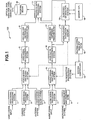
- FIG. 1 is a block diagram of a first illustrative embodiment of the present invention, designated as recording apparatus 100.
- recording apparatus 100 is configured to selectively receive various types of analog input signals, such as a television broadcast signal or a camera system output signal.
- the apparatus converts the selected input signal to a digital signal, and compresses and records the same on a digital storage medium such as an optical or magnetic disk.
- characteristics of the audio signal are analyzed over time so as to categorize its contents in a time-segmented manner.
- individual frames of the audio signal are analyzed to determine which frames or frame sequences correspond to, e.g., music, conversational speech, or muted audio.
- Each segment of the recorded audio program is thereby categorized.
- a user table of contents is then generated corresponding to the categorization of the audio signal.
- the table of contents is recorded onto the digital storage medium, either in a specific region of the recording medium, or distributed as subcodes in the same regions as the recorded audio/video data.
- the table of contents allows a user to play back a selected type of audio and associated video data while skipping other types, or to quickly access desired portions of the recorded audiovisual program by selective skipping of certain audio types, and so forth.
- Video signal processing system 1 is configured to receive an external input video signal, such as a VTR video output, and perform various kinds of processing on the signal such as automatic gain control (AGC).
- a camera signal processing system 2 operates to receive a video signal from a charge coupled device (CCD) camera or the like and convert it into a standard protocol signal such as a National Television System Committee (NTSC) video signal.
- Tuner system 3 receives a television broadcast signal via an antenna system (not shown), and converts a selected channel of the television signal into video and audio signals through video detection, video amplification and audio detection.
- Audio signal processing system 7 is adapted to receive and amplify an external audio signal, e.g., the audio output from the VTR supplying the video signal to system 1.
- a microphone input audio processing system 8 amplifies an audio signal inputted through a microphone and performs AGC processing thereon.
- video signal switching system 4 which switches a selected one of the video signals to its output in accordance with a selection control signal from system controller 14.
- audio signal switching system 9 routes the selected one of the audio signals from systems 3, 7 and 8 to its output based on the control signal from system controller 14.
- the analog video output of switching system 4 is applied to video signal A/D conversion system 5 where it is converted to a digital video signal and then quantized.
- the quantized, digital video signal is then compressed by video compressing and processing system 6 in accordance with a standard compression protocol such as the joint photographic experts group (JPEG) or the moving picture experts group (MPEG) schemes.
- JPEG joint photographic experts group
- MPEG moving picture experts group
- the analog audio output of audio switching system 9 is converted to digital audio signal by audio signal A/D conversion system (A/D converter) 10.
- A/D converter audio signal A/D conversion system
- the digitized audio output from A/D converter 10 is applied to both an audio features extraction system 12 (detecting means) and to an audio signal band compression system 11, the latter of which compresses the audio when necessary in accordance with a standard protocol such as MPEG.
- Audio features extraction system 12 includes processing circuitry to analyze certain characteristics of the digital audio signal applied thereto from system 10, to thereby extract audio features from the signal.
- the quantized audio signal is quadrature - transformed in extraction system 12 based on operating parameters supplied thereto from system controller 14, and then subjected to a specified operation in accordance with an operating command also supplied by system controller 14.
- the audio signal is analyzed in extraction system 12 on a block by block basis, where each block corresponds to a specific time segment (e.g., frame or set of frames) of the audio signal to be recorded.
- the audio signal may be analyzed in 0.02 second blocks to determine which blocks contain muted or low level audio.
- the audio signal is analyzed over larger blocks of time to determine which of the larger blocks contain audio corresponding to, e.g., instrument music, human speech or vocal music. Based on the results of the analysis performed by extraction system 12, subcodes are generated by a subcodes generation system 13 to characterize each such block of the audio signal. Certain subcodes are temporarily stored within memory 16.
- a subcode "A” is generated as indicative of whether or not that block corresponds to muted audio.
- a subcode "B” is generated which is indicative of the type of audio contained in that block, e.g., conversation, instrument music or vocal music.
- Subcodes A are directly transferred to recording data processing system 17, whereas subcodes B are transferred to memory circuit 16 for temporary storage therein.
- all subcodes B are transferred as a block from memory 16 to recording data processing system 17 (via subcodes generation system 13) under the control of system controller 14.
- the analog audio signal is received by recording apparatus 100, it is digitized, compressed and recorded as data, generally in real time, on a predetermined portion of the recording medium 18.
- a user table of contents (U-TOC) is generated to correlate the audio data being stored on recording medium 18 with the subcodes characterizing the respective segments of the audio data.
- the U-TOC is stored on recording medium 18.
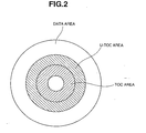
- the digitized audio data may be recorded on the outermost region of the disk, and the U-TOC data may be recorded on a predetermined area of the disk outside the innermost region where a table of contents (TOC) is recorded.
- System controller 14 is configured to control the respective processing systems by supplying control signals thereto based on a user's instruction inputted through recording control signal input system 15, e.g., a keyboard or the like.
- Recording data processing system 17 operates to multiplex bit sequences that are supplied from video compression system 6, audio compression system 11, and subcodes generation system 13, and to transfer the multiplexed data to recording medium 18 and record the data thereon. (It is noted that some or all of the subcodes may optionally be transferred as a block without being multiplexed with the audio and video data, in which case recording system 17 just records the block of subcodes on the recording medium without multiplexing).
- Recording medium 18 may be an optical disk, a hard disk, a memory card, or the like.
- FIG. 3 is a flowchart illustrating process steps executed within system controller 14 to control various aspects of the recording process of recording apparatus 100.
- system controller 14 determines an operating mode based on a user's instruction input to input system 15, e.g, by detecting depression of a particular mode key.
- step S2 it is ascertained whether the operating mode determined in step S1 is a normal recording mode, i.e., a mode in which both video and audio signals are recorded. If so, the routine proceeds to step S3, where system controller 14 sets operation parameters A, B, C, and D in the audio features extraction system 12.
- parameters A-D are set in accordance with the type of audio signal selected by the user, e.g., audio signal from a television signal, VTR output or microphone.
- the values of parameters A-D correspond to the switching state of audio switching system 9, which is controlled by system controller 14.
- FIG. 4 shows a flowchart illustrating a routine within audio features extraction system 12 and subcodes generation system 13.
- one data block contains N bits or bytes of audio data, where N is a predetermined integer.
- one block may contain digitized audio data corresponding to a 0.02 second long segment of the input analog audio signal.
- subcode A is calculated on a block-by-block basis
- subcode B is calculated on an M-block basis, where M is a specified integer.
- audio features extraction system 12 receives operation parameters A, B, C, and D from system controller 14, which parameters have been set in accordance with the type of audio signal selected as discussed previously. If, in step S22, it is determined that M blocks have not yet been processed, the single block process ("1-block process”) of step S27 is executed.
- FIG. 5 is a flow chart illustrating the 1-block process.
- step S31 a fast Fourier transform (FFT) is performed on a single block of the audio signal to determine the spectral components of the portion of the signal corresponding to that block.
- step S32 audio signal power is calculated from Nb frequency components that are specified by operation parameter B supplied from system controller 14.
- the portion of the input audio signal band to be used in calculating signal power is thus determined by parameter B.
- an audio signal from a camera system includes a considerable amount of low frequency components such as zip, while an audio signal of a television broadcast includes a considerable amount of components at harmonic frequencies of the frame frequency.
- noise-induced errors can be reduced by appropriately filtering out undesired frequencies in accordance with the type of audio signal being analyzed.
- step S33 it is ascertained whether or not the signal is mute. That is, if the calculated power value is smaller than parameter C, the signal is determined to be mute within the associated block. Optionally, when the computed power is larger than C, a further determination can be made as to whether the signal power is within one of several predetermined ranges.
- subcode A is generated in step S34 in accordance with the determination of step S33, and supplied to the recording data processing system 17. Subcode A will either be of a first predetermined value for a mute condition, or one of a number of other predetermined values each corresponding to a different range of signal power levels.
- signals of a television broadcast and of a camera system have different signal to noise (S/N) ratios because of differences in microphone performance. Therefore, the possibility of erroneous detection can be reduced by appropriately selecting the value of parameter C in accordance with the selected switching position of audio switching system 9 (and the control thereof by system controller 14).
- the next step in the 1-block process, S35 is to determine the spectral peak P(f), i.e., the peak amplitude at any one of Nd specified frequencies, where Nd is an integer.
- the spectral peak so determined is then stored temporarily in memory circuit 16.
- the Nd frequencies are determined based on the parameter D supplied from system controller 14.
- the spectral components that add noise to the audio signal are a function of the audio signal type. Accordingly, the peak spectral power can be calculated with higher accuracy by eliminating those noise components from the subject frequency components.
- step S27 is executed M times whereby spectral peaks P(f) are computed and stored in memory for M blocks of the audio signal.
- step S23 the software calculates an average continuous length "CL AVG " in which the spectral peaks P(f) are determined to be of similar levels to one another.
- the calculation of CL AVG entails comparing the spectral peaks P(f) of a sequence of blocks to one another and determining segment lengths at which the peaks of sequential blocks remain within a predefined range of one another.
- step S24 it is then determined whether the computed value of CL AVG for that series of M blocks is larger than parameter A supplied from system controller 14.
- the average number of blocks for computing CL AVG is large when the pitch of sound is relatively stable as in the case of music.
- the average number of blocks is small when the audio signal comprises human speech or conversation. For the case of music, it may be determined that certain values for CL AVG correspond to music produced by an instrument while other values correspond to vocal music.
- a subcode B is established for each M-block segment of the audio signal as corresponding to the particular type of audio signal. In this example, it is determined whether the signal is music or not based on whether the value CL AVG is larger than parameter A provided by system controller 14, and subcode B is generated accordingly.
- the subcode B is stored in memory circuit 16 in step S26 and the process is then repeated for the next M blocks, for as long as the operating mode remains the normal recording mode.
- signals of a television broadcast and of camera system e.g., camcorder
- have different rates of occurrence of non-music items such as conversational speech. Therefore, the possibility of erroneous detection can be reduced via appropriate selection of the value of parameter A in accordance with the type of input audio signal selected.
- step S4 the compressed video output signal from video processing system 6 is transferred to recording medium 18 through recording data processing system 17 via control commands from system controller 14.
- System controller 14 also controls the audio processing system 11 in step S5 so that a compressed audio signal is transferred to recording medium 18 via recording processing system 17.
- step S6 system controller 14 controls recording processing system 17 so that the above-discussed subcodes "A" generated by subcodes generation system 13 are supplied to recording processing system 17 and transferred to recording disk 18.
- step S7 if one or more subcode B has been generated, subcodes generation system 13 is instructed to transfer the same to memory circuit 16.
- step S8 it is ascertained whether the previously generated subcodes B have already been recorded onto recording medium 18. If not, system controller 14 controls subcodes generation system 13 (step S9) so as to read out subcodes B stored in memory circuit 16 and transfer them to recording medium 18 via recording data processing system 17.
- subcodes B are recorded as a block onto a predetermined region of recording medium 18, e.g., on the U-TOC region as discussed above.
- step S10 determines whether the current operating mode is a stop mode. If so, a stop process is executed in step S12. Otherwise, it is determined in step S11 whether the operating mode is a removal mode, and if so, a removal mode process is executed in step S13, and the routine returns to step S1.
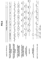
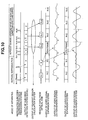
- FIGS. 6 and 7 are timing diagrams showing output timing for signals of the respective audio and video processing systems.
- FIG. 6 shows output timing in a normal recording mode.
- the audio, video and muting data (subcode A) are recorded continually on the recording medium on a frame by frame basis.
- the compressed video data of the (N-1)st frame is recorded first, followed by the compressed audio data of the (N-1)st frame, then the subcode A for frame N-1, which is followed by the video data of the Nth frame, and so forth. It is understood that different data storing sequences may be implemented in the alternative.
- the other timing bars of FIG. 6 depict how the illustrative recording sequence is implemented.
- the compressed video data of any given frame is output from video compression system 6 just prior to the compressed audio data being output from audio compression system 11.
- Sufficient time needs to be allocated to perform the aforedescribed "1-block process" on the current frame, i.e., to perform a quadrature transform (e.g., FFT) on the compressed audio data, to determine subcode A and the spectral peak P(f) as described above for the frame, where one frame corresponds to a single block in this example.
- a quadrature transform e.g., FFT
- P(f) is stored for each frame in memory circuit 16.
- M frames have been processed, e.g., four frames in the example of FIG. 6 (represented by frames N-1 to N+2) then subcode B is generated for that M frame block and written to memory circuit 16.
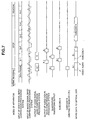
- FIG. 7 is a timing diagram showing illustrative output timing of signals outputted from the respective processing systems as transitions are made from a normal recording mode to a stop mode, and then to a removal mode.
- the transition to the stop mode is effectuated when frame N is captured.
- all of the subcodes B stored in memory circuit 16 are read out by subcodes generation system 13 and recorded onto recording medium 18 via the recording data processing system 17.
- 0 sec's type represents, for instance, the type of audio, e.g., voice, music, etc., that will be reproduced during a period of 0 through 1 seconds from the start of a reproduction
- 1 sec's type represents the audio type reproduced during a period of 1 through 2 seconds from the start
- 8191 sec's type represents the audio type that will be reproduced during a period of 8191 to 8192 seconds from the start.
- the audio types may be defined as follows:
- embodiments of the invention such as recording apparatus 100 just described, are advantageously capable of receiving an analog audio or audiovisual program such as a broadcast, recording the same digitally while simultaneously analyzing the audio content as it is being recorded, and creating a user table of contents (U-TOC) characterizing the different portions of the recorded audio program.
- U-TOC user table of contents
- the user can advantageously employ the U-TOC (with appropriate electronics such as those to be described) to find certain portions of the recorded material, skip portions with undesired audio types, and so forth. Consequently, the user is provided with a highly efficient tool during the playback process.
- FIG. 8 is a block diagram showing an illustrative configuration of an information reproduction apparatus 200 according to an embodiment of the invention.
- Recording medium 18 is similar to that shown in FIG. 1, e.g., an optical disk, memory card, or magnetic hard disk. Audio and video data and corresponding subcodes A and B characterizing the different time segments of the audio, are recorded on the recording medium 18. If the recording medium is an optical disk, data can be recorded according to the following format:
- 5 byte audio IDs may be stored with the lowest one byte representing an audio level as follows: XXXX0 level-0 XXXX1 level-1 XXXX2 level-2 XXXXA level-N; and the second lowest byte represents audio content in this example: XXX0X: mute XXX1X: music (pop) XXX2X: music (classic) . . . XXXAX: voice
- X represents an arbitrary value of 0 to 255.
- a given sector may contain only subcodes.
- subcodes may be arranged as a batch in a given region such as a U-TOC region.
- an apparatus can be implemented by using the same configuration and processes as in the above example.
- reproduction apparatus 200 will be described with the assumption that recording medium 18 is an optical disk.
- a driving circuit 21 (in this case, an optical disk driving circuit) is configured to servo-control optical disk 18 to enable specified sectors of the disk to be accessed in response to an external control signal.
- An optical pickup (not shown), which may be part of reproduction processing system 22, reads out signals from disk 18, and amplifies and demodulates the same.
- Reproduction data processing system 22 operates to separate video data, audio data, and subcodes from data that is read out from recording medium 18, and to provide the subcodes to subcodes detection system A 28.
- Video signal band expansion processing system 23 operates to expand the compressed video data supplied from processing system 22, and to convert the expanded data into a baseband signal of, e.g., 13.5 MHz, YUV, or the like.
- Video signal D/A conversion system 24 converts received digital video data into an analog video signal.
- Audio signal band expansion processing system 25 expands audio data that has been compressed according to the MPEG scheme or the like.
- Audio signal D/A conversion system 26 converts received digital audio data into an analog audio signal.
- Readout region calculation system 27 calculates a sector number of recording medium 18 based on a control signal sent from system controller 29 or subcodes detection system A 28 (determining means). Detection system 28 is configured to determine whether subcodes (and associated frames) that are read out from recording medium 18 correspond to the audio type of a current reproduction mode. Detection system 28 supplies a control signal to calculation system 27 in accordance with this determination. Detection system 28 also provides video expansion system 23 and audio expansion system 25 with a control signal as an instruction to refrain from outputting data from a frame when that frame is to be skipped. System controller 29 is operative to control the entire recording apparatus 200 based on data input by a user through input system 30, e.g., a user panel of depressible selection keys.
- the various systems of apparatus 200 e.g., systems 22, 23, 25 and 27-29, may be embodied either as separate firmware or as part of a common processor with suitable software running thereon to realize the functions of the respective systems.
- step S41 system controller 29 determines an operating mode based on user depression of one or more keys of input system 30.
- the operating mode may be selected from a normal reproduction mode in which audio and video data are output continuously, or, one or more "skipping" reproduction modes in which a specified audio type is skipped during reproduction.
- step S42 readout region calculation system 27 calculates a sector number of the next subcode to be read out.
- step S43 the calculated sector number is supplied to driving circuit 21, and the subcode corresponding to the calculated sector number is read out from recording medium 18 under the control of driving circuit 21.
- the calculated sector number and associated subcode are supplied to detection system 28 via processing system 22.
- step S44 it is determined whether the current operating mode is the normal reproduction mode, and if so, the process flows to step S45, where calculation system 27 calculates the sector number of the next frame and supplies it to driving circuit 21.
- step S46 compressed audio and video data corresponding to the next frame are read out from recording medium 18 under the control of driving circuit 21.
- This compressed video and audio data are transferred to video expansion system 23 and audio expansion system 25, respectively, via processing system 22 (steps S47, S48).
- the compressed video data that has been transferred to video expansion system 23 is expanded therein, then converted into an analog video signal by video D/A converter 24, and finally output.
- the compressed audio data that has been transferred to audio expansion system 25 is expanded therein, converted into an analog audio signal by audio D/A converter 26, and then output.
- the routine then returns to step S41 to repeat the foregoing process.
- step S44 system controller 29 determines that the current operating mode is different than the normal reproduction mode, e.g., that the mode is reproduction mode A (step S49), or reproduction mode B (step S51), then apparatus 200 is controlled to output audio and video data in accordance with the reproduction mode selected.
- the reproduction mode selected by the user may be designed to cause apparatus 200 to skip one particular type of audio during playback. In this case, frames are skipped if their associated subcode corresponds to the audio type to be avoided.
- Detection system 28 would then instruct expansion systems 23 and 25 not to output data corresponding to that frame. Concomitantly, calculation system 27 is instructed to immediately skip the sector of that frame and move on to subsequent frame sectors until a frame is found having a different subcode than the one to be avoided.
- reproduction mode may be included to allow for playback of only one type of audio while skipping all other types.
- detection system 27 provides "skip" commands as described above to calculation system 27 and expansion systems 23, 25 when the current frame subcode does not correspond to the audio type selected to be played back.
- another reproduction mode may be included which implements a specific viewing and/or listening speed inputted by the user, in which case both video and audio signals can be skipped in synchronism with one another by calculating a ratio between frames to be reproduced and frames to be skipped.
- reproduction mode A corresponds to a mode in which frames with muted or low level audio are to be skipped. If it is determined in step S50 that a frame is to be skipped because its subcode corresponds to a low audio level, then the routine returns to steps S42 and S43 where the sector for the subsequent frame is calculated, the subcode is read out and the process is repeated. If the frame is not to be skipped, the routine returns from inquiry S50 to step S45 to commence the playback process for the audio/video data of that frame.
- a variety of reproduction operations can be performed by determining the content of a subject subcode in response to a command from system controller 29, and then calculating readout sectors based on the determination.
- this technique since a video signal and an audio signal are always skipped or reproduced in synchronism with each other, no timing deviation occurs between them.
- FIG. 10 is a timing diagram showing output timing of the signals output from respective processing systems in the normal reproduction mode and in an illustrative reproduction mode A.
- the normal reproduction mode every frame is read out irrespective of the subcode value.
- reproduction mode A frames may be skipped depending on the read-out subcode value.
- frames having audio levels of level-0 and level-1 are skipped, i.e., frames in which the lowest byte of the illustrative 5-byte audio ID of the subcode is "0" or "1" are skipped.
- frames N+1, N+2, and N+4 are skipped and frames N+3, N+5, and N+6 are read out from recording medium 18 under the control of readout region calculating system 27.
- Video and audio signals of the non-skipped frames i.e., frames N+3, N+5, and N+6 in this example, are reproduced in synchronism with each other.
- FIG. 11 is a block diagram showing another illustrative configuration of an information reproduction apparatus 300, which is another embodiment of the invention.
- Reproduction apparatus 300 differs from the above-described apparatus 200 of FIG. 8 in that a subcode detection system B 41 in FIG. 11 is substituted for the system A 28 in FIG. 8, and a memory circuit 42 (storing means) is included in FIG. 11. Since the other components of apparatus 300 and the operation thereof are the same as the corresponding components of apparatus 200, descriptions thereof will be omitted.
- Subcodes detection system B 41 is configured to read out subcodes that are recorded on the recording medium 18 and then store those subcodes in memory circuit 42. Preferably, these subcodes are read out from recording medium 18 as a block during an allocated time interval.
- System 41 also operates to receive a "reproduction mode" control signal from system controller 29 indicative of which audio data is to be reproduced (or skipped).
- system 41 reads out subcodes stored in memory 42 and determines whether to reproduce the audio/video data of a given frame based on a comparison of that frame's associated subcode with the reproduction mode selected. System 41 then controls readout region calculation system 27 in accordance with the comparison.
- Memory circuit 42 is a semiconductor memory device or the like, such as a random access memory, and, by way of example, may be stored with the following subcodes: Address Data 0000 0th-frame subcode 0001 1st-frame subcode . . . . . XXXX Nth-frame subcode
- step S61 subcodes detection system B 41 reads out all subcodes stored on recording medium 18, and transfers the subcodes to memory 42 for storage.
- the subcode readout process is effectuated by system 41 providing control commands to calculation system 27, which in turn provides control signals to driver circuit 21 for accessing the proper region of the disk.
- step S62 an operating mode is determined based on data input via a user key depression through input system 30.
- detection system 41 reads out a subcode of a specific frame from memory 42, i.e., the next frame in a reproduction sequence to be selected as a candidate for possible playback of audio/video data. If in step S64, the current operating mode is determined to be the normal reproduction mode, the subcodes are irrelevant since no frames are skipped. In this case, calculation system 27 calculates a sector number of the next frame and driving circuit 21 is controlled accordingly (step S65). Audio/video data of the next frame is then read out from recording medium 18 and supplied to reproduction data processing system 22 (step S66).
- Processing system 22 then separates the audio data from the video data, transfers the audio data to expansion system 25 and the video data to expansion system 23 (steps S67, S68).
- the signals are expanded in the respective expansion systems 23, 25, converted to analog signals by respective D/A converters 24, 26 and then output. The process is then repeated for the subsequent frames.
- step S64 system controller 29 determines that the current operating mode is different than the normal reproduction mode, e.g., reproduction mode A (step S69) or reproduction mode B (step S71), then apparatus 300 is controlled to output audio and video data in accordance with the reproduction mode selected.
- the reproduction mode selected e.g., reproduction mode A (step S69) or reproduction mode B (step S71).
- some of the alternative reproduction modes may be designed to cause apparatus 300 to skip a particular type of audio during playback. In this case, frames are skipped if their associated subcode corresponds to the audio type to be avoided.
- Another reproduction mode may be included to allow for playback of only one type of audio while skipping all other types.
- Yet another reproduction mode may be included which implements a specific viewing and/or listening speed inputted by the user, as mentioned previously.
- step S70 if it is determined in step S70 that a frame is to be skipped based on a positive correlation with its subcode and reproduction mode A (e.g., mute condition skipping or vocal song skipping, etc.) then the routine returns to step S63 where the subcode from the subsequent frame is read out and the process is repeated. If the frame is not to be skipped, the routine returns to step S65 to commence the playback process for the audio/video of that frame as described above.
- subcode and reproduction mode A e.g., mute condition skipping or vocal song skipping, etc.
- FIG. 13 is a timing diagram illustrating the timing of signals that are output from the respective processing systems in making a transition from a normal reproduction mode to reproduction mode A.
- subcodes are initially read out as a block in a subcodes readout mode.
- a subcode corresponding to a current frame to be played back is read out from memory circuit 42, and video and audio data of that frame are read out from recording medium 18.
- the video data is supplied to and expanded by video expansion system 23, then converted into an analog video signal by video D/A converter system 24, and finally output.
- the audio data is supplied to and expanded by audio expansion system 25, then converted into an analog audio signal by D/A converter 26 for outputting.
- reproduction mode A frames having subcodes indicating audio levels lower than a specified level are skipped during playback.
- frames whose audio levels are lower than level-2 are skipped while frames with audio levels higher than level-1 are reproduced. Since video data and audio data are skipped in synchronism with each other, reproduced video and audio signals are also synchronized with one another.
- the above-described embodiments of recording and reproduction apparatuses can be modified in a variety of ways without departing from the spirit and scope of the invention.
- the above embodiments specifically illustrate discrimination between two classes of audio -- low level audio and music -- the embodiments can be modified to allow for discrimination among three or more types of audio.
- the discrimination may alternatively be performed by detecting a plurality of spectral peaks relative to the highest level for each block, and calculating their continuity, e.g., over M blocks.
- the discrimination between music and non-music and/or between muted and non-muted audio may be made by using one of various, currently proposed speech recognition devices, with the discrimination result being recorded as a subcode.
- playback and skipping are controlled on a frame-by-frame basis based on subcode contents.
- playback of a short audio/video segment for instance, a one or two-frame segment, may be recognized in many cases merely as noise.
- This problem can be solved by setting in advance the minimum continuous sequence of frames to be played back. Then, frames would be played back, rather than skipped, so long as the minimum sequence has not yet been reached, even if their subcodes indicate a skip.
- subcode A (which is indicative of the audio level feature) may be generated for every two frames rather than for every frame as described. Further, another reproduction mode based on subcode A may be included which allows a user to automatically skip louder portions (higher levels) of the audio signal, e.g., loud music, while playing back audio at lower levels.
Abstract
Description
- The present invention relates to information recording and reproduction, and more particularly, to recording apparatus, recording methods, reproduction apparatus and reproduction methods. The method and apparatus are applicable to audio or audio and video signals.
- Presently, analog-type video tape recorders (VTRs) are commonly used to record and reproduce analog video and audio signals of a television broadcast. It is contemplated that digital data corresponding to such analog video and audio signals will be commonly recorded on a digital storage medium such as an optical disk or a magnetic hard disk.
- With conventional VTRs, reproduction is facilitated by introducing various identifying signals during the recording process. For example, one type of identifying signal is used to identify whether a television broadcast is a bilingual broadcast or a stereo broadcast. As a result, a television receiver can discriminate between these two types of broadcasts and control the audio signal output method accordingly.
- Contemporary optical disks and hard disks have superior accessibility, i.e., random access capability, as compared to analog magnetic tapes. As such, various fast viewing and listening methods are now being considered for these disks, such as speech speed conversion and selective skipping of song contents. In contrast, conventional VTRs lack such capability. Some prior art VTRs include an automatic audio selection function or the like, while others have a speech speed conversion feature. A drawback of the speech speed conversion feature, however, is that video and audio are processed independently. This is problematic in that the output audio and video may become unsynchronized, resulting in unnatural audiovisual output, e.g., lips moving before or after the audio is produced.
- Conventional laser disc players ("LDPs") are capable of header search for karaoke use (i.e., for in use in a sing-along machine). However, in the case of ordinary broadcasts, users in many instances desire to view conversational-type programs between musical performance programs. In these cases, the conventional LDP, which is capable only of header search, is inadequate.
- EP-A-0 510 876 relates to an audio signal recording apparatus in which an audio signal is compared with a plurality of different threshold levels and, on the basis of this comparison, music-present or music-absence information is recorded on the recording medium together with the audio signal.
US 5,590,100 relates to an information recording/reproducing technique for recording plural channel information in a manner that it may be simultaneously reproduced.
Information indicating recording start and recording end positions are identified when recording is performed with respect to any of the channels. Reproduction information designating this section of the channel as a section of the channel to be reproduced is generated and reproduction information designating other sections as sections to be silenced is also generated. This arrangement permits automatic generation of reproduction information indicating positions to be reproduced and silenced in accordance with recording start and end operations. - US 5,377,167 relates to a recording reproducing device for recording additional information relating to sound information recorded in a sound information recording region. The provision of the additional information enables the reproduction of unnecessary sound information to be avoided and a pause to be provided between melodies. The additional information provides recording silencing information or fading information which controls the performance of silencing or fade-in/fade-out processes during reproduction from the recording medium.
- Aspects of the invention are specified in
claims - An embodiment of the present invention seeks to provide a recording apparatus capable of recording an audio or audiovisual signal on a digital storage medium, while concomitantly analysing its characteristics over time for particular audio types and storing information indicative of such characteristics on the storage medium.
- A further embodiment of the invention seeks to provide a reproduction apparatus that allows for selective reproduction of the audio or audiovisual signal so recorded based on user selection of a particular audio type.
- Another embodiment of the invention seeks to provide recording and reproduction apparatuses with enhanced features.
- In an illustrative embodiment of the invention, there is provided an information recording apparatus for recording at least an audio signal onto a recording medium, which includes detection circuitry for detecting a feature of the audio signal, and recording circuitry for recording together with the audio signal additional information that corresponds to the detected feature. Preferably, features of the audio signal are detected in a time-segmented manner, such that segments or frames of the audio signal are each characterized. For example, features that may be detected by the detection circuitry may include: whether a given segment comprises muted audio; whether it comprises music; or whether it comprises conversational speech.
- With the feature information stored on the recording medium, versatility during reproduction is advantageously possible, thereby providing the user with a highly versatile tool during playback. For instance, the user is able to skip portions of the recorded material having an undesired audio type or types, or to quickly locate a desired portion of the recorded material by selective skipping based on audio types.
- In another illustrative embodiment, there is provided an information reproduction apparatus for reproducing at least an audio signal corresponding to audio data recorded on a recording medium on which additional information relating to at least the audio signal is also recorded. The apparatus includes reading means for reading out a portion of the additional information prior to any reproduction of a corresponding portion of the audio signal; determining means for determining whether to reproduce the corresponding portion of the audio signal in accordance with the read-out portion of the additional information and a current operating mode; and control means for controlling reproduction of the corresponding portion of the audio signal in accordance with a determination by the determining means.
- The following detailed description, given by way of example and not intended to limit the present invention solely thereto, will best be appreciated in conjunction with the accompanying drawings, in which like reference numerals denote like elements and parts, wherein:
- FIG. 1 is a block diagram of an illustrative configuration of an information recording apparatus according to an embodiment of the present invention;
- FIG. 2 illustrates an illustrative arrangement of storage regions on a disk;
- FIG. 3 is a flowchart showing the operation of the information recording apparatus of FIG. 1;
- FIGS. 4 and 5 are flowcharts showing a process of generating a subcode indicative of an audio feature;
- FIGS. 6 and 7 are timing diagrams showing output timing of signals flowing within the respective processing systems of FIG. 1;
- FIG. 8 is a block diagram showing an illustrative configuration of an information reproduction apparatus according to an embodiment of the invention;
- FIG. 9 is a flowchart showing the operation of the information reproduction apparatus of FIG. 8;
- FIG. 10 is a timing diagram showing output timing of signals flowing within the respective processing systems of FIG. 8;
- FIG. 11 is a block diagram showing an illustrative configuration of an information reproduction apparatus according to another embodiment of the invention;
- FIG. 12 is a flowchart illustrating the operation of the information reproduction apparatus of FIG. 11; and
- FIG. 13 is a timing diagram showing output timing of signals flowing within the respective processing systems of FIG. 11.
-
- FIG. 1 is a block diagram of a first illustrative embodiment of the present invention, designated as
recording apparatus 100. As will be described in detail below, recordingapparatus 100 is configured to selectively receive various types of analog input signals, such as a television broadcast signal or a camera system output signal. The apparatus converts the selected input signal to a digital signal, and compresses and records the same on a digital storage medium such as an optical or magnetic disk. As the audio and video signals are received and recorded, characteristics of the audio signal are analyzed over time so as to categorize its contents in a time-segmented manner. In particular, individual frames of the audio signal are analyzed to determine which frames or frame sequences correspond to, e.g., music, conversational speech, or muted audio. Each segment of the recorded audio program is thereby categorized. A user table of contents is then generated corresponding to the categorization of the audio signal. The table of contents is recorded onto the digital storage medium, either in a specific region of the recording medium, or distributed as subcodes in the same regions as the recorded audio/video data. The table of contents allows a user to play back a selected type of audio and associated video data while skipping other types, or to quickly access desired portions of the recorded audiovisual program by selective skipping of certain audio types, and so forth. -
Recording apparatus 100 will now be described in detail. Videosignal processing system 1 is configured to receive an external input video signal, such as a VTR video output, and perform various kinds of processing on the signal such as automatic gain control (AGC). A camerasignal processing system 2 operates to receive a video signal from a charge coupled device (CCD) camera or the like and convert it into a standard protocol signal such as a National Television System Committee (NTSC) video signal.Tuner system 3 receives a television broadcast signal via an antenna system (not shown), and converts a selected channel of the television signal into video and audio signals through video detection, video amplification and audio detection. - Audio
signal processing system 7 is adapted to receive and amplify an external audio signal, e.g., the audio output from the VTR supplying the video signal tosystem 1. A microphone inputaudio processing system 8 amplifies an audio signal inputted through a microphone and performs AGC processing thereon. - The video output signals from each of
systems signal switching system 4, which switches a selected one of the video signals to its output in accordance with a selection control signal fromsystem controller 14. Likewise, audiosignal switching system 9 routes the selected one of the audio signals fromsystems system controller 14. - In the video path, the analog video output of
switching system 4 is applied to video signal A/D conversion system 5 where it is converted to a digital video signal and then quantized. The quantized, digital video signal is then compressed by video compressing andprocessing system 6 in accordance with a standard compression protocol such as the joint photographic experts group (JPEG) or the moving picture experts group (MPEG) schemes. The compressed video signal is applied to recordingdata processing system 17 and recorded inrecording medium 18 as will be discussed more fully below. - In the audio path of
recording apparatus 100, the analog audio output ofaudio switching system 9 is converted to digital audio signal by audio signal A/D conversion system (A/D converter) 10. The digitized audio output from A/D converter 10 is applied to both an audio features extraction system 12 (detecting means) and to an audio signalband compression system 11, the latter of which compresses the audio when necessary in accordance with a standard protocol such as MPEG. - Audio features
extraction system 12 includes processing circuitry to analyze certain characteristics of the digital audio signal applied thereto fromsystem 10, to thereby extract audio features from the signal. The quantized audio signal is quadrature - transformed inextraction system 12 based on operating parameters supplied thereto fromsystem controller 14, and then subjected to a specified operation in accordance with an operating command also supplied bysystem controller 14. The audio signal is analyzed inextraction system 12 on a block by block basis, where each block corresponds to a specific time segment (e.g., frame or set of frames) of the audio signal to be recorded. By way of example, to determine which portions of the audio signal correspond to a mute condition, the audio signal may be analyzed in 0.02 second blocks to determine which blocks contain muted or low level audio. The audio signal is analyzed over larger blocks of time to determine which of the larger blocks contain audio corresponding to, e.g., instrument music, human speech or vocal music. Based on the results of the analysis performed byextraction system 12, subcodes are generated by asubcodes generation system 13 to characterize each such block of the audio signal. Certain subcodes are temporarily stored withinmemory 16. - In particular, for each audio block of duration "D1" (e.g., 0.02 seconds duration), a subcode "A" is generated as indicative of whether or not that block corresponds to muted audio. For each block of a longer duration "D2", a subcode "B" is generated which is indicative of the type of audio contained in that block, e.g., conversation, instrument music or vocal music. Subcodes A are directly transferred to recording
data processing system 17, whereas subcodes B are transferred tomemory circuit 16 for temporary storage therein. Typically, when recording of audio/video data is complete, all subcodes B are transferred as a block frommemory 16 to recording data processing system 17 (via subcodes generation system 13) under the control ofsystem controller 14. - In any event, as the analog audio signal is received by
recording apparatus 100, it is digitized, compressed and recorded as data, generally in real time, on a predetermined portion of therecording medium 18. As the subcodes A and B are generated, a user table of contents (U-TOC) is generated to correlate the audio data being stored on recordingmedium 18 with the subcodes characterizing the respective segments of the audio data. The U-TOC is stored on recordingmedium 18. As shown in FIG. 2, the digitized audio data may be recorded on the outermost region of the disk, and the U-TOC data may be recorded on a predetermined area of the disk outside the innermost region where a table of contents (TOC) is recorded. -
System controller 14 is configured to control the respective processing systems by supplying control signals thereto based on a user's instruction inputted through recording controlsignal input system 15, e.g., a keyboard or the like. - Recording data processing system 17 (recording means) operates to multiplex bit sequences that are supplied from
video compression system 6,audio compression system 11, andsubcodes generation system 13, and to transfer the multiplexed data to recordingmedium 18 and record the data thereon. (It is noted that some or all of the subcodes may optionally be transferred as a block without being multiplexed with the audio and video data, in whichcase recording system 17 just records the block of subcodes on the recording medium without multiplexing). Recordingmedium 18 may be an optical disk, a hard disk, a memory card, or the like. - FIG. 3 is a flowchart illustrating process steps executed within
system controller 14 to control various aspects of the recording process ofrecording apparatus 100. At the outset (step S1)system controller 14 determines an operating mode based on a user's instruction input to inputsystem 15, e.g, by detecting depression of a particular mode key. In step S2, it is ascertained whether the operating mode determined in step S1 is a normal recording mode, i.e., a mode in which both video and audio signals are recorded. If so, the routine proceeds to step S3, wheresystem controller 14 sets operation parameters A, B, C, and D in the audio featuresextraction system 12. For reasons that will become apparent below, the values of parameters A-D are set in accordance with the type of audio signal selected by the user, e.g., audio signal from a television signal, VTR output or microphone. Thus, the values of parameters A-D correspond to the switching state ofaudio switching system 9, which is controlled bysystem controller 14. - Before proceeding further with FIG. 3, reference is made to FIG. 4 which shows a flowchart illustrating a routine within audio features
extraction system 12 andsubcodes generation system 13. For the presently described embodiment, it is assumed that one data block contains N bits or bytes of audio data, where N is a predetermined integer. By way of example, one block may contain digitized audio data corresponding to a 0.02 second long segment of the input analog audio signal. It is further assumed that subcode A is calculated on a block-by-block basis, and that subcode B is calculated on an M-block basis, where M is a specified integer. In step S21, audio featuresextraction system 12 receives operation parameters A, B, C, and D fromsystem controller 14, which parameters have been set in accordance with the type of audio signal selected as discussed previously. If, in step S22, it is determined that M blocks have not yet been processed, the single block process ("1-block process") of step S27 is executed. - FIG. 5 is a flow chart illustrating the 1-block process. In step S31, a fast Fourier transform (FFT) is performed on a single block of the audio signal to determine the spectral components of the portion of the signal corresponding to that block. Next, in step S32, audio signal power is calculated from Nb frequency components that are specified by operation parameter B supplied from
system controller 14. The portion of the input audio signal band to be used in calculating signal power is thus determined by parameter B. For example, an audio signal from a camera system includes a considerable amount of low frequency components such as zip, while an audio signal of a television broadcast includes a considerable amount of components at harmonic frequencies of the frame frequency. Hence, for the signal power calculation, noise-induced errors can be reduced by appropriately filtering out undesired frequencies in accordance with the type of audio signal being analyzed. - In the next step, S33, it is ascertained whether or not the signal is mute. That is, if the calculated power value is smaller than parameter C, the signal is determined to be mute within the associated block. Optionally, when the computed power is larger than C, a further determination can be made as to whether the signal power is within one of several predetermined ranges. In any event, subcode A is generated in step S34 in accordance with the determination of step S33, and supplied to the recording
data processing system 17. Subcode A will either be of a first predetermined value for a mute condition, or one of a number of other predetermined values each corresponding to a different range of signal power levels. In general, signals of a television broadcast and of a camera system (e.g., camcorders) have different signal to noise (S/N) ratios because of differences in microphone performance. Therefore, the possibility of erroneous detection can be reduced by appropriately selecting the value of parameter C in accordance with the selected switching position of audio switching system 9 (and the control thereof by system controller 14). - The next step in the 1-block process, S35, is to determine the spectral peak P(f), i.e., the peak amplitude at any one of Nd specified frequencies, where Nd is an integer. The spectral peak so determined is then stored temporarily in
memory circuit 16. The Nd frequencies are determined based on the parameter D supplied fromsystem controller 14. As discussed above, the spectral components that add noise to the audio signal are a function of the audio signal type. Accordingly, the peak spectral power can be calculated with higher accuracy by eliminating those noise components from the subject frequency components. - Once the spectral peak P(f) for the single block is computed and stored temporarily, the software flow returns to steps S21 and S22 of FIG. 4. The process continues until step S27 is executed M times whereby spectral peaks P(f) are computed and stored in memory for M blocks of the audio signal.
- Once it is determined in step S22 that M blocks of audio data have been processed, then, in step S23, the software calculates an average continuous length "CLAVG" in which the spectral peaks P(f) are determined to be of similar levels to one another. The calculation of CLAVG entails comparing the spectral peaks P(f) of a sequence of blocks to one another and determining segment lengths at which the peaks of sequential blocks remain within a predefined range of one another. In step S24, it is then determined whether the computed value of CLAVG for that series of M blocks is larger than parameter A supplied from
system controller 14. In general, the average number of blocks for computing CLAVG is large when the pitch of sound is relatively stable as in the case of music. Conversely, the average number of blocks is small when the audio signal comprises human speech or conversation. For the case of music, it may be determined that certain values for CLAVG correspond to music produced by an instrument while other values correspond to vocal music. - In any event, in step S25, a subcode B is established for each M-block segment of the audio signal as corresponding to the particular type of audio signal. In this example, it is determined whether the signal is music or not based on whether the value CLAVG is larger than parameter A provided by
system controller 14, and subcode B is generated accordingly. The subcode B is stored inmemory circuit 16 in step S26 and the process is then repeated for the next M blocks, for as long as the operating mode remains the normal recording mode. In - general, signals of a television broadcast and of camera system (e.g., camcorder) have different rates of occurrence of non-music items such as conversational speech. Therefore, the possibility of erroneous detection can be reduced via appropriate selection of the value of parameter A in accordance with the type of input audio signal selected. - Returning to FIG. 3, while the audio signal is being processed in accordance with the aforedescribed control in step S3, the video is continually processed and digitally recorded as well. That is, in step S4, the compressed video output signal from
video processing system 6 is transferred torecording medium 18 through recordingdata processing system 17 via control commands fromsystem controller 14.System controller 14 also controls theaudio processing system 11 in step S5 so that a compressed audio signal is transferred torecording medium 18 viarecording processing system 17. In step S6,system controller 14 controls recordingprocessing system 17 so that the above-discussed subcodes "A" generated bysubcodes generation system 13 are supplied torecording processing system 17 and transferred torecording disk 18. Then, in step S7, if one or more subcode B has been generated,subcodes generation system 13 is instructed to transfer the same tomemory circuit 16. - Thereafter, the process returns to steps S1 and S2. If the operating mode is still the normal operating mode, the aforedescribed process is repeated. If, on the other hand, the operating mode has changed such as by user depression of a "stop recording" key or the like, the routine proceeds to step S8, where it is ascertained whether the previously generated subcodes B have already been recorded onto
recording medium 18. If not,system controller 14 controls subcodes generation system 13 (step S9) so as to read out subcodes B stored inmemory circuit 16 and transfer them to recordingmedium 18 via recordingdata processing system 17. - In the above manner, when a transition is made from the normal recording mode to some other mode, subcodes B are recorded as a block onto a predetermined region of
recording medium 18, e.g., on the U-TOC region as discussed above. - If in step S8 the subcodes B have already been recorded on
recording medium 18, the next step (step S10) is to determine whether the current operating mode is a stop mode. If so, a stop process is executed in step S12. Otherwise, it is determined in step S11 whether the operating mode is a removal mode, and if so, a removal mode process is executed in step S13, and the routine returns to step S1. - FIGS. 6 and 7 are timing diagrams showing output timing for signals of the respective audio and video processing systems. FIG. 6 shows output timing in a normal recording mode. As is apparent from the bottom-most timing bar of the figure, during the normal operating mode, the audio, video and muting data (subcode A) are recorded continually on the recording medium on a frame by frame basis. In the presently described embodiment, the compressed video data of the (N-1)st frame is recorded first, followed by the compressed audio data of the (N-1)st frame, then the subcode A for frame N-1, which is followed by the video data of the Nth frame, and so forth. It is understood that different data storing sequences may be implemented in the alternative. The other timing bars of FIG. 6 depict how the illustrative recording sequence is implemented. The compressed video data of any given frame, e.g., the Nth frame, is output from
video compression system 6 just prior to the compressed audio data being output fromaudio compression system 11. Sufficient time needs to be allocated to perform the aforedescribed "1-block process" on the current frame, i.e., to perform a quadrature transform (e.g., FFT) on the compressed audio data, to determine subcode A and the spectral peak P(f) as described above for the frame, where one frame corresponds to a single block in this example. Thus, the quadrature transform for the Nth frame is performed prior to outputting the compressed audio data of the Nth frame, while the generation of subcode A for the Nth frame is completed immediately after the compressed audio data is outputted. Also, P(f) is stored for each frame inmemory circuit 16. After M frames have been processed, e.g., four frames in the example of FIG. 6 (represented by frames N-1 to N+2) then subcode B is generated for that M frame block and written tomemory circuit 16. - FIG. 7 is a timing diagram showing illustrative output timing of signals outputted from the respective processing systems as transitions are made from a normal recording mode to a stop mode, and then to a removal mode. In this example, it is assumed that the transition to the stop mode is effectuated when frame N is captured. After the compressed video and audio signals and subcodes A corresponding to frames N-1 and N are recorded onto
recording medium 18, all of the subcodes B stored inmemory circuit 16 are read out bysubcodes generation system 13 and recorded ontorecording medium 18 via the recordingdata processing system 17. - The particular sector configuration and format used for the subcodes A and B are not critical to the present invention.
The following are presented by way of example: -
Sync pattern 8 bytes Subcode 9 bytes Parity 8 bytes User data 2,048 bytes ECC (error correcting code) 256 bytes Total 2,329 bytes -
Sector number 4 bytes Audio level 5 bytes Total 9 bytes -
000: mute 001: level-0 010: level-1 011: level-2 . . . . . . 1XX level-N -
Sync pattern 8 bytes Parity 8 bytes User data 2,048 bytes Subcode B 8,192 bytes ECC (error correcting code) 256 bytes Total 10,512 bytes -
0 sec's type: 1 byte 1 sec's type: 1 byte . . . . . . 8,191 sec's type: 1 byte Total 8,192 bytes - In the above example, "0 sec's type" represents, for instance, the type of audio, e.g., voice, music, etc., that will be reproduced during a period of 0 through 1 seconds from the start of a reproduction, "1 sec's type" represents the audio type reproduced during a period of 1 through 2 seconds from the start, and so forth. "8191 sec's type" represents the audio type that will be reproduced during a period of 8191 to 8192 seconds from the start. For example, the audio types may be defined as follows:
-
000 mute 001 music-0 (e.g., instrument music) 010 music-1 (e.g., vocal music) 011 human voice (e.g., conversational speech) 1XX other types - Accordingly, it should be readily apparent that embodiments of the invention such as
recording apparatus 100 just described, are advantageously capable of receiving an analog audio or audiovisual program such as a broadcast, recording the same digitally while simultaneously analyzing the audio content as it is being recorded, and creating a user table of contents (U-TOC) characterizing the different portions of the recorded audio program. During playback, the user can advantageously employ the U-TOC (with appropriate electronics such as those to be described) to find certain portions of the recorded material, skip portions with undesired audio types, and so forth. Consequently, the user is provided with a highly efficient tool during the playback process. - Illustrative apparatuses for reproducing audio and video that have been stored along with additional audio feature information on a digital storage medium in the above-discussed manner, will now be described.
- FIG. 8 is a block diagram showing an illustrative configuration of an
information reproduction apparatus 200 according to an embodiment of the invention. Recordingmedium 18 is similar to that shown in FIG. 1, e.g., an optical disk, memory card, or magnetic hard disk. Audio and video data and corresponding subcodes A and B characterizing the different time segments of the audio, are recorded on therecording medium 18. If the recording medium is an optical disk, data can be recorded according to the following format: -
Sync pattern 8 bytes Subcode 9 bytes Parity 8 bytes User data 2,048 bytes ECC (error correcting code) 256 bytes Total 2,329 bytes -
Sector number 4 bytes Audio ID 5 bytes Total 9 bytes - By way of example, 5 byte audio IDs may be stored with the lowest one byte representing an audio level as follows:
XXXX0 level-0 XXXX1 level-1 XXXX2 level-2 XXXXA level-N; XXX0X: mute XXX1X: music (pop) XXX2X: music (classic) . . . XXXAX: voice - In the above example, X represents an arbitrary value of 0 to 255.
- Although the above example is directed to the case in which a subcode is located in the same sector as video and audio data, as an alternative, a given sector may contain only subcodes. Further, as in the case of a mini-disc (MD), subcodes may be arranged as a batch in a given region such as a U-TOC region. For this case, an apparatus can be implemented by using the same configuration and processes as in the above example.
- In the following discussion,
reproduction apparatus 200 will be described with the assumption that recordingmedium 18 is an optical disk. A driving circuit 21 (in this case, an optical disk driving circuit) is configured to servo-controloptical disk 18 to enable specified sectors of the disk to be accessed in response to an external control signal. An optical pickup (not shown), which may be part ofreproduction processing system 22, reads out signals fromdisk 18, and amplifies and demodulates the same. Reproductiondata processing system 22 operates to separate video data, audio data, and subcodes from data that is read out from recordingmedium 18, and to provide the subcodes to subcodesdetection system A 28. - Video signal band
expansion processing system 23 operates to expand the compressed video data supplied from processingsystem 22, and to convert the expanded data into a baseband signal of, e.g., 13.5 MHz, YUV, or the like. Video signal D/A conversion system 24 converts received digital video data into an analog video signal. Audio signal bandexpansion processing system 25 expands audio data that has been compressed according to the MPEG scheme or the like. Audio signal D/A conversion system 26 converts received digital audio data into an analog audio signal. - Readout region calculation system 27 (control means) calculates a sector number of
recording medium 18 based on a control signal sent fromsystem controller 29 or subcodes detection system A 28 (determining means).Detection system 28 is configured to determine whether subcodes (and associated frames) that are read out from recordingmedium 18 correspond to the audio type of a current reproduction mode.Detection system 28 supplies a control signal tocalculation system 27 in accordance with this determination.Detection system 28 also providesvideo expansion system 23 andaudio expansion system 25 with a control signal as an instruction to refrain from outputting data from a frame when that frame is to be skipped.System controller 29 is operative to control theentire recording apparatus 200 based on data input by a user throughinput system 30, e.g., a user panel of depressible selection keys. The various systems ofapparatus 200, e.g.,systems - Operation of the above-described apparatus of FIG. 8 will now be described with reference to the flowchart of FIG. 9. In step S41,
system controller 29 determines an operating mode based on user depression of one or more keys ofinput system 30. The operating mode may be selected from a normal reproduction mode in which audio and video data are output continuously, or, one or more "skipping" reproduction modes in which a specified audio type is skipped during reproduction. In S42, readoutregion calculation system 27 calculates a sector number of the next subcode to be read out. Next, in step S43, the calculated sector number is supplied to drivingcircuit 21, and the subcode corresponding to the calculated sector number is read out from recordingmedium 18 under the control of drivingcircuit 21. The calculated sector number and associated subcode are supplied todetection system 28 viaprocessing system 22. - Next, in step S44, it is determined whether the current operating mode is the normal reproduction mode, and if so, the process flows to step S45, where
calculation system 27 calculates the sector number of the next frame and supplies it to drivingcircuit 21. In step S46, compressed audio and video data corresponding to the next frame are read out from recordingmedium 18 under the control of drivingcircuit 21. This compressed video and audio data are transferred tovideo expansion system 23 andaudio expansion system 25, respectively, via processing system 22 (steps S47, S48). The compressed video data that has been transferred tovideo expansion system 23 is expanded therein, then converted into an analog video signal by video D/A converter 24, and finally output. The compressed audio data that has been transferred toaudio expansion system 25 is expanded therein, converted into an analog audio signal by audio D/A converter 26, and then output. The routine then returns to step S41 to repeat the foregoing process. - If, in step S44,
system controller 29 determines that the current operating mode is different than the normal reproduction mode, e.g., that the mode is reproduction mode A (step S49), or reproduction mode B (step S51), thenapparatus 200 is controlled to output audio and video data in accordance with the reproduction mode selected. For instance, the reproduction mode selected by the user may be designed to causeapparatus 200 to skip one particular type of audio during playback. In this case, frames are skipped if their associated subcode corresponds to the audio type to be avoided.Detection system 28 would then instructexpansion systems calculation system 27 is instructed to immediately skip the sector of that frame and move on to subsequent frame sectors until a frame is found having a different subcode than the one to be avoided. - Likewise, another reproduction mode may be included to allow for playback of only one type of audio while skipping all other types. In this case,
detection system 27 provides "skip" commands as described above tocalculation system 27 andexpansion systems - In the example of FIG. 9, it is assumed that reproduction mode A corresponds to a mode in which frames with muted or low level audio are to be skipped. If it is determined in step S50 that a frame is to be skipped because its subcode corresponds to a low audio level, then the routine returns to steps S42 and S43 where the sector for the subsequent frame is calculated, the subcode is read out and the process is repeated. If the frame is not to be skipped, the routine returns from inquiry S50 to step S45 to commence the playback process for the audio/video data of that frame.
- As described above, a variety of reproduction operations can be performed by determining the content of a subject subcode in response to a command from
system controller 29, and then calculating readout sectors based on the determination. With this technique, since a video signal and an audio signal are always skipped or reproduced in synchronism with each other, no timing deviation occurs between them. - FIG. 10 is a timing diagram showing output timing of the signals output from respective processing systems in the normal reproduction mode and in an illustrative reproduction mode A. In the normal reproduction mode, every frame is read out irrespective of the subcode value. In reproduction mode A, frames may be skipped depending on the read-out subcode value. In the example of FIG. 10, frames having audio levels of level-0 and level-1 are skipped, i.e., frames in which the lowest byte of the illustrative 5-byte audio ID of the subcode is "0" or "1" are skipped. Thus, frames N+1, N+2, and N+4 are skipped and frames N+3, N+5, and N+6 are read out from recording
medium 18 under the control of readoutregion calculating system 27. Video and audio signals of the non-skipped frames, i.e., frames N+3, N+5, and N+6 in this example, are reproduced in synchronism with each other. - FIG. 11 is a block diagram showing another illustrative configuration of an
information reproduction apparatus 300, which is another embodiment of the invention.Reproduction apparatus 300 differs from the above-describedapparatus 200 of FIG. 8 in that a subcodedetection system B 41 in FIG. 11 is substituted for thesystem A 28 in FIG. 8, and a memory circuit 42 (storing means) is included in FIG. 11. Since the other components ofapparatus 300 and the operation thereof are the same as the corresponding components ofapparatus 200, descriptions thereof will be omitted. - Subcodes
detection system B 41 is configured to read out subcodes that are recorded on therecording medium 18 and then store those subcodes inmemory circuit 42. Preferably, these subcodes are read out from recordingmedium 18 as a block during an allocated time interval.System 41 also operates to receive a "reproduction mode" control signal fromsystem controller 29 indicative of which audio data is to be reproduced (or skipped). In response,system 41 reads out subcodes stored inmemory 42 and determines whether to reproduce the audio/video data of a given frame based on a comparison of that frame's associated subcode with the reproduction mode selected.System 41 then controls readoutregion calculation system 27 in accordance with the comparison. -
Memory circuit 42 is a semiconductor memory device or the like, such as a random access memory, and, by way of example, may be stored with the following subcodes:Address Data 0000 0th-frame subcode 0001 1st-frame subcode . . . . . . XXXX Nth-frame subcode - Operation of reproducing
apparatus 300 will now be described with reference to the flowchart of FIG. 12. At the start (step S61), subcodesdetection system B 41 reads out all subcodes stored on recordingmedium 18, and transfers the subcodes tomemory 42 for storage. The subcode readout process is effectuated bysystem 41 providing control commands tocalculation system 27, which in turn provides control signals todriver circuit 21 for accessing the proper region of the disk. - Next, in step S62, an operating mode is determined based on data input via a user key depression through
input system 30. In step S63,detection system 41 reads out a subcode of a specific frame frommemory 42, i.e., the next frame in a reproduction sequence to be selected as a candidate for possible playback of audio/video data. If in step S64, the current operating mode is determined to be the normal reproduction mode, the subcodes are irrelevant since no frames are skipped. In this case,calculation system 27 calculates a sector number of the next frame and drivingcircuit 21 is controlled accordingly (step S65). Audio/video data of the next frame is then read out from recordingmedium 18 and supplied to reproduction data processing system 22 (step S66).Processing system 22 then separates the audio data from the video data, transfers the audio data toexpansion system 25 and the video data to expansion system 23 (steps S67, S68). The signals are expanded in therespective expansion systems A converters - If, in step S64,
system controller 29 determines that the current operating mode is different than the normal reproduction mode, e.g., reproduction mode A (step S69) or reproduction mode B (step S71), thenapparatus 300 is controlled to output audio and video data in accordance with the reproduction mode selected. For instance, as was the case forrecording apparatus 200, some of the alternative reproduction modes may be designed to causeapparatus 300 to skip a particular type of audio during playback. In this case, frames are skipped if their associated subcode corresponds to the audio type to be avoided. Another reproduction mode may be included to allow for playback of only one type of audio while skipping all other types. Yet another reproduction mode may be included which implements a specific viewing and/or listening speed inputted by the user, as mentioned previously. - In the example of FIG. 12, if it is determined in step S70 that a frame is to be skipped based on a positive correlation with its subcode and reproduction mode A (e.g., mute condition skipping or vocal song skipping, etc.) then the routine returns to step S63 where the subcode from the subsequent frame is read out and the process is repeated. If the frame is not to be skipped, the routine returns to step S65 to commence the playback process for the audio/video of that frame as described above.
- FIG. 13 is a timing diagram illustrating the timing of signals that are output from the respective processing systems in making a transition from a normal reproduction mode to reproduction mode A. When the apparatus is initially powered up or a new optical disk is inserted, etc., subcodes are initially read out as a block in a subcodes readout mode. In the normal reproduction mode, a subcode corresponding to a current frame to be played back is read out from
memory circuit 42, and video and audio data of that frame are read out from recordingmedium 18. The video data is supplied to and expanded byvideo expansion system 23, then converted into an analog video signal by video D/A converter system 24, and finally output. The audio data is supplied to and expanded byaudio expansion system 25, then converted into an analog audio signal by D/A converter 26 for outputting. - In reproduction mode A, frames having subcodes indicating audio levels lower than a specified level are skipped during playback. In this example, frames whose audio levels are lower than level-2 are skipped while frames with audio levels higher than level-1 are reproduced. Since video data and audio data are skipped in synchronism with each other, reproduced video and audio signals are also synchronized with one another.
- It is understood that the above-described embodiments of recording and reproduction apparatuses can be modified in a variety of ways without departing from the spirit and scope of the invention. For example, while the above embodiments specifically illustrate discrimination between two classes of audio -- low level audio and music -- the embodiments can be modified to allow for discrimination among three or more types of audio. Further, instead of detecting one spectral peak P(f) for each block in the computation for discriminating between music and non-music, the discrimination may alternatively be performed by detecting a plurality of spectral peaks relative to the highest level for each block, and calculating their continuity, e.g., over M blocks. As another alternative, the discrimination between music and non-music and/or between muted and non-muted audio may be made by using one of various, currently proposed speech recognition devices, with the discrimination result being recorded as a subcode.
- Further, while the above embodiments are directed to the case in which skips are effected on a frame-by-frame basis, in the audio system the amount of noise due to switching between frames can be minimized by performing cross-fading before and after each skip. Alternatively, switching can be controlled by detecting zero-cross points.
- Moreover, in the above embodiments, playback and skipping are controlled on a frame-by-frame basis based on subcode contents. However, playback of a short audio/video segment, for instance, a one or two-frame segment, may be recognized in many cases merely as noise. This problem can be solved by setting in advance the minimum continuous sequence of frames to be played back. Then, frames would be played back, rather than skipped, so long as the minimum sequence has not yet been reached, even if their subcodes indicate a skip.
- As another modification, subcode A (which is indicative of the audio level feature) may be generated for every two frames rather than for every frame as described. Further, another reproduction mode based on subcode A may be included which allows a user to automatically skip louder portions (higher levels) of the audio signal, e.g., loud music, while playing back audio at lower levels.
- Further, although the above embodiments are directed to the application of using subcodes relating to audio level and music, various forms of reproduction can be realized by generating subcodes indicating other audio features such as a subcode for identification of a speaker.
Claims (51)
- An information recording apparatus (100) for recording at least an audio signal onto a recording medium (18), comprising:detecting means (12) for performing a quadrature transform on the audio signal periodically at a predetermined time interval and for detecting a feature of the audio signal by determining a correlation between resulting energy components and energy distribution; andrecording means (17) for recording additional information that corresponds to said detected feature onto the recording medium together with the audio signal.
- The information recording apparatus according to claim 1, wherein said quadrature transform comprises a fast fourier transform.
- The information recording apparatus according to claim 1, wherein said detecting means detects the feature as music if an average continuous length of spectral peaks that are within a predetermined amplitude range of one another, is greater than a specified value.
- The information recording apparatus according to claim 1, wherein said recording means further records a video signal associated with the audio signal onto said recording medium together with the audio signal and said additional information.
- The information recording apparatus according to claim 1, wherein said recording means records, in a distributed manner, the audio signal and said additional information in a common region of said recording medium.
- The information recording apparatus according to claim 5, wherein said additional information is recorded for each of a plurality of blocks of the audio signal.
- The information recording apparatus according to claim 1, wherein said additional information is recorded in a predetermined region of said recording medium that is different from a region in which at least the audio signal is to be recorded.
- The information recording apparatus according to claim 7, wherein all said additional information is recorded in said predetermined region during a time interval in which said audio signal is not being recorded.
- The information recording apparatus according to claim 1, further comprising an input switch (9) for receiving plural types of analog audio signals and providing said audio signal at an output thereof in accordance with a selected switching state, and wherein said detecting means detects the feature of the audio signal as a function of the type of analog audio signal selected.
- The information recording apparatus according to claim 1, wherein said audio signal is digitally recordable onto said recording medium, said detecting means comprises an audio features extraction system configured to detect a feature of each of a plurality of time segments of the audio signal, and
said recording means comprises a recording processing system for recording feature information identifying said detected feature of each said time segment of the audio signal onto the recording medium together with data corresponding to the audio signal. - The recording apparatus according to claim 10, wherein the recording processing system is further operative to record a video signal corresponding to the audio signal onto the recording medium together with the audio signal and said feature information.
- The recording apparatus according to claim 10, wherein the recording processing system records, in a distributed manner, said feature information in a region of the recording medium in which at least the audio signal is to be recorded.
- The recording apparatus according to claim 10, wherein said audio features extraction system is configured to detect at least one said feature selected from the group consisting of an audio power level and a music characteristic.
- The recording apparatus according to claim 10, wherein said feature information is recorded in a predetermined region of the recording medium that is different from a region in which at least the audio signal is recorded.
- The recording apparatus according to claim 14, wherein all of said detected features are recorded in the predetermined region during a time interval in which said audio signal is not being recorded on said recording medium.
- The recording apparatus according to claim 11, wherein each of said time segments comprises at least one frame of the audio and video signal.
- The recording apparatus according to claim 16, wherein said audio features extraction system is operative to detect an audio level feature for each of a first predetermined set of frames and to detect an audio type feature for each of a second predetermined set of frames larger than said first predetermined set of frames.
- The recording apparatus according to claim 17, wherein said first predetermined set of frames comprises a single frame.
- The recording apparatus according to claim 10, further comprising in combination therewith, a reproduction system (200) for selectively reproducing said time segments of said audio signal based on a correlation of said feature information for individual ones of said segments and a selected reproduction mode associated with at least one of said features.
- The recording apparatus according to claim 19, wherein said selected reproduction mode is a mode in which only audio signals having a particular feature are reproduced while other audio signals are skipped.
- The recording apparatus according to claim 19, wherein said selected reproduction mode is a mode in which only audio signals without a particular feature are reproduced while other audio signals are skipped.
- An information recording method for recording at least an audio signal onto a recording medium (18), comprising the steps of:performing a quadrature transform on the audio signal periodically at a predetermined time interval, and detecting a feature of the audio signal by determining a correlation between resulting energy components and energy distribution; andrecording additional information that corresponds to the detected feature onto the recording medium together with the audio signal.
- The information recording method according to claim 22, wherein
said quadrature transform comprises a fast fourier transform. - The recording method according to claim 22, wherein said audio signal is digitally recordable onto said recording medium,
said step of detecting comprises detecting a feature of each of a plurality of time segments of the audio signal and
generating feature information identifying said detected feature of each said time segment of the audio signal; and
said step of recording comprises recording said feature information onto said recording medium together with data corresponding to the audio signal. - An information reproduction apparatus (200;300) for reproducing at least an audio signal corresponding to audio data recorded on a recording medium (18) on which additional information relating to at least the audio signal is also recorded, said additional information corresponding to a detected feature of said audio signal obtained by performing a quadrature transform on the audio signal periodically at a predetermined time interval, and detecting a feature of the audio signal by determining a correlation between resulting energy components and energy distribution, said apparatus comprising:reading means (22) for reading out a portion of the additional information prior to any reproduction of a corresponding portion of the audio signal;determining means (28;41) for determining whether to reproduce said corresponding portion of the audio signal in accordance with said read-out portion of said additional information and a current operating mode; andcontrol means (27) for controlling reproduction of the corresponding portion of the audio signal in accordance with a determination by said determining means.
- The information reproduction apparatus according to claim 25, wherein:a video signal corresponding to the audio signal is further recorded on said recording medium;said reading means reads out the portion of the additional information prior to any reproduction of corresponding portions of the video signal and the audio signal;said determining means determines whether to reproduce a portion of the video signal and the portion of the audio signal corresponding to the read-out portion of the additional information in accordance with the read-out portion of the additional information and the current operating mode; andsaid control means controls reproduction of the portions of the video signal and the audio signal in accordance with the determination by said determining means.
- The information reproduction apparatus according to claim 26, wherein said control means controls the reproduction so that the video signal and the audio signal are reproduced in synchronism with each other.
- The information reproduction apparatus according to claim 26, wherein the additional information is recorded in a distributed manner in a region of the recording medium where the video signal and the audio signal are recorded.
- The information reproduction apparatus according to claim 28, wherein said audio signal and associated video signal are recorded on the recording medium in blocks, and the additional information is recorded for each block of the video signal and the audio signal so recorded.
- The information reproduction apparatus according to claim 28, wherein the additional information is recorded in a predetermined region of said recording medium that is different from a region in which the video signal and the audio signal are recorded.
- The information reproduction apparatus according to claim 30, wherein said reading means reads out all said additional information as a block prior to any reproduction of said audio and video signals.
- The information reproduction apparatus according to claim 31, further comprising storing means (42) for storing the additional information that has been read out as a block by said reading means, wherein said determining means is operable to determine, as a function of a portion of the additional information stored in the storing means, whether to reproduce portions of the video signal and the audio signal corresponding to the portion of the additional information.
- The information reproduction apparatus according to claim 26, wherein the additional information indicates a level of the audio signal.
- The information reproduction apparatus according to claim 26, wherein the additional information indicates a type of the audio signal.
- The information reproduction apparatus according to claim 26, wherein said control means controls the reproduction of the video signal and the audio signal so that a ratio between portions of the video and audio signals that are reproduced and portions of the video and audio signals that are not reproduced becomes a specified value.
- The information reproduction apparatus according to claim 25, wherein the additional information comprises feature information,
the reading means comprises a data reading system configured to read out a portion of the feature information prior to any playback of a corresponding portion of the audio signal;
the determining means comprises processing circuitry operative to determine whether to reproduce said corresponding portion of the audio signal in accordance with said read-out portion of the feature information and a current operating mode, and
the controlling means comprises a controller for controlling reproduction of the portion of the audio signal in accordance with a determination by said processing circuitry. - The information reproduction apparatus according to claim 36, wherein:a video signal corresponding to the audio signal is further recorded on the recording medium;said data reading system reads out the portion of the feature information prior to any playback of the corresponding portion of the video signal and the audio signal;said processing circuitry determines whether to reproduce a portion of the video signal and the portion of the audio signal corresponding to the read-out portion of the feature information in accordance with the read-out portion of the feature information and the current operating mode; andsaid controller controls reproduction of the portions of the video signal and the audio signal in accordance with the determination by said processing circuity.
- The information reproduction apparatus according to claim 37, wherein said controller controls the reproduction so that the video signal and the audio signal are reproduced in synchronism with each other.
- The information reproduction apparatus according to claim 37, wherein said feature information is recorded in a distributed manner in a region of the recording medium in which the video signal and the audio signal are recorded.
- The information reproduction apparatus according to claim 37, wherein said audio signal and associated video signal are recorded on the recording medium in blocks, and said feature information is recorded for each block of the video signal and the audio signal so recorded.
- The information reproduction apparatus according to claim 37, wherein said feature information is recorded for each set of a plurality of frames of the video and audio signals recorded on the recording medium.
- The information reproduction apparatus according to claim 37, wherein the feature information is recorded in a predetermined region of the recording medium that is different from a region where the video signal and the audio signal are recorded.
- The information reproduction apparatus according to claim 42, wherein the data reading system is configured to read out said feature information during an allocated time interval in which no audio signal is reproduced.
- The information reproduction apparatus according to claim 43, further comprising a memory for storing the feature information that has been read out by said data reading system, wherein the processing circuitry determines, based on a portion of the feature information stored in the memory, whether to reproduce portions of the video signal and the audio signal corresponding to the portion of the feature information.
- The information reproduction apparatus according to claim 37, wherein the feature information indicates a level of the audio signal.
- The information reproduction apparatus according to claim 37, wherein the feature information indicates a type of the audio signal.
- The information reproduction apparatus according to claim 37, wherein the controller controls the reproduction of the video signal and the audio signal so that a ratio between portions of the video and audio signals that are reproduced and portions of the video and audio signals that are not reproduced becomes a specified value.
- The information reproduction apparatus according to claim 37, further comprising an input system (30) for enabling a user to select a reproduction mode associated with at least one feature of the audio signal.
- The information reproduction apparatus according to claim 48 wherein said reproduction mode is a mode in which only audio signals having a particular feature are reproduced while other audio signals are skipped.
- The information reproduction apparatus according to claim 48, wherein said reproduction mode is a mode in which only audio signals without a particular feature are reproduced while other audio signals are skipped.
- An information reproduction method for reproducing at least an audio signal corresponding to audio data recorded on a recording medium (18) on which additional information relating to at least the audio signal is also recorded, said additional information corresponding to a detected feature of said audio signal obtained by performing a quadrature transform on the audio signal periodically at a predetermined time interval, and detecting a feature of the audio signal by determining a correlation between resulting energy components and energy distribution, comprising the steps of:reading out a portion of the additional information prior to any reproduction of a corresponding portion of the audio signal;determining whether to reproduce the portion of the audio signal corresponding to the read-out portion of the additional information in accordance with the read-out portion of the additional information and a current operating mode; andcontrolling reproduction of said corresponding portion of the audio signal in accordance with the determining step.
Applications Claiming Priority (3)
| Application Number | Priority Date | Filing Date | Title |
|---|---|---|---|
| JP333422/96 | 1996-12-13 | ||
| JP33342296 | 1996-12-13 | ||
| JP33342296A JP3512098B2 (en) | 1996-12-13 | 1996-12-13 | Information recording apparatus and method, and information reproducing apparatus and method |
Publications (3)
| Publication Number | Publication Date |
|---|---|
| EP0848383A2 EP0848383A2 (en) | 1998-06-17 |
| EP0848383A3 EP0848383A3 (en) | 2001-03-21 |
| EP0848383B1 true EP0848383B1 (en) | 2005-10-26 |
Family
ID=18265941
Family Applications (1)
| Application Number | Title | Priority Date | Filing Date |
|---|---|---|---|
| EP97310078A Expired - Lifetime EP0848383B1 (en) | 1996-12-13 | 1997-12-12 | Information recording and reproduction |
Country Status (10)
| Country | Link |
|---|---|
| US (1) | US6347185B1 (en) |
| EP (1) | EP0848383B1 (en) |
| JP (1) | JP3512098B2 (en) |
| KR (1) | KR100533433B1 (en) |
| CN (1) | CN1143312C (en) |
| AT (1) | ATE308102T1 (en) |
| DE (1) | DE69734430T2 (en) |
| ES (1) | ES2247618T3 (en) |
| ID (1) | ID19675A (en) |
| MY (1) | MY123822A (en) |
Cited By (9)
| Publication number | Priority date | Publication date | Assignee | Title |
|---|---|---|---|---|
| US7784081B2 (en) | 1998-09-17 | 2010-08-24 | United Video Properties, Inc. | Television program guide with a digital storage device and a secondary storage device |
| US7895624B1 (en) | 2000-04-10 | 2011-02-22 | United Video Properties, Inc. | Interactive media guide with media guidance interface |
| US8134645B2 (en) | 1996-03-15 | 2012-03-13 | Index Systems, Inc. | Combination of recorded program index and EPG |
| US8161071B2 (en) | 2009-09-30 | 2012-04-17 | United Video Properties, Inc. | Systems and methods for audio asset storage and management |
| US8528032B2 (en) | 1998-07-14 | 2013-09-03 | United Video Properties, Inc. | Client-server based interactive television program guide system with remote server recording |
| US8677400B2 (en) | 2009-09-30 | 2014-03-18 | United Video Properties, Inc. | Systems and methods for identifying audio content using an interactive media guidance application |
| US9071872B2 (en) | 2003-01-30 | 2015-06-30 | Rovi Guides, Inc. | Interactive television systems with digital video recording and adjustable reminders |
| US9125169B2 (en) | 2011-12-23 | 2015-09-01 | Rovi Guides, Inc. | Methods and systems for performing actions based on location-based rules |
| US9294799B2 (en) | 2000-10-11 | 2016-03-22 | Rovi Guides, Inc. | Systems and methods for providing storage of data on servers in an on-demand media delivery system |
Families Citing this family (28)
| Publication number | Priority date | Publication date | Assignee | Title |
|---|---|---|---|---|
| JP3512098B2 (en) * | 1996-12-13 | 2004-03-29 | ソニー株式会社 | Information recording apparatus and method, and information reproducing apparatus and method |
| KR100504903B1 (en) * | 1997-12-20 | 2005-11-01 | 엘지전자 주식회사 | How to control audio playback on your DVD player |
| JP3997709B2 (en) * | 1998-06-09 | 2007-10-24 | ソニー株式会社 | Recording medium, reproducing apparatus, recording apparatus, reproducing method and recording method |
| JP3252282B2 (en) | 1998-12-17 | 2002-02-04 | 松下電器産業株式会社 | Method and apparatus for searching scene |
| US6904229B1 (en) | 1999-08-20 | 2005-06-07 | Canon Kabushiki Kaisha | Apparatus for recording signals on disk recording medium |
| JP4438144B2 (en) * | 1999-11-11 | 2010-03-24 | ソニー株式会社 | Signal classification method and apparatus, descriptor generation method and apparatus, signal search method and apparatus |
| JP4712934B2 (en) | 2000-03-06 | 2011-06-29 | ソニー株式会社 | Information signal reproduction device |
| JP3659871B2 (en) * | 2000-06-26 | 2005-06-15 | 松下電器産業株式会社 | Audio video recording and playback device |
| US7136571B1 (en) | 2000-10-11 | 2006-11-14 | Koninklijke Philips Electronics N.V. | System and method for fast playback of video with selected audio |
| FR2826539B1 (en) * | 2001-06-22 | 2003-09-26 | Thomson Multimedia Sa | FILE IDENTIFICATION METHOD AND DEVICE FOR IMPLEMENTING THE METHOD |
| JP4546682B2 (en) * | 2001-06-26 | 2010-09-15 | パイオニア株式会社 | Video information summarizing apparatus, video information summarizing method, and video information summarizing processing program |
| US6744974B2 (en) * | 2001-09-15 | 2004-06-01 | Michael Neuman | Dynamic variation of output media signal in response to input media signal |
| CN1278549C (en) * | 2001-10-18 | 2006-10-04 | 松下电器产业株式会社 | Video/Audio reproducing apparatus, and reproducing method and program and medium |
| US7694325B2 (en) | 2002-01-31 | 2010-04-06 | Innovative Electronic Designs, Llc | Information broadcasting system |
| US7286749B2 (en) | 2002-04-16 | 2007-10-23 | Canon Kabushiki Kaisha | Moving image playback apparatus, moving image playback method, and computer program thereof with determining of first voice period which represents a human utterance period and second voice period other than the first voice period |
| US6804504B1 (en) | 2002-08-23 | 2004-10-12 | Innovative Electronic Designs, Inc. | Audio processing system |
| KR20050054937A (en) * | 2002-09-13 | 2005-06-10 | 코닌클리케 필립스 일렉트로닉스 엔.브이. | Method of storing a stream of audiovisual data in a memory |
| KR20050003343A (en) * | 2003-06-30 | 2005-01-10 | 삼성전자주식회사 | Information storage medium, method and apparatus for recording and/or reproducing pointing information |
| EP2007130A1 (en) * | 2003-09-15 | 2008-12-24 | United Video Properties, Inc. | Systems amd methods for automatically exporting digital content using an interactive television application |
| WO2005038772A2 (en) * | 2003-10-15 | 2005-04-28 | The Singing Machine Company, Inc. | Karaoke system with built-in camera |
| JP2005276308A (en) * | 2004-03-24 | 2005-10-06 | Pioneer Electronic Corp | Information reproducing apparatus, information reproducing method, information reproducing program and information recording medium recorded with the program |
| JP2008026662A (en) * | 2006-07-21 | 2008-02-07 | Sony Corp | Data recording device, method, and program |
| JP2009099190A (en) * | 2007-10-16 | 2009-05-07 | Sony Corp | Recording apparatus, recording method, and program |
| JP4509188B2 (en) * | 2008-01-16 | 2010-07-21 | キヤノン株式会社 | Movie playback apparatus, movie playback method and computer program thereof |
| US10063934B2 (en) | 2008-11-25 | 2018-08-28 | Rovi Technologies Corporation | Reducing unicast session duration with restart TV |
| WO2017043378A1 (en) * | 2015-09-07 | 2017-03-16 | ソニー株式会社 | Transmission device, transmission method, reception device, and reception method |
| CN107767846B (en) * | 2017-09-27 | 2021-09-28 | 深圳Tcl新技术有限公司 | Method, device and storage medium for KTV online remote K song |
| KR102419141B1 (en) * | 2021-04-16 | 2022-07-07 | (주)드림어스컴퍼니 | Method and Apparatus for Processing Audio Based on Hybrid |
Family Cites Families (17)
| Publication number | Priority date | Publication date | Assignee | Title |
|---|---|---|---|---|
| JPS58166509A (en) * | 1982-03-25 | 1983-10-01 | Sony Corp | Recording and reproducing device |
| JP2672849B2 (en) | 1988-12-29 | 1997-11-05 | シャープ株式会社 | Disc recording / reproducing device |
| JPH0520798A (en) * | 1990-09-26 | 1993-01-29 | Matsushita Electric Ind Co Ltd | Video sound signal recording and reproducing device |
| JPH04321959A (en) | 1991-04-22 | 1992-11-11 | Sony Corp | Audio signal recorder and audio signal reproducing device |
| US5715224A (en) | 1991-07-05 | 1998-02-03 | Sony Corporation | Recording medium with synthesis method default value and reproducing device |
| JPH06139704A (en) | 1992-10-29 | 1994-05-20 | Kenwood Corp | Disk recording and reproducing device |
| AU5952294A (en) | 1992-12-15 | 1994-07-04 | Viacom International | Synchronizing the digital video and audio signals |
| EP0790743B1 (en) | 1993-09-16 | 1998-10-28 | Kabushiki Kaisha Toshiba | Apparatus for synchronizing compressed video and audio signals |
| US5576843A (en) | 1993-10-29 | 1996-11-19 | Time Warner Entertainment Co., L.P. | System and method for controlling play of multiple dialog audio tracks of a software carrier |
| CN1147854C (en) | 1994-02-28 | 2004-04-28 | 索尼公司 | Method and device for recording data, data recording medium, and method and device for reproducing data |
| DE69535043T2 (en) * | 1994-04-06 | 2007-01-04 | Sony Corp. | Playback of recording media |
| JPH07334978A (en) | 1994-06-03 | 1995-12-22 | Yamaha Corp | Information recording device information reproducing device and information recording medium |
| US5613032A (en) * | 1994-09-02 | 1997-03-18 | Bell Communications Research, Inc. | System and method for recording, playing back and searching multimedia events wherein video, audio and text can be searched and retrieved |
| JP3052824B2 (en) * | 1996-02-19 | 2000-06-19 | 日本電気株式会社 | Audio playback time adjustment circuit |
| JP3480777B2 (en) | 1996-03-15 | 2003-12-22 | パイオニア株式会社 | Information recording apparatus, information recording method, information reproducing apparatus, and information reproducing method |
| KR100186523B1 (en) * | 1996-05-16 | 1999-04-15 | . | Index data record/search device for dvcr using broadcasting guide information |
| JP3512098B2 (en) * | 1996-12-13 | 2004-03-29 | ソニー株式会社 | Information recording apparatus and method, and information reproducing apparatus and method |
-
1996
- 1996-12-13 JP JP33342296A patent/JP3512098B2/en not_active Expired - Fee Related
-
1997
- 1997-12-09 MY MYPI97005910A patent/MY123822A/en unknown
- 1997-12-10 US US08/988,525 patent/US6347185B1/en not_active Expired - Lifetime
- 1997-12-11 ID IDP973865A patent/ID19675A/en unknown
- 1997-12-12 EP EP97310078A patent/EP0848383B1/en not_active Expired - Lifetime
- 1997-12-12 ES ES97310078T patent/ES2247618T3/en not_active Expired - Lifetime
- 1997-12-12 DE DE69734430T patent/DE69734430T2/en not_active Expired - Lifetime
- 1997-12-12 KR KR1019970071145A patent/KR100533433B1/en not_active IP Right Cessation
- 1997-12-12 AT AT97310078T patent/ATE308102T1/en active
- 1997-12-13 CN CNB97126466XA patent/CN1143312C/en not_active Expired - Fee Related
Cited By (39)
| Publication number | Priority date | Publication date | Assignee | Title |
|---|---|---|---|---|
| US8134645B2 (en) | 1996-03-15 | 2012-03-13 | Index Systems, Inc. | Combination of recorded program index and EPG |
| US9055341B2 (en) | 1996-03-15 | 2015-06-09 | Henry C. Yuen | Combination of recorded program index and EPG |
| US9118948B2 (en) | 1998-07-14 | 2015-08-25 | Rovi Guides, Inc. | Client-server based interactive guide with server recording |
| US9232254B2 (en) | 1998-07-14 | 2016-01-05 | Rovi Guides, Inc. | Client-server based interactive television guide with server recording |
| US9226006B2 (en) | 1998-07-14 | 2015-12-29 | Rovi Guides, Inc. | Client-server based interactive guide with server recording |
| US9154843B2 (en) | 1998-07-14 | 2015-10-06 | Rovi Guides, Inc. | Client-server based interactive guide with server recording |
| US8528032B2 (en) | 1998-07-14 | 2013-09-03 | United Video Properties, Inc. | Client-server based interactive television program guide system with remote server recording |
| US10027998B2 (en) | 1998-07-14 | 2018-07-17 | Rovi Guides, Inc. | Systems and methods for multi-tuner recording |
| US10075746B2 (en) | 1998-07-14 | 2018-09-11 | Rovi Guides, Inc. | Client-server based interactive television guide with server recording |
| US9055319B2 (en) | 1998-07-14 | 2015-06-09 | Rovi Guides, Inc. | Interactive guide with recording |
| US9055318B2 (en) | 1998-07-14 | 2015-06-09 | Rovi Guides, Inc. | Client-server based interactive guide with server storage |
| US9021538B2 (en) | 1998-07-14 | 2015-04-28 | Rovi Guides, Inc. | Client-server based interactive guide with server recording |
| US8776126B2 (en) | 1998-07-14 | 2014-07-08 | United Video Properties, Inc. | Client-server based interactive television guide with server recording |
| US8413193B2 (en) | 1998-09-17 | 2013-04-02 | United Video Properties, Inc. | Program guide with a digital storage device |
| US9363553B2 (en) | 1998-09-17 | 2016-06-07 | Rovi Guides, Inc. | Electronic program guide with digital storage |
| US7793322B2 (en) | 1998-09-17 | 2010-09-07 | United Video Properties, Inc. | Electronic program guide with super-program sequence |
| US8448215B2 (en) | 1998-09-17 | 2013-05-21 | United Video Properties, Inc. | Electronic program guide with digital storage |
| US8843960B2 (en) | 1998-09-17 | 2014-09-23 | United Video Properties, Inc. | Electronic program guide with digital storage |
| US8898721B2 (en) | 1998-09-17 | 2014-11-25 | United Video Properties, Inc. | Electronic program guide with digital storage |
| US7827585B2 (en) | 1998-09-17 | 2010-11-02 | United Video Properties, Inc. | Electronic program guide with digital storage |
| US8082568B2 (en) | 1998-09-17 | 2011-12-20 | United Video Properties, Inc. | Electronic program guide with integrated program listings |
| US8413191B2 (en) | 1998-09-17 | 2013-04-02 | United Video Properties, Inc. | Program guide with a digital storage device |
| US7784081B2 (en) | 1998-09-17 | 2010-08-24 | United Video Properties, Inc. | Television program guide with a digital storage device and a secondary storage device |
| US9237371B2 (en) | 1998-09-17 | 2016-01-12 | Rovi Guides, Inc. | Electronic program guide with digital storage |
| US8001564B2 (en) | 1998-09-17 | 2011-08-16 | United Video Properties, Inc. | Electronic program guide with digital storage directory |
| US9100686B2 (en) | 1998-09-17 | 2015-08-04 | Rovi Guides, Inc. | Electronic program guide with digital storage |
| US9106947B2 (en) | 1998-09-17 | 2015-08-11 | Rovi Guides, Inc. | Electronic program guide with digital storage |
| US8087048B2 (en) | 1998-09-17 | 2011-12-27 | United Video Properties, Inc. | Television program guide with a digital storage device |
| US8424038B2 (en) | 2000-04-10 | 2013-04-16 | United Video Properties, Inc. | Interactive media guide with media guidance interface |
| US9191716B2 (en) | 2000-04-10 | 2015-11-17 | Rovi Guides, Inc. | Interactive media guide with media guidance interface |
| US7895624B1 (en) | 2000-04-10 | 2011-02-22 | United Video Properties, Inc. | Interactive media guide with media guidance interface |
| US8732756B2 (en) | 2000-04-10 | 2014-05-20 | United Video Properties, Inc. | Interactive media guide with media guidance interface |
| US9294799B2 (en) | 2000-10-11 | 2016-03-22 | Rovi Guides, Inc. | Systems and methods for providing storage of data on servers in an on-demand media delivery system |
| US9071872B2 (en) | 2003-01-30 | 2015-06-30 | Rovi Guides, Inc. | Interactive television systems with digital video recording and adjustable reminders |
| US9369741B2 (en) | 2003-01-30 | 2016-06-14 | Rovi Guides, Inc. | Interactive television systems with digital video recording and adjustable reminders |
| US8161071B2 (en) | 2009-09-30 | 2012-04-17 | United Video Properties, Inc. | Systems and methods for audio asset storage and management |
| US8677400B2 (en) | 2009-09-30 | 2014-03-18 | United Video Properties, Inc. | Systems and methods for identifying audio content using an interactive media guidance application |
| US8918428B2 (en) | 2009-09-30 | 2014-12-23 | United Video Properties, Inc. | Systems and methods for audio asset storage and management |
| US9125169B2 (en) | 2011-12-23 | 2015-09-01 | Rovi Guides, Inc. | Methods and systems for performing actions based on location-based rules |
Also Published As
| Publication number | Publication date |
|---|---|
| DE69734430T2 (en) | 2006-07-27 |
| CN1197984A (en) | 1998-11-04 |
| MY123822A (en) | 2006-06-30 |
| ID19675A (en) | 1998-07-30 |
| ES2247618T3 (en) | 2006-03-01 |
| EP0848383A3 (en) | 2001-03-21 |
| JP3512098B2 (en) | 2004-03-29 |
| DE69734430D1 (en) | 2005-12-01 |
| ATE308102T1 (en) | 2005-11-15 |
| US6347185B1 (en) | 2002-02-12 |
| KR100533433B1 (en) | 2006-02-28 |
| KR19980064411A (en) | 1998-10-07 |
| EP0848383A2 (en) | 1998-06-17 |
| JPH10172245A (en) | 1998-06-26 |
| CN1143312C (en) | 2004-03-24 |
Similar Documents
| Publication | Publication Date | Title |
|---|---|---|
| EP0848383B1 (en) | Information recording and reproduction | |
| JP2002044572A (en) | Information signal processor, information signal processing method and information signal recorder | |
| JP3947979B2 (en) | Automatic video content review system | |
| US7801420B2 (en) | Video image recording and reproducing apparatus and video image recording and reproducing method | |
| JPH0745050A (en) | Automatic sorting and recording device | |
| JPH099199A (en) | Video signal recording/reproducing device | |
| JP2000069414A (en) | Recorder, recording method, reproduction device, reproduction method and cm detection method | |
| EP0446674B1 (en) | Recording and reproducing system | |
| US6813281B1 (en) | Method of assigning audio channel identification, method for selecting audio channel using the same, and optical recording and reproducing apparatus suitable therefor | |
| US6560402B1 (en) | Video recording medium, video recording apparatus and video retrieving method | |
| JP3316344B2 (en) | Audio signal playback device | |
| JP3474971B2 (en) | Video tape recorder | |
| JP3138168B2 (en) | Magnetic recording / reproducing device with speech speed conversion function | |
| JP3332667B2 (en) | Video tape recorder | |
| KR100312788B1 (en) | Repetition recording method of an optical disk recoder | |
| US6185362B1 (en) | Digital camcorder with automatic select function of audio signal output channels and recording/reproducing method of audio signals | |
| JP4264547B2 (en) | Information processing apparatus and method, recording medium, and program | |
| JP4196475B2 (en) | Reproduction apparatus and method, and recording and / or reproduction apparatus and method | |
| JPH09282797A (en) | Recording method and recording and reproducing device | |
| JP2002008318A (en) | Information reproducing device and information reproducing method | |
| JP3179120B2 (en) | Optical information recording device | |
| JPH04205943A (en) | Reserved program recording controller | |
| JPH0851589A (en) | Signal recording and reproducing method | |
| JPS61145783A (en) | Digital data reproducer and reproduction signal recording system | |
| JPH0314378A (en) | Signal processor for digital signal |
Legal Events
| Date | Code | Title | Description |
|---|---|---|---|
| PUAI | Public reference made under article 153(3) epc to a published international application that has entered the european phase |
Free format text: ORIGINAL CODE: 0009012 |
|
| AK | Designated contracting states |
Kind code of ref document: A2 Designated state(s): AT DE ES FR GB IT NL |
|
| AX | Request for extension of the european patent |
Free format text: AL;LT;LV;MK;RO;SI |
|
| PUAL | Search report despatched |
Free format text: ORIGINAL CODE: 0009013 |
|
| AK | Designated contracting states |
Kind code of ref document: A3 Designated state(s): AT BE CH DE DK ES FI FR GB GR IE IT LI LU MC NL PT SE |
|
| AX | Request for extension of the european patent |
Free format text: AL;LT;LV;MK;RO;SI |
|
| RIC1 | Information provided on ipc code assigned before grant |
Free format text: 7G 11B 27/034 A, 7G 11B 27/10 B, 7G 11B 27/30 B, 7G 11B 27/32 B, 7G 11B 20/00 B, 7G 11B 19/02 B, 7G 11B 27/22 B, 7H 04N 5/85 B, 7H 04N 5/781 B, 7H 04N 5/926 B, 7H 04N 9/804 B, 7H 04N 5/783 B |
|
| 17P | Request for examination filed |
Effective date: 20010904 |
|
| AKX | Designation fees paid |
Free format text: AT DE ES FR GB IT NL |
|
| 17Q | First examination report despatched |
Effective date: 20040308 |
|
| GRAP | Despatch of communication of intention to grant a patent |
Free format text: ORIGINAL CODE: EPIDOSNIGR1 |
|
| GRAS | Grant fee paid |
Free format text: ORIGINAL CODE: EPIDOSNIGR3 |
|
| GRAA | (expected) grant |
Free format text: ORIGINAL CODE: 0009210 |
|
| AK | Designated contracting states |
Kind code of ref document: B1 Designated state(s): AT DE ES FR GB IT NL |
|
| REG | Reference to a national code |
Ref country code: GB Ref legal event code: FG4D |
|
| REF | Corresponds to: |
Ref document number: 69734430 Country of ref document: DE Date of ref document: 20051201 Kind code of ref document: P |
|
| REG | Reference to a national code |
Ref country code: ES Ref legal event code: FG2A Ref document number: 2247618 Country of ref document: ES Kind code of ref document: T3 |
|
| ET | Fr: translation filed | ||
| PLBE | No opposition filed within time limit |
Free format text: ORIGINAL CODE: 0009261 |
|
| STAA | Information on the status of an ep patent application or granted ep patent |
Free format text: STATUS: NO OPPOSITION FILED WITHIN TIME LIMIT |
|
| 26N | No opposition filed |
Effective date: 20060727 |
|
| REG | Reference to a national code |
Ref country code: GB Ref legal event code: 746 Effective date: 20120703 |
|
| REG | Reference to a national code |
Ref country code: DE Ref legal event code: R084 Ref document number: 69734430 Country of ref document: DE Effective date: 20120614 |
|
| PGFP | Annual fee paid to national office [announced via postgrant information from national office to epo] |
Ref country code: ES Payment date: 20121217 Year of fee payment: 16 Ref country code: GB Payment date: 20121220 Year of fee payment: 16 Ref country code: IT Payment date: 20121227 Year of fee payment: 16 |
|
| PGFP | Annual fee paid to national office [announced via postgrant information from national office to epo] |
Ref country code: AT Payment date: 20121212 Year of fee payment: 16 |
|
| PGFP | Annual fee paid to national office [announced via postgrant information from national office to epo] |
Ref country code: FR Payment date: 20130130 Year of fee payment: 16 Ref country code: DE Payment date: 20121220 Year of fee payment: 16 |
|
| PGFP | Annual fee paid to national office [announced via postgrant information from national office to epo] |
Ref country code: NL Payment date: 20121220 Year of fee payment: 16 |
|
| REG | Reference to a national code |
Ref country code: DE Ref legal event code: R119 Ref document number: 69734430 Country of ref document: DE |
|
| REG | Reference to a national code |
Ref country code: NL Ref legal event code: V1 Effective date: 20140701 |
|
| REG | Reference to a national code |
Ref country code: AT Ref legal event code: MM01 Ref document number: 308102 Country of ref document: AT Kind code of ref document: T Effective date: 20131212 |
|
| GBPC | Gb: european patent ceased through non-payment of renewal fee |
Effective date: 20131212 |
|
| REG | Reference to a national code |
Ref country code: FR Ref legal event code: ST Effective date: 20140829 |
|
| REG | Reference to a national code |
Ref country code: DE Ref legal event code: R119 Ref document number: 69734430 Country of ref document: DE Effective date: 20140701 |
|
| PG25 | Lapsed in a contracting state [announced via postgrant information from national office to epo] |
Ref country code: NL Free format text: LAPSE BECAUSE OF NON-PAYMENT OF DUE FEES Effective date: 20140701 Ref country code: DE Free format text: LAPSE BECAUSE OF NON-PAYMENT OF DUE FEES Effective date: 20140701 |
|
| PG25 | Lapsed in a contracting state [announced via postgrant information from national office to epo] |
Ref country code: AT Free format text: LAPSE BECAUSE OF NON-PAYMENT OF DUE FEES Effective date: 20131212 Ref country code: FR Free format text: LAPSE BECAUSE OF NON-PAYMENT OF DUE FEES Effective date: 20131231 Ref country code: GB Free format text: LAPSE BECAUSE OF NON-PAYMENT OF DUE FEES Effective date: 20131212 |
|
| REG | Reference to a national code |
Ref country code: ES Ref legal event code: FD2A Effective date: 20150407 |
|
| PG25 | Lapsed in a contracting state [announced via postgrant information from national office to epo] |
Ref country code: ES Free format text: LAPSE BECAUSE OF NON-PAYMENT OF DUE FEES Effective date: 20131213 |
|
| PG25 | Lapsed in a contracting state [announced via postgrant information from national office to epo] |
Ref country code: IT Free format text: LAPSE BECAUSE OF NON-PAYMENT OF DUE FEES Effective date: 20131231 |
|
| PG25 | Lapsed in a contracting state [announced via postgrant information from national office to epo] |
Ref country code: IT Free format text: LAPSE BECAUSE OF NON-PAYMENT OF DUE FEES Effective date: 20131212 |