EP0856969B1 - Fibre channel fabric - Google Patents
Fibre channel fabric Download PDFInfo
- Publication number
- EP0856969B1 EP0856969B1 EP19980250034 EP98250034A EP0856969B1 EP 0856969 B1 EP0856969 B1 EP 0856969B1 EP 19980250034 EP19980250034 EP 19980250034 EP 98250034 A EP98250034 A EP 98250034A EP 0856969 B1 EP0856969 B1 EP 0856969B1
- Authority
- EP
- European Patent Office
- Prior art keywords
- cell
- frame
- fibre channel
- address
- fabric
- Prior art date
- Legal status (The legal status is an assumption and is not a legal conclusion. Google has not performed a legal analysis and makes no representation as to the accuracy of the status listed.)
- Expired - Lifetime
Links
Images


Classifications
-
- H—ELECTRICITY
- H04—ELECTRIC COMMUNICATION TECHNIQUE
- H04L—TRANSMISSION OF DIGITAL INFORMATION, e.g. TELEGRAPHIC COMMUNICATION
- H04L49/00—Packet switching elements
- H04L49/50—Overload detection or protection within a single switching element
- H04L49/501—Overload detection
-
- H—ELECTRICITY
- H04—ELECTRIC COMMUNICATION TECHNIQUE
- H04L—TRANSMISSION OF DIGITAL INFORMATION, e.g. TELEGRAPHIC COMMUNICATION
- H04L12/00—Data switching networks
- H04L12/66—Arrangements for connecting between networks having differing types of switching systems, e.g. gateways
-
- H—ELECTRICITY
- H04—ELECTRIC COMMUNICATION TECHNIQUE
- H04L—TRANSMISSION OF DIGITAL INFORMATION, e.g. TELEGRAPHIC COMMUNICATION
- H04L49/00—Packet switching elements
- H04L49/25—Routing or path finding in a switch fabric
- H04L49/253—Routing or path finding in a switch fabric using establishment or release of connections between ports
- H04L49/255—Control mechanisms for ATM switching fabrics
-
- H—ELECTRICITY
- H04—ELECTRIC COMMUNICATION TECHNIQUE
- H04L—TRANSMISSION OF DIGITAL INFORMATION, e.g. TELEGRAPHIC COMMUNICATION
- H04L49/00—Packet switching elements
- H04L49/30—Peripheral units, e.g. input or output ports
- H04L49/3009—Header conversion, routing tables or routing tags
-
- H—ELECTRICITY
- H04—ELECTRIC COMMUNICATION TECHNIQUE
- H04L—TRANSMISSION OF DIGITAL INFORMATION, e.g. TELEGRAPHIC COMMUNICATION
- H04L49/00—Packet switching elements
- H04L49/35—Switches specially adapted for specific applications
- H04L49/356—Switches specially adapted for specific applications for storage area networks
- H04L49/357—Fibre channel switches
-
- H—ELECTRICITY
- H04—ELECTRIC COMMUNICATION TECHNIQUE
- H04L—TRANSMISSION OF DIGITAL INFORMATION, e.g. TELEGRAPHIC COMMUNICATION
- H04L49/00—Packet switching elements
- H04L49/50—Overload detection or protection within a single switching element
- H04L49/505—Corrective measures
-
- H—ELECTRICITY
- H04—ELECTRIC COMMUNICATION TECHNIQUE
- H04Q—SELECTING
- H04Q11/00—Selecting arrangements for multiplex systems
- H04Q11/04—Selecting arrangements for multiplex systems for time-division multiplexing
- H04Q11/0428—Integrated services digital network, i.e. systems for transmission of different types of digitised signals, e.g. speech, data, telecentral, television signals
- H04Q11/0478—Provisions for broadband connections
-
- H—ELECTRICITY
- H04—ELECTRIC COMMUNICATION TECHNIQUE
- H04L—TRANSMISSION OF DIGITAL INFORMATION, e.g. TELEGRAPHIC COMMUNICATION
- H04L12/00—Data switching networks
- H04L12/54—Store-and-forward switching systems
- H04L12/56—Packet switching systems
- H04L12/5601—Transfer mode dependent, e.g. ATM
- H04L2012/5638—Services, e.g. multimedia, GOS, QOS
- H04L2012/5645—Connectionless
-
- H—ELECTRICITY
- H04—ELECTRIC COMMUNICATION TECHNIQUE
- H04L—TRANSMISSION OF DIGITAL INFORMATION, e.g. TELEGRAPHIC COMMUNICATION
- H04L12/00—Data switching networks
- H04L12/54—Store-and-forward switching systems
- H04L12/56—Packet switching systems
- H04L12/5601—Transfer mode dependent, e.g. ATM
- H04L2012/5672—Multiplexing, e.g. coding, scrambling
-
- H—ELECTRICITY
- H04—ELECTRIC COMMUNICATION TECHNIQUE
- H04L—TRANSMISSION OF DIGITAL INFORMATION, e.g. TELEGRAPHIC COMMUNICATION
- H04L49/00—Packet switching elements
- H04L49/30—Peripheral units, e.g. input or output ports
-
- H—ELECTRICITY
- H04—ELECTRIC COMMUNICATION TECHNIQUE
- H04L—TRANSMISSION OF DIGITAL INFORMATION, e.g. TELEGRAPHIC COMMUNICATION
- H04L49/00—Packet switching elements
- H04L49/55—Prevention, detection or correction of errors
- H04L49/555—Error detection
Definitions
- the invention relates to a fabric for a fibre channel which is one of data communication standards standardized as X3T11 by American National Standard for Information Systems (ANSI), and more particularly to a fibre channel fabric which is capable of higher speed operation and a greater number of nodes.
- ANSI American National Standard for Information Systems
- a fibre channel which is one of data communication standards standardized by ANSI as an I/O channel of computer system or communication medium for local area network (LAN), is characterized by making data communication at the unit of a variable length frame having 2148 bytes at maximum including header and other control data, having various flow control functions and a calling control function which is called class service, and being able to construct a flexible communication system in line with various applications.
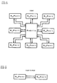
- Ancor Communications-The World's Fastest Network shows three topologies as illustrated in Figs. 1, 2 , and 3 .
- Those three topologies are ones standardized as a fibre channel: a fabric type illustrated in Fig. 1 ; a point-to-point type illustrated in Fig. 2 ; and a loop type illustrated in Fig. 3 .
- a fibre channel fabric acts as a data communication equipment which constitutes fabric topology of the above-mentioned fibre channels. Nodes which play a main role in data communication are connected to a fibre channel fabric in star-like arrangement.
- a conventional fibre channel fabric interchanges a variable length frame as it is, namely, without converting a variable length frame into other forms, resulting in that a control thereof was unavoidable to be quite complicated, and that it was quite difficult or almost impossible to increase the number of nodes connecting thereto, and enhance interchangability thereof.
- Japanese Unexamined Patent Publication No. 5-268255 has suggested a solution to a frame relay exchange system having the same problems as mentioned above.
- the Publication suggests dividing a variable length frame relay packet into fixed length ATM (Asynchronous Transfer Mode) cells, to thereby exchange cells for enhancement of interchangability.
- ATM Asynchronous Transfer Mode
- ATM characteristics make it difficult to avoid cell loss caused by congestion.
- Japanese Unexamined Patent Publication No. 7-202903 has suggested a system where a frame relay packet is converted into cells by utilizing cell loss priority control identifier for ATM.
- a fibre channel has connection-oriented calling setup, which is called “class 1 service” in the fibre channel standard, and a connectionless calling setup, which is called “class 2 or 3 service” in the fibre channel standard. If the above-mentioned prior art were applied to the connectionless calling setup, a fabric would have to carry out ATM calling setup/releasing command each time when a communication of one frame of a fibre channel is made.
- Fig. 4 illustrates a calling setup/releasing command sequence for B-ISDN (Broadband aspects of ISDN) which is typical communication network utilizing ATM and is recommended as Q.2931 by ITU-T (International Telecommunication Union-Telecommunication Standardization Sector).
- B-ISDN Broadband aspects of ISDN
- ITU-T International Telecommunication Union-Telecommunication Standardization Sector
- a fibre channel fabric needs to have a calling setup system which is capable of high speed operation and being constructed in simpler configuration, and which is not dependent on ATM calling setup system.
- the prior art fibre channel fabric interchanges a variable length frame as it is, namely without converting into other forms
- the prior art fibre channel fabric is accompanied with problems that the control therefor is quite complicated, and that it is quite difficult or almost impossible to increase the number of nodes to be connected to the fibre channel fabric, and enhance interchangability thereof.
- a conventional system where a variable length data is interchanged by dividing into fixed length cells such as ATM has a problem that when a system for interchanging original variable length data is a connectionless one, an overhead concerned with calling setup is quite great, and hence interchangability is deteriorated to much degree.
- the reason is as follows. If original variable length data is connection-oriented, it would be possible to cause a time necessary for ATM calling setup to be contained in a time necessary for calling setup of the original variable length data, and it would be also possible to carry out data exchange after calling setup at higher speed by virtue of conversion into fixed length cells.
- a time necessary for calling setup is added to exchange time as an increase.
- the congestion control system suggested in a system where a frame relay packet is converted into cells requests a cell to be produced in accordance with ATM standards.
- a cell were to be produced not in accordance with ATM standards, it was necessary to have another congestion control system in place of the above-mentioned one.
- the reason is that partial cell loss caused by congestion results that original variable length frame is unable to be reconstructed after cell exchanges, regardless of whether data is connection-oriented or not, and hence it is absolutely necessary to have any means for avoiding cell loss or means for detection and recovery.
- Japanese Unexamined Patent Publication No. 62-155648 based on U.S. patent application No. 773380 filed on September 6, 1985 by Jonathan Seals Turner and assigned to Washington University, has suggested a packet switch apparatus, and a method of distributing a copy of data packet to a plurality of addresses.
- Japanese Unexamined Patent Publication No. 7-321824 based on U.K. patent application No. 94303118.7 filed on April 28, 1994 by Hewlett Packard Company, has suggested a chip used for cell switch fabric.
- the Publication suggests an integrated circuit chip which is applicable to cell switch fabrics having various structures and which is capable of interfacing a cell memory with N input and output ports.
- Japanese Unexamined Patent Publication No. 6-335038 based on U.S. patent application No. 58185 filed on May 10, 1993 by Lawrence Baranye and assigned to American Telephone and Telephone Company, has suggested a method of replacing interchange fabrics in a data communication equipment.
- Japanese Unexamined Patent Publication No. 61-501814 based on U.S. patent application No. 597508 ( PCT/US85/00557 ) filed on April 6, 1984 by Royal M. Larthon et al. and assigned to American Telephone and Telephone Company, has suggested multiplexed interconnection in packet interchange node package.
- Japanese Unexamined Patent Publication No. 6-350651 has suggested a hybrid type data processing apparatus which can process a packet signal, a frame relay signal, and ATM cell.
- Japanese Unexamined Patent Publication No. 6-45944 has suggested an apparatus for encoding and decoding variable rate, which is capable of keeping quality in encoding and decoding data even if input data varies in an amount.
- Japanese Unexamined Patent Publication No. 4-291548 has suggested a matrix type time sharing label interchange system where variable length and fixed length frames are contained in a common interchange device to thereby carry out uniform interchange.
- Another object of the present invention is to provide a fibre channel fabric, acting as a variable length frame interchange equipment utilizing a fixed length cell conversion system such as ATM, which provides a simply structured congestion control.
- a fibre channel fabric comprising : (a) a fibre channel interface controller for communicating with a termination node or another fibre channel fabric to control a fibre channel in protocol, (b) an input data buffer for temporarily storing a frame received from the termination node or the other fibre channel fabric, (c) a cell producer for dividing the thus received frame into fixed length cells, (d) a cell switch for interchanging data at the unit of a fixed length cell, (e) a frame constructor for reconstructing an original frame of the fixed length cells transmitted from the cell switch, (f) an output data buffer for temporarily storing a frame transmitted from the frame constructor, and (g) a congestion controller for monitoring a load exerted on the cell switch to thereby avoid congestion.
- the cell producer includes (a) an address header producer for converting address data contained in a frame of a fibre channel into internal address data required for the cell switch to carry out cell interchanges, (b) a cell numeral producer for producing sequence numerals for cells, which are necessary for detecting cell loss, (c) a frame division controller for adding both an address header produced by the address header producer and the cell sequence numeral produced by the cell numeral producer into a fragment of a frame taken out of the input data buffer to thereby produce a fixed length cell, and transferring the thus produced fixed length cell to the cell switch, and (d) an output buffer requiring device for cooperating with the congestion controller to manage operation status of the output data buffer, and control operation timing of the frame division controller so that a load over a predetermined magnitude is not exerted on the cell switch.
- the address header producer includes (a) an address identifier storing device for storing an address identifier of an input frame, and (b) an address converter for receiving an output transmitted from the address identifier storing device, and transmitting an internal address identifier in a fabric to the cell switch.
- the address header producer may be designed to include (a) an address identifier storing device for storing an address identifier of an input frame, (b) a comparator for comparing an output transmitted from the address identifier storing device with an address identifier transmitted to the fibre channel, (c) a first address converter for receiving a part of an output transmitted from the address identifier storing device, and transmitting an internal address identifier in a fabric to the cell switch, (d) a second address converter for receiving another part of an output transmitted from the address identifier storing device, and transmitting an internal address identifier in a fabric to the cell switch, and (e) a selector for selecting and transmitting one of outputs transmitted from the first and second address converter in accordance with a result of comparison carried out by the comparator.
- the fibre channel fabric may further include an address header register for storing data read out of the address converter, the data making an address header.
- the frame constructor includes (a) a cell header remover for removing cell control data including an address header, out of a cell transferred from the cell switch to thereby extract a fragment of a frame of a fibre channel, and transmitting the thus extracted fragment to the output data buffer, and (b) a cell numeral monitor for detecting whether cell loss occurs by monitoring an order of cells received from the cell switch.
- the fibre channel fabric may further include an address header register for storing the one of outputs transmitted from the first and second address converters.
- the frame constructor includes (a) a cell header remover for removing cell control data including an address header, out of a cell transferred from the cell switch to thereby extract a fragment of a frame of a fibre channel, and transmitting the thus extracted fragment to the output data buffer, and (b) a cell numeral monitor for detecting whether cell loss occurs by monitoring an order of cells received from the cell switch by virtue of the cell sequence numeral contained in a cell.
- the congestion controller includes (a) a flag register having the bit number equal to the number of I/O ports, and (b) a bus arbitrating and controlling device for receiving access requirements transmitted from the cell producer and the frame constructor to the flag register, arbitrating the access requirements and transmitting arbitration results to a requester, and controlling address/data bus through which the cell producer and the frame constructor are communicated with the flag register, in accordance with the arbitration results, to thereby control writing to and reading out of the flag register.
- the input data buffer may be designed to have a function of absorbing a difference between a communication rate of a fibre channel and a cell interchange rate in the cell switch.
- the frame constructor may be designed to, when receiving a final cell constituting a frame, extract data necessary for a fibre channel frame out of effective data contained in control data of the final cell.
- the output data buffer may be designed to have a function of absorbing a difference between a communication rate of a fibre channel and a cell interchange rate in the cell switch.
- the cell numeral producer may be designed to include (a) a port identifier register for retaining a port number of a fibre channel, and (b) a counter countable up to a predetermined number, the counter being initialized prior to frame division accomplished by the frame division controller.
- the counter may be incremented each time when a cell is transferred, and apply the thus obtained number to the cell as a cell numeral.
- the address converter, the first and second address converters may be constituted of a static random access memory (SRAM).
- SRAM static random access memory
- the fibre channel fabric in accordance with the present invention accomplishes calling setup/releasing command and congestion control frame by frame in simple structure, which are not dependent on ATM standards. Hence, it is now possible to constitute a connectionless, variable length frame type data communication equipment of a fixed length cell interchange device such as ATM switch device.
- An interchange system using a fixed length cell is more readily constructed as a hardware than an interchange system using a variable length frame, and can be constructed in a hardware having a simpler structure. Hence, the interchangability of the fixed length cell interchange system can be readily enhanced.
- the interchangability Q of a whole fibre channel fabric is represented with the following equation.
- Q data tranfer rate per one I / O port ⁇ the number of I / O ports
- enhancement in the interchangability means an increase in the number of I/O ports having the same data transfer rate.
- the present invention provides enhancement in interchangability of a fibre channel fabric, and an increase in the number of nodes to be connected thereto.
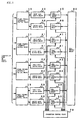
- a fibre channel fabric in accordance with a preferred embodiment of the present invention includes a plurality of fibre channel interface control means 10, 11, 12 and 13, a plurality of input data buffer means 20, 21, 22 and 23, a plurality of output data buffer means 30, 31, 32 and 33, a plurality of cell producing means 40, 41, 42 and 43, a plurality of frame constructing means 50, 51, 52 and 53, cell switch means 60 for controlling the above-mentioned means, and congestion controlling means 70.
- one fibre channel interface control means 10, one input data buffer means 20, one output data buffer means 30, one cell producing means 40, and one frame constructing means 50 cooperate with one another to thereby form a fabric to which either a single termination node or a single another fabric is connected.
- the fibre channel fabric illustrated in Fig. 5 is a fabric to which four termination nodes or other fabrics can be connected.
- the greater number of termination nodes or other fabrics may be connected to the illustrated fibre channel fabric.
- the fibre channel interface control means 10 to 13 control communication of a frame of a fibre channel to be made with a termination node or other fabrics, in accordance with ANSI standards.
- the control accomplished by the fibre channel interface control means 10 to 13 includes flow control and class service control.
- the fibre channel interface control means 10 to 13 are able to control transmitting a frame simultaneously with receiving a frame. That is, the fibre channel interface control means 10 to 13 accomplish full duplex communication in accordance with fibre channel standards.
- the input data buffer means 20 to 23 temporarily store a frame received from a termination node or other fabrics.
- the input data buffer means 20 to 23 are designed to have a function of absorbing a difference between a communication rate on a fibre channel and a cell interchange rate in the cell switch means 60. Accordingly, memory capacity of the input data buffer means 20 to 23 is determined based on a relation among a communication rate on a fibre channel, a cell interchange rate in the cell switch means 60, and a maximum frame length of a fibre channel.
- the output data buffer means 30 to 33 temporarily store a fragment of a frame transmitted from the cell switch means 60.
- the output data buffer means 30 to 33 are designed to have a function of absorbing a difference between a communication rate on a fibre channel and a cell interchange rate in the cell switch means 60. Accordingly, memory capacity of the output data buffer means 30 to 33 is determined based on a relation among a communication rate on a fibre channel, a cell interchange rate in the cell switch means 60, and a maximum frame length of a fibre channel.
- the cell producing means 40 to 43 divide a frame of a fibre channel into fixed length cells to which the cell switch means 60 can carry out cell interchange.
- the cell producing means 40 to 43 provide a cell with information indicating effective data contained in a last cell in a frame.
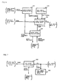
- Fig. 6 illustrates an example of a structure of the cell producing means 40 to 43.
- Each of the cell producing means 40 to 43 includes address header producing means 410, cell numeral producing means 420, frame division control means 430, and output buffer requiring means 440.
- the address header producing means 410 converts address data contained in a frame of a fibre channel into internal address data necessary for the cell switch means 60 to carry out cell interchange.
- the cell numeral producing means 420 produces a cell sequence numeral necessary for detecting cell loss.
- the frame division control means 430 adds both an address header produced by the address header producing means 410 and a cell numeral produced by the cell numeral producing means 420 into a fragment of a frame taken out of the input data buffer means 20 to 23 to thereby produce a fixed length cell, and transfers the thus produced fixed length cell to the cell switch means 60.
- a size of a cell is determined in dependence on specification of the cell switch means 60.
- the output buffer requiring means 440 cooperates with the congestion controlling means 70 to thereby manage output buffer status, and control operation timing of the frame division control means 430 so that a load over a predetermined magnitude is not exerted on the cell switch means 60.
- the frame constructing means 50 to 53 reconstruct a frame of an original fibre channel on the basis of cells transmitted from the cell switch means 60.
- the frame constructing means 50 to 53 extract data necessary for an original fibre channel frame out of information indicating effective data, contained in control data of the final cell.
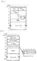
- Fig. 7 illustrates an example of a structure of the frame constructing means 50 to 53. As illustrated, each of the frame constructing means 50 to 53 includes cell header removing means 510 and cell numeral monitoring means 520.
- the cell header removing means 510 removes cell control data such as an address header out of a cell transferred from the cell switch means 60 to thereby extract only a fragment of a frame of an original fibre channel. The thus extracted fragment is transferred to the output data buffer means 30 to 33.
- the cell numeral monitoring means 520 monitors an order of cells received from the cell switch means 60 by virtue of the cell numeral contained in each of cells, to thereby check whether cell loss occurs.
- the cell switch means 60 distributes a cell to an associated one of the frame constructing means 50 to 53 in accordance with an address header contained in each of cells transferred from the cell producing means 40 to 43.
- the congestion control means 70 cooperates with the cell producing means 40 to 43 and the frame constructing means 50 to 53 to thereby manage operation status of the output data buffer means 30 to 33 so as to control a load to be exerted on the cell switch means 60 so that the load does not exceed a critical magnitude.
- Fig. 8 is a block diagram of a fibre channel fabric in accordance with another preferred embodiment of the present invention.
- the fibre channel fabric is comprised of three sections for accomplishing a function.
- the illustrated fibre channel fabric includes fibre channel port sections 100, 101, 102 and 103, ATM switch device 160 which is equivalent to the cell switch means 60, and output buffer status flag control section 170 carrying out congestion management.
- the instant embodiment exemplifies a fibre channel fabric to which totally four termination nodes or other fabrics may be connected. It should be noted that it would be possible for the fibre channel fabric in accordance with the instant embodiment to increase the number of connection nodes merely by adding fibre channel port sections thereto, and replacing the ATM switch device 160 with another ATM switch device which can deal with the increased number of connection nodes.
- the fibre channel port section 100 includes a fibre channel interface control section 110, an input buffer 120, an output buffer 130, a cell producing section 140, and a frame constructing section 150.
- the fibre channel interface control section 110, the input buffer 120, the output buffer 130, the cell producing section 140, and the frame constructing section 150 correspond in function to the fibre channel interface control means 10, the input data buffer means 20, the output data buffer means 30, the cell producing means 40, and the frame constructing means 50 all illustrated in Fig. 5 , respectively.
- the cell producing section 140 includes an address header producing section 141, a cell numeral producing section 142, a frame division control section 143, and an output buffer requirement control section 144.
- the address header producing section 141, the cell numeral producing section 142, the frame division control section 143, and the output buffer requirement control section 144 correspond in function to the address header producing means 410, the cell numeral producing means 420, the frame division control means 430, and the output buffer requiring means 440 all illustrated in Fig. 6 , respectively.
- the cell numeral producing section 142 includes a port identifier register 1421 for retaining a port number of the associated fibre channel port section, and a counter 1422 countable up to 45.
- the counter 1422 is initialized to "1" prior to frame division accomplished by the frame division control section 143.
- the frame constructing section 150 includes a cell header removal controlling section 151, and a cell numeral monitoring section 152.
- the cell header removal controlling section 151 and the cell numeral monitoring section 152 correspond in function to the cell header removing means 510 and the cell numeral monitoring means 520 both illustrated in Fig. 7 , respectively.
- the other fibre channel port sections 101, 102 and 103 have the same structure as that of the fibre channel port section 100.
- the cell producing section 140 and the frame constructing section 150 both mounted on each one of the fibre channel port sections 100 to 103 are connected to the output buffer status flag control section 170 through a congestion control bus 180, as illustrated in Fig. 8 .
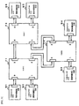
- Figs. 9 and 10 illustrate examples of computer systems employing the fibre channel fabric in accordance with the instant embodiment.
- Fig. 9 illustrates an example of a computer system comprising four termination nodes N1 to N4 and the fibre channel fabric F1 in accordance with the instant embodiment, illustrated in Fig. 8
- Fig. 10 illustrates an example of a computer system comprising six termination nodes N1 to N6 and three fibre channel fabrics F1 to F3 in accordance with the instant embodiment, illustrated in Fig. 8 .
- the fibre channel fabric illustrated in Fig. 8 corresponds to the fabric F1 in the computer system illustrated in Fig. 9 ;
- each one of the termination nodes N1 to N4 is connected to the fabric channel interface control section 110 in each one of the fibre channel port sections 100 to 103 of the fabric F1; and
- the termination node N1 transmits one frame to the termination node N4 under the class 2 transfer mode.
- the class 2 transfer mode in a fibre channel is a mode where data frame transfer is accomplished without carrying out calling setup between termination nodes (in the example described hereinbelow, between the termination nodes N1 and N4) prior to data frame transfer.
- 3-byte node ID unique in the computer system is assigned to each one of the termination nodes N1 and N2 of a fibre channel.
- an address of a frame is identified with the node ID.
- the node ID is assigned to the termination nodes N1 to N4 by the fabric F1 in accordance with an inherent sequence called fabric log-in, when the computer system starts.
- Each one of the termination nodes can know the node ID of other termination nodes connected thereto through the fabric F1, by virtue of a sequence called node log-in.
- the termination node N1 transfers a frame to the termination node N4 under class 2
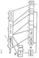
- the termination node N1 forms a frame where the node ID of the termination node N4 is arranged in 3 byte DID (Destination Identifier) field 610 located in a frame header 600 of a frame of a fibre channel illustrated in Fig. 11 .
- the frame is transferred to the fabric F1 in accordance with fibre channel standard.
- the thus transferred frame is received in the interface control section 110 of the fibre channel port section 100 associated with the termination node N1 of the fabric F1.
- the fibre channel interface control section 110 stores the thus received frame in the input buffer 120, and at the same time, takes DID 610 out of a frame header 600 of the frame, and informs the DID of the address header producing section 141 in the cell producing section 140.
- the address header producing section 141 converts the DID (which is "4" in the instant embodiment) of the termination node N4 into an address header to be transmitted to the ATM switch device 160, in accordance with a predetermined algorithm, and instructs the output buffer requirement control section 144 to start operation.
- the output buffer requirement control section 144 checks, through the congestion control bus 180, status of the output buffer 130 of the fibre channel port section 103 associated with the termination node N4. If the output buffer 130 were found to be usable, the output buffer requirement control section 144 causes the frame division control section 143 to start.
- the frame division control section 143 transfers the following data (a) to (e) to ATM switch device 160 in order: (a) an address header retained in the address header producing section 141; (b) an input port numeral (herein, which is "1" indicating the fibre channel port section 100) retained in the port ID register 1421 of the cell numeral producing section 142; (c) a cell numeral produced by the cell numeral producing section 142; (d) effective data information and 2 byte dummy data both managed by the frame division control section 143; and (e) 48 byte data at the head of a frame taken out of the input buffer 120.
- an address header retained in the address header producing section 141
- an input port numeral herein, which is "1" indicating the fibre channel port section 100
- Fig. 12 illustrates an original format of ATM cell
- Fig. 13 illustrates a format of a cell to be transferred to ATM switch device 160.
- ATM switch device does not interpret address data represented with VPI/VCI in ATM header, but carry out cell interchange control by employing an address header added to a head of a cell.
- the address header corresponds to an address header at zero-th byte in Fig. 13 .
- a size of an address header and a data format are dependent on ATM device used.
- ATM switch employing one byte address header is to be used, but it should be noted that even if address header formats were different, such a difference might be eliminated merely by changing conversion algorithm of the address header producing section 141.
- the above-mentioned 1 byte input port numeral is transferred to ATM switch device 160 in order to collect fault data when defect such as cell loss is detected.
- the 1 byte input port numeral may be omitted from data to be transferred to ATM switch device 160.
- the frame division control section 143 is informed of a frame length from the fibre channel interface control section 110 in a predetermined manner, and divides a frame of a fibre channel starting from SOF (Start of Frame) and ending at EOF (End of Frame) into 48 byte sections in ATM payload in accordance with the informed frame length.
- the thus divided frame is transferred to ATM switch device 160 in turn.
- the frame division control section 143 transfers all the divided frames to ATM switch device 160, the frame division control section 143 transmits a signal indicating that to the fibre channel interface control section 110.
- the fibre channel interface control section 110 receiving the signal informs the termination node N1 in accordance with fibre channel standard that the termination node N1 is allowed to receive a next frame.
- the frame division control section 143 produces information indicating effective data relating to a final cell in the divided cell, and buries the information in the third byte in a cell, namely effective data information field. For instance, if the termination node N1 transfers a frame including 48 byte data in the instant embodiment, a frame length would be 48 byte. The frame is divided into two cells, in which a second or final cell is 36 byte long. However, since ATM switch device 160 carries out cell interchange at the unit of a cell having fixed length of 54 byte including an address header, the frame division control section 143 is required to design the final cell to be 54 byte long.
- the frame division control section 143 would have to fill 12 byte located at a trailing end of payload with dummy data 620.
- data for removing the dummy data 620 when a frame is constructed it is indicated in the effective data information field in Fig. 13 that effective data is 36 byte long.
- a flag in the effective data information field for indicating whether a cell in question is a final one.
- the flag is used to distinguish a final cell from non-final cells when effective data in a final cell is 48 byte long.
- the frame division control section 143 always buries 48 byte data in an effective data information field thereof, and produces a cell in which a final cell indicating flag is turned off.
- the cell numeral producing section 142 causes the counter 1422 to make an increment each time when a cell is transferred from the time when a frame is started to be divided, and assigns the thus obtained counter value to a cell in question as a cell numeral.
- each of cells is assigned a cell numeral which indicates an order in an original frame.
- Each of cells having the thus assigned cell numeral is cell-interchanged in ATM switch device 160 in accordance with an address header, and is transmitted to the frame constructing section 150 associated with the address. In the instant embodiment, the thus interchanged cell is transmitted to the frame constructing section 150 of the fibre channel port section 103 associated with the termination node N4.
- the cell header removing control section 151 constituting the frame constructing section 150 removes six bytes, from the zero-th to fifth bytes, of ATM cell illustrated in Fig. 13 , and stores the rest, namely 48 bytes in the payload, in the output buffer 130.
- the cell header removing control section 151 monitors the effective data information field, and, when the final cell flag is on, stores the payload in the output buffer 130 in a degree indicated by the effective data length.
- the cell header removing control section 151 informs the fibre channel interface control section 110 that the payload has started to be stored in the output buffer 130. Then, the fibre channel interface control section 110 informed of the above transfers data stored in the output buffer 130 to the termination node N4.
- the cell numeral monitoring section 152 monitors cell numerals of cells transmitted from the ATM switch device 160. If the cell numeral monitoring section 152 found that the cell numerals are not in ascending order, the cell numeral monitoring section 152 considers it as occurrence of cell loss, and informs the fibre channel interface control section 110 of the fact so as to request to carry out disposal to abnormal condition in accordance with fibre channel standard.
- the cell header removing control section 151 After the cell header removing control section 151 finishes storing a final cell in the output buffer 130, the cell header removing control section 151 instructs the output buffer status flag control section 170 through the congestion control bus 180 to release the output buffer 130.
- Fig. 15 illustrates a conversion table between DID and an address header.
- DID is a value indicating node ID of a location to which a frame is transferred, contained in the frame of a fibre channel frame.
- Node ID is a unique value assigned to each of termination nodes from a fibre channel fabric when a computer system is started, and specific content of the value is determined by the fibre channel fabric. Since four termination nodes or other fabrics at greatest may be connected to the fibre channel fabric in accordance with the instant embodiment, four unique values at greatest may be determined as node IDs (NID).
- NID node IDs
- numerals 0 to 3 are assigned to node IDs of the termination nodes, and there are prepared conversion tables for each one of the node IDs.
- Each one of the conversion tables is associated with an address header of ATM cell.
- a 1 byte address header is to be used.
- Fig. 14 illustrates an example of a structure of the address header producing section 141.
- the address header producing section 141 includes a DID register 1411, an address header conversion table 1412, and an address header register 1413.
- the DID register 1411 stores therein DID of a received frame, transmitted from the fibre channel interface control section 110.
- the instant embodiment utilizes only a lowermost byte (strictly, only lowermost two bits) among 3 bytes DID.
- Data which will make an address header is read out of the address header conversion table 1412 with the lowermost byte being used as an address. The thus read out data is stored in the address header register 1413.
- the address header conversion table 1412 may be constituted of static random access memory (SRAM).
- the frame division control section 143 of a fibre channel fabric produces a cell by adding data stored in the address header register 1413 to address header fields of all of cells.
- the above-mentioned instant embodiment is in particular suitable to a system illustrated in Fig. 9 where only termination nodes are connected to a fabric, and provides an advantage that calling setup can be carried out frame by frame at high speed by means of a quite simple structure.
- the instant embodiment provides an additional advantage that it is no longer necessary to carry out calling release.
- address header register 1413 is added to the address header producing section 141 merely for more proper operation, and that the address header register 1413 may be omitted.
- the address header conversion table 1412 may be designed to transmit an output thereof directly to the frame division control section 143 not through the address header register 1413.
- Fig. 16 illustrates an example of a conversion table for a case where address headers of ATM switch device are 2 bytes, and values of the address headers are not in simple ascending order. Even such ATM switch device might be readily used simply by changing a conversion table or an address header conversion table.
- the instant example is in particular suitable to calling setup control of a fibre channel fabric in a computer system including a plurality of fibre channel fabrics, illustrated in Fig. 10 .
- calling setup control for a computer system where three fabrics F1 to F3 are connected to one another, and totally six termination nodes N1 to N6 are connected to fibre channel ports which are not used for connecting fabrics to each other.
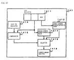
- Fig. 17 illustrates another example of a structure of the address header producing section 141.
- the illustrated address header producing section 141 includes DID register 1411, a first address header conversion table 1412, an address header register 1413, a self-ID register 1414, a comparator 1415, a selector 1416, and a second address header conversion table 1417.
- the DID register 1411, the first address header conversion table 1412 and the address header register 1413 have the same function as that of the corresponding elements of the address header producing section 141 illustrated in Fig. 14 .
- the address header producing section 141 in Fig. 17 assigns fabric ID (FID) for identifying a fabric to second byte in DID, assigns node ID (NID) for identifying a termination node to third byte in DID, and does not use first byte in DID.
- Each of the first address header conversion tables 1412 in the fabrics F1 to F3 is comprised of a conversion table such as one illustrated in Fig. 15 .
- the self-ID register 1414 stores FID of a fabric to which the self-ID register 1414 belongs.
- the comparator 1415 compares FID of DID register 1411 to a value of the self-ID register 1414, and informs comparison results of the selector 1416.
- the selector 1416 stores one of outputs from the first address header conversion table 1412 and the second address header conversion table 1417 in the address header register 1413 in accordance with the comparison results transmitted from the comparator 1415.
- the second address header conversion tables 1417 in the fabrics F1 to F3 are designed to have conversion tables illustrated in Figs. 18A to 18C , respectively.
- the fabric F1 stores DID of a frame received from the termination node N1 in the DID register 1411. Then, the comparator 1415 compares FID stored in second byte in DID to a value of the self-ID register 1414 storing FID of the fabric F1 therein. Since the termination node N2 to which a frame is to be transmitted is connected to the fabric F1 to which the termination node N1 from which a frame is to be transmitted to the termination node N2 is connected, the comparator 1415 outputs a comparison result indicating that they are coincident with each other. As a result, the selector 1416 selects an output transmitted from the first address header conversion table 1412, and stores the thus selected output in the address header register 1413.
- a frame transmitted from the termination node N1 is first received in the fabric F1, and then DID in the received frame is stored in DID register 1411.
- the fabric F1 compares FID of itself to FID of an address termination node contained in DID. Since the termination nodes N1 and N6 are connected to different fabrics, comparison result indicates that they are not coincident. Then, the fabric F1 transmits FID value in second byte in DID register 1411 to the second address header conversion table 1417 as an address, and the selector 1416 stores an output transmitted from the second address header conversion table 1417 in the address header register 1413.
- a conversion table illustrated in Fig. 18A is stored in the second address header conversion table 1417 in the fabric F1.
- the fabric F3 is selected as a fabric to which a frame is to be transmitted.
- a frame transmitted from the termination node N1 is transferred to the fabric F3 through the fabric F1.
- the fabric F3 transfers the frame to the termination node N6 in the same operation as the above-mentioned operation carried out by the fabric F1 for transferring a frame from the termination node N1 to the termination node N2.
- the conversion tables arranged in the second address header conversion tables 1417 of the fabrics F1 to F3 are provided with a transfer path to a fabric, to which a termination node in question is connected, as an address for a frame to be transmitted to a termination node connected to another fabric.
- a termination node to which a frame is to be finally transmitted belongs to another fabric which is not directly connected to a fabric receiving a frame, it would be possible to construct multiple connection of fabrics by arranging a path leading to an intermediate fabric which in turn leads to an address termination node. For instance, when the termination node N1 transmits a frame to the termination node N2 in a computer system illustrated in Fig. 19 , the fabric F1 in advance prepares a conversion table so as to transfer the frame to the fabric F2.
- the calling setup control having been explained so far with reference to Figs. 17 and 18A-18C provides an advantage that calling setup control can be carried out with a simply structured hardware even in a computer system having a plurality of fabrics and a plurality of termination nodes.
- Fig. 20 illustrates an example of a structure of the output buffer status flag control section 170.
- the output buffer status flag control section 170 comprises a bus arbitration control section 171, and an output buffer status flag register 172.
- the output buffer status flag resister 172 is a totally four bits register addressed by two bits per a bit.
- the bus arbitration control section 171 receives requirements for buffer requirement control b01 to b04 transmitted from the cell producing section 140, and requirements for buffer release control b05 to b08 transmitted from the frame constructing section 150, and transmits allowances for using a bus b11 to b18 in response to the eight requirements b01 to b08. Both a 2 bits address bus 181 and a 1 bit data bus 182 are connected to the output buffer status flag register 172. A control for writing into and reading out of the output buffer status flag register 172 is carried out by the bus arbitration control section 171.
- the cell producing section 140 of the fibre channel port section 100 corresponding to the termination node N1 checks a status of the output buffer 130 to which a frame or cell is to be transmitted, namely the output buffer 130 of the fibre channel port section 103 corresponding to the termination node N4, the cell producing section 140 first drives the requirement for buffer requirement control b01 to thereby notify the bus arbitration control section 171.
- the bus arbitration control section 171 arbitrates the requirements for buffer requirement control b01 to b04 and the requirements for buffer release control b05 to b08 in accordance with a predetermined algorithm. As a result, if the cell producing section 140 which transmitted the requirement for buffer requirement control b01 obtains an allowance for using the output buffer status flag register 172, the bus arbitration control section 171 notifies an allowance b11 for using a bus of the requester, namely the cell producing section 140.
- the requestor or cell producing section 140 receiving a response from the bus arbitration control section 171 informs a binary digit "11" (see Fig. 21 ) of the address bus 181.
- the binary digit "11” is an address indicating the output buffer 130 of the fibre channel port section 103 which the cell producing section 140 is going to use.
- the cell producing section 140 concurrently informs a binary digit "1" of the data bus 182.
- the binary digit "1" is data indicating buffer requirement.
- the bus arbitration control section 171 checks the status of the address bus 181 and the data bus 182 to thereby know that requirement for the output buffer 130 of the fibre channel port section 103 is transmitted from the cell producing section 140, the bus arbitration control section 171 checks a value of a bit of an associated binary digit address "11" in the output buffer status flag register 172. If the checked bit is equal to "0" in a binary digit, the bus arbitration control section 171 replaces the binary digit "0" with a binary digit "1", and notifies the binary digit "0" of the requestor or cell producing section 140 through the data bus 182.
- the bus arbitration control section 171 notifies the binary digit "1" of the requestor or cell producing section 140 through the data bus 182.
- a binary digit "0" in the output buffer status flag register 172 means that the output buffer is allowed to be used, and a binary digit "1" means that the output buffer is not allowed to be used.
- the requirements for buffer release control take precedence of all the requirements for buffer requirement control. Hence, it is ensured that the requirements for buffer release control b05 to b08 are first processed when the requirements for buffer requirement control b01 to b04 and the requirements for buffer release control b05 to b08 are transmitted concurrently, resulting in reduction in occurrence rate of congestion.
- the output buffer is not allowed to be concurrently used for constructing a plurality of frames, which ensures that confusion in a cell is avoided, and that an excessive load is not exerted on ATM switch device 160.
- a load unavoidable even by the above-mentioned congestion control may be exerted on ATM switch device with the result of occurrence of cell loss.
Description
- The invention relates to a fabric for a fibre channel which is one of data communication standards standardized as X3T11 by American National Standard for Information Systems (ANSI), and more particularly to a fibre channel fabric which is capable of higher speed operation and a greater number of nodes.
- A fibre channel, which is one of data communication standards standardized by ANSI as an I/O channel of computer system or communication medium for local area network (LAN), is characterized by making data communication at the unit of a variable length frame having 2148 bytes at maximum including header and other control data, having various flow control functions and a calling control function which is called class service, and being able to construct a flexible communication system in line with various applications.
- For instance, Ancor Communications-The World's Fastest Network, a version updated on June 17, 1996, shows three topologies as illustrated in
Figs. 1, 2 , and3 . Those three topologies are ones standardized as a fibre channel: a fabric type illustrated inFig. 1 ; a point-to-point type illustrated inFig. 2 ; and a loop type illustrated inFig. 3 . A fibre channel fabric acts as a data communication equipment which constitutes fabric topology of the above-mentioned fibre channels. Nodes which play a main role in data communication are connected to a fibre channel fabric in star-like arrangement. - A conventional fibre channel fabric interchanges a variable length frame as it is, namely, without converting a variable length frame into other forms, resulting in that a control thereof was unavoidable to be quite complicated, and that it was quite difficult or almost impossible to increase the number of nodes connecting thereto, and enhance interchangability thereof.
- For instance,
Japanese Unexamined Patent Publication No. 5-268255 Japanese Unexamined Patent Publication No. 7-202903 - However, since calling setup is basically connection-oriented in a frame relay, a frame relay has high affinity with ATM. Accordingly, it is expected that the above-mentioned Publications can enhance interchangability, but the above-mentioned prior art is not applicable to a fibre channel, as mentioned below.
- That is, a fibre channel has connection-oriented calling setup, which is called "
class 1 service" in the fibre channel standard, and a connectionless calling setup, which is called "class -
Fig. 4 illustrates a calling setup/releasing command sequence for B-ISDN (Broadband aspects of ISDN) which is typical communication network utilizing ATM and is recommended as Q.2931 by ITU-T (International Telecommunication Union-Telecommunication Standardization Sector). - With reference to
Fig. 4 , in a system where ATM calling setup and releasing command are carried out each time before and after one frame having about 2000 bytes at maximum is interchanged, an overhead required for calling setup/releasing command is too excessive, resulting in reduction in performance greater than enhancement in interchangability brought by data communication utilizing fixed length cells. Accordingly, a fibre channel fabric needs to have a calling setup system which is capable of high speed operation and being constructed in simpler configuration, and which is not dependent on ATM calling setup system. - For the same reason, the above-mentioned prior art which attempts to avoid cell loss by virtue of ATM congestion control function is not applicable to a fibre channel fabric.
- As having been mentioned so far, since the prior art fibre channel fabric interchanges a variable length frame as it is, namely without converting into other forms, the prior art fibre channel fabric is accompanied with problems that the control therefor is quite complicated, and that it is quite difficult or almost impossible to increase the number of nodes to be connected to the fibre channel fabric, and enhance interchangability thereof.
- In addition, when a technique for enhancement in performance of a frame relay interchange system is to be applied to a fibre channel fabric, problems arise as follows.
- First, a conventional system where a variable length data is interchanged by dividing into fixed length cells such as ATM has a problem that when a system for interchanging original variable length data is a connectionless one, an overhead concerned with calling setup is quite great, and hence interchangability is deteriorated to much degree. The reason is as follows. If original variable length data is connection-oriented, it would be possible to cause a time necessary for ATM calling setup to be contained in a time necessary for calling setup of the original variable length data, and it would be also possible to carry out data exchange after calling setup at higher speed by virtue of conversion into fixed length cells. On the other hand, in a system where calling setup is made frame by frame to a connectionless, variable length frame, a time necessary for calling setup is added to exchange time as an increase.
- Secondly, the congestion control system suggested in a system where a frame relay packet is converted into cells requests a cell to be produced in accordance with ATM standards. Hence, if a cell were to be produced not in accordance with ATM standards, it was necessary to have another congestion control system in place of the above-mentioned one. The reason is that partial cell loss caused by congestion results that original variable length frame is unable to be reconstructed after cell exchanges, regardless of whether data is connection-oriented or not, and hence it is absolutely necessary to have any means for avoiding cell loss or means for detection and recovery.
-
Japanese Unexamined Patent Publication No. 62-155648 U.S. patent application No. 773380 filed on September 6, 1985 by Jonathan Seals Turner and assigned to Washington University, has suggested a packet switch apparatus, and a method of distributing a copy of data packet to a plurality of addresses. -
Japanese Unexamined Patent Publication No. 7-321824 U.K. patent application No. 94303118.7 filed on April 28, 1994 -
Japanese Unexamined Patent Publication No. 6-335038 U.S. patent application No. 58185 filed on May 10, 1993 by Lawrence Baranye and assigned to American Telephone and Telegraph Company, has suggested a method of replacing interchange fabrics in a data communication equipment. -
Japanese Unexamined Patent Publication No. 61-501814 U.S. patent application No. 597508 (PCT/US85/00557 ) filed on April 6, 1984 by Royal M. Larthon et al. and assigned to American Telephone and Telegraph Company, has suggested multiplexed interconnection in packet interchange node package. -
Japanese Unexamined Patent Publication No. 6-350651 -
Japanese Unexamined Patent Publication No. 6-45944 -
Japanese Unexamined Patent Publication No. 4-291548 - Related art to the present application may include
European Patent Application No. 0 697 801 A2 which provides a translator for sending fibre channel frames of data from a fibre channel fabric to an ATM network. - In view of the above-mentioned problems of the prior art, it is an object of the present invention to provide a fibre channel fabric, acting as a variable length frame interchange equipment having a connectionless interchange system in a fibre channel, which can be readily constructed as hardware.
- Another object of the present invention is to provide a fibre channel fabric, acting as a variable length frame interchange equipment utilizing a fixed length cell conversion system such as ATM, which provides a simply structured congestion control.
- There is provided a fibre channel fabric comprising : (a) a fibre channel interface controller for communicating with a termination node or another fibre channel fabric to control a fibre channel in protocol, (b) an input data buffer for temporarily storing a frame received from the termination node or the other fibre channel fabric, (c) a cell producer for dividing the thus received frame into fixed length cells, (d) a cell switch for interchanging data at the unit of a fixed length cell, (e) a frame constructor for reconstructing an original frame of the fixed length cells transmitted from the cell switch, (f) an output data buffer for temporarily storing a frame transmitted from the frame constructor, and (g) a congestion controller for monitoring a load exerted on the cell switch to thereby avoid congestion.
- It is preferable that the cell producer includes (a) an address header producer for converting address data contained in a frame of a fibre channel into internal address data required for the cell switch to carry out cell interchanges, (b) a cell numeral producer for producing sequence numerals for cells, which are necessary for detecting cell loss, (c) a frame division controller for adding both an address header produced by the address header producer and the cell sequence numeral produced by the cell numeral producer into a fragment of a frame taken out of the input data buffer to thereby produce a fixed length cell, and transferring the thus produced fixed length cell to the cell switch, and (d) an output buffer requiring device for cooperating with the congestion controller to manage operation status of the output data buffer, and control operation timing of the frame division controller so that a load over a predetermined magnitude is not exerted on the cell switch.
- It is also preferable that the address header producer includes (a) an address identifier storing device for storing an address identifier of an input frame, and (b) an address converter for receiving an output transmitted from the address identifier storing device, and transmitting an internal address identifier in a fabric to the cell switch. The address header producer may be designed to include (a) an address identifier storing device for storing an address identifier of an input frame, (b) a comparator for comparing an output transmitted from the address identifier storing device with an address identifier transmitted to the fibre channel, (c) a first address converter for receiving a part of an output transmitted from the address identifier storing device, and transmitting an internal address identifier in a fabric to the cell switch, (d) a second address converter for receiving another part of an output transmitted from the address identifier storing device, and transmitting an internal address identifier in a fabric to the cell switch, and (e) a selector for selecting and transmitting one of outputs transmitted from the first and second address converter in accordance with a result of comparison carried out by the comparator.
- The fibre channel fabric may further include an address header register for storing data read out of the address converter, the data making an address header.
- It is preferable that the frame constructor includes (a) a cell header remover for removing cell control data including an address header, out of a cell transferred from the cell switch to thereby extract a fragment of a frame of a fibre channel, and transmitting the thus extracted fragment to the output data buffer, and (b) a cell numeral monitor for detecting whether cell loss occurs by monitoring an order of cells received from the cell switch.
- The fibre channel fabric may further include an address header register for storing the one of outputs transmitted from the first and second address converters.
- It is preferable that the frame constructor includes (a) a cell header remover for removing cell control data including an address header, out of a cell transferred from the cell switch to thereby extract a fragment of a frame of a fibre channel, and transmitting the thus extracted fragment to the output data buffer, and (b) a cell numeral monitor for detecting whether cell loss occurs by monitoring an order of cells received from the cell switch by virtue of the cell sequence numeral contained in a cell.
- It is preferable that the congestion controller includes (a) a flag register having the bit number equal to the number of I/O ports, and (b) a bus arbitrating and controlling device for receiving access requirements transmitted from the cell producer and the frame constructor to the flag register, arbitrating the access requirements and transmitting arbitration results to a requester, and controlling address/data bus through which the cell producer and the frame constructor are communicated with the flag register, in accordance with the arbitration results, to thereby control writing to and reading out of the flag register.
- For instance, the input data buffer may be designed to have a function of absorbing a difference between a communication rate of a fibre channel and a cell interchange rate in the cell switch. The frame constructor may be designed to, when receiving a final cell constituting a frame, extract data necessary for a fibre channel frame out of effective data contained in control data of the final cell.
- The output data buffer may be designed to have a function of absorbing a difference between a communication rate of a fibre channel and a cell interchange rate in the cell switch.
- For instance, the cell numeral producer may be designed to include (a) a port identifier register for retaining a port number of a fibre channel, and (b) a counter countable up to a predetermined number, the counter being initialized prior to frame division accomplished by the frame division controller. The counter may be incremented each time when a cell is transferred, and apply the thus obtained number to the cell as a cell numeral.
- For instance, the address converter, the first and second address converters may be constituted of a static random access memory (SRAM).
- The fibre channel fabric in accordance with the present invention accomplishes calling setup/releasing command and congestion control frame by frame in simple structure, which are not dependent on ATM standards. Hence, it is now possible to constitute a connectionless, variable length frame type data communication equipment of a fixed length cell interchange device such as ATM switch device.
- An interchange system using a fixed length cell is more readily constructed as a hardware than an interchange system using a variable length frame, and can be constructed in a hardware having a simpler structure. Hence, the interchangability of the fixed length cell interchange system can be readily enhanced.
- The interchangability Q of a whole fibre channel fabric is represented with the following equation.

- Hence, enhancement in the interchangability means an increase in the number of I/O ports having the same data transfer rate.
- Thus, the present invention provides enhancement in interchangability of a fibre channel fabric, and an increase in the number of nodes to be connected thereto.
-
-
Fig. 1 is a block diagram illustrating a topology of a fabric type fibre channel. -
Fig. 2 is a block diagram illustrating a topology of a point-to-point type fibre channel. -
Fig. 3 is a block diagram illustrating a topology of a loop type fibre channel. -
Fig. 4 is a sequence diagram illustrating calling setup/releasing sequence in B-ISDN. -
Fig. 5 is a block diagram of a fibre channel fabric in accordance with a preferred embodiment of the present invention. -
Fig. 6 is a block diagram of cell producing means in the preferred embodiment. -
Fig. 7 is a block diagram of frame constructing means in the preferred embodiment. -
Fig. 8 is a block diagram of a fibre channel fabric in accordance with another preferred embodiment of the present invention. -
Fig. 9 is a block diagram of a computer system including a fibre channel fabric in accordance with the another preferred embodiment of the present invention. -
Fig. 10 is a block diagram of another computer system including a fibre channel fabric in accordance with the another preferred embodiment of the present invention. -
Fig. 11 is a schematic view showing a relation between frame format of a fibre channel and a cell. -
Fig. 12 is a schematic view illustrating ATM cell format. -
Fig. 13 is a schematic view illustrating a format of a cell used in the another preferred embodiment of the present invention. -
Fig. 14 is a block diagram of cell producing means in the another preferred embodiment of the present invention. -
Fig. 15 illustrates an example of a conversion table arranged in an address header conversion table. -
Fig. 16 illustrates another example of a conversion table arranged in an address header conversion table. -
Fig. 17 is a block diagram of address header producing means in the another preferred embodiment of the present invention. -
Fig. 18A illustrates an example of a conversion table arranged in the second address header conversion table. -
Fig. 18B illustrates another example of a conversion table arranged in the second address header conversion table. -
Fig. 18C illustrates still another example of a conversion table arranged in the second address header conversion table. -
Fig. 19 is a block diagram of still another computer system including a fibre channel fabric in accordance with the another preferred embodiment of the present invention. -
Fig. 20 is a block diagram of an output buffer status flag controller in the another preferred embodiment of the present invention. -
Fig. 21 illustrates an example of an output buffer status flag register illustrated inFig. 20 . - With reference to
Fig. 5 , a fibre channel fabric in accordance with a preferred embodiment of the present invention includes a plurality of fibre channel interface control means 10, 11, 12 and 13, a plurality of input data buffer means 20, 21, 22 and 23, a plurality of output data buffer means 30, 31, 32 and 33, a plurality of cell producing means 40, 41, 42 and 43, a plurality of frame constructing means 50, 51, 52 and 53, cell switch means 60 for controlling the above-mentioned means, and congestion controlling means 70. For instance, one fibre channel interface control means 10, one input data buffer means 20, one output data buffer means 30, one cell producing means 40, and one frame constructing means 50 cooperate with one another to thereby form a fabric to which either a single termination node or a single another fabric is connected. The fibre channel fabric illustrated inFig. 5 is a fabric to which four termination nodes or other fabrics can be connected. By increasing the number of sets each of which comprises one fibre channel interface control means, one input data buffer means, one output data buffer means, one cell producing means, and one frame constructing means, the greater number of termination nodes or other fabrics may be connected to the illustrated fibre channel fabric. - The fibre channel interface control means 10 to 13 control communication of a frame of a fibre channel to be made with a termination node or other fabrics, in accordance with ANSI standards. The control accomplished by the fibre channel interface control means 10 to 13 includes flow control and class service control. The fibre channel interface control means 10 to 13 are able to control transmitting a frame simultaneously with receiving a frame. That is, the fibre channel interface control means 10 to 13 accomplish full duplex communication in accordance with fibre channel standards.
- The input data buffer means 20 to 23 temporarily store a frame received from a termination node or other fabrics. In addition, the input data buffer means 20 to 23 are designed to have a function of absorbing a difference between a communication rate on a fibre channel and a cell interchange rate in the cell switch means 60. Accordingly, memory capacity of the input data buffer means 20 to 23 is determined based on a relation among a communication rate on a fibre channel, a cell interchange rate in the cell switch means 60, and a maximum frame length of a fibre channel.
- The output data buffer means 30 to 33 temporarily store a fragment of a frame transmitted from the cell switch means 60. Similarly to the input data buffer means 20 to 23, the output data buffer means 30 to 33 are designed to have a function of absorbing a difference between a communication rate on a fibre channel and a cell interchange rate in the cell switch means 60. Accordingly, memory capacity of the output data buffer means 30 to 33 is determined based on a relation among a communication rate on a fibre channel, a cell interchange rate in the cell switch means 60, and a maximum frame length of a fibre channel.
- The cell producing means 40 to 43 divide a frame of a fibre channel into fixed length cells to which the cell switch means 60 can carry out cell interchange. In addition, the cell producing means 40 to 43 provide a cell with information indicating effective data contained in a last cell in a frame.
-
Fig. 6 illustrates an example of a structure of the cell producing means 40 to 43. Each of the cell producing means 40 to 43 includes address header producing means 410, cell numeral producing means 420, frame division control means 430, and output buffer requiring means 440. - The address header producing means 410 converts address data contained in a frame of a fibre channel into internal address data necessary for the cell switch means 60 to carry out cell interchange. The cell numeral producing means 420 produces a cell sequence numeral necessary for detecting cell loss. The frame division control means 430 adds both an address header produced by the address header producing means 410 and a cell numeral produced by the cell numeral producing means 420 into a fragment of a frame taken out of the input data buffer means 20 to 23 to thereby produce a fixed length cell, and transfers the thus produced fixed length cell to the cell switch means 60. Herein, a size of a cell is determined in dependence on specification of the cell switch means 60. The output buffer requiring means 440 cooperates with the congestion controlling means 70 to thereby manage output buffer status, and control operation timing of the frame division control means 430 so that a load over a predetermined magnitude is not exerted on the cell switch means 60.
- The frame constructing means 50 to 53 reconstruct a frame of an original fibre channel on the basis of cells transmitted from the cell switch means 60. When receiving a final cell constituting a frame, the frame constructing means 50 to 53 extract data necessary for an original fibre channel frame out of information indicating effective data, contained in control data of the final cell.
-
Fig. 7 illustrates an example of a structure of the frame constructing means 50 to 53. As illustrated, each of the frame constructing means 50 to 53 includes cell header removing means 510 and cell numeral monitoring means 520. - The cell header removing means 510 removes cell control data such as an address header out of a cell transferred from the cell switch means 60 to thereby extract only a fragment of a frame of an original fibre channel. The thus extracted fragment is transferred to the output data buffer means 30 to 33. The cell numeral monitoring means 520 monitors an order of cells received from the cell switch means 60 by virtue of the cell numeral contained in each of cells, to thereby check whether cell loss occurs.
- The cell switch means 60 distributes a cell to an associated one of the frame constructing means 50 to 53 in accordance with an address header contained in each of cells transferred from the cell producing means 40 to 43.
- The congestion control means 70 cooperates with the cell producing means 40 to 43 and the frame constructing means 50 to 53 to thereby manage operation status of the output data buffer means 30 to 33 so as to control a load to be exerted on the cell switch means 60 so that the load does not exceed a critical magnitude.
-
Fig. 8 is a block diagram of a fibre channel fabric in accordance with another preferred embodiment of the present invention. As illustrated, the fibre channel fabric is comprised of three sections for accomplishing a function. Specifically, the illustrated fibre channel fabric includes fibrechannel port sections ATM switch device 160 which is equivalent to the cell switch means 60, and output buffer statusflag control section 170 carrying out congestion management. The instant embodiment exemplifies a fibre channel fabric to which totally four termination nodes or other fabrics may be connected. It should be noted that it would be possible for the fibre channel fabric in accordance with the instant embodiment to increase the number of connection nodes merely by adding fibre channel port sections thereto, and replacing theATM switch device 160 with another ATM switch device which can deal with the increased number of connection nodes. - The fibre
channel port section 100 includes a fibre channelinterface control section 110, aninput buffer 120, anoutput buffer 130, acell producing section 140, and aframe constructing section 150. The fibre channelinterface control section 110, theinput buffer 120, theoutput buffer 130, thecell producing section 140, and theframe constructing section 150 correspond in function to the fibre channel interface control means 10, the input data buffer means 20, the output data buffer means 30, the cell producing means 40, and the frame constructing means 50 all illustrated inFig. 5 , respectively. - The
cell producing section 140 includes an addressheader producing section 141, a cellnumeral producing section 142, a framedivision control section 143, and an output bufferrequirement control section 144. The addressheader producing section 141, the cellnumeral producing section 142, the framedivision control section 143, and the output bufferrequirement control section 144 correspond in function to the address header producing means 410, the cell numeral producing means 420, the frame division control means 430, and the output buffer requiring means 440 all illustrated inFig. 6 , respectively. - The cell
numeral producing section 142 includes aport identifier register 1421 for retaining a port number of the associated fibre channel port section, and acounter 1422 countable up to 45. Thecounter 1422 is initialized to "1" prior to frame division accomplished by the framedivision control section 143. - The
frame constructing section 150 includes a cell headerremoval controlling section 151, and a cellnumeral monitoring section 152. The cell headerremoval controlling section 151 and the cellnumeral monitoring section 152 correspond in function to the cell header removing means 510 and the cell numeral monitoring means 520 both illustrated inFig. 7 , respectively. - Though not illustrated in
Fig. 8 , the other fibrechannel port sections channel port section 100. - The
cell producing section 140 and theframe constructing section 150 both mounted on each one of the fibrechannel port sections 100 to 103 are connected to the output buffer statusflag control section 170 through acongestion control bus 180, as illustrated inFig. 8 . -
Figs. 9 and10 illustrate examples of computer systems employing the fibre channel fabric in accordance with the instant embodiment.Fig. 9 illustrates an example of a computer system comprising four termination nodes N1 to N4 and the fibre channel fabric F1 in accordance with the instant embodiment, illustrated inFig. 8 , andFig. 10 illustrates an example of a computer system comprising six termination nodes N1 to N6 and three fibre channel fabrics F1 to F3 in accordance with the instant embodiment, illustrated inFig. 8 . - Hereinbelow is explained the operation of the computer system illustrated in
Fig. 9 on the premise that: (a) the fibre channel fabric illustrated inFig. 8 corresponds to the fabric F1 in the computer system illustrated inFig. 9 ; (b) each one of the termination nodes N1 to N4 is connected to the fabric channelinterface control section 110 in each one of the fibrechannel port sections 100 to 103 of the fabric F1; and (c) the termination node N1 transmits one frame to the termination node N4 under theclass 2 transfer mode. - Herein, the
class 2 transfer mode in a fibre channel is a mode where data frame transfer is accomplished without carrying out calling setup between termination nodes (in the example described hereinbelow, between the termination nodes N1 and N4) prior to data frame transfer. 3-byte node ID unique in the computer system is assigned to each one of the termination nodes N1 and N2 of a fibre channel. In communication between the termination nodes N1 to N4, an address of a frame is identified with the node ID. The node ID is assigned to the termination nodes N1 to N4 by the fabric F1 in accordance with an inherent sequence called fabric log-in, when the computer system starts. Each one of the termination nodes can know the node ID of other termination nodes connected thereto through the fabric F1, by virtue of a sequence called node log-in. - The operation is explained hereinbelow on the premise that: (a) fabric log-in and node log-in have been already completed; (b)
node IDs 1 to 4 are assigned to the termination nodes N1 to N4, respectively; and (c) each one of the termination nodes N1 to N4 already knows the node IDs of the other termination nodes. - When the termination node N1 transfers a frame to the termination node N4 under
class 2, the termination node N1 forms a frame where the node ID of the termination node N4 is arranged in 3 byte DID (Destination Identifier)field 610 located in aframe header 600 of a frame of a fibre channel illustrated inFig. 11 . Then, the frame is transferred to the fabric F1 in accordance with fibre channel standard. - The thus transferred frame is received in the
interface control section 110 of the fibrechannel port section 100 associated with the termination node N1 of the fabric F1. The fibre channelinterface control section 110 stores the thus received frame in theinput buffer 120, and at the same time, takes DID 610 out of aframe header 600 of the frame, and informs the DID of the addressheader producing section 141 in thecell producing section 140. - The address
header producing section 141 converts the DID (which is "4" in the instant embodiment) of the termination node N4 into an address header to be transmitted to theATM switch device 160, in accordance with a predetermined algorithm, and instructs the output bufferrequirement control section 144 to start operation. The output bufferrequirement control section 144 checks, through thecongestion control bus 180, status of theoutput buffer 130 of the fibrechannel port section 103 associated with the termination node N4. If theoutput buffer 130 were found to be usable, the output bufferrequirement control section 144 causes the framedivision control section 143 to start. - The frame
division control section 143 transfers the following data (a) to (e) toATM switch device 160 in order: (a) an address header retained in the addressheader producing section 141; (b) an input port numeral (herein, which is "1" indicating the fibre channel port section 100) retained in theport ID register 1421 of the cellnumeral producing section 142; (c) a cell numeral produced by the cellnumeral producing section 142; (d) effective data information and 2 byte dummy data both managed by the framedivision control section 143; and (e) 48 byte data at the head of a frame taken out of theinput buffer 120. -
Fig. 12 illustrates an original format of ATM cell, whereasFig. 13 illustrates a format of a cell to be transferred toATM switch device 160. In general, ATM switch device does not interpret address data represented with VPI/VCI in ATM header, but carry out cell interchange control by employing an address header added to a head of a cell. The address header corresponds to an address header at zero-th byte inFig. 13 . A size of an address header and a data format are dependent on ATM device used. In the instant embodiment, ATM switch employing one byte address header is to be used, but it should be noted that even if address header formats were different, such a difference might be eliminated merely by changing conversion algorithm of the addressheader producing section 141. - The above-mentioned 1 byte input port numeral is transferred to
ATM switch device 160 in order to collect fault data when defect such as cell loss is detected. However, the 1 byte input port numeral may be omitted from data to be transferred toATM switch device 160. - The frame
division control section 143 is informed of a frame length from the fibre channelinterface control section 110 in a predetermined manner, and divides a frame of a fibre channel starting from SOF (Start of Frame) and ending at EOF (End of Frame) into 48 byte sections in ATM payload in accordance with the informed frame length. The thus divided frame is transferred toATM switch device 160 in turn. When the framedivision control section 143 transfers all the divided frames toATM switch device 160, the framedivision control section 143 transmits a signal indicating that to the fibre channelinterface control section 110. The fibre channelinterface control section 110 receiving the signal informs the termination node N1 in accordance with fibre channel standard that the termination node N1 is allowed to receive a next frame. - Then, the frame
division control section 143 produces information indicating effective data relating to a final cell in the divided cell, and buries the information in the third byte in a cell, namely effective data information field. For instance, if the termination node N1 transfers a frame including 48 byte data in the instant embodiment, a frame length would be 48 byte. The frame is divided into two cells, in which a second or final cell is 36 byte long. However, sinceATM switch device 160 carries out cell interchange at the unit of a cell having fixed length of 54 byte including an address header, the framedivision control section 143 is required to design the final cell to be 54 byte long. To this end, the framedivision control section 143 would have to fill 12 byte located at a trailing end of payload withdummy data 620. As data for removing thedummy data 620 when a frame is constructed, it is indicated in the effective data information field inFig. 13 that effective data is 36 byte long. - As illustrated in
Fig. 13 , there may be formed a flag in the effective data information field for indicating whether a cell in question is a final one. Thus, there is produced a cell having the effective data information field where information indicating effective data is buried, and also having a flag turned on, indicating a cell in question is a final cell. The flag is used to distinguish a final cell from non-final cells when effective data in a final cell is 48 byte long. When a cell in question is a non-final cell, the framedivision control section 143 always buries 48 byte data in an effective data information field thereof, and produces a cell in which a final cell indicating flag is turned off. - Then, the cell
numeral producing section 142 causes thecounter 1422 to make an increment each time when a cell is transferred from the time when a frame is started to be divided, and assigns the thus obtained counter value to a cell in question as a cell numeral. Thus, each of cells is assigned a cell numeral which indicates an order in an original frame. Each of cells having the thus assigned cell numeral is cell-interchanged inATM switch device 160 in accordance with an address header, and is transmitted to theframe constructing section 150 associated with the address. In the instant embodiment, the thus interchanged cell is transmitted to theframe constructing section 150 of the fibrechannel port section 103 associated with the termination node N4. - In the fibre
channel port section 103, the cell header removingcontrol section 151 constituting theframe constructing section 150 removes six bytes, from the zero-th to fifth bytes, of ATM cell illustrated inFig. 13 , and stores the rest, namely 48 bytes in the payload, in theoutput buffer 130. The cell header removingcontrol section 151 monitors the effective data information field, and, when the final cell flag is on, stores the payload in theoutput buffer 130 in a degree indicated by the effective data length. - The cell header removing
control section 151 informs the fibre channelinterface control section 110 that the payload has started to be stored in theoutput buffer 130. Then, the fibre channelinterface control section 110 informed of the above transfers data stored in theoutput buffer 130 to the termination node N4. - The cell
numeral monitoring section 152 monitors cell numerals of cells transmitted from theATM switch device 160. If the cellnumeral monitoring section 152 found that the cell numerals are not in ascending order, the cellnumeral monitoring section 152 considers it as occurrence of cell loss, and informs the fibre channelinterface control section 110 of the fact so as to request to carry out disposal to abnormal condition in accordance with fibre channel standard. - After the cell header removing
control section 151 finishes storing a final cell in theoutput buffer 130, the cell header removingcontrol section 151 instructs the output buffer statusflag control section 170 through thecongestion control bus 180 to release theoutput buffer 130. - Hereinbelow is explained calling setup control made by the fibre channel fabric in accordance with the embodiment, with reference to
Figs. 14 and 15 . -
Fig. 15 illustrates a conversion table between DID and an address header. As mentioned earlier, DID is a value indicating node ID of a location to which a frame is transferred, contained in the frame of a fibre channel frame. Node ID is a unique value assigned to each of termination nodes from a fibre channel fabric when a computer system is started, and specific content of the value is determined by the fibre channel fabric. Since four termination nodes or other fabrics at greatest may be connected to the fibre channel fabric in accordance with the instant embodiment, four unique values at greatest may be determined as node IDs (NID). Thus, as illustrated inFig. 15 ,numerals 0 to 3 are assigned to node IDs of the termination nodes, and there are prepared conversion tables for each one of the node IDs. Each one of the conversion tables is associated with an address header of ATM cell. Herein, a 1 byte address header is to be used. -
Fig. 14 illustrates an example of a structure of the addressheader producing section 141. As illustrated, the addressheader producing section 141 includes a DID register 1411, an address header conversion table 1412, and anaddress header register 1413. - The DID register 1411 stores therein DID of a received frame, transmitted from the fibre channel
interface control section 110. The instant embodiment utilizes only a lowermost byte (strictly, only lowermost two bits) among 3 bytes DID. Data which will make an address header is read out of the address header conversion table 1412 with the lowermost byte being used as an address. The thus read out data is stored in theaddress header register 1413. For instance, the address header conversion table 1412 may be constituted of static random access memory (SRAM). - The frame
division control section 143 of a fibre channel fabric produces a cell by adding data stored in theaddress header register 1413 to address header fields of all of cells. - By carrying out the above-mentioned operation, it is possible to carry out calling setup frame by frame to thereby accomplish cell interchanges without carrying out calling setup between termination nodes prior to transfer of a data frame.
- The above-mentioned instant embodiment is in particular suitable to a system illustrated in
Fig. 9 where only termination nodes are connected to a fabric, and provides an advantage that calling setup can be carried out frame by frame at high speed by means of a quite simple structure. In addition, since calling setup to the next frame doubles as calling release to the prior frame, the instant embodiment provides an additional advantage that it is no longer necessary to carry out calling release. - It should be noted that the
address header register 1413 is added to the addressheader producing section 141 merely for more proper operation, and that theaddress header register 1413 may be omitted. The address header conversion table 1412 may be designed to transmit an output thereof directly to the framedivision control section 143 not through theaddress header register 1413. -
Fig. 16 illustrates an example of a conversion table for a case where address headers of ATM switch device are 2 bytes, and values of the address headers are not in simple ascending order. Even such ATM switch device might be readily used simply by changing a conversion table or an address header conversion table. - Another example of calling setup control by means of the fibre channel fabric in accordance with the instant embodiment is explained hereinbelow with reference to
Figs. 17 and18A-18C . - The instant example is in particular suitable to calling setup control of a fibre channel fabric in a computer system including a plurality of fibre channel fabrics, illustrated in
Fig. 10 . Hereinbelow is explained calling setup control for a computer system where three fabrics F1 to F3 are connected to one another, and totally six termination nodes N1 to N6 are connected to fibre channel ports which are not used for connecting fabrics to each other. -
Fig. 17 illustrates another example of a structure of the addressheader producing section 141. The illustrated addressheader producing section 141 includes DID register 1411, a first address header conversion table 1412, anaddress header register 1413, a self-ID register 1414, acomparator 1415, a selector 1416, and a second address header conversion table 1417. - DID register 1411, the first address header conversion table 1412 and the
address header register 1413 have the same function as that of the corresponding elements of the addressheader producing section 141 illustrated inFig. 14 . The addressheader producing section 141 inFig. 17 assigns fabric ID (FID) for identifying a fabric to second byte in DID, assigns node ID (NID) for identifying a termination node to third byte in DID, and does not use first byte in DID. Each of the first address header conversion tables 1412 in the fabrics F1 to F3 is comprised of a conversion table such as one illustrated inFig. 15 . - The self-ID register 1414 stores FID of a fabric to which the self-ID register 1414 belongs. The
comparator 1415 compares FID of DID register 1411 to a value of the self-ID register 1414, and informs comparison results of the selector 1416. The selector 1416 stores one of outputs from the first address header conversion table 1412 and the second address header conversion table 1417 in theaddress header register 1413 in accordance with the comparison results transmitted from thecomparator 1415. The second address header conversion tables 1417 in the fabrics F1 to F3 are designed to have conversion tables illustrated inFigs. 18A to 18C , respectively. - Hereinbelow is explained an operation of a case where a termination node N1 transmits a frame to another termination node N2 connected to the fabric F1 to which the termination node N1 is also connected.
- The fabric F1 stores DID of a frame received from the termination node N1 in the DID register 1411. Then, the
comparator 1415 compares FID stored in second byte in DID to a value of the self-ID register 1414 storing FID of the fabric F1 therein. Since the termination node N2 to which a frame is to be transmitted is connected to the fabric F1 to which the termination node N1 from which a frame is to be transmitted to the termination node N2 is connected, thecomparator 1415 outputs a comparison result indicating that they are coincident with each other. As a result, the selector 1416 selects an output transmitted from the first address header conversion table 1412, and stores the thus selected output in theaddress header register 1413. Since third byte in DID register 1411, or an output from NID is input in the first address header conversion table 1412 as an address, an address header which is dependent on ATM switch device can be produced by carrying out the same calling setup control as one explained with reference toFig. 14 . - Hereinbelow is explained an operation of a case where a termination node N1 connected to the fabric F1 transmits a frame to a termination node N6 connected to the fabric F3.
- A frame transmitted from the termination node N1 is first received in the fabric F1, and then DID in the received frame is stored in DID register 1411. The fabric F1 compares FID of itself to FID of an address termination node contained in DID. Since the termination nodes N1 and N6 are connected to different fabrics, comparison result indicates that they are not coincident. Then, the fabric F1 transmits FID value in second byte in DID register 1411 to the second address header conversion table 1417 as an address, and the selector 1416 stores an output transmitted from the second address header conversion table 1417 in the
address header register 1413. A conversion table illustrated inFig. 18A is stored in the second address header conversion table 1417 in the fabric F1. Herein, the fabric F3 is selected as a fabric to which a frame is to be transmitted. Thus, a frame transmitted from the termination node N1 is transferred to the fabric F3 through the fabric F1. When receiving the frame, the fabric F3 transfers the frame to the termination node N6 in the same operation as the above-mentioned operation carried out by the fabric F1 for transferring a frame from the termination node N1 to the termination node N2. - As illustrated in
Figs. 18A to 18C , the conversion tables arranged in the second address header conversion tables 1417 of the fabrics F1 to F3 are provided with a transfer path to a fabric, to which a termination node in question is connected, as an address for a frame to be transmitted to a termination node connected to another fabric. Even when a termination node to which a frame is to be finally transmitted belongs to another fabric which is not directly connected to a fabric receiving a frame, it would be possible to construct multiple connection of fabrics by arranging a path leading to an intermediate fabric which in turn leads to an address termination node. For instance, when the termination node N1 transmits a frame to the termination node N2 in a computer system illustrated inFig. 19 , the fabric F1 in advance prepares a conversion table so as to transfer the frame to the fabric F2. - The calling setup control having been explained so far with reference to
Figs. 17 and18A-18C provides an advantage that calling setup control can be carried out with a simply structured hardware even in a computer system having a plurality of fabrics and a plurality of termination nodes. - Hereinbelow, congestion control of a fibre channel fabric is explained with reference to
Figs. 20 and 21 . -
Fig. 20 illustrates an example of a structure of the output buffer statusflag control section 170. The output buffer statusflag control section 170 comprises a bus arbitration control section 171, and an output buffer status flag register 172. As illustrated inFig. 21 , the output buffer status flag resister 172 is a totally four bits register addressed by two bits per a bit. - The bus arbitration control section 171 receives requirements for buffer requirement control b01 to b04 transmitted from the
cell producing section 140, and requirements for buffer release control b05 to b08 transmitted from theframe constructing section 150, and transmits allowances for using a bus b11 to b18 in response to the eight requirements b01 to b08. Both a 2 bits address bus 181 and a 1 bit data bus 182 are connected to the output buffer status flag register 172. A control for writing into and reading out of the output buffer status flag register 172 is carried out by the bus arbitration control section 171. - Hereinbelow is explained an operation of the congestion control in an example where the termination node N1 transmits a frame to the termination node N4 in a computer system illustrated in
Fig. 9 . - When the
cell producing section 140 of the fibrechannel port section 100 corresponding to the termination node N1 checks a status of theoutput buffer 130 to which a frame or cell is to be transmitted, namely theoutput buffer 130 of the fibrechannel port section 103 corresponding to the termination node N4, thecell producing section 140 first drives the requirement for buffer requirement control b01 to thereby notify the bus arbitration control section 171. - The bus arbitration control section 171 arbitrates the requirements for buffer requirement control b01 to b04 and the requirements for buffer release control b05 to b08 in accordance with a predetermined algorithm. As a result, if the
cell producing section 140 which transmitted the requirement for buffer requirement control b01 obtains an allowance for using the output buffer status flag register 172, the bus arbitration control section 171 notifies an allowance b11 for using a bus of the requester, namely thecell producing section 140. - The requestor or
cell producing section 140 receiving a response from the bus arbitration control section 171 informs a binary digit "11" (seeFig. 21 ) of the address bus 181. The binary digit "11" is an address indicating theoutput buffer 130 of the fibrechannel port section 103 which thecell producing section 140 is going to use. Thecell producing section 140 concurrently informs a binary digit "1" of the data bus 182. Herein, the binary digit "1" is data indicating buffer requirement. - When the bus arbitration control section 171 checks the status of the address bus 181 and the data bus 182 to thereby know that requirement for the
output buffer 130 of the fibrechannel port section 103 is transmitted from thecell producing section 140, the bus arbitration control section 171 checks a value of a bit of an associated binary digit address "11" in the output buffer status flag register 172. If the checked bit is equal to "0" in a binary digit, the bus arbitration control section 171 replaces the binary digit "0" with a binary digit "1", and notifies the binary digit "0" of the requestor orcell producing section 140 through the data bus 182. On the other hand, if the checked bit is equal to "1" in a binary digit, the bus arbitration control section 171 notifies the binary digit "1" of the requestor orcell producing section 140 through the data bus 182. Herein, a binary digit "0" in the output buffer status flag register 172 means that the output buffer is allowed to be used, and a binary digit "1" means that the output buffer is not allowed to be used. - In the arbitration algorithm for the requirements for buffer requirement control b01 to b04 and the requirements for buffer release control b05 to b08, the requirements for buffer release control take precedence of all the requirements for buffer requirement control. Hence, it is ensured that the requirements for buffer release control b05 to b08 are first processed when the requirements for buffer requirement control b01 to b04 and the requirements for buffer release control b05 to b08 are transmitted concurrently, resulting in reduction in occurrence rate of congestion.
- In accordance with the above-mentioned congestion control, the output buffer is not allowed to be concurrently used for constructing a plurality of frames, which ensures that confusion in a cell is avoided, and that an excessive load is not exerted on
ATM switch device 160. There is a possibility that a load unavoidable even by the above-mentioned congestion control may be exerted on ATM switch device with the result of occurrence of cell loss. However, it is possible to ensure reliability in data communication by means of a fibre channel by carrying out an inspection by virtue of cell numerals when a frame is constructed, to thereby detect improper frames and carry out error disposal.
Claims (13)
- A fibre channel fabric, comprising:(a) fibre channel interface control means (10) for communicating with a termination node or another fibre channel fabric;(b) input data buffer means (20) for temporarily storing a frame received from the termination node or the another fibre channel fabric;(c) cell producing means (40) for dividing the thus received frame into fixed length cells;(d) cell switch means (60) for interchanging data as a fixed length cell;(e) frame constructing means (50) for reconstructing an original frame of the fixed length cells transmitted from the cell switch means (60);(f) output data buffer means (30) for temporarily storing a frame transmitted from the frame constructing means (50); and(g) congestion controlling means (70) for monitoring a load exerted on the cell switch means (60) to thereby avoid congestion.
- The fibre channel fabric as set forth in claim 1, wherein the cell producing means (40) comprises:(a) address header producing means (41) for converting address data contained in a frame of a fibre channel into internal address data in order for the cell switch means (60) to carry out cell interchanges;(b) cell numeral producing means (42) for producing sequence numerals for cells in order to detect cell loss;(c) frame division control means (43) for adding both an address header produced by the address header producing means (41) and the cell sequence numeral produced by the cell numeral producing means (42) into a fragment of a frame taken out of the input data buffer means (20) to thereby produce a fixed length cell, and transferring the thus produced fixed length cell to the cell switch means (60); and(d) output buffer requiring means (44) for cooperating with the congestion controlling means (70) to manage operation status of the output data buffer means (30), and control operation timing of the frame division control means (43) so that a load over a predetermined magnitude is not exerted on the cell switch means (60).
- The fibre channel fabric as set forth in claim 2, wherein the address header producing means (41) comprises:(a) address identifier storing means (1411) for storing an address identifier of an input frame; and(b) address converting means (1412) for receiving an output transmitted from the address identifier storing means (1411), and transmitting an internal address identifier in a fabric to the cell switch means (60).
- The fibre channel fabric as set forth in claim 2, wherein the address header producing means (41) comprises:(a) address identifier storing means (1411) for storing an address identifier of an input frame;(b) comparator means (1415) for comparing an output transmitted from the address identifier storing means (1411) with an address identifier transmitted to the fibre channel;(c) first address converting means (1412) for receiving a part of an output transmitted from the address identifier storing means (1411), and transmitting an internal address identifier in a fabric to the cell switch means (60);(d) second address converting means (1417) for receiving another part of an output transmitted from the address identifier storing means (1411), and transmitting an internal address identifier in a fabric to the cell switch means (60); and(e) selector means (1416) for selecting and transmitting one of outputs transmitted from the first and second address converting means (1412, 1417) based on a comparison carried out by the comparator means (1415).
- The fibre channel fabric as set forth in claim 1, wherein the frame constructing means (50) comprises:(a) cell header removing means (51) for removing cell control data, including an address header, out of a cell transferred from the cell switch means (60) to thereby extract a fragment of a frame of a fibre channel, and transmitting the thus extracted fragment to the output data buffer means (30); and(b) cell numeral monitoring means (52) for detecting whether cell loss occurs by monitoring an order of cells received from the cell switch means (60).
- The fibre channel fabric as set forth in claim 2, wherein the frame constructing means (50) comprises:(a) cell header removing means (51) for removing cell control data, including an address header, out of a cell transferred from the cell switch means (60) to thereby extract a fragment of a frame of a fibre channel, and transmitting the thus extracted fragment to the output data buffer means (30); and(b) cell numeral monitoring means (52) for detecting whether cell loss occurs by monitoring an order of cells received from the cell switch means (60) by virtue of the cell sequence numeral contained in a cell.
- The fibre channel fabric as set forth in claim 1, wherein the congestion controlling means (70) comprises:(a) flag register means (172) having the bit number equal to the number of I/O ports; and(b) bus arbitrating and controlling means (171) for receiving access requirements (b01-b08) transmitted from the cell producing means (40) and the frame constructing means (50) to the flag register means (172), arbitrating the access requirements (b01-b08) and transmitting arbitration results (b11-b18) to a requester, and controlling address/data bus (181, 182) through which the cell producing means (40) and the frame constructing means (50) are communicated with the flag register means (172), in accordance with the arbitration results, to thereby control writing to and reading out of the flag register means (172).
- The fibre channel fabric as set forth in any one of claims 1 to 7, wherein the input data buffer means (20) and the output data buffer means (30) absorb a difference between a communication rate of a fibre channel and a cell interchange rate in the cell switch means (60).
- The fibre channel fabric as set forth in any one of claims 1 to 7, wherein the frame constructing means (50), when receiving a final cell constituting a frame, extracts data necessary for a fibre channel frame out of effective data contained in control data of the final cell.
- The fibre channel fabric as set forth in claim 2, 3, 4 or 6, wherein the cell numeral producing means (42) comprises:(a) a port identifier register (1421) for retaining a port number of a fibre channel; and(b) a counter (1422) countable up to a predetermined number, the counter (1422) being initialized prior to frame division accomplished by the frame division control means (43).
- The fibre channel fabric as set forth in claim 3, further comprising an address header register (1413) for storing data read out of the address converting means (1412), the data creating an address header.
- The fibre channel fabric as set forth in claim 4, further comprising an address header register (1413) for storing the one of outputs transmitted from the first and second address converting means (1412, 1417).
- A method implemented in a fibre channel fabric, comprising:communicating with a termination node or another fibre channel fabric;temporarily storing a frame received from the termination node or the another fibre channel fabric;dividing the received frame into fixed length cells;using a cell switch for interchanging data as a fixed length cell;reconstructing an original frame of the fixed length cells;temporarily storing the original frame; andmonitoring a load exerted on the cell switch to prevent congestion.
Priority Applications (1)
| Application Number | Priority Date | Filing Date | Title |
|---|---|---|---|
| EP20090009234 EP2109249A2 (en) | 1997-01-31 | 1998-01-30 | Fibre channel fabric |
Applications Claiming Priority (2)
| Application Number | Priority Date | Filing Date | Title |
|---|---|---|---|
| JP33209/97 | 1997-01-31 | ||
| JP3320997A JP3156623B2 (en) | 1997-01-31 | 1997-01-31 | Fiber channel fabric |
Related Child Applications (1)
| Application Number | Title | Priority Date | Filing Date |
|---|---|---|---|
| EP20090009234 Division EP2109249A2 (en) | 1997-01-31 | 1998-01-30 | Fibre channel fabric |
Publications (2)
| Publication Number | Publication Date |
|---|---|
| EP0856969A1 EP0856969A1 (en) | 1998-08-05 |
| EP0856969B1 true EP0856969B1 (en) | 2009-07-22 |
Family
ID=12380075
Family Applications (2)
| Application Number | Title | Priority Date | Filing Date |
|---|---|---|---|
| EP20090009234 Withdrawn EP2109249A2 (en) | 1997-01-31 | 1998-01-30 | Fibre channel fabric |
| EP19980250034 Expired - Lifetime EP0856969B1 (en) | 1997-01-31 | 1998-01-30 | Fibre channel fabric |
Family Applications Before (1)
| Application Number | Title | Priority Date | Filing Date |
|---|---|---|---|
| EP20090009234 Withdrawn EP2109249A2 (en) | 1997-01-31 | 1998-01-30 | Fibre channel fabric |
Country Status (6)
| Country | Link |
|---|---|
| US (1) | US6205145B1 (en) |
| EP (2) | EP2109249A2 (en) |
| JP (1) | JP3156623B2 (en) |
| AU (1) | AU696578B2 (en) |
| CA (1) | CA2228409C (en) |
| DE (1) | DE69840988D1 (en) |
Cited By (9)
| Publication number | Priority date | Publication date | Assignee | Title |
|---|---|---|---|---|
| US7646767B2 (en) | 2003-07-21 | 2010-01-12 | Qlogic, Corporation | Method and system for programmable data dependant network routing |
| US7669190B2 (en) | 2004-05-18 | 2010-02-23 | Qlogic, Corporation | Method and system for efficiently recording processor events in host bus adapters |
| US7684401B2 (en) | 2003-07-21 | 2010-03-23 | Qlogic, Corporation | Method and system for using extended fabric features with fibre channel switch elements |
| US7729288B1 (en) | 2002-09-11 | 2010-06-01 | Qlogic, Corporation | Zone management in a multi-module fibre channel switch |
| US7792115B2 (en) | 2003-07-21 | 2010-09-07 | Qlogic, Corporation | Method and system for routing and filtering network data packets in fibre channel systems |
| US7894348B2 (en) | 2003-07-21 | 2011-02-22 | Qlogic, Corporation | Method and system for congestion control in a fibre channel switch |
| US7930377B2 (en) | 2004-04-23 | 2011-04-19 | Qlogic, Corporation | Method and system for using boot servers in networks |
| US8295299B2 (en) | 2004-10-01 | 2012-10-23 | Qlogic, Corporation | High speed fibre channel switch element |
| DE112006002841B4 (en) * | 2005-11-14 | 2016-12-22 | Mitsubishi Electric Corp. | Network unit and programmable controller using the same |
Families Citing this family (49)
| Publication number | Priority date | Publication date | Assignee | Title |
|---|---|---|---|---|
| US6118776A (en) * | 1997-02-18 | 2000-09-12 | Vixel Corporation | Methods and apparatus for fiber channel interconnection of private loop devices |
| US6185203B1 (en) | 1997-02-18 | 2001-02-06 | Vixel Corporation | Fibre channel switching fabric |
| DE19817793A1 (en) * | 1998-04-21 | 1999-11-04 | Siemens Ag | Data monitoring method for software system |
| US7756986B2 (en) * | 1998-06-30 | 2010-07-13 | Emc Corporation | Method and apparatus for providing data management for a storage system coupled to a network |
| US6421348B1 (en) * | 1998-07-01 | 2002-07-16 | National Semiconductor Corporation | High-speed network switch bus |
| US6401128B1 (en) * | 1998-08-07 | 2002-06-04 | Brocade Communiations Systems, Inc. | System and method for sending and receiving frames between a public device and a private device |
| US6628648B1 (en) * | 1998-09-18 | 2003-09-30 | The United States Of America As Represented By The Secretary Of The Navy | Multi-interface point-to-point switching system (MIPPSS) with hot swappable boards |
| JP3866425B2 (en) * | 1998-11-12 | 2007-01-10 | 株式会社日立コミュニケーションテクノロジー | Packet switch |
| US6584121B1 (en) * | 1998-11-13 | 2003-06-24 | Lucent Technologies | Switch architecture for digital multiplexed signals |
| US6697359B1 (en) | 1999-07-02 | 2004-02-24 | Ancor Communications, Inc. | High performance switch fabric element and switch systems |
| US7042896B1 (en) * | 1999-07-26 | 2006-05-09 | Samsung Electronics Co. Ltd. | Method for managing a digital interface connection |
| ATE411675T1 (en) | 1999-12-10 | 2008-10-15 | Qlogic Switch Products Inc | METHOD AND DEVICE FOR CREDIT-BASED FLOW CONTROL IN FIBER CHANNEL SYSTEMS |
| US6526458B1 (en) * | 1999-12-30 | 2003-02-25 | Agilent Technologies, Inc. | Method and system for efficient i/o operation completion in a fibre channel node using an application specific integration circuit and determining i/o operation completion status within interface controller |
| US6594044B1 (en) * | 2000-03-15 | 2003-07-15 | Lucent Technologies Inc. | Apparatus and method for automatic port identity discovery in heterogenous optical communications systems |
| CA2411361A1 (en) | 2000-06-02 | 2001-12-13 | Inrange Technologies Corporation | Fibre channel address adaptor having data buffer extension and address mapping in a fibre channel switch |
| CA2410932C (en) | 2000-06-05 | 2010-04-13 | Qlogic Switch Products, Inc. | Hardware-enforced loop-level hard zoning for fibre channel switch fabric |
| US7978695B2 (en) | 2000-06-05 | 2011-07-12 | Qlogic Switch Products, Inc. | Hardware-enforced loop and NPIV hard zoning for fibre channel switch fabric |
| US20030072329A1 (en) * | 2000-10-17 | 2003-04-17 | Janoska Mark William | Segmentation of data transmission units into fixed size segments |
| TW513635B (en) * | 2000-11-24 | 2002-12-11 | Ibm | Method and structure for variable-length frame support in a shared memory switch |
| US7260636B2 (en) * | 2000-12-22 | 2007-08-21 | Emc Corporation | Method and apparatus for preventing unauthorized access by a network device |
| US7130302B2 (en) * | 2000-12-28 | 2006-10-31 | International Business Machines Corporation | Self-route expandable multi-memory packet switch |
| US6904046B2 (en) * | 2000-12-28 | 2005-06-07 | International Business Machines Corporation | Self-route multi-memory packet switch adapted to have an expandable number of input/output ports |
| US7254139B2 (en) * | 2000-12-28 | 2007-08-07 | International Business Machines Corporation | Data transmission system with multi-memory packet switch |
| US7239641B1 (en) * | 2001-04-24 | 2007-07-03 | Brocade Communications Systems, Inc. | Quality of service using virtual channel translation |
| US7088731B2 (en) * | 2001-06-01 | 2006-08-08 | Dune Networks | Memory management for packet switching device |
| US7218636B2 (en) | 2001-06-13 | 2007-05-15 | Inrange Technology Corporation | Method and apparatus for rendering a cell-based switch useful for frame based application protocols |
| US7042842B2 (en) | 2001-06-13 | 2006-05-09 | Computer Network Technology Corporation | Fiber channel switch |
| US7072298B2 (en) | 2001-06-13 | 2006-07-04 | Computer Network Technology Corporation | Method and apparatus for rendering a cell-based switch useful for frame based protocols |
| US7260104B2 (en) | 2001-12-19 | 2007-08-21 | Computer Network Technology Corporation | Deferred queuing in a buffered switch |
| JP2002374251A (en) | 2001-06-14 | 2002-12-26 | Nec Corp | Network monitoring system, data amount count method used for the same, and program thereof |
| WO2002103542A1 (en) * | 2001-06-19 | 2002-12-27 | Harris Corporation | System and method for identifying a port |
| US7596627B2 (en) * | 2001-12-18 | 2009-09-29 | Cisco Technology, Inc. | Methods and apparatus for network congestion control |
| US7734808B1 (en) | 2001-12-18 | 2010-06-08 | Cisco Technology, Inc. | End-to-end congestion control in a Fibre Channel network |
| CA2366397A1 (en) * | 2001-12-31 | 2003-06-30 | Tropic Networks Inc. | An interface for data transfer between integrated circuits |
| US7154886B2 (en) | 2002-07-22 | 2006-12-26 | Qlogic Corporation | Method and system for primary blade selection in a multi-module fiber channel switch |
| US7230929B2 (en) | 2002-07-22 | 2007-06-12 | Qlogic, Corporation | Method and system for dynamically assigning domain identification in a multi-module fibre channel switch |
| US20040027989A1 (en) * | 2002-07-29 | 2004-02-12 | Brocade Communications Systems, Inc. | Cascade credit sharing for fibre channel links |
| US7436761B2 (en) | 2002-07-30 | 2008-10-14 | Xyratex Technology Limited | Apparatus and method for connecting fibre channel devices via bypass buffers |
| US6886141B1 (en) | 2002-10-07 | 2005-04-26 | Qlogic Corporation | Method and system for reducing congestion in computer networks |
| US7349416B2 (en) * | 2002-11-26 | 2008-03-25 | Cisco Technology, Inc. | Apparatus and method for distributing buffer status information in a switching fabric |
| US7152132B2 (en) | 2003-07-16 | 2006-12-19 | Qlogic Corporation | Method and apparatus for improving buffer utilization in communication networks |
| US11108591B2 (en) | 2003-10-21 | 2021-08-31 | John W. Hayes | Transporting fibre channel over ethernet |
| US20050108444A1 (en) * | 2003-11-19 | 2005-05-19 | Flauaus Gary R. | Method of detecting and monitoring fabric congestion |
| US7103504B1 (en) | 2003-11-21 | 2006-09-05 | Qlogic Corporation | Method and system for monitoring events in storage area networks |
| US7577136B1 (en) * | 2004-06-17 | 2009-08-18 | Cisco Technology, Inc. | Ethernet switch fabric interface |
| US7623519B2 (en) | 2004-06-21 | 2009-11-24 | Brocade Communication Systems, Inc. | Rule based routing in a switch |
| US8130826B2 (en) * | 2006-04-27 | 2012-03-06 | Jds Uniphase Corporation | Systems and methods for preparing network data for analysis |
| US7613816B1 (en) | 2006-11-15 | 2009-11-03 | Qlogic, Corporation | Method and system for routing network information |
| EP2200200B1 (en) * | 2008-12-19 | 2011-04-13 | Alcatel Lucent | Scalable network element with Segmentation and Reassembly (SAR) functionality for switching time division multiplex signals |
Family Cites Families (29)
| Publication number | Priority date | Publication date | Assignee | Title |
|---|---|---|---|---|
| US4577308A (en) | 1984-04-06 | 1986-03-18 | At&T Bell Laboratories | Multiplexed interconnection of packet switching node packages |
| US4734907A (en) | 1985-09-06 | 1988-03-29 | Washington University | Broadcast packet switching network |
| CA2079484A1 (en) * | 1991-01-31 | 1992-08-01 | Tadahiro Takase | Connectionless communication system |
| JPH04291548A (en) | 1991-03-20 | 1992-10-15 | Fujitsu Ltd | High speed large capacity matrix type time division label exchange system |
| JPH05268255A (en) | 1992-03-19 | 1993-10-15 | Fujitsu Ltd | Frame relay exchange system |
| JP3093458B2 (en) | 1992-07-23 | 2000-10-03 | 株式会社東芝 | Variable rate codec / decoder |
| JP3124647B2 (en) * | 1993-03-19 | 2001-01-15 | 富士通株式会社 | Frame relay module control method |
| US5459606A (en) | 1993-05-10 | 1995-10-17 | At&T Ipm Corp. | In-service upgrade for a telecommunication system |
| JP2570573B2 (en) | 1993-06-07 | 1997-01-08 | 日本電気株式会社 | Hybrid type communication processor |
| JP3192030B2 (en) * | 1993-06-08 | 2001-07-23 | 富士通株式会社 | Interface device and communication system |
| JPH07202903A (en) | 1993-12-28 | 1995-08-04 | Fujitsu Ltd | Frame relay interface system for atm exchange network |
| EP0680178A1 (en) | 1994-04-28 | 1995-11-02 | Hewlett-Packard Company | Cell switch fabric chip |
| EP0697801A2 (en) * | 1994-08-15 | 1996-02-21 | Hewlett-Packard Company | Fibre channel on ATM |
| EP0706297A1 (en) * | 1994-10-07 | 1996-04-10 | International Business Machines Corporation | Method for operating traffic congestion control in a data communication network and system for implementing said method |
| JP2694605B2 (en) * | 1995-03-15 | 1997-12-24 | 株式会社超高速ネットワーク・コンピュータ技術研究所 | ATM cell transmission method and network system |
| JP2757279B2 (en) * | 1995-03-27 | 1998-05-25 | 株式会社超高速ネットワーク・コンピュータ技術研究所 | Switch for Fiber Channel Standard System and Connection Method |
| JP2830774B2 (en) * | 1995-06-14 | 1998-12-02 | 日本電気株式会社 | ATM transmission equipment |
| JP3471137B2 (en) * | 1995-08-25 | 2003-11-25 | 株式会社東芝 | Packet transmission node device and packet transfer method |
| JPH09116561A (en) | 1995-10-23 | 1997-05-02 | Chokosoku Network Computer Gijutsu Kenkyusho:Kk | Confirmation frame transfer system in fc/arm network converter |
| US5828475A (en) * | 1995-10-25 | 1998-10-27 | Mcdata Corporation | Bypass switching and messaging mechanism for providing intermix data transfer for a fiber optic switch using a bypass bus and buffer |
| JP2785005B2 (en) | 1995-10-25 | 1998-08-13 | 株式会社超高速ネットワーク・コンピュータ技術研究所 | Multiplexing / demultiplexing method in FC / ATM network interconversion equipment |
| JP2785006B2 (en) | 1995-10-25 | 1998-08-13 | 株式会社超高速ネットワーク・コンピュータ技術研究所 | Multiplexing / demultiplexing method in FC / ATM network interconversion equipment |
| JP2838674B2 (en) | 1995-10-25 | 1998-12-16 | 株式会社超高速ネットワーク・コンピュータ技術研究所 | Confirmation frame transfer method in FC / ATM network converter |
| US5872822A (en) * | 1995-10-26 | 1999-02-16 | Mcdata Corporation | Method and apparatus for memory sequencing |
| JP2969554B2 (en) | 1996-03-01 | 1999-11-02 | 株式会社超高速ネットワーク・コンピュータ技術研究所 | Confirmation frame transfer control method in FC / ATM converter |
| JPH09326829A (en) | 1996-06-03 | 1997-12-16 | Nippon Telegr & Teleph Corp <Ntt> | Relay communication system |
| US5894481A (en) * | 1996-09-11 | 1999-04-13 | Mcdata Corporation | Fiber channel switch employing distributed queuing |
| JPH10145431A (en) | 1996-11-12 | 1998-05-29 | Chokosoku Network Computer Gijutsu Kenkyusho:Kk | Frame conversion system |
| US6002692A (en) * | 1996-12-30 | 1999-12-14 | Hyundai Electronics America | Line interface unit for adapting broad bandwidth network to lower bandwidth network fabric |
-
1997
- 1997-01-31 JP JP3320997A patent/JP3156623B2/en not_active Expired - Fee Related
-
1998
- 1998-01-30 CA CA 2228409 patent/CA2228409C/en not_active Expired - Fee Related
- 1998-01-30 AU AU52843/98A patent/AU696578B2/en not_active Ceased
- 1998-01-30 DE DE69840988T patent/DE69840988D1/en not_active Expired - Lifetime
- 1998-01-30 EP EP20090009234 patent/EP2109249A2/en not_active Withdrawn
- 1998-01-30 EP EP19980250034 patent/EP0856969B1/en not_active Expired - Lifetime
- 1998-02-02 US US09/017,208 patent/US6205145B1/en not_active Expired - Lifetime
Cited By (9)
| Publication number | Priority date | Publication date | Assignee | Title |
|---|---|---|---|---|
| US7729288B1 (en) | 2002-09-11 | 2010-06-01 | Qlogic, Corporation | Zone management in a multi-module fibre channel switch |
| US7646767B2 (en) | 2003-07-21 | 2010-01-12 | Qlogic, Corporation | Method and system for programmable data dependant network routing |
| US7684401B2 (en) | 2003-07-21 | 2010-03-23 | Qlogic, Corporation | Method and system for using extended fabric features with fibre channel switch elements |
| US7792115B2 (en) | 2003-07-21 | 2010-09-07 | Qlogic, Corporation | Method and system for routing and filtering network data packets in fibre channel systems |
| US7894348B2 (en) | 2003-07-21 | 2011-02-22 | Qlogic, Corporation | Method and system for congestion control in a fibre channel switch |
| US7930377B2 (en) | 2004-04-23 | 2011-04-19 | Qlogic, Corporation | Method and system for using boot servers in networks |
| US7669190B2 (en) | 2004-05-18 | 2010-02-23 | Qlogic, Corporation | Method and system for efficiently recording processor events in host bus adapters |
| US8295299B2 (en) | 2004-10-01 | 2012-10-23 | Qlogic, Corporation | High speed fibre channel switch element |
| DE112006002841B4 (en) * | 2005-11-14 | 2016-12-22 | Mitsubishi Electric Corp. | Network unit and programmable controller using the same |
Also Published As
| Publication number | Publication date |
|---|---|
| CA2228409A1 (en) | 1998-07-31 |
| AU5284398A (en) | 1998-08-06 |
| EP2109249A2 (en) | 2009-10-14 |
| US6205145B1 (en) | 2001-03-20 |
| DE69840988D1 (en) | 2009-09-03 |
| JP3156623B2 (en) | 2001-04-16 |
| CA2228409C (en) | 2002-07-23 |
| JPH10224373A (en) | 1998-08-21 |
| EP0856969A1 (en) | 1998-08-05 |
| AU696578B2 (en) | 1998-09-10 |
Similar Documents
| Publication | Publication Date | Title |
|---|---|---|
| EP0856969B1 (en) | Fibre channel fabric | |
| US5446738A (en) | ATM multiplexing system | |
| EP1045557B1 (en) | ATM switching system | |
| US6122279A (en) | Asynchronous transfer mode switch | |
| US5844887A (en) | ATM switching fabric | |
| US5610745A (en) | Method and apparatus for tracking buffer availability | |
| CN1623302B (en) | ATM-port-module with integrated Ethernet switch interface | |
| US5303236A (en) | Signalling apparatus for use in an ATM switching system | |
| JP2962276B2 (en) | Session management system and connection management system in ATM connectionless communication network | |
| US5943338A (en) | Redundant ATM interconnect mechanism | |
| GB2285366A (en) | Asynchronous data transfer | |
| EP0944286B1 (en) | Asynchronous transfer mode apparatus | |
| CA2020814C (en) | Packet concentrator and packet switching system | |
| US6618372B1 (en) | Packet switching system having-having self-routing switches | |
| US6795396B1 (en) | ATM buffer system | |
| JP3146054B2 (en) | ATM communication device and cell band management method | |
| KR100222223B1 (en) | Method and system for combining connections over atm network | |
| US7031300B1 (en) | Method for identifying a transfer unit which is part of a connection between a communications terminal and a private branch exchange | |
| JP2820067B2 (en) | ATM equipment | |
| KR100456115B1 (en) | Apparatus for matching UTOPIA level 2 of multiple cell in exchange | |
| JPH05167601A (en) | Control signal transmittal mode | |
| CA2186518A1 (en) | Atm adapter port for constant bit rate (cbr) data | |
| JPH0690236A (en) | Inter-lan connection control system | |
| EP0714220A2 (en) | Device for the execution of ATM functions | |
| JPH03249842A (en) | Atm exchange and adaptation processor |
Legal Events
| Date | Code | Title | Description |
|---|---|---|---|
| PUAI | Public reference made under article 153(3) epc to a published international application that has entered the european phase |
Free format text: ORIGINAL CODE: 0009012 |
|
| 17P | Request for examination filed |
Effective date: 19980226 |
|
| AK | Designated contracting states |
Kind code of ref document: A1 Designated state(s): DE FR GB IT NL SE |
|
| AX | Request for extension of the european patent |
Free format text: AL;LT;LV;MK;RO;SI |
|
| AKX | Designation fees paid |
Free format text: DE FR GB IT NL SE |
|
| RBV | Designated contracting states (corrected) |
Designated state(s): DE FR GB IT NL SE |
|
| RAP1 | Party data changed (applicant data changed or rights of an application transferred) |
Owner name: JUNIPER NETWORKS, INC. |
|
| 17Q | First examination report despatched |
Effective date: 20061110 |
|
| GRAP | Despatch of communication of intention to grant a patent |
Free format text: ORIGINAL CODE: EPIDOSNIGR1 |
|
| GRAS | Grant fee paid |
Free format text: ORIGINAL CODE: EPIDOSNIGR3 |
|
| GRAA | (expected) grant |
Free format text: ORIGINAL CODE: 0009210 |
|
| AK | Designated contracting states |
Kind code of ref document: B1 Designated state(s): DE FR GB IT NL SE |
|
| REG | Reference to a national code |
Ref country code: GB Ref legal event code: FG4D |
|
| REF | Corresponds to: |
Ref document number: 69840988 Country of ref document: DE Date of ref document: 20090903 Kind code of ref document: P |
|
| PG25 | Lapsed in a contracting state [announced via postgrant information from national office to epo] |
Ref country code: SE Free format text: LAPSE BECAUSE OF FAILURE TO SUBMIT A TRANSLATION OF THE DESCRIPTION OR TO PAY THE FEE WITHIN THE PRESCRIBED TIME-LIMIT Effective date: 20090722 |
|
| PLBE | No opposition filed within time limit |
Free format text: ORIGINAL CODE: 0009261 |
|
| STAA | Information on the status of an ep patent application or granted ep patent |
Free format text: STATUS: NO OPPOSITION FILED WITHIN TIME LIMIT |
|
| 26N | No opposition filed |
Effective date: 20100423 |
|
| PG25 | Lapsed in a contracting state [announced via postgrant information from national office to epo] |
Ref country code: IT Free format text: LAPSE BECAUSE OF FAILURE TO SUBMIT A TRANSLATION OF THE DESCRIPTION OR TO PAY THE FEE WITHIN THE PRESCRIBED TIME-LIMIT Effective date: 20090722 |
|
| PGFP | Annual fee paid to national office [announced via postgrant information from national office to epo] |
Ref country code: DE Payment date: 20130129 Year of fee payment: 16 Ref country code: FR Payment date: 20130211 Year of fee payment: 16 Ref country code: GB Payment date: 20130125 Year of fee payment: 16 |
|
| PGFP | Annual fee paid to national office [announced via postgrant information from national office to epo] |
Ref country code: NL Payment date: 20130125 Year of fee payment: 16 |
|
| REG | Reference to a national code |
Ref country code: DE Ref legal event code: R119 Ref document number: 69840988 Country of ref document: DE |
|
| REG | Reference to a national code |
Ref country code: NL Ref legal event code: V1 Effective date: 20140801 |
|
| GBPC | Gb: european patent ceased through non-payment of renewal fee |
Effective date: 20140130 |
|
| PG25 | Lapsed in a contracting state [announced via postgrant information from national office to epo] |
Ref country code: NL Free format text: LAPSE BECAUSE OF NON-PAYMENT OF DUE FEES Effective date: 20140801 Ref country code: DE Free format text: LAPSE BECAUSE OF NON-PAYMENT OF DUE FEES Effective date: 20140801 |
|
| REG | Reference to a national code |
Ref country code: FR Ref legal event code: ST Effective date: 20140930 |
|
| REG | Reference to a national code |
Ref country code: DE Ref legal event code: R119 Ref document number: 69840988 Country of ref document: DE Effective date: 20140801 |
|
| PG25 | Lapsed in a contracting state [announced via postgrant information from national office to epo] |
Ref country code: FR Free format text: LAPSE BECAUSE OF NON-PAYMENT OF DUE FEES Effective date: 20140131 Ref country code: GB Free format text: LAPSE BECAUSE OF NON-PAYMENT OF DUE FEES Effective date: 20140130 |