EP0858143A2 - Monitoring device for mains-operated houshold devices - Google Patents
Monitoring device for mains-operated houshold devices Download PDFInfo
- Publication number
- EP0858143A2 EP0858143A2 EP97121885A EP97121885A EP0858143A2 EP 0858143 A2 EP0858143 A2 EP 0858143A2 EP 97121885 A EP97121885 A EP 97121885A EP 97121885 A EP97121885 A EP 97121885A EP 0858143 A2 EP0858143 A2 EP 0858143A2
- Authority
- EP
- European Patent Office
- Prior art keywords
- monitoring
- mains
- monitoring unit
- data signal
- network parameters
- Prior art date
- Legal status (The legal status is an assumption and is not a legal conclusion. Google has not performed a legal analysis and makes no representation as to the accuracy of the status listed.)
- Granted
Links
Images
Classifications
-
- G—PHYSICS
- G05—CONTROLLING; REGULATING
- G05B—CONTROL OR REGULATING SYSTEMS IN GENERAL; FUNCTIONAL ELEMENTS OF SUCH SYSTEMS; MONITORING OR TESTING ARRANGEMENTS FOR SUCH SYSTEMS OR ELEMENTS
- G05B19/00—Programme-control systems
- G05B19/02—Programme-control systems electric
- G05B19/04—Programme control other than numerical control, i.e. in sequence controllers or logic controllers
- G05B19/048—Monitoring; Safety
-
- D—TEXTILES; PAPER
- D06—TREATMENT OF TEXTILES OR THE LIKE; LAUNDERING; FLEXIBLE MATERIALS NOT OTHERWISE PROVIDED FOR
- D06F—LAUNDERING, DRYING, IRONING, PRESSING OR FOLDING TEXTILE ARTICLES
- D06F33/00—Control of operations performed in washing machines or washer-dryers
- D06F33/30—Control of washing machines characterised by the purpose or target of the control
- D06F33/47—Responding to irregular working conditions, e.g. malfunctioning of pumps
-
- G—PHYSICS
- G07—CHECKING-DEVICES
- G07C—TIME OR ATTENDANCE REGISTERS; REGISTERING OR INDICATING THE WORKING OF MACHINES; GENERATING RANDOM NUMBERS; VOTING OR LOTTERY APPARATUS; ARRANGEMENTS, SYSTEMS OR APPARATUS FOR CHECKING NOT PROVIDED FOR ELSEWHERE
- G07C3/00—Registering or indicating the condition or the working of machines or other apparatus, other than vehicles
-
- H—ELECTRICITY
- H02—GENERATION; CONVERSION OR DISTRIBUTION OF ELECTRIC POWER
- H02H—EMERGENCY PROTECTIVE CIRCUIT ARRANGEMENTS
- H02H3/00—Emergency protective circuit arrangements for automatic disconnection directly responsive to an undesired change from normal electric working condition with or without subsequent reconnection ; integrated protection
-
- H—ELECTRICITY
- H04—ELECTRIC COMMUNICATION TECHNIQUE
- H04B—TRANSMISSION
- H04B3/00—Line transmission systems
- H04B3/54—Systems for transmission via power distribution lines
-
- D—TEXTILES; PAPER
- D06—TREATMENT OF TEXTILES OR THE LIKE; LAUNDERING; FLEXIBLE MATERIALS NOT OTHERWISE PROVIDED FOR
- D06F—LAUNDERING, DRYING, IRONING, PRESSING OR FOLDING TEXTILE ARTICLES
- D06F2103/00—Parameters monitored or detected for the control of domestic laundry washing machines, washer-dryers or laundry dryers
- D06F2103/44—Current or voltage
-
- D—TEXTILES; PAPER
- D06—TREATMENT OF TEXTILES OR THE LIKE; LAUNDERING; FLEXIBLE MATERIALS NOT OTHERWISE PROVIDED FOR
- D06F—LAUNDERING, DRYING, IRONING, PRESSING OR FOLDING TEXTILE ARTICLES
- D06F2105/00—Systems or parameters controlled or affected by the control systems of washing machines, washer-dryers or laundry dryers
- D06F2105/62—Stopping or disabling machine operation
-
- D—TEXTILES; PAPER
- D06—TREATMENT OF TEXTILES OR THE LIKE; LAUNDERING; FLEXIBLE MATERIALS NOT OTHERWISE PROVIDED FOR
- D06F—LAUNDERING, DRYING, IRONING, PRESSING OR FOLDING TEXTILE ARTICLES
- D06F34/00—Details of control systems for washing machines, washer-dryers or laundry dryers
- D06F34/04—Signal transfer or data transmission arrangements
- D06F34/05—Signal transfer or data transmission arrangements for wireless communication between components, e.g. for remote monitoring or control
-
- D—TEXTILES; PAPER
- D06—TREATMENT OF TEXTILES OR THE LIKE; LAUNDERING; FLEXIBLE MATERIALS NOT OTHERWISE PROVIDED FOR
- D06F—LAUNDERING, DRYING, IRONING, PRESSING OR FOLDING TEXTILE ARTICLES
- D06F34/00—Details of control systems for washing machines, washer-dryers or laundry dryers
- D06F34/28—Arrangements for program selection, e.g. control panels therefor; Arrangements for indicating program parameters, e.g. the selected program or its progress
- D06F34/32—Arrangements for program selection, e.g. control panels therefor; Arrangements for indicating program parameters, e.g. the selected program or its progress characterised by graphical features, e.g. touchscreens
-
- H—ELECTRICITY
- H01—ELECTRIC ELEMENTS
- H01H—ELECTRIC SWITCHES; RELAYS; SELECTORS; EMERGENCY PROTECTIVE DEVICES
- H01H2300/00—Orthogonal indexing scheme relating to electric switches, relays, selectors or emergency protective devices covered by H01H
- H01H2300/03—Application domotique, e.g. for house automation, bus connected switches, sensors, loads or intelligent wiring
-
- H—ELECTRICITY
- H04—ELECTRIC COMMUNICATION TECHNIQUE
- H04B—TRANSMISSION
- H04B2203/00—Indexing scheme relating to line transmission systems
- H04B2203/54—Aspects of powerline communications not already covered by H04B3/54 and its subgroups
- H04B2203/5404—Methods of transmitting or receiving signals via power distribution lines
- H04B2203/5416—Methods of transmitting or receiving signals via power distribution lines by adding signals to the wave form of the power source
-
- H—ELECTRICITY
- H04—ELECTRIC COMMUNICATION TECHNIQUE
- H04B—TRANSMISSION
- H04B2203/00—Indexing scheme relating to line transmission systems
- H04B2203/54—Aspects of powerline communications not already covered by H04B3/54 and its subgroups
- H04B2203/5429—Applications for powerline communications
- H04B2203/5445—Local network
-
- H—ELECTRICITY
- H04—ELECTRIC COMMUNICATION TECHNIQUE
- H04B—TRANSMISSION
- H04B2203/00—Indexing scheme relating to line transmission systems
- H04B2203/54—Aspects of powerline communications not already covered by H04B3/54 and its subgroups
- H04B2203/5429—Applications for powerline communications
- H04B2203/5458—Monitor sensor; Alarm systems
-
- H—ELECTRICITY
- H04—ELECTRIC COMMUNICATION TECHNIQUE
- H04B—TRANSMISSION
- H04B2203/00—Indexing scheme relating to line transmission systems
- H04B2203/54—Aspects of powerline communications not already covered by H04B3/54 and its subgroups
- H04B2203/5462—Systems for power line communications
- H04B2203/5495—Systems for power line communications having measurements and testing channel
-
- Y—GENERAL TAGGING OF NEW TECHNOLOGICAL DEVELOPMENTS; GENERAL TAGGING OF CROSS-SECTIONAL TECHNOLOGIES SPANNING OVER SEVERAL SECTIONS OF THE IPC; TECHNICAL SUBJECTS COVERED BY FORMER USPC CROSS-REFERENCE ART COLLECTIONS [XRACs] AND DIGESTS
- Y02—TECHNOLOGIES OR APPLICATIONS FOR MITIGATION OR ADAPTATION AGAINST CLIMATE CHANGE
- Y02B—CLIMATE CHANGE MITIGATION TECHNOLOGIES RELATED TO BUILDINGS, e.g. HOUSING, HOUSE APPLIANCES OR RELATED END-USER APPLICATIONS
- Y02B90/00—Enabling technologies or technologies with a potential or indirect contribution to GHG emissions mitigation
- Y02B90/20—Smart grids as enabling technology in buildings sector
-
- Y—GENERAL TAGGING OF NEW TECHNOLOGICAL DEVELOPMENTS; GENERAL TAGGING OF CROSS-SECTIONAL TECHNOLOGIES SPANNING OVER SEVERAL SECTIONS OF THE IPC; TECHNICAL SUBJECTS COVERED BY FORMER USPC CROSS-REFERENCE ART COLLECTIONS [XRACs] AND DIGESTS
- Y04—INFORMATION OR COMMUNICATION TECHNOLOGIES HAVING AN IMPACT ON OTHER TECHNOLOGY AREAS
- Y04S—SYSTEMS INTEGRATING TECHNOLOGIES RELATED TO POWER NETWORK OPERATION, COMMUNICATION OR INFORMATION TECHNOLOGIES FOR IMPROVING THE ELECTRICAL POWER GENERATION, TRANSMISSION, DISTRIBUTION, MANAGEMENT OR USAGE, i.e. SMART GRIDS
- Y04S20/00—Management or operation of end-user stationary applications or the last stages of power distribution; Controlling, monitoring or operating thereof
- Y04S20/14—Protecting elements, switches, relays or circuit breakers
Definitions
- the invention relates to a monitoring device for mains-operated household appliances for coupling with Mains power supply lines.
- Modern household appliances such as washing machines, Tumble dryers etc. have nowadays about elaborate electronics, with the help of which different Operating conditions recorded and dependent of which the corresponding functions are triggered. This also includes, for example, the household appliance switch off when a faulty operating condition is recognized.
- Such a way Monitoring operating conditions is, however in older household appliances due to the lack of Electronics not possible.
- the object of the present invention is therefore in creating a monitoring facility with the help of which household appliances are also monitored let that not have built in accordingly Monitoring circuits have.
- the monitoring unit comprises a detection device, which is assigned to the mains supply lines and which Network parameters, for example voltage, current, frequency or impedance, sensed, a storage device, in the certain operating states of the household appliance with the corresponding network parameters are stored, as well as an evaluation device, the depending on the detected network parameters Operating state from the storage device reads.
- a detection device which is assigned to the mains supply lines and which Network parameters, for example voltage, current, frequency or impedance, sensed
- a storage device in the certain operating states of the household appliance with the corresponding network parameters are stored, as well as an evaluation device, the depending on the detected network parameters Operating state from the storage device reads.
- the monitoring device preferably in the form of an adapter plug in the mains voltage supply of the household appliance is coupled. An intervention in the electronics of the household appliance is therefore not necessary.
- the data signals are preferably transmitted using a Modulation element modulated and preferably in the mains supply lines coupled in or alternatively wirelessly transmitted.
- a switch element by the evaluation device is controllable.
- the evaluation device a receiving element for Reception of data transmitted via the mains supply lines Data signals on. This makes it possible to use the household appliance switched on or off remotely.
- the Evaluation device a self-learning element, with its Help the network parameters currently recorded together with the example, which can be entered manually Operating state can be stored in the storage device are. This enables the monitoring device use for different household appliances.
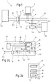
- FIG. 1 shows a monitoring system 1, the at least one, in the present case two monitoring devices 3.1, 3.2 and a monitoring center 5 includes. Both the surveillance center 5 as well as the two monitoring devices 3.1, 3.2 each have two input connections 7.1 and 7.2, each with mains voltage lines 9.1 or 9.2 electrical are connected.
- the mains voltage lines 9.1, 9.2 are part of a permanently installed power supply network, for example for an apartment or a house. The interface between this is fixed installed network and the one to be set up by the user The area is shown schematically in FIG marked a double line 11. Under one Interface 11 is, for example, an electrical outlet to understand.
- the two monitoring devices 3.1, 3.2 point in addition to the input connections 7.1, 7.2 also Output connections 13.1, 13.2, which are electrical with a household appliance 15.1 or 15.2 and connected there to the mains voltage inputs are.
- household appliances for example around washing machines, laundry dryers, Refrigerators or freezers etc.
- the construction of a monitoring device 3 should now be described in more detail with reference to FIG. 2a.
- the monitoring device 3 comprises two electrical lines 17.1, 17.2, the input connections 7.1, 7.2 with the output connections Connect 13.1 or 13.2.
- a switching element 19 coupled, the the electrical connection between input and output connections depending on a control signal can interrupt.
- This control signal is from a control device 21 generated, which in turn with the two Lines 17.1, 17.2 is electrically connected.
- the control device 21 is a storage device 23 assigned, the data exchange for example via a bus system 25. Furthermore the control device 21 is a detection device 25, whose input connections with the are connected to both lines 17.1 and 17.2. To transfer data between the Detection device 25 and the control device 21 lines 27 are provided.
- the control device 21 in turn comprises a Transmitting and receiving device 29 and an evaluation device 31.
- the transceiver 29 has a modulator / demodulator, not shown on that modulates data signals and couples into the lines 17.1, 17.2 and the over these lines transmit modulated data signals demodulated and fed to the evaluation device 31.
- the data signals it is also possible to use the data signals to transmit wirelessly, for example by radio.
- the evaluation device 31 is among others the detection device 25 connected to the detected and evaluate transmitted data, corresponding Generate data signals and send them to the Transmit / receive device 29 to transmit. About that In addition, the evaluation device 31 with the Storage device 23 connected via bus 25 in order depending on that of the detection device 25 delivered signals corresponding data from the Read memory.
- the control device 21 assigned a self-learning element 33, for example Activated by the user via a control element can be.
- This self-learning element will be described in detail later.
- the monitoring device 3 has one of the Interface assigned to control device 34, the connection of additional recording devices, for example a water meter, serves.
- additional recording devices for example a water meter
- the network parameters monitor additional parameters.
- control devices for example to operate a valve or to Control a flow rate.
- the monitoring center 5 shown in FIG. 1 comprises - as shown in Figure 2b - a control device 35 with a transmitting and receiving unit 37 connected to the ports 7.1 and 7.2 is.
- the control device 35 is a display unit 39 selected for displaying operating states Household appliances, as well as an input device 41, for example in the form of a keyboard Assigned data input.
- the function of the monitoring device 3 and the monitoring center 5 is now in the following described, being exemplary as a household appliance 15 a washing machine is to be monitored.
- a washing machine 15.1 runs through during a Washing programs different operating states, for example, taking in water, heating of water, drive the washing drum with different speeds, pumping the Water etc.
- Each of these operating states identifies through a defined energy intake out.
- the height of the flowing changes Electricity in every operating state. It also changes also the phase relationship between electricity and tension, depending on whether in the individual Operating conditions ohmic or inductive loads be supplied. Furthermore, arise during use of phase control circuits harmonics certain frequency. Based on these parameters you can make a statement about it in what operating condition the washing machine 15.1 is currently located. This assignment of voltage / current parameters makes to operating states take advantage of the present invention.
- the monitoring device 3.1 in the power supply lines of the washing machine 15.1 switched on. Becomes the monitoring device 3.1 in the form of an intermediate plug, is particularly easy to switch on. In the initial deactivated state of the Monitoring device 3.1 is the switching element 19 closed, so that an electrical connection between the input terminals 7 and the output terminals 13 exists. The washing machine 15.1 can then be operated as usual.
- the detection device 25 Voltage, current, frequency and impedance values the lines 17.1, 17.2. These values are over the lines 27 of the control device 21 and there supplied to the evaluation device 31.
- the evaluation device 31 then reads from the memory device 23 the information stored on these values about the operating status of the washing machine.
- the control device 31 controls the switching element 19, which thereupon the electrical Connection between the input connections 7 and interrupts the output terminals 13. At the same time will this faulty operating condition User via the display device 39 of the monitoring center 5 and acoustically if necessary an alarm circuit in the monitoring device 3 is displayed. Should the user continue to operate wish, he can use the keyboard 41 Control device 35 cause a modulated Generate data signal and lines 9.1, 9.2. This data signal is from the transceiver 29 of the control device 21 received and the evaluation device 31 fed. This then ensures that the Switching element 19 again in the closed state is switched so that continued operation is possible. Of course you can Switching element 19 also by means of a on the monitoring device 3.1 self-provided control element switch.
- the monitoring device 3 are only in the storage device 23 concerning a specific household appliance Data stored. For flexibility, however it is possible to increase the data of a variety filing of household appliances, for example the one to be monitored by means of DIP switches Household appliance before commissioning the monitoring device is selectable. Another The flexibility can then be increased if the data is in a so-called "learning mode" during operation of the household appliance to be monitored written into the memory device 23 will. In this mode, the self-learning element ensures 33 of the monitoring device 3 therefor that those detected by the detection device 25 Data during the operation of the household appliance 15 first transmitted to the monitoring center 5 and be displayed there. The user then has assign the respective operating status to this data, so that after transmission of this operating state date to the monitoring device 3 corresponding data pair in the storage device 23 can be registered.
- the monitoring device 3 a variety of different Functions assigned. Of course can be some of these functions also run from the monitoring center 5, so that the monitoring device 3 itself with less construction effort is realizable. That's the way it is for example, the evaluation device 31 and the storage device 23 in the monitoring center 5 to take.
- the monitoring device In this case, 3 only has the task to capture the network parameters and these recorded values as a modulated data signal to the Monitoring center 5 to transmit, where then Evaluation takes place.
- the monitoring system described above consisting from at least one monitoring device 3 and a monitoring center 5 thus opens one easy way not to have appropriate facilities disposing household appliances with a Equip monitoring function without having to Electronics of the devices themselves can be intervened ought to.
Abstract
Description
Die Erfindung betrifft eine Überwachungseinrichtung für netzbetriebene Haushaltsgeräte zur Kopplung mit Netzstromzuleitungen.The invention relates to a monitoring device for mains-operated household appliances for coupling with Mains power supply lines.
Moderne Haushaltsgeräte, wie beispielsweise Waschmaschinen, Wäschetrockner etc., verfügen heutzutage über aufwendige Elektronik, mit deren Hilfe unterschiedliche Betriebszustände erfaßt und abhängig davon die entsprechenden Funktionen ausgelöst werden. Hierzu zählt beispielsweise auch, das Haushaltsgerät abzuschalten, wenn ein fehlerhafter Betriebszustand erkannt wird. Eine derartige Möglichkeit, Betriebszustände zu überwachen, ist jedoch bei älteren Haushaltsgeräten aufgrund der fehlenden Elektronik nicht möglich.Modern household appliances, such as washing machines, Tumble dryers etc. have nowadays about elaborate electronics, with the help of which different Operating conditions recorded and dependent of which the corresponding functions are triggered. This also includes, for example, the household appliance switch off when a faulty operating condition is recognized. Such a way Monitoring operating conditions is, however in older household appliances due to the lack of Electronics not possible.
Die Aufgabe der vorliegenden Erfindung besteht deshalb darin, eine Überwachungseinrichtung zu schaffen, mit deren Hilfe sich auch Haushaltsgeräteüberwachen lassen, die nicht über entsprechend eingebaute Überwachungsschaltungen verfügen. The object of the present invention is therefore in creating a monitoring facility with the help of which household appliances are also monitored let that not have built in accordingly Monitoring circuits have.
Diese Aufgabe wird durch die Überwachungseinheit
mit den Merkmalen des Anspruchs 1 gelöst. Die Überwachungseinheit
umfaßt eine Erfassungsvorrichtung,
die den Netzzuleitungen zugeordnet ist und die
Netzparameter, beispielsweise Spannung, Strom, Frequenz
oder Impedanz, erfaßt, eine Speichervorrichtung,
in der bestimmte Betriebszustände des Haushaltsgeräts
mit den entsprechenden Netzparametern
abgelegt sind, sowie eine Auswerteeinrichtung, die
abhängig von den erfaßten Netzparametern den jeweiligen
Betriebszustand aus der Speichervorrichtung
ausliest. Dadurch ist es möglich, ältere Haushaltsgeräte
nachzurüsten, wobei die Überwachungseinrichtung
vorzugsweise in Form eines Zwischensteckers in
die Netzspannungsversorgung des Haushaltsgeräts
eingekoppelt wird. Ein Eingriff in die Elektronik
des Haushaltsgeräts ist somit nicht notwendig.This task is performed by the monitoring unit
solved with the features of
Vorzugsweise werden die Datensignale mittels eines Modulationselements moduliert und vorzugsweise in die Netzzuleitungen eingekoppelt oder alternativ drahtlos übertragen.The data signals are preferably transmitted using a Modulation element modulated and preferably in the mains supply lines coupled in or alternatively wirelessly transmitted.
Um bei einer Betriebsstörung das Haushaltsgerät abschalten zu können, umfaßt die Übervachungseinheit ein Schalterelement, das von der Auswerteeinrichtung steuerbar ist.To switch off the household appliance in the event of a malfunction to be able to include the monitoring unit a switch element by the evaluation device is controllable.
In einer weiteren Ausbildung der Erfindung weist die Auswerteeinrichtung ein Empfangselement zum Empfang von über die Netzzuleitungen übertragenen Datensignale auf. Damit ist es möglich, das Haushaltsgerät ferngesteuert ein- beziehungsweise auszuschalten. In a further embodiment of the invention the evaluation device a receiving element for Reception of data transmitted via the mains supply lines Data signals on. This makes it possible to use the household appliance switched on or off remotely.
In einer vorteilhaften Weiterbildung umfaßt die Auswerteeinrichtung ein Selbstlernelement, mit dessen Hilfe die momentan erfaßten Netzparameter zusammen mit dem beispielsweise manuell eingebbaren Betriebszustand in der Speichervorrichtung ablegbar sind. Damit läßt sich die Übervachungseinrichtung für unterschiedliche Haushaltsgeräte einsetzen.In an advantageous development, the Evaluation device a self-learning element, with its Help the network parameters currently recorded together with the example, which can be entered manually Operating state can be stored in the storage device are. This enables the monitoring device use for different household appliances.
Die Erfindung wird nun anhand eines Ausführungsbeispiels mit Bezug auf die Zeichnungen näher beschrieben. Dabei zeigen:
Figur 1- eine schematische Darstellung eines Überwachungssystems mit mehreren Überwachungseinrichtungen,
- Figur 2a
- ein Funktionsblockdiagramm einer Überwachungseinrichtung, und
- Figur 2b
- ein Fuktionsblockdiagramm einer Überwachungszentrale.
- Figure 1
- 1 shows a schematic representation of a monitoring system with several monitoring devices,
- Figure 2a
- a functional block diagram of a monitoring device, and
- Figure 2b
- a functional block diagram of a monitoring center.
In Figur 1 ist ein Überwachungssystem 1 gezeigt,
das zumindest eine, im vorliegenden Fall zwei Überwachungseinrichtungen
3.1, 3.2 sowie eine Übervachungszentrale
5 umfaßt. Sowohl die Überwachungszentrale
5 als auch die beiden Übervachungseinrichtungen
3.1, 3.2 weisen jeweils zwei Eingangsanschlüsse
7.1 und 7.2 auf, die jeweils mit Netzspannungsleitungen
9.1 beziehungsweise 9.2 elektrisch
verbunden sind. Die Netzspannungsleitungen 9.1, 9.2
sind Teil eines fest installierten Spannungsversorgungsnetzes,
beispielsweise für eine Wohnung oder
ein Haus. Die Schnittstelle zwischen diesem fest
installierten Netz und dem vom Benutzer einzurichtenden
Bereich ist in Figur 1 schematisch durch
eine Doppellinie 11 gekennzeichnet. Unter einer
Schnittstelle 11 ist beispielsweise eine Steckdose
zu verstehen.1 shows a
Die beiden Übervachungseinrichtungen 3.1, 3.2 weisen neben den Eingangsanschlüssen 7.1, 7.2 auch Ausgangsanschlüsse 13.1, 13.2 auf, die elektrisch mit einem Haushaltsgerät 15.1 beziehungsweise 15.2 und dort mit den Netzspannungseingängen verbunden sind. Bei den Haushaltsgeräten kann es sich beispielsweise um Waschmaschinen, Wäschetrockener, Kühl- oder Gefrierschränke etc., handeln.The two monitoring devices 3.1, 3.2 point in addition to the input connections 7.1, 7.2 also Output connections 13.1, 13.2, which are electrical with a household appliance 15.1 or 15.2 and connected there to the mains voltage inputs are. With household appliances, for example around washing machines, laundry dryers, Refrigerators or freezers etc.
Der Aufbau einer Überwachungseinrichtung 3 soll nun
mit Bezug auf die Figur 2a näher beschrieben werden.
Die Überwachungseinrichtung 3 umfaßt zwei
elektrische Leitungen 17.1, 17.2, die die Eingangsanschlüsse
7.1, 7.2 mit den Ausgangsanschlüssen
13.1 beziehungsweise 13.2 verbinden. In diesen Leitungsweg
ist ein Schaltelement 19 eingekoppelt, das
die elektrische Verbindung zwischen Ein- und Ausgangsanschlüssen
abhängig von einem Steuersignal
unterbrechen kann.The construction of a
Dieses Steuersignal wird von einer Steuereinrichtung
21 generiert, die ihrerseits mit den beiden
Leitungen 17.1, 17.2 elektrisch verbunden ist.This control signal is from a
Der Steuereinrichtung 21 ist eine Speichereinrichtung
23 zugeordnet, wobei der Datenaustausch beispielsweise
über ein Bussystem 25 erfolgt. Desweiteren
ist der Steuereinrichtung 21 eine Erfassungseinrichtung
25, deren Eingangsanschlüsse mit den
beiden Leitungen 17.1 und 17.2 verbunden sind, zugeordnet.
Zur Übermittlung von Daten zwischen der
Erfassungseinrichtung 25 und der Steuereinrichtung
21 sind Leitungen 27 vorgesehen.The
Die Steuereinrichtung 21 ihrerseits umfaßt eine
Sende- und Empfangseinrichtung 29 sowie eine Auswerteeinrichtung
31. Die Sende-/Empfangseinrichtung
29 weist einen -nicht dargestellten- Modulator/Demodulator
auf, der Datensignale moduliert und
in die Leitungen 17.1, 17.2 einkoppelt und der über
diese Leitungen übertragene modulierte Datensignale
demoduliert und der Auswerteeinrichtung 31 zuführt.
Selbstverständlich ist es auch möglich, die Datensignale
drahtlos, beispielsweise per Funk, zu übertragen.The
Die Auswerteeinrichtung 31 ist unter anderem mit
der Erfassungseinrichtung 25 verbunden, um die erfaßten
und übermittelten Daten auszuwerten, entsprechende
Datensignale zu generieren und an die
Sende-/Empfangseinrichtung 29 zu übertragen. Darüber
hinaus ist die Auswerteeinrichtung 31 mit der
Speichereinrichtung 23 über den Bus 25 verbunden,
um abhängig von den von der Erfassungseinrichtung
25 gelieferten Signalen entsprechende Daten aus dem
Speicher zu lesen.The
In einer vorteilhaften Ausgestaltung der Übervachungseinrichtung
3 ist der Steuereinrichtung 21
ein Selbstlernelement 33 zugeordnet, das beispielsweise
über ein Bedienelement vom Benutzer aktiviert
werden kann. Die Funktion dieses Selbstlernelements
wird später noch ausführlich beschrieben. In an advantageous embodiment of the
In einer weiteren vorteilhaften Ausführungsform
weist die Überwachungseinrichtung 3 eine der
Steuereinrichtung zugeordnete Schnittstelle 34 auf,
die dem Anschluß zusätzlicher Erfassungseinrichtungen,
beispielsweise eines Wassermengenmeßgerätes,
dient. Somit lassen sich neben den Netzparametern
zusätzliche Parameter überwachen. Des weiteren lassen
sich an die Schnittstelle 34 auch Schaltund/oder
Steuereinrichtungen anschließen, die beispielsweise
zum Betätigen eines Ventils oder zur
Steuerung einer Durchflußmenge dienen.In a further advantageous embodiment
the
Die in Figur 1 dargestellte Überwachungszentrale 5
umfaßt -wie in Figur 2b dargestellt- eine Steuereinrichtung
35 mit einer Sende- und Empfangseinheit
37, die mit den Anschlüssen 7.1 und 7.2 verbunden
ist. Der Steuereinrichtung 35 ist eine Anzeigeeinheit
39 zur Anzeige von Betriebszuständen ausgewählter
Haushaltsgeräte, sowie eine Eingabeeinrichtung
41, beispielsweise in Form einer Tastatur, zur
Eingabe von Daten zugeordnet.The
Die Funktion der Überwachungseinrichtung 3 sowie
der Überwachungszentrale 5 wird nun im folgenden
beschrieben, wobei als Haushaltsgerät 15 beispielhaft
eine Waschmaschine überwacht werden soll.The function of the
Eine Waschmaschine 15.1 durchläuft während eines Waschprogramms unterschiedliche Betriebszustände, so beispielsweise das Einlassen von Wasser, das Erhitzen des Wassers, Antrieb der Waschtrommel mit unterschiedlichen Geschwindigkeiten, Abpumpen des Wassers etc. Jeder dieser Betriebszustände kennzeichnet sich durch eine definierte Energieaufnahme aus. Mithin ändert sich die Höhe des fließenden Stroms in jedem Betriebszustand. Darüber hinaus ändert sich auch die Phasenbeziehung zwischen Strom und Spannung, abhängig davon, ob in den einzelnen Betriebszuständen ohmsche oder induktive Lasten versorgt werden. Desweiteren entstehen bei der Verwendung von Phasenanschnittschaltungen Oberwellen bestimmter Frequenz. Auf der Basis dieser Parameter läßt sich also eine Aussage darüber treffen, in welchem Betriebszustand sich die Waschmaschine 15.1 gerade befindet. Diese Zuordnung von Spannungs-/Stromparametern zu Betriebszuständen macht sich die vorliegende Erfindung zunutze.A washing machine 15.1 runs through during a Washing programs different operating states, for example, taking in water, heating of water, drive the washing drum with different speeds, pumping the Water etc. Each of these operating states identifies through a defined energy intake out. The height of the flowing changes Electricity in every operating state. It also changes also the phase relationship between electricity and tension, depending on whether in the individual Operating conditions ohmic or inductive loads be supplied. Furthermore, arise during use of phase control circuits harmonics certain frequency. Based on these parameters you can make a statement about it in what operating condition the washing machine 15.1 is currently located. This assignment of voltage / current parameters makes to operating states take advantage of the present invention.
Zunächst wird die Überwachungseinrichtung 3.1 in
die Spannungsversorgungsleitungen der Waschmaschine
15.1 eingeschaltet. Wird die Überwachungseinrichtung
3.1 in Form eines Zwischensteckers ausgebildet,
ist das Einschalten besonders einfach durchzuführen.
Im anfänglichen deaktivierten Zustand der
Überwachungseinrichtung 3.1 ist das Schaltelement
19 geschlossen, so daß eine elektrische Verbindung
zwischen den Eingangsanschlüssen 7 und den Ausgangsanschlüssen
13 besteht. Die Waschmaschine 15.1
läßt sich dann wie gewohnt betreiben.First, the monitoring device 3.1 in
the power supply lines of the washing machine
15.1 switched on. Becomes the monitoring device
3.1 in the form of an intermediate plug,
is particularly easy to switch on.
In the initial deactivated state of the
Monitoring device 3.1 is the switching
Sobald die Überwachungseinrichtung 3 -entweder direkt
oder indirekt über die Überwachungszentrale 5-aktiviert
wird, erfaßt die Erfassungseinrichtung 25
Spannungs-, Strom-, Freguenz- und Impedanz-Werte
der Leitungen 17.1, 17.2. Diese Werte werden über
die Leitungen 27 der Steuereinrichtung 21 und dort
der Auswerteeinrichtung 31 zugeführt. Die Auswerteeinrichtung
31 liest dann aus der Speichereinrichtung
23 die zu diesen Werten abgelegte Information
über den Betriebszustand der Waschmaschine aus.As soon as the monitoring device 3 - either directly
or 5-activated indirectly via the monitoring center
is detected, the
Diese Betriebszustandsdaten werden an die Sende-/Empfangseinrichtung
29 übermittelt, die die Daten
moduliert und in die Leitungen 17.1 und 17.2 einkoppelt.
Aufgrund der elektrischen Verbindung zwischen
den Leitungen 17.1, 17.2 und den Netzleitungen
9.1, 9.2 ist das modulierte Signal an jeder mit
diesen Leitungen 9.1, 9.2 verbundenen Schnittstellen
11 abgreifbar. Somit empfängt die Sende- und
Empfangseinheit 37 der ebenfalls an eine Schnittstelle
11 angeschlossenen Überwachungszentrale 5
dieses modulierte Signal, das dann entsprechend demoduliert
und von der Steuereinrichtung 35 verarbeitet
und als für den Benutzer lesbare Information
mittels der Anzeigeeinheit 39 angezeigt wirdThese operating status data are sent to the
Sollten die von der Erfassungseinrichtung 25 gelieferten
Signale auf einen fehlerhaften Betriebszustand
hinweisen, steuert die Steuereinrichtung 31
das Schaltelement 19 an, das daraufhin die elektrische
Verbindung zwischen den Eingangsanschlüssen 7
und den Ausgangsanschlüssen 13 unterbricht. Gleichzeitig
wird dieser fehlerhafte Betriebszustand dem
Benutzer über die Anzeigeeinrichtung 39 der Überwachungszentrale
5 und bei Bedarf akustisch mittels
einer Alarmschaltung in der Überwachungseinrichtung
3 angezeigt. Sollte der Benutzer einen Weiterbetrieb
wünschen, kann er über die Tastatur 41 die
Steuereinrichtung 35 dazu veranlassen, ein moduliertes
Datensignal zu generieren und den Leitungen
9.1, 9.2 aufzuprägen. Dieses Datensignal wird von
der Sende-/Empfangseinrichtung 29 der Steuereinrichtung
21 empfangen und der Auswerteeinrichtung
31 zugeführt. Diese sorgt dann dafür, daß das
Schaltelement 19 wieder in den geschlossenen Zustand
geschaltet wird, so daß ein Weiterbetrieb
möglich ist. Selbstverständlich läßt sich das
Schaltelement 19 auch mittels eines an der Überwachungseinrichtung
3.1 selbst vorgesehenen Bedienelements
umschalten.Should those supplied by the
In der einfachsten Ausführung der Überwachungseinrichtung
3 sind in der Speichereinrichtung 23 lediglich
die ein spezifisches Haushaltsgerät betreffenden
Daten abgelegt. Um die Flexibilität jedoch
zu erhöhen, ist es möglich, die Daten einer Vielzahl
von Haushaltsgeräten abzulegen, wobei beispielsweise
mittels DIP-Schaltern das zu überwachende
Haushaltsgerät vor Inbetriebnahme der Überwachungseinrichtung
auswählbar ist. Eine weitere
Erhöhung der Flexibilität läßt sich dann erreichen,
wenn die Daten in einem sogenannten "Lernmodus"
während eines Betriebs des zu überwachenden Haushaltsgeräts
in die Speichereinrichtung 23 eingeschrieben
werden. In diesem Modus sorgt das Selbstlernelement
33 der Überwachungseinrichtung 3 dafür,
daß die von der Erfassungseinrichtung 25 erfaßten
Daten während des Betriebs des Haushaltsgeräts 15
zunächst an die Überwachungszentrale 5 übertragen
und dort angezeigt werden. Der Benutzer hat dann
diesen Daten den jeweiligen Betriebszustand zuzuordnen,
so daß nach Übertragung dieses Betriebszustandsdatums
an die Überwachungseinrichtung 3 das
entsprechende Datenpaar in die Speichereinrichtung
23 eingeschrieben werden kann. In the simplest version of the
In dem zuvor beschriebenen Ausführungsbeispiel sind
der Überwachungseinrichtung 3 eine Vielzahl von unterschiedlichen
Funktionen zugeordnet. Selbstverständlich
lassen sich einzelne dieser Funktionen
auch von der Überwachungszentrale 5 ausführen, so
daß die Überwachungseinrichtung 3 selbst mit geringerem
baulichem Aufwand realisierbar ist. So ist es
beispielsweise denkbar, die Auswerteeinrichtung 31
sowie die Speichereinrichtung 23 in die Überwachungszentrale
5 zu nehmen. Der Überwachungseinrichtung
3 kommt in diesem Fall nur noch die Aufgabe
zu, die Netzparameter zu erfassen und diese
erfaßten Werte als moduliertes Datensignal an die
Überwachungszentrale 5 zu übertragen, wo dann die
Auswertung stattfindet.In the previously described embodiment
the monitoring device 3 a variety of different
Functions assigned. Of course
can be some of these functions
also run from the
Das zuvor beschriebene Überwachungssystem, bestehend
aus zumindest einer Überwachungseinrichtung 3
und einer Überwachungszentrale 5 eröffnet also eine
einfache Möglichkeit, nicht über entsprechende Einrichtungen
verfügende Haushaltsgeräte mit einer
Überwachungsfunktion auszustatten, ohne daß in die
Elektronik der Geräte selbst eingegriffen werden
müßte.The monitoring system described above, consisting
from at least one
Claims (8)
Applications Claiming Priority (2)
| Application Number | Priority Date | Filing Date | Title |
|---|---|---|---|
| DE19704216A DE19704216A1 (en) | 1997-02-05 | 1997-02-05 | Monitoring device for mains-operated household appliances |
| DE19704216 | 1997-02-05 |
Publications (3)
| Publication Number | Publication Date |
|---|---|
| EP0858143A2 true EP0858143A2 (en) | 1998-08-12 |
| EP0858143A3 EP0858143A3 (en) | 1999-10-06 |
| EP0858143B1 EP0858143B1 (en) | 2004-09-22 |
Family
ID=7819305
Family Applications (1)
| Application Number | Title | Priority Date | Filing Date |
|---|---|---|---|
| EP97121885A Expired - Lifetime EP0858143B1 (en) | 1997-02-05 | 1997-12-12 | Monitoring device for mains-operated houshold devices |
Country Status (3)
| Country | Link |
|---|---|
| EP (1) | EP0858143B1 (en) |
| AT (1) | ATE277387T1 (en) |
| DE (2) | DE19704216A1 (en) |
Cited By (10)
| Publication number | Priority date | Publication date | Assignee | Title |
|---|---|---|---|---|
| EP1039359A2 (en) * | 1999-03-25 | 2000-09-27 | ABBPATENT GmbH | Monitoring apparatus for electric consumers |
| WO2001015300A1 (en) | 1999-08-20 | 2001-03-01 | Wrap S.P.A. | Device, system and method for monitoring a household electric appliance |
| EP1164678A2 (en) * | 2000-06-13 | 2001-12-19 | Bticino S.P.A. | A system for the automatic closure of a switch |
| EP1283291A1 (en) * | 2001-08-07 | 2003-02-12 | Frank Eilers | Device for wireless transmission of information of the completion of the washing cycle and /or the drying cycle |
| EP1338935A1 (en) * | 2002-02-26 | 2003-08-27 | BSH Bosch und Siemens Hausgeräte GmbH | Interface device for a household appliance and household appliance |
| DE102005019377A1 (en) * | 2005-04-26 | 2006-11-09 | Siemens Ag | Method and device for remote monitoring |
| ITAT20090011A1 (en) * | 2009-07-30 | 2011-01-31 | Paser Srl | ELECTRONIC UNIT "P3 - PLUG & PLAY POWER", POWER SUPPLY ELEMENT / ELECTRIC MEDIATION FOR HOME AUTOMATION SYSTEMS. |
| DE102013220403A1 (en) * | 2013-10-10 | 2015-04-30 | Robert Bosch Gmbh | Device and method for state detection |
| EP2511720A3 (en) * | 2011-03-03 | 2017-07-12 | Samsung Electronics Co., Ltd. | Fault detection device and method for electrical appliance |
| DE102016108506B3 (en) * | 2016-05-09 | 2017-09-21 | Kriwan Industrie-Elektronik Gmbh | Method for protecting a non-driving, powered by an electric motor working machine and non-driving, driven by an electric motor work machine |
Families Citing this family (7)
| Publication number | Priority date | Publication date | Assignee | Title |
|---|---|---|---|---|
| DE19935003C2 (en) * | 1999-07-26 | 2003-02-27 | Osram Opto Semiconductors Gmbh | Power supply line network for information transmission |
| DE202006013311U1 (en) * | 2006-08-30 | 2008-01-03 | Merten Gmbh & Co. Kg | Connection unit of a bus system |
| DE102008039450A1 (en) * | 2008-08-25 | 2010-03-04 | Kernkraftwerke Lippe-Ems Gmbh | Method for detecting operating condition of electrical appliance i.e. electrical heating device, and for disconnecting appliance in non-determined operating condition, involves disconnecting electrical appliance from supply voltage |
| DE102009046083A1 (en) * | 2009-10-28 | 2011-05-12 | BSH Bosch und Siemens Hausgeräte GmbH | Household appliance, in particular dishwasher |
| DE102010002877B4 (en) * | 2010-03-15 | 2017-11-23 | BSH Hausgeräte GmbH | Method for operating a household appliance and household appliance |
| US9482703B2 (en) * | 2013-03-28 | 2016-11-01 | Sony Corporation | Method, sensor and system for analyzing appliances in a power line network |
| DE102013224867A1 (en) * | 2013-12-04 | 2015-06-11 | Siemens Aktiengesellschaft | Electrical connection device and circuit arrangement and associated method |
Citations (10)
| Publication number | Priority date | Publication date | Assignee | Title |
|---|---|---|---|---|
| US4642637A (en) * | 1984-08-27 | 1987-02-10 | Zellweger Uster, Ltd. | Method for transmitting data via a line of an alternating current distribution network, and a transmitter for carrying out the method |
| US4656593A (en) * | 1985-05-20 | 1987-04-07 | Westinghouse Electric Corp. | Multi-function load controller for carrier load control subsystem |
| US4896277A (en) * | 1988-05-03 | 1990-01-23 | Thermo King Corporation | Method of mapping refrigerated containers in a power line carrier based monitoring system |
| US5089809A (en) * | 1990-12-07 | 1992-02-18 | Carmichael Jr Raymond T | Remote indication of appliance status |
| DE4122989A1 (en) * | 1991-07-11 | 1993-01-14 | Mikro Mess Vertriebsgesellscha | Monitoring arrangement for electrical load operating hours - contains current sensor connecting mains input and output connectors and contg. operating hours timer and event counter |
| US5233342A (en) * | 1990-06-01 | 1993-08-03 | Pioneer Electronic Corporation | Remote control system |
| DE4413467C1 (en) * | 1994-04-19 | 1995-09-28 | Siemens Ag | Method for low-energy polling of binary states over long lines |
| DE19537280A1 (en) * | 1995-10-06 | 1997-04-10 | Aeg Hausgeraete Gmbh | Refrigerator freezer with infrared transmission of status signals |
| WO1997031430A1 (en) * | 1996-02-21 | 1997-08-28 | Citycom S.P.A. | System for data transmission, remote sensing, remote controls, remote readings and the like, particularly suitable for the electric power distribution lines |
| EP0806829A1 (en) * | 1996-05-11 | 1997-11-12 | AEG Hausgeräte GmbH | Electric household appliance such as cooking range, oven, cooking plate or the like |
Family Cites Families (3)
| Publication number | Priority date | Publication date | Assignee | Title |
|---|---|---|---|---|
| DE4008023A1 (en) * | 1990-03-09 | 1991-09-12 | Krone Ag | METHOD FOR IN-HOUSE VOICE AND DATA COMMUNICATION VIA THE IN-HOUSE POWER SUPPLY NETWORK |
| DE9310675U1 (en) * | 1993-07-14 | 1993-09-02 | Yang Ming Tung | Electrical circuit breaker |
| DE4413513A1 (en) * | 1994-04-19 | 1995-10-26 | Sitronic Elektrotech Ausruest | Controlling and monitoring electrical loads using microprocessor |
-
1997
- 1997-02-05 DE DE19704216A patent/DE19704216A1/en not_active Withdrawn
- 1997-12-12 DE DE59711947T patent/DE59711947D1/en not_active Expired - Lifetime
- 1997-12-12 EP EP97121885A patent/EP0858143B1/en not_active Expired - Lifetime
- 1997-12-12 AT AT97121885T patent/ATE277387T1/en active
Patent Citations (10)
| Publication number | Priority date | Publication date | Assignee | Title |
|---|---|---|---|---|
| US4642637A (en) * | 1984-08-27 | 1987-02-10 | Zellweger Uster, Ltd. | Method for transmitting data via a line of an alternating current distribution network, and a transmitter for carrying out the method |
| US4656593A (en) * | 1985-05-20 | 1987-04-07 | Westinghouse Electric Corp. | Multi-function load controller for carrier load control subsystem |
| US4896277A (en) * | 1988-05-03 | 1990-01-23 | Thermo King Corporation | Method of mapping refrigerated containers in a power line carrier based monitoring system |
| US5233342A (en) * | 1990-06-01 | 1993-08-03 | Pioneer Electronic Corporation | Remote control system |
| US5089809A (en) * | 1990-12-07 | 1992-02-18 | Carmichael Jr Raymond T | Remote indication of appliance status |
| DE4122989A1 (en) * | 1991-07-11 | 1993-01-14 | Mikro Mess Vertriebsgesellscha | Monitoring arrangement for electrical load operating hours - contains current sensor connecting mains input and output connectors and contg. operating hours timer and event counter |
| DE4413467C1 (en) * | 1994-04-19 | 1995-09-28 | Siemens Ag | Method for low-energy polling of binary states over long lines |
| DE19537280A1 (en) * | 1995-10-06 | 1997-04-10 | Aeg Hausgeraete Gmbh | Refrigerator freezer with infrared transmission of status signals |
| WO1997031430A1 (en) * | 1996-02-21 | 1997-08-28 | Citycom S.P.A. | System for data transmission, remote sensing, remote controls, remote readings and the like, particularly suitable for the electric power distribution lines |
| EP0806829A1 (en) * | 1996-05-11 | 1997-11-12 | AEG Hausgeräte GmbH | Electric household appliance such as cooking range, oven, cooking plate or the like |
Cited By (15)
| Publication number | Priority date | Publication date | Assignee | Title |
|---|---|---|---|---|
| DE19913471A1 (en) * | 1999-03-25 | 2000-09-28 | Abb Patent Gmbh | Monitoring device for electrical consumers |
| EP1039359A3 (en) * | 1999-03-25 | 2001-04-18 | ABBPATENT GmbH | Monitoring apparatus for electric consumers |
| EP1039359A2 (en) * | 1999-03-25 | 2000-09-27 | ABBPATENT GmbH | Monitoring apparatus for electric consumers |
| WO2001015300A1 (en) | 1999-08-20 | 2001-03-01 | Wrap S.P.A. | Device, system and method for monitoring a household electric appliance |
| EP1219004A1 (en) * | 1999-08-20 | 2002-07-03 | WRAP S.p.A. | Device, system and method for monitoring a household electrical appliance |
| EP1164678A3 (en) * | 2000-06-13 | 2006-01-18 | Bticino S.P.A. | A system for the automatic closure of a switch |
| EP1164678A2 (en) * | 2000-06-13 | 2001-12-19 | Bticino S.P.A. | A system for the automatic closure of a switch |
| EP1283291A1 (en) * | 2001-08-07 | 2003-02-12 | Frank Eilers | Device for wireless transmission of information of the completion of the washing cycle and /or the drying cycle |
| EP1338935A1 (en) * | 2002-02-26 | 2003-08-27 | BSH Bosch und Siemens Hausgeräte GmbH | Interface device for a household appliance and household appliance |
| DE102005019377A1 (en) * | 2005-04-26 | 2006-11-09 | Siemens Ag | Method and device for remote monitoring |
| ITAT20090011A1 (en) * | 2009-07-30 | 2011-01-31 | Paser Srl | ELECTRONIC UNIT "P3 - PLUG & PLAY POWER", POWER SUPPLY ELEMENT / ELECTRIC MEDIATION FOR HOME AUTOMATION SYSTEMS. |
| EP2511720A3 (en) * | 2011-03-03 | 2017-07-12 | Samsung Electronics Co., Ltd. | Fault detection device and method for electrical appliance |
| DE102013220403A1 (en) * | 2013-10-10 | 2015-04-30 | Robert Bosch Gmbh | Device and method for state detection |
| US10145867B2 (en) | 2013-10-10 | 2018-12-04 | Robert Bosch Gmbh | Device and method for detecting a state |
| DE102016108506B3 (en) * | 2016-05-09 | 2017-09-21 | Kriwan Industrie-Elektronik Gmbh | Method for protecting a non-driving, powered by an electric motor working machine and non-driving, driven by an electric motor work machine |
Also Published As
| Publication number | Publication date |
|---|---|
| EP0858143A3 (en) | 1999-10-06 |
| DE59711947D1 (en) | 2004-10-28 |
| ATE277387T1 (en) | 2004-10-15 |
| DE19704216A1 (en) | 1998-08-06 |
| EP0858143B1 (en) | 2004-09-22 |
Similar Documents
| Publication | Publication Date | Title |
|---|---|---|
| EP0858143B1 (en) | Monitoring device for mains-operated houshold devices | |
| EP0846991B1 (en) | Central control and monitoring apparatus for household appliances with wireless display unit | |
| DE69910397T2 (en) | SYSTEM AND METHOD FOR MONITORING SEVERAL ELECTRICAL USERS, IN PARTICULAR HOUSEHOLD APPLIANCES | |
| DE102005041455A1 (en) | Automated device e.g. field device and control device, has first program assigned to microcontroller for conversion of data bit stream and second program assigned to microcontroller for recognition of frequency-modulated line signal | |
| DE102010042717B4 (en) | Arrangement comprising a first and a second radio unit as well as a field device and a method for operating the same | |
| DE112005000122B4 (en) | Remote control system for household appliances and associated method | |
| EP3055705B1 (en) | Device and method for detecting a state | |
| DE3329049C2 (en) | ||
| EP2087318A1 (en) | System for determining and/or monitoring at least one process quantity | |
| EP1675274A1 (en) | Data transmission method over an AC power line | |
| DE102014018809A1 (en) | Transmission via a power grid with modulable consumer and electricity meter | |
| DE19943124A1 (en) | Device for detecting a power failure in a program-controlled household appliance | |
| EP2181907B1 (en) | Points diagnosis system | |
| EP2315338B1 (en) | (Stand-by) switching assembly for operating a household device and method for same | |
| AT410989B (en) | DEVICE FOR USE IN SALES AND / OR GASTRONOMY OPERATIONS | |
| CH705430B1 (en) | Building automation. | |
| EP2684204B1 (en) | Circuit breaker system for guidesystem for the electrical supply of a vehicle | |
| DE102017005625B4 (en) | Method of operating an electronic data collection device and data acquisition device | |
| DE10109156C2 (en) | Intelligent large household appliances | |
| EP1666809A1 (en) | Protection device for a hot water storage tank | |
| EP1670178A1 (en) | Remote monitoring of a device in a building | |
| EP3639379B1 (en) | Method and system for operating an electronic data-capturing device | |
| DE102022114902A1 (en) | System and method for recording, converting, analyzing and transferring consumption and performance data of a power-operated device | |
| DE202019003802U1 (en) | Retrofittable system for monitoring and transmission of status information and error conditions | |
| DE3012076A1 (en) | Methane detector for mine - distinguishes between faults and danger states by alternate antivalent circuit and line fault detector |
Legal Events
| Date | Code | Title | Description |
|---|---|---|---|
| PUAI | Public reference made under article 153(3) epc to a published international application that has entered the european phase |
Free format text: ORIGINAL CODE: 0009012 |
|
| AK | Designated contracting states |
Kind code of ref document: A2 Designated state(s): AT BE CH DE DK ES FI FR GB GR IE IT LI LU MC NL PT SE |
|
| RIC1 | Information provided on ipc code assigned before grant |
Free format text: 6G 07C 3/00 A, 6H 02J 13/00 B |
|
| PUAL | Search report despatched |
Free format text: ORIGINAL CODE: 0009013 |
|
| AK | Designated contracting states |
Kind code of ref document: A3 Designated state(s): AT BE CH DE DK ES FI FR GB GR IE IT LI LU MC NL PT SE |
|
| 17P | Request for examination filed |
Effective date: 20000406 |
|
| AKX | Designation fees paid |
Free format text: AT BE CH DE DK ES FI FR GB GR IE IT LI LU MC NL PT SE |
|
| 17Q | First examination report despatched |
Effective date: 20020701 |
|
| GRAP | Despatch of communication of intention to grant a patent |
Free format text: ORIGINAL CODE: EPIDOSNIGR1 |
|
| GRAS | Grant fee paid |
Free format text: ORIGINAL CODE: EPIDOSNIGR3 |
|
| GRAA | (expected) grant |
Free format text: ORIGINAL CODE: 0009210 |
|
| AK | Designated contracting states |
Kind code of ref document: B1 Designated state(s): AT BE CH DE DK ES FI FR GB GR IE IT LI LU MC NL PT SE |
|
| PG25 | Lapsed in a contracting state [announced via postgrant information from national office to epo] |
Ref country code: NL Free format text: LAPSE BECAUSE OF FAILURE TO SUBMIT A TRANSLATION OF THE DESCRIPTION OR TO PAY THE FEE WITHIN THE PRESCRIBED TIME-LIMIT Effective date: 20040922 Ref country code: IT Free format text: LAPSE BECAUSE OF FAILURE TO SUBMIT A TRANSLATION OF THE DESCRIPTION OR TO PAY THE FEE WITHIN THE PRE;WARNING: LAPSES OF ITALIAN PATENTS WITH EFFECTIVE DATE BEFORE 2007 MAY HAVE OCCURRED AT ANY TIME BEFORE 2007. THE CORRECT EFFECTIVE DATE MAY BE DIFFERENT FROM THE ONE RECORDED.SCRIBED TIME-LIMIT Effective date: 20040922 Ref country code: IE Free format text: LAPSE BECAUSE OF FAILURE TO SUBMIT A TRANSLATION OF THE DESCRIPTION OR TO PAY THE FEE WITHIN THE PRESCRIBED TIME-LIMIT Effective date: 20040922 Ref country code: FI Free format text: LAPSE BECAUSE OF FAILURE TO SUBMIT A TRANSLATION OF THE DESCRIPTION OR TO PAY THE FEE WITHIN THE PRESCRIBED TIME-LIMIT Effective date: 20040922 |
|
| REG | Reference to a national code |
Ref country code: GB Ref legal event code: FG4D Free format text: NOT ENGLISH |
|
| REG | Reference to a national code |
Ref country code: CH Ref legal event code: EP |
|
| REG | Reference to a national code |
Ref country code: IE Ref legal event code: FG4D Free format text: GERMAN |
|
| REF | Corresponds to: |
Ref document number: 59711947 Country of ref document: DE Date of ref document: 20041028 Kind code of ref document: P |
|
| PG25 | Lapsed in a contracting state [announced via postgrant information from national office to epo] |
Ref country code: LU Free format text: LAPSE BECAUSE OF NON-PAYMENT OF DUE FEES Effective date: 20041212 |
|
| REG | Reference to a national code |
Ref country code: CH Ref legal event code: NV Representative=s name: ISLER & PEDRAZZINI AG |
|
| PG25 | Lapsed in a contracting state [announced via postgrant information from national office to epo] |
Ref country code: SE Free format text: LAPSE BECAUSE OF FAILURE TO SUBMIT A TRANSLATION OF THE DESCRIPTION OR TO PAY THE FEE WITHIN THE PRESCRIBED TIME-LIMIT Effective date: 20041222 Ref country code: GR Free format text: LAPSE BECAUSE OF FAILURE TO SUBMIT A TRANSLATION OF THE DESCRIPTION OR TO PAY THE FEE WITHIN THE PRESCRIBED TIME-LIMIT Effective date: 20041222 Ref country code: DK Free format text: LAPSE BECAUSE OF FAILURE TO SUBMIT A TRANSLATION OF THE DESCRIPTION OR TO PAY THE FEE WITHIN THE PRESCRIBED TIME-LIMIT Effective date: 20041222 |
|
| PG25 | Lapsed in a contracting state [announced via postgrant information from national office to epo] |
Ref country code: MC Free format text: LAPSE BECAUSE OF NON-PAYMENT OF DUE FEES Effective date: 20041231 Ref country code: BE Free format text: LAPSE BECAUSE OF NON-PAYMENT OF DUE FEES Effective date: 20041231 |
|
| PG25 | Lapsed in a contracting state [announced via postgrant information from national office to epo] |
Ref country code: ES Free format text: LAPSE BECAUSE OF FAILURE TO SUBMIT A TRANSLATION OF THE DESCRIPTION OR TO PAY THE FEE WITHIN THE PRESCRIBED TIME-LIMIT Effective date: 20050102 |
|
| GBT | Gb: translation of ep patent filed (gb section 77(6)(a)/1977) |
Effective date: 20050115 |
|
| NLV1 | Nl: lapsed or annulled due to failure to fulfill the requirements of art. 29p and 29m of the patents act | ||
| REG | Reference to a national code |
Ref country code: IE Ref legal event code: FD4D |
|
| BERE | Be: lapsed |
Owner name: DEUTSCHE TELEKOM A.G. Effective date: 20041231 |
|
| PLBE | No opposition filed within time limit |
Free format text: ORIGINAL CODE: 0009261 |
|
| STAA | Information on the status of an ep patent application or granted ep patent |
Free format text: STATUS: NO OPPOSITION FILED WITHIN TIME LIMIT |
|
| ET | Fr: translation filed | ||
| 26N | No opposition filed |
Effective date: 20050623 |
|
| REG | Reference to a national code |
Ref country code: CH Ref legal event code: PCAR Free format text: ISLER & PEDRAZZINI AG;POSTFACH 1772;8027 ZUERICH (CH) |
|
| BERE | Be: lapsed |
Owner name: DEUTSCHE *TELEKOM A.G. Effective date: 20041231 |
|
| PG25 | Lapsed in a contracting state [announced via postgrant information from national office to epo] |
Ref country code: PT Free format text: LAPSE BECAUSE OF NON-PAYMENT OF DUE FEES Effective date: 20050222 |
|
| REG | Reference to a national code |
Ref country code: FR Ref legal event code: PLFP Year of fee payment: 19 |
|
| PGFP | Annual fee paid to national office [announced via postgrant information from national office to epo] |
Ref country code: CH Payment date: 20151222 Year of fee payment: 19 |
|
| PGFP | Annual fee paid to national office [announced via postgrant information from national office to epo] |
Ref country code: AT Payment date: 20151217 Year of fee payment: 19 |
|
| REG | Reference to a national code |
Ref country code: FR Ref legal event code: PLFP Year of fee payment: 20 |
|
| PGFP | Annual fee paid to national office [announced via postgrant information from national office to epo] |
Ref country code: GB Payment date: 20161222 Year of fee payment: 20 |
|
| PGFP | Annual fee paid to national office [announced via postgrant information from national office to epo] |
Ref country code: FR Payment date: 20161221 Year of fee payment: 20 |
|
| PGFP | Annual fee paid to national office [announced via postgrant information from national office to epo] |
Ref country code: DE Payment date: 20161220 Year of fee payment: 20 |
|
| REG | Reference to a national code |
Ref country code: CH Ref legal event code: PL |
|
| REG | Reference to a national code |
Ref country code: AT Ref legal event code: MM01 Ref document number: 277387 Country of ref document: AT Kind code of ref document: T Effective date: 20161212 |
|
| PG25 | Lapsed in a contracting state [announced via postgrant information from national office to epo] |
Ref country code: CH Free format text: LAPSE BECAUSE OF NON-PAYMENT OF DUE FEES Effective date: 20161231 Ref country code: LI Free format text: LAPSE BECAUSE OF NON-PAYMENT OF DUE FEES Effective date: 20161231 Ref country code: AT Free format text: LAPSE BECAUSE OF NON-PAYMENT OF DUE FEES Effective date: 20161212 |
|
| REG | Reference to a national code |
Ref country code: DE Ref legal event code: R071 Ref document number: 59711947 Country of ref document: DE |
|
| REG | Reference to a national code |
Ref country code: GB Ref legal event code: PE20 Expiry date: 20171211 |
|
| PG25 | Lapsed in a contracting state [announced via postgrant information from national office to epo] |
Ref country code: GB Free format text: LAPSE BECAUSE OF EXPIRATION OF PROTECTION Effective date: 20171211 |