EP0862349A2 - Switching device - Google Patents
Switching device Download PDFInfo
- Publication number
- EP0862349A2 EP0862349A2 EP98200159A EP98200159A EP0862349A2 EP 0862349 A2 EP0862349 A2 EP 0862349A2 EP 98200159 A EP98200159 A EP 98200159A EP 98200159 A EP98200159 A EP 98200159A EP 0862349 A2 EP0862349 A2 EP 0862349A2
- Authority
- EP
- European Patent Office
- Prior art keywords
- central memory
- cell
- atm
- deleted
- comparator
- Prior art date
- Legal status (The legal status is an assumption and is not a legal conclusion. Google has not performed a legal analysis and makes no representation as to the accuracy of the status listed.)
- Withdrawn
Links
Images


Classifications
-
- H—ELECTRICITY
- H04—ELECTRIC COMMUNICATION TECHNIQUE
- H04L—TRANSMISSION OF DIGITAL INFORMATION, e.g. TELEGRAPHIC COMMUNICATION
- H04L49/00—Packet switching elements
- H04L49/10—Packet switching elements characterised by the switching fabric construction
- H04L49/103—Packet switching elements characterised by the switching fabric construction using a shared central buffer; using a shared memory
-
- H—ELECTRICITY
- H04—ELECTRIC COMMUNICATION TECHNIQUE
- H04L—TRANSMISSION OF DIGITAL INFORMATION, e.g. TELEGRAPHIC COMMUNICATION
- H04L49/00—Packet switching elements
- H04L49/10—Packet switching elements characterised by the switching fabric construction
- H04L49/104—Asynchronous transfer mode [ATM] switching fabrics
- H04L49/105—ATM switching elements
- H04L49/108—ATM switching elements using shared central buffer
-
- H—ELECTRICITY
- H04—ELECTRIC COMMUNICATION TECHNIQUE
- H04L—TRANSMISSION OF DIGITAL INFORMATION, e.g. TELEGRAPHIC COMMUNICATION
- H04L49/00—Packet switching elements
- H04L49/50—Overload detection or protection within a single switching element
-
- H—ELECTRICITY
- H04—ELECTRIC COMMUNICATION TECHNIQUE
- H04L—TRANSMISSION OF DIGITAL INFORMATION, e.g. TELEGRAPHIC COMMUNICATION
- H04L12/00—Data switching networks
- H04L12/54—Store-and-forward switching systems
- H04L12/56—Packet switching systems
- H04L12/5601—Transfer mode dependent, e.g. ATM
- H04L2012/5638—Services, e.g. multimedia, GOS, QOS
- H04L2012/5646—Cell characteristics, e.g. loss, delay, jitter, sequence integrity
- H04L2012/5647—Cell loss
-
- H—ELECTRICITY
- H04—ELECTRIC COMMUNICATION TECHNIQUE
- H04L—TRANSMISSION OF DIGITAL INFORMATION, e.g. TELEGRAPHIC COMMUNICATION
- H04L12/00—Data switching networks
- H04L12/54—Store-and-forward switching systems
- H04L12/56—Packet switching systems
- H04L12/5601—Transfer mode dependent, e.g. ATM
- H04L2012/5638—Services, e.g. multimedia, GOS, QOS
- H04L2012/5646—Cell characteristics, e.g. loss, delay, jitter, sequence integrity
- H04L2012/5651—Priority, marking, classes
-
- H—ELECTRICITY
- H04—ELECTRIC COMMUNICATION TECHNIQUE
- H04L—TRANSMISSION OF DIGITAL INFORMATION, e.g. TELEGRAPHIC COMMUNICATION
- H04L12/00—Data switching networks
- H04L12/54—Store-and-forward switching systems
- H04L12/56—Packet switching systems
- H04L12/5601—Transfer mode dependent, e.g. ATM
- H04L2012/5638—Services, e.g. multimedia, GOS, QOS
- H04L2012/5646—Cell characteristics, e.g. loss, delay, jitter, sequence integrity
- H04L2012/5652—Cell construction, e.g. including header, packetisation, depacketisation, assembly, reassembly
- H04L2012/5653—Cell construction, e.g. including header, packetisation, depacketisation, assembly, reassembly using the ATM adaptation layer [AAL]
- H04L2012/5657—Cell construction, e.g. including header, packetisation, depacketisation, assembly, reassembly using the ATM adaptation layer [AAL] using the AAL3/4
-
- H—ELECTRICITY
- H04—ELECTRIC COMMUNICATION TECHNIQUE
- H04L—TRANSMISSION OF DIGITAL INFORMATION, e.g. TELEGRAPHIC COMMUNICATION
- H04L12/00—Data switching networks
- H04L12/54—Store-and-forward switching systems
- H04L12/56—Packet switching systems
- H04L12/5601—Transfer mode dependent, e.g. ATM
- H04L2012/5638—Services, e.g. multimedia, GOS, QOS
- H04L2012/5646—Cell characteristics, e.g. loss, delay, jitter, sequence integrity
- H04L2012/5652—Cell construction, e.g. including header, packetisation, depacketisation, assembly, reassembly
- H04L2012/5653—Cell construction, e.g. including header, packetisation, depacketisation, assembly, reassembly using the ATM adaptation layer [AAL]
- H04L2012/5658—Cell construction, e.g. including header, packetisation, depacketisation, assembly, reassembly using the ATM adaptation layer [AAL] using the AAL5
-
- H—ELECTRICITY
- H04—ELECTRIC COMMUNICATION TECHNIQUE
- H04L—TRANSMISSION OF DIGITAL INFORMATION, e.g. TELEGRAPHIC COMMUNICATION
- H04L12/00—Data switching networks
- H04L12/54—Store-and-forward switching systems
- H04L12/56—Packet switching systems
- H04L12/5601—Transfer mode dependent, e.g. ATM
- H04L2012/5678—Traffic aspects, e.g. arbitration, load balancing, smoothing, buffer management
- H04L2012/5681—Buffer or queue management
- H04L2012/5682—Threshold; Watermark
-
- H—ELECTRICITY
- H04—ELECTRIC COMMUNICATION TECHNIQUE
- H04L—TRANSMISSION OF DIGITAL INFORMATION, e.g. TELEGRAPHIC COMMUNICATION
- H04L49/00—Packet switching elements
- H04L49/20—Support for services
Definitions
- the invention relates to a coupling device (switch) for a local after asynchronous transfer mode (ATM) working local network, which one Central storage (CCM) for the temporary storage of on feeder lines incoming packets (frames) formed from individual ATM cells, one Central memory control device for controlling the storage in the central memory (CCM) and the reading and reading process of the packages in and out the central memory (CCM) and one from the central memory control device
- Controlled demultiplexer for forwarding the packets (frames) to customer lines contains, in addition, counting means for counting in the central memory (CCM) incoming ATM cells and extinguishing agents for packets Deletion of ATM cells to prevent central memory overflow (CCM) are provided.
- ATM asynchronous transfer mode
- a virtual path in turn represents a group of virtual channels (VC).
- VCI virtual channel identifier
- VPI virtual path identifier
- an ATM connection is established via a physical line, it is this ATM connection the full transmission rate of the physical line Available. Because there is no mapping between transfer rates within physical lines and the individual ATM connections takes place, the Traffic of an ATM connection can be set with certain parameters. This definition is necessary to avoid overload situations in the network avoid and on the other hand to a certain quality of ATM connections guarantee.
- a traffic contract between a ATM application and the network regarding the desired ATM connection getting closed.
- the ATM network decides whether to accept a new one Connection based on the given traffic parameters so that the transportation contract only comes about with the acceptance of an ATM connection.
- the ATM network guarantees compliance with those requested by the ATM application Quality of service of the connection if this application is in the transport contract negotiated values of traffic parameters.
- To monitor the Traffic parameters are used by the UPC function (user-parameter-control).
- ATM adaptation layers AAL (ATM adaptation layer) defined.
- AAL ATM adaptation layer
- the image of the User data i.e. larger data packets or synchronous bit streams, on each 53 byte sized ATM cells realized.
- This variant realizes a synchronous bit stream and is used to adapt synchronous voice or video channels, but not for the packet-oriented Data communication used.
- This type of service supports both connectionless and also connection-oriented LAN communication in ATM networks.
- AAL 5 can handle up to 48 bytes instead of 44 with AAL 3/4, can be transported as a payload per ATM cell, which means that Share of administrative information drops.
- the information can be transmitted with approximately 1300 ATM cells using AAL 5, the so-called EOM (end of message) bit for identifying the end of information being stored in the header of the last cell.
- EOM end of message
- a system of the type mentioned is known from "Dynamics of TCP Traffic over ATM Networks ", Romanow, Floyd et, IEEE-JSAC, vol. 13, No. 4, May 1995, Pages 633-644.
- This system refers to TCP (transmission control protocol) Connections in ATM networks, the task of which is an overflow to avoid (congestion) the central memory in the coupling device.
- This The system assumes an overflow control for the central store after so-called frame discard process.
- the incoming frames in the Central memory connection-oriented (VC-oriented) temporarily stored and for the case that an overflow occurs at the output of the coupling device, the entire Frame belonging to a specific VC deleted.
- the so-called "resource management Application” determines the fill level of the buffer used and determines which one Package is to be deleted. The resulting effect on the fill level continues observed and possibly further packages deleted. As long as the level is still the deletion process of Packets from different connections continued.
- This known method is suitable for storage with very large storage capacity, for example for Capacities of more than 10,000 cells.
- a disadvantage of this system is however, in that due to the VC-oriented division of the memory Organizer designed specifically for this division is required. Since the Adjustment process with regard to the fill level of the memory always some Lasts milliseconds, there is an inertia effect that prevents the application of the "early packet drop "method unsuitable for small (decentrally organized) cell buffers makes.
- the invention has for its object a system of the type mentioned to develop further in such a way that for central storage with small sizes, below 1000 cells.
- the central memory control device has at least one comparator device arranged upstream of the central memory, which cooperates with the counting means and control logic in such a way that when a predeterminable threshold value (L disc ) for the filling level of the central memory (CCM) is reached, a predeterminable number of Connections (VC) are defined on the basis of the order of arrival of the ATM cells assigned to the respective connection (VC), and that each ATM cell of the packet belonging to the defined VC value is deleted before it arrives in the central memory.
- a predeterminable threshold value L disc
- VC predeterminable number of Connections
- the invention is characterized in that, depending on the filling state of the Memory by the number of stored ATM cells by means of a counter the first incoming cell and each subsequent cell is determined every incoming package that is assigned to a specific VC, is deleted. This means that measures will be taken depending on Establish the connection as many received cells as possible so that only one small number of incoming packets is deleted.
- the invention Solution enables the coupling device itself to delete the packets specifies. For this purpose, certain connections are made from the total cell current Filtered priority criteria and deleted. The result is a similar one Behavior as in the frame discard process, in particular the early packet drop process, however, applicability down to very small cell sizes (on-chip buffer) of, for example, only 128 cells, in which it is particularly optimal Storage management arrives.
- the central memory management system proposed according to the invention takes into account the fact that "malicious" users can occur that can lead to an overload of the coupling device, by violating their traffic contract.
- Packages of such users preferably tracked down and deleted according to the invention. Even with such users, who in principle comply with the traffic contract, it may from time to time Memory overloads are coming.
- the predefinable number of the defined Connections VC results from the fact that the VC values in the serial data stream each of the successive ATM cells of different VC values recorded and the different VC values are stored in a table.
- a Predeterminable number, for example seven, are the VC values of one to be deleted Cell defined, i.e. every time such a VC value is detected in the cell this cell is deleted and thus prevents further storage space for the associated frame is occupied.
- a preferred embodiment of the invention provides that the at least one Comparator is connected to a discard table that contains the connection identifiers (VC) of the frames to be deleted, the delete table containing the Extinguishing means for deleting each incoming ATM cell activated, its connection identifier (VC) is stored in the delete table.
- VC connection identifier
- the provision of such Deletion table can be suitably combined with the control logic, so that a simple structure is achieved and the delete table in this way by the Comparator and this associated counter is triggered.
- the central memory control device at least two comparators with different specifiable Has threshold values such that when the upper threshold value is exceeded a start of the deletion table and that when it falls below the lower threshold the deletion table is stopped. This results in the different threshold values a "switching hysteresis", whereby by the definition the width of which can further optimize memory management.
- the central memory control device readout means for Detection of cell loss priority information in the cell header and that a further threshold value for the filling level of the central store of another Comparator can be specified, which interacts with the control logic in such a way that above the further threshold value those ATM cells are deleted whose Cell loss priority is high, even at such a low memory level, where the deletion table described above is not yet activated, a Preselection for cells to be deleted can be made by using those cells a high loss priority can be deleted "as a precaution".
- the central memory control device identifying means for Detection of determination information in the cell header and that a third threshold value from another comparator for the fill level of the Central memory can be specified and that this with the determination detection means and the control logic cooperates such that above the third Threshold values are deleted from all ATM cells that are not for the central processing unit (CPU) are certain control cells.
- the preferred application is the described memory management strategy aimed at the matching layers AAL 3/4 or AAL 5.
- the system according to the invention is preferably used for very small systems Cell storage, for example with cell storage integrated on a chip a capacity of 128 ATM cells, where it is particularly optimized for Storage management arrives.
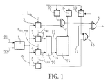
- Fig. 1 shows a section of a block diagram for an embodiment of the system according to the invention, which the memory organization (buffer management) of a cell memory for 128 ATM cells.
- This memory size is thus compared to the number of connections to be processed, e.g. 1024, very low.
- a central memory control device switch is shown in the ATM cell stream enters (cell arrived) or exits (cell emitted) or is deleted (cell discarded).
- the entrance of this central storage control device forms a counter 1 (counter), which is incremented (input 21) if one ATM cell enters the memory or which is decremented (input 22), when an ATM cell leaks or is deleted.
- the current counter reading is connected to four comparators 2 to 5, to which fixed threshold values L CLP , L disc , L disc-stop and L alfull can be specified. Downstream of the outputs of the comparators 2 to 5 is a control logic, by means of which it is decided whether a single cell is to be deleted (discard cell) or not.
- the input of the control logic is formed by a removal device, that of a readout means 20, a priority detection device 16 and one Cell determination information detection device 19 exists and by means of which the Cell header of the currently counted ATM cell information available is read out.
- the bit information CLP (cell loss priority) is converted from the header by the Readout means 20, the priority of the cell (prio) by the priority detection device 16 and the determination by the cell determination information acquisition means 19 read out.
- the cell determination information acquisition device 19 is given an identifier (port identifier) of a circuit part, not shown, which destination (port) the respective cell should be fed.
- the four comparators 2 to 5 are connected to the counter 1 via bus lines 6.
- the output of this first AND gate 7 reaches the input of an OR gate 8.
- the output of the second comparator 3 with the predeterminable threshold value L disc is connected to the set input 9 of a flip-flop 10.
- the output of the third comparator 4, to which the predeterminable threshold value L disc stop is applied, is connected to the reset input 11 of the flip-flop 10.
- the start and stop outputs 13 and 14 of flip-flop 10 are coupled to a discard table 15.
- the output 17 of the delete table 15 also forms an input of the OR gate 8.
- the output of the fourth comparator 5, which is coupled to the threshold value L alfull is connected to the input of a further AND gate 18.
- the other input of this further AND gate 18 is connected to the output of the cell determination information acquisition device 19 via an inverting input. This indicates whether a cell is intended for the central processing unit (CPU) or comes from it.
- the output of this further AND gate 18 forms the third input of the OR gate 8.
- L L disc , which is described as follows:
- the threshold values for the comparators 2 to 5 can be freely adapted to the desired strategy behavior.
- the threshold values L CLP and L disc can be interchanged.
- a state diagram for the deletion table 15 is used, according to which the deletion table 15 is written, read and evaluated:
- the initial state in the state diagram according to FIG. 3 is the "deactivate" state.
- the erase table receives the "start" command, whereby the "clear" state is first reached and then the erase table is filled.
- the deletion table (“fill-table")
- deletion table will decrease when the level drops accordingly reset by the stop output of the flip-flop, it gets back into the "deactivate" initial state back.
Abstract
Description
Die Erfindung betrifft eine Koppeleinrichtung (switch) für ein lokales nach dem asynchronen Transfermodus (ATM) arbeitendes lokales Netzwerk, welches einen Zentralspeicher (CCM) zur Zwischenspeicherung von auf Zubringerleitungen eintreffenden aus einzelnen ATM-Zellen gebildete Paketen (Frames), eine Zentralspeichersteuereinrichtung für die Steuerung der Speicherung im Zentralspeicher (CCM) und des Einlese- und Auslesevorganges der Pakete in den bzw. aus dem Zentralspeicher (CCM) und einen von der Zentralspeichersteuereinrichtung gesteuerten Demultiplexer zur Weiterleitung der Pakete (frames) auf Abnehmerleitungen enthält, wobei darüber hinaus Zählmittel zum Zählen der in den Zentralspeicher (CCM) eintretenden ATM-Zellen und Löschmittel zum paketweisen Löschen von ATM-Zellen zur Überlaufverhinderung des Zentralspeichers (CCM) vorgesehen sind.The invention relates to a coupling device (switch) for a local after asynchronous transfer mode (ATM) working local network, which one Central storage (CCM) for the temporary storage of on feeder lines incoming packets (frames) formed from individual ATM cells, one Central memory control device for controlling the storage in the central memory (CCM) and the reading and reading process of the packages in and out the central memory (CCM) and one from the central memory control device Controlled demultiplexer for forwarding the packets (frames) to customer lines contains, in addition, counting means for counting in the central memory (CCM) incoming ATM cells and extinguishing agents for packets Deletion of ATM cells to prevent central memory overflow (CCM) are provided.
In lokalen Netzwerken, welche nach dem Asynchronen-Transfer-Modus (ATM) arbeiten, werden aus den zu übertragenden Informationen (Nachrichten) Blöcke fester Länge gebildet. Jeder Block wird mit einer zusätzlichen Steuerinformation zu einer Übertragungseinheit ergänzt, die als ATM-Zelle bezeichnet wird. Jede ATM-Zelle setzt sich dabei zusammen aus einem Zellenkopf von 5 Byte Länge (header) und einem Informationsfeld von 48 Byte Länge (payload), in dem die zu übertragenden Informationen enthalten sind.In local networks that use the asynchronous transfer mode (ATM) work, the information (messages) to be transmitted blocks fixed length formed. Each block comes with additional control information a transmission unit added, which is referred to as an ATM cell. Every ATM cell is composed of a cell header of 5 bytes in length (header) and an information field of 48 bytes in length (payload) in which the to be transmitted Information is included.
Bei ATM-Netzen wird die verfügbare Übertragungskapazität (Bandbreite) eines Breitbandkanals für unterschiedliche Übermittlungsdienste, wie Datenübermittlungsdienste, Sprachübermittlungsdienste, Videodienste (z.B. Video-Konferenzen oder Video-Datenbanken) oder bei der Übermittlung von Multimedia-Informationen, bei denen Sprachen-, Daten- und Video-Informationen miteinander kombiniert sind, in sogenannte virtuelle Pfade (virtual path, VP) unterteilt. Ein virtueller Pfad repräsentiert wiederum eine Gruppe von virtuellen Kanälen (virtual channel, VC). Beim Aufbau einer virtuellen Verbindung zwischen einem Sender und einem Empfänger wird zunächst der geeignete virtuelle Pfad ausgewählt. Anschließend wird ein Teil der Bandbreite als virtueller Kanal dieses Pfades belegt. Für die Identifizierung des virtuellen Kanals wird die Kennung VCI (virtual channel identifier) verwendet, während für die Identifizierung der Pfade die Kennung VPI (virtual path identifier) verwendet wird. Die Angabe von VPI und VCI stellt somit die logische Kennung für eine einzelne Verbindung dar.With ATM networks, the available transmission capacity (bandwidth) becomes one Broadband channel for different transmission services, such as data transmission services, Voice transmission services, video services (e.g. video conferences or Video databases) or in the transmission of multimedia information where language, data and video information are combined, in so-called virtual paths (VP) divided. A virtual path in turn represents a group of virtual channels (VC). When establishing a virtual connection between a transmitter and a The appropriate virtual path is first selected for the recipient. Subsequently part of the bandwidth is used as a virtual channel of this path. For the The identifier VCI (virtual channel identifier), while the identifier VPI is used to identify the paths (virtual path identifier) is used. The indication of VPI and VCI is thus is the logical identifier for a single connection.
Wird eine ATM-Verbindung über eine physikalische Leitung realisiert, so steht dieser ATM-Verbindung die volle Übertragungsrate der physikalischen Leitung zur Verfügung. Da keine Zuordnung zwischen Übertragungsraten innerhalb von physikalischen Leitungen und den einzelnen ATM-Verbindungen stattfindet, muß der Verkehr einer ATM-Verbindung mit bestimmten Parametern festgelegt werden. Diese Festlegung ist notwendig, um einerseits Überlast-Situationen im Netz zu vermeiden und um andererseits eine bestimmte Güte von ATM-Verbindungen zu gewährleisten.If an ATM connection is established via a physical line, it is this ATM connection the full transmission rate of the physical line Available. Because there is no mapping between transfer rates within physical lines and the individual ATM connections takes place, the Traffic of an ATM connection can be set with certain parameters. This definition is necessary to avoid overload situations in the network avoid and on the other hand to a certain quality of ATM connections guarantee.
Um dies zu erreichen, muß ein Verkehrsvertrag (traffic contract) zwischen einer ATM-Anwendung und dem Netz hinsichtlich der gewünschten ATM-Verbindung geschlossen werden. Das ATM-Netz entscheidet über die Annahme einer neuen Verbindung aufgrund der vorgegebenen Verkehrsparameter, so daß der Verkehrsvertrag erst mit der Annahme einer ATM-Verbindung zustande kommt. Damit garantiert das ATM-Netz die Einhaltung der von der ATM-Anwendung angeforderten Dienstgüte der Verbindung, wenn diese Anwendung die im Verkehrsvertrag ausgehandelten Werte von Verkehrsparametern einhält. Zur Überwachung der Verkehrsparameter dient die UPC-Funktion (user-parameter-control). In order to achieve this, a traffic contract between a ATM application and the network regarding the desired ATM connection getting closed. The ATM network decides whether to accept a new one Connection based on the given traffic parameters so that the transportation contract only comes about with the acceptance of an ATM connection. In order to the ATM network guarantees compliance with those requested by the ATM application Quality of service of the connection if this application is in the transport contract negotiated values of traffic parameters. To monitor the Traffic parameters are used by the UPC function (user-parameter-control).
Je nach der unterstützten ATM-Anwendung werden bestimmte ATM-Anpassungsschichten AAL (ATM-adaption layer) definiert. Im AAL wird die Abbildung der Nutzdaten, also größerer Datenpakete oder synchroner Bit-Ströme, auf die jeweils 53 byte großen ATM-Zellen realisiert. Dabei existieren verschiedene Varianten:Depending on the supported ATM application, certain ATM adaptation layers AAL (ATM adaptation layer) defined. In the AAL, the image of the User data, i.e. larger data packets or synchronous bit streams, on each 53 byte sized ATM cells realized. There are different variants:
Diese Variante realisiert einen synchronen Bit-Strom und wird zur Anpassung von synchronen Sprach- oder Video-Kanälen, nicht aber für die paketorientierte Datenkommunikation, genutzt.This variant realizes a synchronous bit stream and is used to adapt synchronous voice or video channels, but not for the packet-oriented Data communication used.
Hierbei handelt es sich um die ursprünglich von der CCITT definierte Anpassungsschicht für die paketorientierte Datenkommunikation, die zusätzliche Kontrollstrukturen zum Multiplexen von verschiedenen Datenpaketen auf einen gemeinsamen virtuellen Kanal enthält. Dieser Diensttyp unterstützt sowohl verbindungslose als auch verbindungsorientierte LAN-Kommunikation in ATM-Netzen.This is the adaptation layer originally defined by the CCITT for packet-oriented data communication, the additional control structures for multiplexing different data packets onto a common one contains virtual channel. This type of service supports both connectionless and also connection-oriented LAN communication in ATM networks.
Hierbei handelt es sich um den derzeit allgemein üblichen Standard für die Datenkommunikation in lokalen ATM-Netzen, wobei AAL 5 gegenüber AAL 3/4 sehr viel einfacher aufgebaut ist. Es können bei AAL 5 bis zu 48 bytes, anstatt 44 wie beim AAL 3/4, als Nutzlast pro ATM-Zelle transportiert werden, wodurch der Anteil an Verwaltungsinformation sinkt.This is the currently common standard for data communication in local ATM networks, with AAL 5 very much compared to AAL 3/4 is much simpler. AAL 5 can handle up to 48 bytes instead of 44 with AAL 3/4, can be transported as a payload per ATM cell, which means that Share of administrative information drops.
Bei einem Übertragungsfile von z.B. 216 Bit läßt sich mit Hilfe von AAL 5 die Information mit ca. 1300 ATM-Zellen übertragen, wobei im Header der letzten Zelle dabei das sogenannte EOM (end of message) Bit zur Erkennung des Informationsendes abgelegt ist.In the case of a transmission file of, for example, 2 16 bits, the information can be transmitted with approximately 1300 ATM cells using AAL 5, the so-called EOM (end of message) bit for identifying the end of information being stored in the header of the last cell.
Ein System der eingangs genannten Art ist bekannt aus "Dynamics of TCP Traffic over ATM Networks", Romanow, Floyd et, IEEE-JSAC, vol. 13, No. 4, Mai 1995, Seiten 633-644. Dieses System bezieht sich auf TCP- (transmission control protocol) Verbindungen in ATM-Netzwerken, wobei die Aufgabe besteht, einen Überlauf (congestion) des Zentralspeichers in der Koppeleinrichtung zu vermeiden. Dieses System geht dabei aus von einer Überlaufkontrolle für den Zentralspeicher nach dem sogenannten frame-discard-Verfahren. Hierbei werden die eintreffenden Frames im Zentralspeicher verbindungsorientiert (VC-orientiert) zwischengespeichert und für den Fall, daß ein Überlauf am Ausgang der Koppeleinrichtung eintritt, der gesamte Frame, der zu einem bestimmten VC gehört, gelöscht.A system of the type mentioned is known from "Dynamics of TCP Traffic over ATM Networks ", Romanow, Floyd et, IEEE-JSAC, vol. 13, No. 4, May 1995, Pages 633-644. This system refers to TCP (transmission control protocol) Connections in ATM networks, the task of which is an overflow to avoid (congestion) the central memory in the coupling device. This The system assumes an overflow control for the central store after so-called frame discard process. The incoming frames in the Central memory connection-oriented (VC-oriented) temporarily stored and for the case that an overflow occurs at the output of the coupling device, the entire Frame belonging to a specific VC deleted.
Dieses bekannte System arbeitet dabei insbesondere nach dem sogenannten early-packet-discard-Verfahren, welches wie folgt abläuft: Wenn die Gefahr besteht, daß ein zentraler Zellenspeicher überläuft, wird das gesamte Paket, sobald nur eine Zelle defekt ist, gelöscht. Der Löschvorgang erfolgt dabei derart, daß noch ausstehende Zellen eines Paketes nicht mehr gespeichert werden. Hierdurch belegt das zu löschende Paket keinen Speicherplatz. Die Anzahl der Datenwiederholungen (retransmissions) beschränkt sich dabei auf das jeweils gelöschte Paket.This known system works in particular according to the so-called early packet discard method, which proceeds as follows: If there is a risk that If a central cell memory overflows, the entire packet will be as soon as only one cell is defective, deleted. The deletion takes place in such a way that it is still outstanding Cells of a package are no longer saved. This proves that too deleting package no space. The number of data retransmissions is limited to the deleted package.
Bei dem bekannten System stellt die sogenannte "Resource Management Application" den Füllstand des verwendeten Puffers fest und bestimmt, welches Paket zu löschen ist. Der hierdurch eintretende Effekt auf den Füllstand wird weiter beobachtet und eventuell weitere Pakete gelöscht. Solange der Füllstand noch mindestens den vorgeschriebenen Schwellwert erreicht, wird der Löschvorgang von Paketen von verschiedenen Verbindungen fortgesetzt. Dieses bekannte Verfahren ist geeignet für Speicher mit sehr großer Speicherkapazität, beispielsweise für Kapazitäten von mehr als 10000 Zellen. Ein Nachteil dieses Systems besteht allerdings darin, daß aufgrund der VC-orientierten Aufteilung des Speichers ein speziell auf diese Aufteilung ausgelegter Organizer erforderlich ist. Da der Anpassungsvorgang in Bezug auf den Füllstand des Speichers stets einige Millisekunden dauert, tritt ein Trägheitseffekt auf, der die Anwendung des "early packet drop"- Verfahrens für kleine (dezentral organisierte) Zellen-Buffer ungeeignet macht.In the known system, the so-called "resource management Application "determines the fill level of the buffer used and determines which one Package is to be deleted. The resulting effect on the fill level continues observed and possibly further packages deleted. As long as the level is still the deletion process of Packets from different connections continued. This known method is suitable for storage with very large storage capacity, for example for Capacities of more than 10,000 cells. A disadvantage of this system is however, in that due to the VC-oriented division of the memory Organizer designed specifically for this division is required. Since the Adjustment process with regard to the fill level of the memory always some Lasts milliseconds, there is an inertia effect that prevents the application of the "early packet drop "method unsuitable for small (decentrally organized) cell buffers makes.
Der Erfindung liegt die Aufgabe zugrunde, ein System der eingangs genannten Art dahingehend weiterzuentwickeln, daß es für Zentralspeicher mit geringen Größen, also unterhalb von 1000 Zellen, geeignet ist.The invention has for its object a system of the type mentioned to develop further in such a way that for central storage with small sizes, below 1000 cells.
Diese Aufgabe wird erfindungsgemäß dadurch gelöst, daß die Zentralspeichersteuereinrichtung mindestens eine dem Zentralspeicher vorgeordnete Komparatoreinrichtung aufweist, die mit den Zählmitteln und einer Steuerlogik derart zusammenwirkt, daß beim Erreichen eines vorgebbaren Schwellenwertes (Ldisc) für den Füllstand des Zentralspeichers (CCM) eine vorgebbare Anzahl von Verbindungen (VC) anhand der Reihenfolge des Eintreffens der der jeweiligen Verbindung (VC) zugeordneten ATM-Zellen definiert werden, und daß jede ATM-Zelle des zum definierten VC-Wert gehörigen Paketes vor dem Eintreffen in den Zentralspeicher gelöscht wird.This object is achieved in that the central memory control device has at least one comparator device arranged upstream of the central memory, which cooperates with the counting means and control logic in such a way that when a predeterminable threshold value (L disc ) for the filling level of the central memory (CCM) is reached, a predeterminable number of Connections (VC) are defined on the basis of the order of arrival of the ATM cells assigned to the respective connection (VC), and that each ATM cell of the packet belonging to the defined VC value is deleted before it arrives in the central memory.
Die Erfindung zeichnet sich dadurch aus, daß in Abhängigkeit vom Füllzustand des Speichers, der durch die Anzahl der gespeicherten ATM-Zellen mittels eines Zählers ermittelt wird, die erste ankommende Zelle sowie jede nachfolgende Zelle eines jeden eintreffenden Paketes, welches einem bestimmten VC zugeschrieben ist, gelöscht wird. Dies bedeutet, daß Maßnahmen ergriffen werden, um je nach Verbindungsaufbau möglichst viele empfangene Zellen so zu treffen, daß nur eine geringe Anzahl der eintreffenden Pakete gelöscht wird. Die erfindungsgemäße Lösung ermöglicht, daß die Koppeleinrichtung selbst die zu löschenden Pakete festlegt. Dazu werden bestimmte Verbindungen aus dem Gesamtzellenstrom nach Prioritätskriterien herausgefiltert und gelöscht. Es ergibt sich somit ein ähnliches Verhalten wie beim frame-discard-Verfahren, insbesondere das early-packet-drop-Verfahren, jedoch eine Anwendbarkeit bis hin zu sehr kleinen Zellengrößen (on-chip buffer) von beispielsweise nur 128 Zellen, bei denen es besonders auf optimale Speicherverwaltung ankommt. Die erfindungsgemäß vorgeschlagene Zentralspeicher-Managment-Systematik trägt der Tatsache Rechnung, daß "bösartige" Anwender auftreten können, die zu einer Überlastung der Koppeleinrichtung führen können, indem sie ihren Verkehrskontrakt verletzen. Pakete solcher Anwender werden erfindungsgemäß bevorzugt aufgespürt und gelöscht. Auch bei solchen Anwendern, die prinzipiell den Verkehrskontrakt einhalten, kann es von Zeit zu Zeit zu Speicherüberlastungen kommen. Die vorgebbare Anzahl der definierten Verbindungen VC ergibt sich dadurch, daß im seriellen Datenstrom die VC-Werte der jeweils, seriell aufeinanderfolgenden ATM-Zellen unterschiedlicher VC-Werte erfaßt und die unterschiedlichen VC-Werte in einer Tabelle abgelegt werden. Eine vorgebbare Anzahl, beispielsweise sieben, werden als VC-Werte einer zu löschenden Zelle definiert, d.h. jedes Mal dann, wenn ein solcher VC-Wert in der Zelle erkannt wird, wird diese Zelle gelöscht und somit verhindert, daß weiterer Speicherplatz für den zugehörigen Frame belegt wird.The invention is characterized in that, depending on the filling state of the Memory by the number of stored ATM cells by means of a counter the first incoming cell and each subsequent cell is determined every incoming package that is assigned to a specific VC, is deleted. This means that measures will be taken depending on Establish the connection as many received cells as possible so that only one small number of incoming packets is deleted. The invention Solution enables the coupling device itself to delete the packets specifies. For this purpose, certain connections are made from the total cell current Filtered priority criteria and deleted. The result is a similar one Behavior as in the frame discard process, in particular the early packet drop process, however, applicability down to very small cell sizes (on-chip buffer) of, for example, only 128 cells, in which it is particularly optimal Storage management arrives. The central memory management system proposed according to the invention takes into account the fact that "malicious" users can occur that can lead to an overload of the coupling device, by violating their traffic contract. Packages of such users preferably tracked down and deleted according to the invention. Even with such users, who in principle comply with the traffic contract, it may from time to time Memory overloads are coming. The predefinable number of the defined Connections VC results from the fact that the VC values in the serial data stream each of the successive ATM cells of different VC values recorded and the different VC values are stored in a table. A Predeterminable number, for example seven, are the VC values of one to be deleted Cell defined, i.e. every time such a VC value is detected in the cell this cell is deleted and thus prevents further storage space for the associated frame is occupied.
Eine bevorzugte Ausführungsform der Erfindung sieht vor, daß der mindestens eine Komparator mit einer Löschtabelle (discard table) verbunden ist, die die Verbindungskennungen (VC) der zu löschenden Frames enthält, wobei die Löschtabelle die Löschmittel zum Löschen jeder eintreffenden ATM-Zelle aktiviert, deren Verbindungskennung (VC) in der Löschtabelle abgelegt ist. Das Vorsehen einer solchen Löschtabelle läßt sich geeignet mit der Steuerlogik kombinieren, so daß ein einfacher Aufbau erreicht wird und die Löschtabelle auf diese Weise durch den Komparator und diesem zugeordneten Zähler getriggert wird.A preferred embodiment of the invention provides that the at least one Comparator is connected to a discard table that contains the connection identifiers (VC) of the frames to be deleted, the delete table containing the Extinguishing means for deleting each incoming ATM cell activated, its connection identifier (VC) is stored in the delete table. The provision of such Deletion table can be suitably combined with the control logic, so that a simple structure is achieved and the delete table in this way by the Comparator and this associated counter is triggered.
Wenn nach einer weiteren Variante der Erfindung vorgesehen ist, daß die Zentralspeichersteuereinrichtung Auslesemittel zur Erkennung von Prioritätsinformationen im Zellenkopf aufweist und daß der mindestens eine Komparator und die Löschtabelle derart mit der Steuerlogik gekoppelt sind, daß bei der Definition der zu löschenden Frames nur diejenigen berücksichtigt werden, deren Prioritätswerte der zugehörigen ATM-Zellen niedrig sind, ist sichergestellt, daß zu denjenigen Informationen, die erneut übertragen werden müssen, nur diejenigen gehören, die eine niedrige Priorität haben.If it is provided according to a further variant of the invention that the Central memory control device readout means for the detection of Has priority information in the cell header and that the at least one Comparator and the delete table are coupled to the control logic such that at the definition of the frames to be deleted only takes into account the priority values of the associated ATM cells are low, it is ensured that only information that needs to be retransmitted belong to those who have a low priority.
Wenn die maximale Anzahl der definierten in der Löschtabelle hinterlegten Verbindungskennungen sieben beträgt, ergibt sich ein für die Praxis optimaler Wert für die Speicherverwaltung.If the maximum number of those defined in the deletion table Connection identifier is seven, this results in an optimal value in practice for memory management.
Eine weitere bevorzugte Ausführungsform sieht vor, daß die Zentralspeichersteuereinrichtung mindestens zwei Komparatoren mit unterschiedlichen vorgebbaren Schwellwerten aufweist derart, daß beim Überschreiten des oberen Schwellenwertes ein Starten der Löschtabelle und daß beim Unterschreiten des unteren Schwellenwertes ein Stoppen der Löschtabelle erfolgt. Hierdurch ergibt sich durch die unterschiedlichen Schwellwerte eine "Schalthysterese", wobei durch die Festlegung von deren Breite das Speichermanagement weiter optimiert werden kann.Another preferred embodiment provides that the central memory control device at least two comparators with different specifiable Has threshold values such that when the upper threshold value is exceeded a start of the deletion table and that when it falls below the lower threshold the deletion table is stopped. This results in the different threshold values a "switching hysteresis", whereby by the definition the width of which can further optimize memory management.
Wenn vorgesehen ist, daß die Zentralspeichersteuereinrichtung Auslesemittel zur Erkennung von Zellenverlustprioritätsinformationen im Zellenkopf aufweist und daß ein weiterer Schwellwert für den Füllstand des Zentralspeichers von einem weiteren Komparator vorgebbar ist, der mit der Steuerlogik derart zusammenwirkt, daß oberhalb des weiteren Schwellwertes diejenigen ATM-Zellen gelöscht werden, deren Zellenverlustpriorität hoch ist, kann bereits bei einem solch niedrigen Speicher-füllstand, bei dem die oben beschriebene Löschtabelle noch nicht aktiviert wird, eine Vorauswahl für zu löschende Zellen getroffen werden, indem diejenigen Zellen mit einer hohen Verlustpriorität "vorsorglich" gelöscht werden.If it is provided that the central memory control device readout means for Detection of cell loss priority information in the cell header and that a further threshold value for the filling level of the central store of another Comparator can be specified, which interacts with the control logic in such a way that above the further threshold value those ATM cells are deleted whose Cell loss priority is high, even at such a low memory level, where the deletion table described above is not yet activated, a Preselection for cells to be deleted can be made by using those cells a high loss priority can be deleted "as a precaution".
Umgekehrt ist beim Einreichen nahezu der maximalen Speicherfüllhöhe vorteilhaft, wenn die Zentralspeichersteuereinrichtung Bestimmungskennungsmittel zur Erkennung von Bestimmungsinformationen im Zellenkopf aufweist und daß ein dritter Schwellwert von einem weiteren Komparator für den Füllstand des Zentralspeichers vorgebbar ist und daß dieser mit den Bestimmungserkennungsmitteln und der Steuerlogik derart zusammenwirkt, daß oberhalb des dritten Schwellwertes alle ATM-Zellen gelöscht werden, die nicht für die Zentraleinheit (CPU) bestimmte Kontrollzellen sind.Conversely, when submitting almost the maximum storage fill level, it is advantageous if the central memory control device identifying means for Detection of determination information in the cell header and that a third threshold value from another comparator for the fill level of the Central memory can be specified and that this with the determination detection means and the control logic cooperates such that above the third Threshold values are deleted from all ATM cells that are not for the central processing unit (CPU) are certain control cells.
Schließlich ist die bevorzugte Anwendung der beschriebenen Speichermanagement-Strategie auf die Anpassungsschichten AAL 3/4 bzw. AAL 5 gerichtet.Finally, the preferred application is the described memory management strategy aimed at the matching layers AAL 3/4 or AAL 5.
Bevorzugte Verwendung findet das erfindungsgemäße System bei sehr kleinen Zellenspeichern, beispielsweise bei auf einem Chip integrierten Zellenspeicher mit einer Kapazität von 128 ATM-Zellen, bei denen es besonders auf eine optimierte Speicherverwaltung ankommt.The system according to the invention is preferably used for very small systems Cell storage, for example with cell storage integrated on a chip a capacity of 128 ATM cells, where it is particularly optimized for Storage management arrives.
Die Erfindung wird im folgenden anhand eines Ausführungsbeispieles näher
erläutert:
Dazu zeigen
- Fig. 1
- ein Blockdiagramm einer Speichersteuereinrichtung für einen Zentralspeicher in einer Koppeleinrichtung,
- Fig. 2
- ein zu Fig. 1 gehöriges Diagramm zur Erläuterung der Löschstrategie für den Zentralspeicher und
- Fig. 3
- ein Zustandsdiagramm für die Löschtabelle entsprechend dem Blockdiagramm nach Fig. 1.
Show this
- Fig. 1
- 1 shows a block diagram of a memory control device for a central memory in a coupling device,
- Fig. 2
- a diagram belonging to FIG. 1 to explain the deletion strategy for the central memory and
- Fig. 3
- a state diagram for the delete table corresponding to the block diagram of FIG. 1st
Fig. 1 zeigt einen Ausschnitt aus einem Blockschaltbild für ein Ausführungsbeispiel des erfindungsgemäßen Systems, welches die Speicherorganisation (buffer management) eines Zellenspeichers für 128 ATM-Zellen darstellt. Diese Speichergröße ist somit im Vergleich zur Anzahl der zu verarbeitenden Verbindungen, z.B. 1024, sehr gering. Dargestellt ist eine Zentralspeichersteuereinrichtung (switch), in die der ATM-Zellenstrom eintritt (cell arrived) bzw. austritt (cell emitted) bzw. gelöscht wird (cell discarded). Den Eingang dieser Zentralspeichersteuereinrichtung bildet ein Zähler 1 (counter), welcher inkrementiert wird (Eingang 21), wenn eine ATM-Zelle in den Speicher eintritt bzw. welcher dekrementiert wird (Eingang 22), wenn eine ATM-Zelle austritt oder gelöscht wird.Fig. 1 shows a section of a block diagram for an embodiment of the system according to the invention, which the memory organization (buffer management) of a cell memory for 128 ATM cells. This memory size is thus compared to the number of connections to be processed, e.g. 1024, very low. A central memory control device (switch) is shown in the ATM cell stream enters (cell arrived) or exits (cell emitted) or is deleted (cell discarded). The entrance of this central storage control device forms a counter 1 (counter), which is incremented (input 21) if one ATM cell enters the memory or which is decremented (input 22), when an ATM cell leaks or is deleted.
Der aktuelle Zählerstandswert wird dabei mit vier Komparatoren 2 bis 5 in
Verbindung gebracht, denen jeweils feste Schwellwerte LCLP, Ldisc, Ldisc-stop und Lalfull
vorgegeben werden können. Den Ausgängen der Komparatoren 2 bis 5 nachgeordnet
ist eine Steuerlogik, mittels derer entschieden wird, ob eine einzelne Zelle gelöscht
wird (discard cell) oder nicht.The current counter reading is connected to four
Der Eingang der Steuerlogik wird dabei gebildet durch eine Entnahmevorrichtung,
die aus einem Auslesemittel 20, einer Prioritätserfassungseinrichtung 16 und einer
Zellbestimmungsinformationserfassungseinrichtung 19 besteht und mittels der die im
Zellenkopf (cell header) der jeweils gezählten ATM-Zelle vorliegende Information
ausgelesen wird.The input of the control logic is formed by a removal device,
that of a readout means 20, a
Aus dem Header werden die Bit-Information CLP (cell loss priority) durch das
Auslesemittel 20, die Priorität der Zelle (prio) durch die Prioritätserfassungseinrichtung
16 und die Bestimmung durch die Zellbestimmungsinformationserfassungseinrichtung
19 ausgelesen. Die Zellbestimmungsinformationserfassungseinrichtung
19 erhält hierbei noch eine Kennung
(port identifier) von einem nicht dargestellten Schaltungsteil, welchem Ziel (Port)
die jeweilige Zelle zugeführt werden soll. The bit information CLP (cell loss priority) is converted from the header by the
Readout means 20, the priority of the cell (prio) by the
Die vier Komparatoren 2 bis 5 sind über Busleitungen 6 mit dem Zähler 1
verbunden. Der Ausgang des ersten Komparators 2, der einen Vergleich mit dem
Vorgabewert LCLP vornimmt, ist mit dem Eingang eines UND-Gatters 7 verbunden,
dessen anderer Eingang durch die Information CLP=1 gebildet wird. Der Ausgang
dieses ersten UND-Gatters 7 gelangt auf den Eingang eines ODER-Gatters 8.The four
Der Ausgang des zweiten Komparators 3 mit dem vorgebbaren Schwellenwert Ldisc
ist mit dem Set-Eingang 9 eines Flip-Flops 10 verbunden. Der Ausgang des dritten
Komparators 4, der mit dem vorgebbaren Schwellenwert Ldisc stop beaufschlagt ist, ist
mit dem Reset-Eingang 11 des Flip-Flops 10 verbunden. Die Start- und Stop-Ausgänge
13 und 14 des Flip-Flops 10 sind mit einer Löschtabelle 15 (discard table)
gekoppelt. Ein weiterer Eingang der Löschtabelle 15 wird durch den niedrigprioren
Ausgang (prio=0) der Prioritätserfassungseinrichtung 16 für den Zellenkopf (cell
header) verbunden. Der Ausgang 17 der Löschtabelle 15 bildet ebenfalls einen
Eingang des ODER-Gatters 8.The output of the second comparator 3 with the predeterminable threshold value L disc is connected to the set input 9 of a flip-
Schließlich ist der Ausgang des vierten Komparators 5, der mit dem Schwellenwert
Lalfull gekoppelt ist, mit dem Eingang eines weiteren UND-Gatters 18 verbunden.
Der andere Eingang dieses weiteren UND-Gatters 18 ist über einen invertierenden
Eingang mit dem Ausgang der Zellbestimmungsinformationserfassungseinrichtung 19
verbunden. Diese gibt an, ob eine Zelle für die Zentraleinheit (CPU) bestimmt ist
bzw. von ihr kommt. Der Ausgang dieses weiteren UND-Gatters 18 bildet den
dritten Eingang des ODER-Gatters 8.Finally, the output of the fourth comparator 5, which is coupled to the threshold value L alfull , is connected to the input of a further AND
Das ODER-Gatter 8 bewirkt die Löschung der jeweiligen Zelle, dann, wenn an einem seiner Eingänge einen entsprechende Information vorliegt. Das Löschen der Zelle erfolgt also dann, wenn
- (1)
- die Zellenverlustpriorität gleich 1 ist und der Komparator 2 feststellt, daß der Zellenstand über L gleich LCLP ist oder
- (2)
- wenn aus der Löschtabelle 15 eine entsprechende Information gegeben wird, oder
- (3)
- dann, wenn aus dem vierten Komparator 5 beim Überschreiten des Zählerstandes Lalfull eine entsprechende Information gegeben wird und die Zelle nicht für die Zentraleinheit (CPU) bestimmt ist oder von dieser stammt.
- (1)
- the cell loss priority is 1 and the
comparator 2 determines that the cell level over L is L CLP or - (2)
- if corresponding information is given from the deletion table 15, or
- (3)
- then, if the fourth comparator 5 when the counter reading L alfull has given corresponding information and the cell is not intended for the central processing unit (CPU) or originates from it.
Im einzelnen ergibt sich also folgende Betriebsweise (vgl. Fig. 2):
Vorausgesetzt, daß der Füllstand des hier nicht dargestellten zentralen Zellenspeichers
CCM zunächst auf sehr niedrigem Niveau ist, d.h. unterhalb der Linie
L = LCLP, werden sämtliche eintreffenden Zellen zwischengespeichert. Dies
bedeutet, daß unabhängig von der jeweiligen Priorität und davon, ob CLP=0 oder
=1 ist, alle Zellen abgelegt werden, und zwar für jede Verbindung VC.In detail, the following operating mode results (see Fig. 2):
Provided that the filling level of the central cell memory CCM (not shown here) is initially at a very low level, ie below the line L = L CLP , all incoming cells are buffered. This means that regardless of the respective priority and whether CLP = 0 or = 1, all cells are stored, for each connection VC.
Wird nun der erste Schwellenwert LCLP erreicht, werden nur noch diejenigen ATM-Zellen zwischengespeichert, die die CLP gleich 0 haben, während diejenigen mit der CLP gleich 1 gelöscht werden. Somit werden diejenigen ATM-Zellen, die eine hohe Verlustpriorität haben, gelöscht.If the first threshold value L CLP is now reached, only those ATM cells that have the CLP equal to 0 are buffered, while those with the CLP equal to 1 are deleted. Thus, those ATM cells that have a high loss priority are deleted.
Steigt der Füllstand gleichwohl weiter an, erfolgt beim nächsten Schwellwert
L=Ldisc eine zusätzliche Maßnahme zur Speicherreduzierung, die wie folgt
beschrieben wird:
Es wird zunächst die Löschtabelle 15 beschrieben, in der bis zu sieben Einträge
vorhanden sind, die mit den VC's der vorbeiströmenden Niedrig-Prioren-Zellen
(prio=0) gefüllt sind. Beispiele hierfür sind solche Zellen, die dem ABR (available
bit rate) Modus entstammen. Diese VC-Werte definieren dann diejenigen Pakete
(Frames), die gelöscht werden sollen. Die zu diesen VC's gehörigen Zellen werden
somit beim Eintreffen in die Löscheinrichtung, also bereits vor dem Speicher,
gelöscht. If the fill level continues to rise, an additional measure to reduce the memory takes place at the next threshold L = L disc , which is described as follows:
The deletion table 15 is first described, in which there are up to seven entries which are filled with the VCs of the low-priority cells flowing past (prio = 0). Examples of this are cells that come from the ABR (available bit rate) mode. These VC values then define those packets (frames) that are to be deleted. The cells belonging to these VCs are thus deleted when they arrive in the deletion device, that is to say even before the memory.
Wenn nun der Füllstand des Zählers wieder auf einen Wert vom Ldisc-stop abfällt, wird die soeben beschriebene Verfahrensweise unterbrochen, indem die Löschtabelle 15 gestoppt wird. Es werden wieder alle ATM-Zellen zwischengespeichert, die eine von eins verschiedene CLP-Priorität haben.If the fill level of the counter drops again to a value from the L disc-stop , the procedure just described is interrupted by the deletion table 15 being stopped. Again, all ATM cells are buffered that have a CLP priority different from one.
Wenn demgegenüber der Füllstand L=Lalfull erreicht wird, werden gar keine Zellen mehr im Speicher abgespeichert sondern nur noch diejenigen, die für die Zentraleinheit (CPU) bestimmt sind bzw. von ihr stammen. Alle anderen Zellen werden nicht mehr akzeptiert.If, on the other hand, the fill level L = L full is reached, no more cells are stored in the memory at all, but only those that are intended for or originate from the central processing unit (CPU). All other cells are no longer accepted.
Steigt der Füllstand noch weiter an, werden sämtliche Zellen gelöscht und zwar unabhängig von dem VC-Wert und der jeweiligen Priorität.If the level rises even further, all cells are deleted regardless of the VC value and the respective priority.
Die erfindungsgemäße Betriebsweise im Füllstandsbereich zwischen L=LCLP und L=Lalfull hat den Vorteil, daß nur eine bestimmte Anzahl von Frames noch einmal übertragen werden müssen (retransmission), nämlich im Bereich unterhalb Ldisc nur die Frames, die CLP=1 enthalten und im Bereich zwischen Ldisc und Lalfull nur diejenigen, die CLP=1 und den in der Löschtabelle 15 niedergelegten VC-Wert aufweisen.The mode of operation according to the invention in the fill level range between L = L CLP and L = L alfull has the advantage that only a certain number of frames have to be transmitted again (retransmission), namely in the range below L disc only the frames which contain CLP = 1 and in the range between L disc and L alfull only those which have CLP = 1 and the VC value stored in the deletion table 15.
Dies ist ein bedeutender Vorteil gegenüber bekannten Zellspeicherlöschverfahren für kleine Zellenspeicher, bei denen die Frames zufällig beeinflußt werden und somit häufig eine Retransmission aller willkürlich getroffenen Frames erforderlich ist.This is a significant advantage over known cell memory erase techniques for small cell memories in which the frames are influenced at random and thus a retransmission of all arbitrarily hit frames is often required.
Im VBR-Fall können durch statistisches Multiplexen der Zellen lange Bursts entstehen und zum Überlauf führen. Der CBR- (constant bit rate) Datenverkehr ist demgegenüber von dem erfindungsgemäß durchgeführten Verfahren im wesentlichen nicht betroffen, weil diese Verkehrsarten nur sehr wenig zum Überlauf des Speichers beitragen im Vergleich zum ABR- bzw. VBR-Datenverkehr. In the VBR case, long bursts can be caused by statistical multiplexing of the cells arise and lead to overflow. The CBR (constant bit rate) data traffic is in contrast to the process carried out according to the invention essentially not affected because these modes of traffic cause very little to overflow the Memory contribute in comparison to ABR or VBR data traffic.
Die Schwellenwerte für die Komparatoren 2 bis 5 können frei dem gewünschten
Strategieverhalten angepaßt werden. Beispielsweise können die Schwellwerte LCLP
und Ldisc vertauscht werden.The threshold values for the
Zur weiteren Erläuterung des erfindungsgemäßen Systems wird ein
Zustandsdiagramm für die Löschtabelle 15 herangezogen, gemäß dem die
Löschtabelle 15 geschrieben, gelesen und ausgewertet wird:
Ausgangszustand im Zustandsdiagramm nach Fig. 3 ist der Zustand "deactivate".To further explain the system according to the invention, a state diagram for the deletion table 15 is used, according to which the deletion table 15 is written, read and evaluated:
The initial state in the state diagram according to FIG. 3 is the "deactivate" state.
Wenn durch das Erreichen des vorgegebenen Schwellenwertes Ldisc der zweite Komparator das Flip-Flop setzt, erhält die Löschtabelle den "Start"-Befehl, wodurch zunächst der Zustand "clear" erreicht wird und anschließend ein Füllen der Löschtabelle erfolgt. Beim Füllen der Löschtabelle ("fill-table") werden die seriell einlaufenden Zellenköpfe der ATM-Zellen untersucht, und zwar nur diejenigen mit der niedrigen Priorität (prio=0 am Ausgang von 16). Jeder VC-Wert, der erfaßt wird und noch nicht in der Tabelle abgelegt ("unmatched") ist, wird abgespeichert, und zwar solange, bis die Tabelle mit sieben VC-Werten gefüllt ist. Wenn eine Zelle eintritt, deren VC-Wert bereits in der Tabelle abgelegt ist, d.h. "matched", wird diese Zelle gelöscht ("discard").If the second comparator sets the flip-flop when the predetermined threshold value L disc is reached, the erase table receives the "start" command, whereby the "clear" state is first reached and then the erase table is filled. When filling the deletion table ("fill-table"), the serial incoming cell heads of the ATM cells are examined, and only those with the low priority (prio = 0 at the output of 16). Every VC value that is recorded and that has not yet been unmatched in the table is stored until the table is filled with seven VC values. If a cell occurs whose VC value is already stored in the table, ie "matched", this cell is deleted ("discard").
Nachdem die Löschtabelle gänzlich gefüllt ist ("table full"), arbeitet die Löscheinrichtung im Zustand "active" so, daß immer dann, wenn ein "Matchen" im Bezug auf einen niedergelegten VC-Wert erfolgt, die Zelle gelöscht wird.After the delete table is completely filled ("table full"), the Extinguishing device in the "active" state so that whenever a "match" in the With regard to a stored VC value, the cell is deleted.
Wird andererseits die Löschtabelle beim entsprechenden Absinken des Füllstandes durch den Stop-Ausgang des Flip-Flops rückgesetzt, gelangt sie wieder in den "deactivate"-Ausgangzustand zurück.On the other hand, the deletion table will decrease when the level drops accordingly reset by the stop output of the flip-flop, it gets back into the "deactivate" initial state back.
Claims (9)
dadurch gekennzeichnet,
daß die Zentralspeichersteuereinrichtung mindestens eine dem Zentralspeicher vorgeordnete Komparatoreinrichtung (2 bis 5) aufweist, die mit den Zählmitteln (1) und einer Steuerlogik derart zusammenwirkt, daß beim Erreichen eines vorgebbaren Schwellenwertes (Ldisc) für den Füllstand des Zentralspeichers (CCM) eine vorgebbare Anzahl von Verbindungen (VC) anhand der Reihenfolge des Eintreffens der der jeweiligen Verbindung (VC) zugeordneten ATM-Zellen definiert werden, und daß jede ATM-Zelle des zum definierten VC-Wert gehörigen Paketes vor dem Eintreffen in den Zentralspeicher gelöscht wird. Coupling device (switch) for a local network operating according to the asynchronous transfer mode (ATM), which has a central memory (CCM) for the intermediate storage of packets arriving on feeder lines and formed from individual ATM cells, a central memory control device for controlling storage in the central memory (CCM) and the reading and reading process of the packets into or from the central memory (CCM) and a demultiplexer controlled by the central memory control device for forwarding the packets (frames) to customer lines, furthermore including counting means (1) for counting the in ATM cells entering the central memory (CCM) and extinguishing means are provided for packet-by-packet deletion of ATM cells in order to prevent the central memory (CCM) from overflowing,
characterized by
that the central memory control device has at least one comparator device (2 to 5) which is arranged upstream of the central memory and which interacts with the counting means (1) and control logic in such a way that when a predeterminable threshold value (L disc ) for the filling level of the central memory (CCM) is reached, a predeterminable number connections (VC) are defined on the basis of the order of arrival of the ATM cells assigned to the respective connection (VC), and that each ATM cell of the packet belonging to the defined VC value is deleted before it arrives in the central memory.
dadurch gekennzeichnet,
daß der mindestens eine Komparator (2 bis 5) mit einer Löschtabelle (15) verbunden ist, die die Verbindungskennungen (VC) der zu löschenden Frames enthält, wobei die Löschtabelle (15) die Löschmittel zum Löschen jeder eintreffenden ATM-Zelle aktiviert, deren Verbindungskennung (VC) in der Löschtabelle (15) abgelegt ist.Coupling device according to claim 1,
characterized,
that the at least one comparator (2 to 5) is connected to a deletion table (15) which contains the connection identifiers (VC) of the frames to be deleted, the deletion table (15) activating the deletion means for deleting each incoming ATM cell, the connection identifier (VC) is stored in the deletion table (15).
dadurch gekennzeichnet,
daß die Zentralspeichersteuereinrichtung Auslesemittel (15) zur Erkennung von Prioritätsinformationen im Zellenkopf aufweist und daß der mindestens eine Komparator (2 bis 5) und die Löschtabelle (15) derart mit der Steuerlogik gekoppelt sind, daß bei der Definition der zu löschenden Frames nur diejenigen berücksichtigt werden, deren Prioritätswerte der zugehörigen ATM-Zellen niedrig sind.Coupling device according to claim 2,
characterized by
that the central memory control device has readout means (15) for recognizing priority information in the cell header and that the at least one comparator (2 to 5) and the deletion table (15) are coupled to the control logic in such a way that only those are taken into account when defining the frames to be deleted whose priority values of the associated ATM cells are low.
dadurch gekennzeichnet,
daß die maximale Anzahl der definierten in der Löschtabelle (15) hinterlegten Verbindungskennungen sieben beträgt.Coupling device according to one of claims 1 to 3,
characterized,
that the maximum number of defined connection identifiers stored in the deletion table (15) is seven.
dadurch gekennzeichnet,
daß die Zentralspeichersteuereinrichtung mindestens zwei Komparatoren (3, 4) mit unterschiedlichen vorgebbaren Schwellwerten (Ldisc-stop, Ldisc) aufweist derart, daß beim Überschreiten des oberen Schwellenwertes (Ldisc) ein Starten der Löschtabelle (15) und daß beim Unterschreiten des unteren Schwellenwertes (Ldisc-stop) ein Stoppen der Löschtabelle (15) erfolgt. Coupling device according to one of claims 1 to 4,
characterized by
that the central memory control device has at least two comparators (3, 4) with different predeterminable threshold values (L disc-stop , L disc ) in such a way that when the upper threshold value (L disc ) is exceeded, the deletion table (15) starts and when the value falls below the lower one Threshold value (L disc-stop ) the deletion table (15) is stopped.
dadurch gekennzeichnet ,
daß die Zentralspeichersteuereinrichtung Auslesemittel (20) zur Erkennung von Zellenverlustprioritätsinformationen im Zellenkopf aufweist und daß ein weiterer Schwellwert (Lclp) für den Füllstand des Zentralspeichers von einem weiteren Komparator (2) vorgebbar ist, der mit der Steuerlogik derart zusammenwirkt, daß oberhalb des weiteren Schwellwertes diejenigen ATM-Zellen gelöscht werden, deren Zellenverlustpriorität (CLP) hoch ("1") ist.Coupling device according to one of the preceding claims,
characterized in
that the central memory control device has read-out means (20) for detecting cell loss priority information in the cell header and that a further threshold value (L clp ) for the filling level of the central memory can be specified by a further comparator (2) which interacts with the control logic in such a way that above the further threshold value those ATM cells are deleted whose cell loss priority (CLP) is high ("1").
dadurch gekennzeichnet,
daß die Zentralspeichersteuereinrichtung Bestimmungserkennungsmittel (19) zur Erkennung von Bestimmungsinformationen im Zellenkopf aufweist und daß ein dritter Schwellwert (Lalfull) von einem weiteren Komparator (5) für den Füllstand des Zentralspeichers vorgebbar ist und daß dieser mit den Bestimmungserkennungsmitteln (19) und der Steuerlogik derart zusammenwirkt, daß oberhalb des dritten Schwellwertes alle ATM-Zellen gelöscht werden, die nicht für die Zentraleinheit (CPU) bestimmte Kontrollzellen sind.Coupling device according to one of the preceding claims,
characterized by
that the central memory control device has determination recognition means (19) for recognizing determination information in the cell header and that a third threshold value (L alfull ) can be predetermined by a further comparator (5) for the filling level of the central memory and that this is done with the determination recognition means (19) and the control logic in such a way interacts that above the third threshold all ATM cells are deleted which are not control cells intended for the central processing unit (CPU).
dadurch gekennzeichnet,
daß als ATM-Anpassungsschicht AAL 3/4 oder AAL 5 verwendet wird.Coupling device according to one of the preceding claims,
characterized by
that AAL 3/4 or AAL 5 is used as the ATM adaptation layer.
Applications Claiming Priority (2)
| Application Number | Priority Date | Filing Date | Title |
|---|---|---|---|
| DE19703833A DE19703833A1 (en) | 1997-02-01 | 1997-02-01 | Coupling device |
| DE19703833 | 1997-02-01 |
Publications (2)
| Publication Number | Publication Date |
|---|---|
| EP0862349A2 true EP0862349A2 (en) | 1998-09-02 |
| EP0862349A3 EP0862349A3 (en) | 1999-08-18 |
Family
ID=7819057
Family Applications (1)
| Application Number | Title | Priority Date | Filing Date |
|---|---|---|---|
| EP98200159A Withdrawn EP0862349A3 (en) | 1997-02-01 | 1998-01-22 | Switching device |
Country Status (4)
| Country | Link |
|---|---|
| US (1) | US6847646B1 (en) |
| EP (1) | EP0862349A3 (en) |
| JP (1) | JPH10229408A (en) |
| DE (1) | DE19703833A1 (en) |
Cited By (35)
| Publication number | Priority date | Publication date | Assignee | Title |
|---|---|---|---|---|
| WO2000056011A2 (en) * | 1999-03-17 | 2000-09-21 | Broadcom Corporation | Method for managing congestion in a network switch |
| US6430188B1 (en) | 1998-07-08 | 2002-08-06 | Broadcom Corporation | Unified table for L2, L3, L4, switching and filtering |
| US6535510B2 (en) | 2000-06-19 | 2003-03-18 | Broadcom Corporation | Switch fabric with path redundancy |
| US6678678B2 (en) | 2000-03-09 | 2004-01-13 | Braodcom Corporation | Method and apparatus for high speed table search |
| US6826561B2 (en) | 2000-05-22 | 2004-11-30 | Broadcom Corporation | Method and apparatus for performing a binary search on an expanded tree |
| US6839349B2 (en) | 1999-12-07 | 2005-01-04 | Broadcom Corporation | Mirroring in a stacked network switch configuration |
| US6850542B2 (en) | 2000-11-14 | 2005-02-01 | Broadcom Corporation | Linked network switch configuration |
| US6851000B2 (en) | 2000-10-03 | 2005-02-01 | Broadcom Corporation | Switch having flow control management |
| US6859454B1 (en) | 1999-06-30 | 2005-02-22 | Broadcom Corporation | Network switch with high-speed serializing/deserializing hazard-free double data rate switching |
| US6988177B2 (en) | 2000-10-03 | 2006-01-17 | Broadcom Corporation | Switch memory management using a linked list structure |
| US6999455B2 (en) | 2000-07-25 | 2006-02-14 | Broadcom Corporation | Hardware assist for address learning |
| US7009973B2 (en) | 2000-02-28 | 2006-03-07 | Broadcom Corporation | Switch using a segmented ring |
| US7009968B2 (en) | 2000-06-09 | 2006-03-07 | Broadcom Corporation | Gigabit switch supporting improved layer 3 switching |
| US7020166B2 (en) | 2000-10-03 | 2006-03-28 | Broadcom Corporation | Switch transferring data using data encapsulation and decapsulation |
| US7031302B1 (en) | 1999-05-21 | 2006-04-18 | Broadcom Corporation | High-speed stats gathering in a network switch |
| US7035255B2 (en) | 2000-11-14 | 2006-04-25 | Broadcom Corporation | Linked network switch configuration |
| US7035286B2 (en) | 2000-11-14 | 2006-04-25 | Broadcom Corporation | Linked network switch configuration |
| US7082133B1 (en) | 1999-09-03 | 2006-07-25 | Broadcom Corporation | Apparatus and method for enabling voice over IP support for a network switch |
| US7103053B2 (en) | 2000-05-03 | 2006-09-05 | Broadcom Corporation | Gigabit switch on chip architecture |
| US7120117B1 (en) | 2000-08-29 | 2006-10-10 | Broadcom Corporation | Starvation free flow control in a shared memory switching device |
| US7120155B2 (en) | 2000-10-03 | 2006-10-10 | Broadcom Corporation | Switch having virtual shared memory |
| US7126947B2 (en) | 2000-06-23 | 2006-10-24 | Broadcom Corporation | Switch having external address resolution interface |
| US7131001B1 (en) | 1999-10-29 | 2006-10-31 | Broadcom Corporation | Apparatus and method for secure filed upgradability with hard wired public key |
| US7143294B1 (en) | 1999-10-29 | 2006-11-28 | Broadcom Corporation | Apparatus and method for secure field upgradability with unpredictable ciphertext |
| US7197044B1 (en) | 1999-03-17 | 2007-03-27 | Broadcom Corporation | Method for managing congestion in a network switch |
| US7227862B2 (en) | 2000-09-20 | 2007-06-05 | Broadcom Corporation | Network switch having port blocking capability |
| US7274705B2 (en) | 2000-10-03 | 2007-09-25 | Broadcom Corporation | Method and apparatus for reducing clock speed and power consumption |
| US7355970B2 (en) | 2001-10-05 | 2008-04-08 | Broadcom Corporation | Method and apparatus for enabling access on a network switch |
| US7366208B2 (en) | 1999-11-16 | 2008-04-29 | Broadcom | Network switch with high-speed serializing/deserializing hazard-free double data rate switch |
| US7420977B2 (en) | 2000-10-03 | 2008-09-02 | Broadcom Corporation | Method and apparatus of inter-chip bus shared by message passing and memory access |
| US7424012B2 (en) | 2000-11-14 | 2008-09-09 | Broadcom Corporation | Linked network switch configuration |
| US7539134B1 (en) | 1999-11-16 | 2009-05-26 | Broadcom Corporation | High speed flow control methodology |
| US7593953B1 (en) | 1999-11-18 | 2009-09-22 | Broadcom Corporation | Table lookup mechanism for address resolution |
| US7593403B2 (en) | 1999-05-21 | 2009-09-22 | Broadcom Corporation | Stacked network switch configuration |
| US7720055B2 (en) | 1999-03-17 | 2010-05-18 | Broadcom Corporation | Method for handling IP multicast packets in network switch |
Citations (1)
| Publication number | Priority date | Publication date | Assignee | Title |
|---|---|---|---|---|
| WO1996029798A1 (en) * | 1995-03-20 | 1996-09-26 | Bell Communications Research, Inc. | Drop from front of buffer policy in feedback networks |
Family Cites Families (13)
| Publication number | Priority date | Publication date | Assignee | Title |
|---|---|---|---|---|
| US5357510A (en) * | 1992-02-19 | 1994-10-18 | Fujitsu Limited | Apparatus and a method for supervising and controlling ATM traffic |
| US5696764A (en) * | 1993-07-21 | 1997-12-09 | Fujitsu Limited | ATM exchange for monitoring congestion and allocating and transmitting bandwidth-guaranteed and non-bandwidth-guaranteed connection calls |
| JPH07264189A (en) * | 1994-03-16 | 1995-10-13 | Fujitsu Ltd | Traffic controller in private atm network or the like |
| US5487061A (en) * | 1994-06-27 | 1996-01-23 | Loral Fairchild Corporation | System and method for providing multiple loss and service priorities |
| US5434848A (en) * | 1994-07-28 | 1995-07-18 | International Business Machines Corporation | Traffic management in packet communications networks |
| US5524006A (en) * | 1995-02-15 | 1996-06-04 | Motorola, Inc. | Second-order leaky bucket device and method for traffic management in cell relay networks |
| NL9500585A (en) * | 1995-03-27 | 1996-11-01 | Nederland Ptt | ATM policing body. |
| JPH08288965A (en) * | 1995-04-18 | 1996-11-01 | Hitachi Ltd | Switching system |
| US5936939A (en) * | 1995-05-22 | 1999-08-10 | Fore Systems, Inc. | Digital network including early packet discard mechanism with adjustable threshold |
| US5996019A (en) * | 1995-07-19 | 1999-11-30 | Fujitsu Network Communications, Inc. | Network link access scheduling using a plurality of prioritized lists containing queue identifiers |
| JP3162975B2 (en) * | 1995-10-16 | 2001-05-08 | 株式会社日立製作所 | ATM switch using discard priority control management system |
| US5740173A (en) * | 1996-02-28 | 1998-04-14 | Telefonaktiebolaget Lm Ericsson | Asynchronous transfer mode (ATM) cell arrival monitoring system |
| US5825750A (en) * | 1996-03-29 | 1998-10-20 | Motorola | Method and apparatus for maintaining security in a packetized data communications network |
-
1997
- 1997-02-01 DE DE19703833A patent/DE19703833A1/en not_active Withdrawn
-
1998
- 1998-01-22 EP EP98200159A patent/EP0862349A3/en not_active Withdrawn
- 1998-01-30 JP JP1932598A patent/JPH10229408A/en active Pending
- 1998-02-02 US US09/017,096 patent/US6847646B1/en not_active Expired - Fee Related
Patent Citations (1)
| Publication number | Priority date | Publication date | Assignee | Title |
|---|---|---|---|---|
| WO1996029798A1 (en) * | 1995-03-20 | 1996-09-26 | Bell Communications Research, Inc. | Drop from front of buffer policy in feedback networks |
Non-Patent Citations (2)
| Title |
|---|
| KOZAKI T ET AL: "PVC RESERVATION ON SHARED BUFFER TYPE ATM SWITCH FOR DATA COMMUNICATION" SERVING HUMANITY THROUGH COMMUNICATIONS. SUPERCOMM/ICC, NEW ORLEANS, MAY 1 - 5, 1994, Bd. 1, 1. Mai 1994, Seiten 391-396, XP000438946 INSTITUTE OF ELECTRICAL AND ELECTRONICS ENGINEERS * |
| LIN Y -S ET AL: "A QUEUE MANAGER CHIP FOR SHARED BUFFER ATM SWITCHES" IEICE TRANSACTIONS ON COMMUNICATIONS, Bd. E79-B, Nr. 11, 1. November 1996, Seiten 1623-1631, XP000692326 * |
Cited By (68)
| Publication number | Priority date | Publication date | Assignee | Title |
|---|---|---|---|---|
| US7103055B2 (en) | 1998-07-08 | 2006-09-05 | Broadcom Corporation | Unified table for L2, L3, L4, switching and filtering |
| US6430188B1 (en) | 1998-07-08 | 2002-08-06 | Broadcom Corporation | Unified table for L2, L3, L4, switching and filtering |
| US8411574B2 (en) | 1999-03-05 | 2013-04-02 | Broadcom Corporation | Starvation free flow control in a shared memory switching device |
| US7197044B1 (en) | 1999-03-17 | 2007-03-27 | Broadcom Corporation | Method for managing congestion in a network switch |
| WO2000056011A2 (en) * | 1999-03-17 | 2000-09-21 | Broadcom Corporation | Method for managing congestion in a network switch |
| US7782891B2 (en) | 1999-03-17 | 2010-08-24 | Broadcom Corporation | Network switch memory interface configuration |
| US7778254B2 (en) | 1999-03-17 | 2010-08-17 | Broadcom Corporation | Method for managing congestion in a network switch |
| US7720055B2 (en) | 1999-03-17 | 2010-05-18 | Broadcom Corporation | Method for handling IP multicast packets in network switch |
| WO2000056011A3 (en) * | 1999-03-17 | 2001-02-15 | Broadcom Corp | Method for managing congestion in a network switch |
| US7593403B2 (en) | 1999-05-21 | 2009-09-22 | Broadcom Corporation | Stacked network switch configuration |
| US7031302B1 (en) | 1999-05-21 | 2006-04-18 | Broadcom Corporation | High-speed stats gathering in a network switch |
| US6859454B1 (en) | 1999-06-30 | 2005-02-22 | Broadcom Corporation | Network switch with high-speed serializing/deserializing hazard-free double data rate switching |
| US7577148B2 (en) | 1999-09-03 | 2009-08-18 | Broadcom Corporation | Apparatus and method for enabling Voice Over IP support for a network switch |
| US7082133B1 (en) | 1999-09-03 | 2006-07-25 | Broadcom Corporation | Apparatus and method for enabling voice over IP support for a network switch |
| US7143294B1 (en) | 1999-10-29 | 2006-11-28 | Broadcom Corporation | Apparatus and method for secure field upgradability with unpredictable ciphertext |
| US7634665B2 (en) | 1999-10-29 | 2009-12-15 | Broadcom Corporation | Apparatus and method for secure field upgradability with unpredictable ciphertext |
| US7131001B1 (en) | 1999-10-29 | 2006-10-31 | Broadcom Corporation | Apparatus and method for secure filed upgradability with hard wired public key |
| US7366208B2 (en) | 1999-11-16 | 2008-04-29 | Broadcom | Network switch with high-speed serializing/deserializing hazard-free double data rate switch |
| US8081570B2 (en) | 1999-11-16 | 2011-12-20 | Broadcom Corporation | High speed flow control methodology |
| US7539134B1 (en) | 1999-11-16 | 2009-05-26 | Broadcom Corporation | High speed flow control methodology |
| US8086571B2 (en) | 1999-11-18 | 2011-12-27 | Broadcom Corporation | Table lookup mechanism for address resolution |
| US7593953B1 (en) | 1999-11-18 | 2009-09-22 | Broadcom Corporation | Table lookup mechanism for address resolution |
| US6839349B2 (en) | 1999-12-07 | 2005-01-04 | Broadcom Corporation | Mirroring in a stacked network switch configuration |
| US7715328B2 (en) | 1999-12-07 | 2010-05-11 | Broadcom Corporation | Mirroring in a stacked network switch configuration |
| US7009973B2 (en) | 2000-02-28 | 2006-03-07 | Broadcom Corporation | Switch using a segmented ring |
| US7260565B2 (en) | 2000-03-09 | 2007-08-21 | Broadcom Corporation | Method and apparatus for high speed table search |
| US6678678B2 (en) | 2000-03-09 | 2004-01-13 | Braodcom Corporation | Method and apparatus for high speed table search |
| US7675924B2 (en) | 2000-05-03 | 2010-03-09 | Broadcom Corporation | Gigabit switch on chip architecture |
| US7103053B2 (en) | 2000-05-03 | 2006-09-05 | Broadcom Corporation | Gigabit switch on chip architecture |
| US7610271B2 (en) | 2000-05-22 | 2009-10-27 | Broadcom Corporation | Method and apparatus for performing a binary search on an expanded tree |
| US6826561B2 (en) | 2000-05-22 | 2004-11-30 | Broadcom Corporation | Method and apparatus for performing a binary search on an expanded tree |
| US7020139B2 (en) | 2000-06-09 | 2006-03-28 | Broadcom Corporation | Trunking and mirroring across stacked gigabit switches |
| US7075939B2 (en) | 2000-06-09 | 2006-07-11 | Broadcom Corporation | Flexible header protocol for network switch |
| US7710954B2 (en) | 2000-06-09 | 2010-05-04 | Broadcom Corporation | Cascading of gigabit switches |
| US7009968B2 (en) | 2000-06-09 | 2006-03-07 | Broadcom Corporation | Gigabit switch supporting improved layer 3 switching |
| US7139269B2 (en) | 2000-06-09 | 2006-11-21 | Broadcom Corporation | Cascading of gigabit switches |
| US7046679B2 (en) | 2000-06-09 | 2006-05-16 | Broadcom Corporation | Gigabit switch with frame forwarding and address learning |
| US7106736B2 (en) | 2000-06-09 | 2006-09-12 | Broadcom Corporation | Gigabit switch supporting multiple stacking configurations |
| US7050430B2 (en) | 2000-06-09 | 2006-05-23 | Broadcom Corporation | Gigabit switch with fast filtering processor |
| US7099317B2 (en) | 2000-06-09 | 2006-08-29 | Broadcom Corporation | Gigabit switch with multicast handling |
| US7796612B2 (en) | 2000-06-09 | 2010-09-14 | Broadcom Corporation | Gigabit switch with frame forwarding and address learning |
| US7519059B2 (en) | 2000-06-19 | 2009-04-14 | Broadcom Corporation | Switch fabric with memory management unit for improved flow control |
| US6567417B2 (en) | 2000-06-19 | 2003-05-20 | Broadcom Corporation | Frame forwarding in a switch fabric |
| US6950430B2 (en) | 2000-06-19 | 2005-09-27 | Broadcom Corporation | Switch fabric with path redundancy |
| US7136381B2 (en) | 2000-06-19 | 2006-11-14 | Broadcom Corporation | Memory management unit architecture for switch fabric |
| US8274971B2 (en) | 2000-06-19 | 2012-09-25 | Broadcom Corporation | Switch fabric with memory management unit for improved flow control |
| US6535510B2 (en) | 2000-06-19 | 2003-03-18 | Broadcom Corporation | Switch fabric with path redundancy |
| US8027341B2 (en) | 2000-06-23 | 2011-09-27 | Broadcom Corporation | Switch having external address resolution interface |
| US7126947B2 (en) | 2000-06-23 | 2006-10-24 | Broadcom Corporation | Switch having external address resolution interface |
| US6999455B2 (en) | 2000-07-25 | 2006-02-14 | Broadcom Corporation | Hardware assist for address learning |
| US7120117B1 (en) | 2000-08-29 | 2006-10-10 | Broadcom Corporation | Starvation free flow control in a shared memory switching device |
| US7227862B2 (en) | 2000-09-20 | 2007-06-05 | Broadcom Corporation | Network switch having port blocking capability |
| US7856015B2 (en) | 2000-09-20 | 2010-12-21 | Broadcom Corporation | Network switch having port blocking capability |
| US7274705B2 (en) | 2000-10-03 | 2007-09-25 | Broadcom Corporation | Method and apparatus for reducing clock speed and power consumption |
| US7020166B2 (en) | 2000-10-03 | 2006-03-28 | Broadcom Corporation | Switch transferring data using data encapsulation and decapsulation |
| US7656907B2 (en) | 2000-10-03 | 2010-02-02 | Broadcom Corporation | Method and apparatus for reducing clock speed and power consumption |
| US7420977B2 (en) | 2000-10-03 | 2008-09-02 | Broadcom Corporation | Method and apparatus of inter-chip bus shared by message passing and memory access |
| US7120155B2 (en) | 2000-10-03 | 2006-10-10 | Broadcom Corporation | Switch having virtual shared memory |
| US6988177B2 (en) | 2000-10-03 | 2006-01-17 | Broadcom Corporation | Switch memory management using a linked list structure |
| US6851000B2 (en) | 2000-10-03 | 2005-02-01 | Broadcom Corporation | Switch having flow control management |
| US7339938B2 (en) | 2000-11-14 | 2008-03-04 | Broadcom Corporation | Linked network switch configuration |
| US7792104B2 (en) | 2000-11-14 | 2010-09-07 | Broadcom Corporation | Linked network switch configuration |
| US7035255B2 (en) | 2000-11-14 | 2006-04-25 | Broadcom Corporation | Linked network switch configuration |
| US7035286B2 (en) | 2000-11-14 | 2006-04-25 | Broadcom Corporation | Linked network switch configuration |
| US6850542B2 (en) | 2000-11-14 | 2005-02-01 | Broadcom Corporation | Linked network switch configuration |
| US7050431B2 (en) | 2000-11-14 | 2006-05-23 | Broadcom Corporation | Linked network switch configuration |
| US7424012B2 (en) | 2000-11-14 | 2008-09-09 | Broadcom Corporation | Linked network switch configuration |
| US7355970B2 (en) | 2001-10-05 | 2008-04-08 | Broadcom Corporation | Method and apparatus for enabling access on a network switch |
Also Published As
| Publication number | Publication date |
|---|---|
| JPH10229408A (en) | 1998-08-25 |
| US6847646B1 (en) | 2005-01-25 |
| EP0862349A3 (en) | 1999-08-18 |
| DE19703833A1 (en) | 1998-08-06 |
Similar Documents
| Publication | Publication Date | Title |
|---|---|---|
| EP0862349A2 (en) | Switching device | |
| DE60032669T2 (en) | Apparatus and method for bandwidth monitoring | |
| DE69927252T2 (en) | On the monitoring of buffer occupancy based planning of network capacity | |
| DE69920893T2 (en) | Correction of the connection bandwidth based on the observation of the allocation of network resources | |
| DE69818846T2 (en) | PACKET NETWORK | |
| EP0641099B1 (en) | Method and circuit for intermediate storage of data packets and a node having such circuit | |
| DE69732398T2 (en) | System for traffic control and overload control for packet networks | |
| DE69913535T2 (en) | Overload control of an AAL2 connection | |
| EP0498092B1 (en) | Method for monitoring and smoothing asynchronously transmitted data streams | |
| DE4434724C1 (en) | Information cell handling for asynchronous transfer mode communications device | |
| DE10023037A1 (en) | Switching network for a telecommunications network and method for switching in a switching network | |
| EP0660557A1 (en) | Method for statistical multiplexing | |
| EP0870416B1 (en) | Process for prioritising of cell streams in systems which transmit data in an asynchronous mode (atm) | |
| DE19707061C2 (en) | ATM communication system for switching Internet data packets | |
| EP0960551B1 (en) | Method and circuit for transmitting information cells during virtual linking with various priorities | |
| EP1080562B1 (en) | Method for removing atm cells from an atm communications device | |
| EP1082844B1 (en) | Method for removing atm cells from an atm communications device | |
| EP0749222A2 (en) | ATM communication device | |
| DE19955330A1 (en) | Data transmission between field bus and communications network | |
| AT408172B (en) | METHOD FOR CONFIGURING A NETWORK TERMINATION UNIT | |
| EP0916231B1 (en) | Process for optimising load distribution between connection sections of data package transmission systems | |
| EP1062834B1 (en) | Method for removing atm cells from an atm communications device | |
| DE19937244B4 (en) | A method of determining cell loss priority information | |
| EP1061696B1 (en) | ATM switching device with a switching network | |
| DE10219854B4 (en) | Layer interface and method for exchanging data about it |
Legal Events
| Date | Code | Title | Description |
|---|---|---|---|
| PUAI | Public reference made under article 153(3) epc to a published international application that has entered the european phase |
Free format text: ORIGINAL CODE: 0009012 |
|
| AK | Designated contracting states |
Kind code of ref document: A2 Designated state(s): AT BE CH DE DK ES FI FR GB GR IE IT LI LU MC NL PT SE |
|
| AX | Request for extension of the european patent |
Free format text: AL;LT;LV;MK;RO;SI |
|
| PUAL | Search report despatched |
Free format text: ORIGINAL CODE: 0009013 |
|
| AK | Designated contracting states |
Kind code of ref document: A3 Designated state(s): AT BE CH DE DK ES FI FR GB GR IE IT LI LU MC NL PT SE |
|
| AX | Request for extension of the european patent |
Free format text: AL;LT;LV;MK;RO;SI |
|
| RAP3 | Party data changed (applicant data changed or rights of an application transferred) |
Owner name: KONINKLIJKE PHILIPS ELECTRONICS N.V. Owner name: PHILIPS CORPORATE INTELLECTUAL PROPERTY GMBH |
|
| 17P | Request for examination filed |
Effective date: 20000218 |
|
| AKX | Designation fees paid |
Free format text: DE FR GB |
|
| RAP1 | Party data changed (applicant data changed or rights of an application transferred) |
Owner name: KONINKLIJKE PHILIPS ELECTRONICS N.V. Owner name: PHILIPS CORPORATE INTELLECTUAL PROPERTY GMBH |
|
| RAP1 | Party data changed (applicant data changed or rights of an application transferred) |
Owner name: KONINKLIJKE PHILIPS ELECTRONICS N.V. Owner name: PHILIPS INTELLECTUAL PROPERTY & STANDARDS GMBH |
|
| STAA | Information on the status of an ep patent application or granted ep patent |
Free format text: STATUS: THE APPLICATION HAS BEEN WITHDRAWN |
|
| 18W | Application withdrawn |
Effective date: 20031013 |