EP0867970A2 - Radio transmitting apparatus and gain control method for the same - Google Patents
Radio transmitting apparatus and gain control method for the same Download PDFInfo
- Publication number
- EP0867970A2 EP0867970A2 EP19980104942 EP98104942A EP0867970A2 EP 0867970 A2 EP0867970 A2 EP 0867970A2 EP 19980104942 EP19980104942 EP 19980104942 EP 98104942 A EP98104942 A EP 98104942A EP 0867970 A2 EP0867970 A2 EP 0867970A2
- Authority
- EP
- European Patent Office
- Prior art keywords
- gain
- gain control
- signal
- control
- complex weight
- Prior art date
- Legal status (The legal status is an assumption and is not a legal conclusion. Google has not performed a legal analysis and makes no representation as to the accuracy of the status listed.)
- Withdrawn
Links
Images


Classifications
-
- H—ELECTRICITY
- H01—ELECTRIC ELEMENTS
- H01Q—ANTENNAS, i.e. RADIO AERIALS
- H01Q3/00—Arrangements for changing or varying the orientation or the shape of the directional pattern of the waves radiated from an antenna or antenna system
- H01Q3/26—Arrangements for changing or varying the orientation or the shape of the directional pattern of the waves radiated from an antenna or antenna system varying the relative phase or relative amplitude of energisation between two or more active radiating elements; varying the distribution of energy across a radiating aperture
- H01Q3/2605—Array of radiating elements provided with a feedback control over the element weights, e.g. adaptive arrays
Definitions
- the present invention relates to a radio transmitting apparatus which transmits signals to an adaptive array antenna, and a gain control method for the radio transmitting apparatus.
- An adaptive array antenna transmitting apparatus which is well known as a radio transmitting apparatus, carries out transmission with directivity by transmitting the same signal from a plurality of antennae while changing the amplitude and phase of the signal.
- the process for altering the amplitude and phase can be accomplished by perform multiplication on an analog signal or by perform multiplication on a digital signal. Because the process on a digital signal has a higher precision than on an analog signal, the multiplication is often executed on a digital signal by using a complex multiplier.
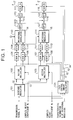
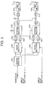
- FIG. 5 exemplifies an adaptive array antenna transmitting apparatus.
- this apparatus performs modulation on a transmission signal S by means of a baseband modulator 501, and then performs vector multiplication with different complex weight coefficients W 1 and W 2 by means of vector multipliers 502 and 503.
- the signals resulting from the multiplication are converted to analog signals by D/A (Digital-to-Analog) converters 504 to 507.
- the analog signals are subjected to orthogonal modulation by orthogonal modulators 508 and 509, and then filtered by band-pass filters 510 to 513.
- the filtered signals are amplified by power amplifiers 514 and 515 and are then transmitted from antennae A and B.
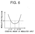
- the orthogonal modulators 508 and 509 used in the above process have a modulation characteristic as shown in FIG. 6 with respect to the input signal level.
- the characteristic is such that the modulation precision becomes equal to or greater than ⁇ , which is a practical range, when the input signal level lies between ( ⁇ - ⁇ 1 ) and ( ⁇ + ⁇ 2 ), and the modulation precision becomes the highest when the input signal level is ⁇ .
- the adaptive array antenna transmitting apparatus transmits a signal multiplied by a complex weight coefficient W 1 antenna by antenna.
- of the complex weight coefficient When the amplitude
- of the complex weight coefficient is too small or too large, therefore, inputs to the orthogonal modulators do not fall in the range from ( ⁇ - ⁇ 1 ) to ( ⁇ + ⁇ 2 ), thereby reducing the modulation precision of the transmitting apparatus.
- a radio transmitting apparatus is designed to properly operate orthogonal modulators by compensating the levels of input signals to the orthogonal modulators within the proper range. More specifically, the radio transmitting apparatus embodying this invention comprises a vector multiplication section for multiplying a transmission baseband modulation signal by a complex weight coefficient for directivity control; an orthogonal modulation section for performing orthogonal modulation on an output signal of the vector multiplication section; a gain control section for performing gain control on an input signal to the orthogonal modulation section based on a gain determined from the complex weight coefficient and a previously measured modulation precision characteristic of the orthogonal modulation section; and a transmission section for amplifying and transmitting an output of the orthogonal modulation section.
- the gain control section may perform gain control on the output signal of the vector multiplication section, or may perform gain control on the complex weight coefficient to be input to the vector multiplication section.
- the transmission section amplifies the signal level attenuated by the gain control to a proper output. This permits a transmission output from each antenna to be kept at the proper level.
- the transmission output is optimized by performing gain control on a power amplifier in the transmission section with the reciprocal of the control gain for the input signal to the orthogonal modulation section.
- CDMA transmission can be carried out at the proper transmission level.
- transmission power control may be executed code by code.
- a radio transmitting apparatus is designed to temporarily acquire a control gain, and compensate an amount of shift from the input signal level which provides the optimal operation of each orthogonal modulator, to thereby set the control gain again. This can permit every orthogonal modulator to perform the optimal operation with respect to every input signal.
- a signal of the proper level can be transmitted by carrying out transmission after performing gain control with the reciprocal of the re-set control gain in the transmission power amplifier.
- Radio transmitting apparatuses according to preferred embodiments of the present invention will now be described specifically with reference to the accompanying drawings. The following description will be given on the premise that transmitting apparatuses of those embodiments are used in CDMA radio communications and are adaptive array antenna transmitting apparatuses which carry out directivity transmission.
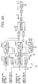
- FIG. 1 is a block diagram of a radio transmitting apparatus according to the first embodiment of this invention.
- the number of antennae is two to simplify the description, the fundamental operation is the same as in a case of using M antennae.
- the input voltage v.s. modulation precision characteristic of an orthogonal modulator as shown in FIG. 10 has previously been measured and known.
- M orthogonal modulators for M antennae it is necessary to measure the characteristics of the individual orthogonal modulators in advance.
- a signal G which is the measured characteristic information of each orthogonal modulator is input to an associated gain controller.
- a transmission signal S1 is input to a baseband modulator 101.
- the baseband modulator 101 modulates the signal S1 and outputs baseband modulation signals S2 and S3.
- Those signals S2 and S3 are respectively input to a vector multiplier 102 for an antenna A and a vector multiplier 103 for an antenna B.
- the vector multipliers 102 and 103 perform vector multiplication of the signals S2 and S3 by complex weight coefficients W 1 and W 2 .
- Gain controllers 105 and 106 perform gain control on the output signal of the vector multiplier 102 with a gain A 1 in accordance with a gain control signal G1 from a gain control amount calculator 104.
- gain controllers 107 and 108 perform gain control on the output signal of the vector multiplier 103 with a gain A 2 in accordance with a gain control signal G2 from the gain control amount calculator 104.
- D/A converters 109 to 112 convert those gain control signals to analog signals. Some of those analog signals are converted to an IF frequency signal S4 in an orthogonal modulator 113 by performing orthogonal modulation on the baseband signal of the antenna A, and the other analog signals are converted to an IF frequency signal S5 in an orthogonal modulator 114 by performing orthogonal modulation on the baseband signal of the antenna B.
- a mixer 115 converts the IF frequency signal S4 of the antenna A to a transmission frequency signal.
- a gain controller 117 as a power amplifier performs gain control on the transmission frequency signal with a gain B 1 in accordance with a gain control signal G3 from the gain control amount calculator 104, and transmits the resultant signal from the antenna A.
- a mixer 116 converts the IF frequency signal S5 of the antenna B to a transmission frequency signal.
- a gain controller 118 as a power amplifier performs gain control on the transmission frequency signal with a gain B 2 in accordance with a gain control signal G4 from the gain control amount calculator 104, and transmits the resultant signal from the antenna B.
- BPFs (Band-Pass Filters) 119 and 121 before the mixers 115 and 116 are frequency filters for removing unnecessary signals after orthogonal modulation
- BPFs 120 and 122 following the mixers 115 and 116 are frequency filters for removing unnecessary signals after signal mixing.
- the gain control amount calculator 104 computes the gains A 1 and B 1 in the gain control for the antenna A and the gains A 2 and B 2 in the gain control for the antenna B as follows.
- the gain control amount calculator 104 calculates the gains A 1 and B 1 based on the characteristic information of the orthogonal modulator 113 and the complex weight coefficient W 1 . Assuming that the orthogonal modulator 113 is so adjusted that when the optimal input voltage value is ⁇ 1 and
- 1, the outputs of the D/A converters 109 and 110 become ⁇ 1 , the gain controller 104 performs control such that the gain A 1 becomes 1/
- the gains A 2 and B 2 are calculated based on the characteristic information of the orthogonal modulator 114 and the complex weight coefficient W 2 , and the gain A 2 becomes 1/
- QPSK Quadrature Phase Shift Keying
- mean transmission power becomes a value given by an equation (3) in which the first term indicates the power of a signal point (a, a) of the QPSK modulation system, the second term indicates the power of a signal point (a, -a) of the QPSK modulation system, the third term indicates the power of a signal point (-a, -a) of the QPSK modulation system, and the fourth term indicates the power of a signal point (-a, a) of the QPSK modulation system.
- the numbers of the signal points are k 1 , k 2 , k 3 and k 4 , respectively, and the total number of signal points becomes K as shown in an equation (4).
- W is a complex number
- mean transmission power changes from the value given by the equation (3) to the double value given by the equation (5) by multiplying the power by the weight coefficient.
- W'' 2 the amplitude changes by a factor of
- the radio transmitting apparatus embodying this invention performs gain control A m on the input signal to each orthogonal modulator and performs gain control B m to return the signal level to the original signal level before transmission, so that the level of the input signal to the orthogonal modulator lies within a range from ( ⁇ - ⁇ 1 ) to ( ⁇ + ⁇ 2 ), thereby ensuring high-output transmission while allowing the orthogonal modulator to operate with the optimal precision.
- FIG. 2 presents a block diagram of a radio transmitting apparatus according to the second embodiment of this invention. While the gain controllers 105 and 106, located before the associated D/A converters, carry out gain control with the gains A 1 and A 2 in the first embodiment, gain controllers 205 and 207 carry out gain control on complex weight coefficients W 1 and W 2 to be input to vector multipliers 202 and 203, with the gains A 1 and A 2 in the second embodiment.
- the gain controller 205 executes gain control by dividing the complex weight coefficient W 1 by control information G1 from a gain control amount calculator 204.
- the gain controller 207 executes gain control by dividing the complex weight coefficient W 2 by control information G2 from the gain control amount calculator 204.
- a gain controller 217 as a power amplifier performs gain control on the transmission signal of the antenna A with a gain B 1 in accordance with a gain control signal G3 from the gain control amount calculator 204
- a gain controller 218 as a power amplifier performs gain control on the transmission signal of the antenna B with a gain B 2 in accordance with a gain control signal G4 from the gain control amount calculator 204 as per the first embodiment.
- the gains A 1 and A 2 and the gains B 1 and B 2 in the gain controllers 205, 207, 217 and 218 are determined by the following equations (6) and (7).
- a m 1/
- B m
- gain control is previously performed on the complex weight coefficients W 1 and W 2 , so that the processes in the vector multipliers 202 and 203 need not alter the amplitude and have only to rotate the phase. It is thus possible to set the range for an input signal to an orthogonal modulator constant with a simple circuit structure.
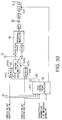
- FIG. 3 presents a block diagram of a radio transmitting apparatus according to the third embodiment of this invention.
- the description of this embodiment will discuss an adaptive array antenna transmitting apparatus of a multiple code CDMA communications system. To simplify the description, we let the number of antennae be two and the number of codes be two.
- a complex weight coefficient for a code n for the antenna m is generally denoted by W m,n .
- Radio transmitting apparatuses execute gain control by compensating the amplitude of a complex weight coefficient as per the second embodiment.
- the gain control scheme in the third embodiment may however employ either the gain control performed directly before a D/A converter after the execution of vector multiplication as done in the first embodiment or the scheme of compensating the amplitude of a complex weight coefficient which is used in vector multiplication as done in the second embodiment.
- baseband modulators 301a and 301b receive a transmission signal S1 and arranges it at signal points for transmission. Then, the baseband modulator 301a sends a baseband modulation signal S2 of a code 1 to a vector multiplier 302a for the antenna A and a vector multiplier 303a for the antenna B. Likewise, the baseband modulator 301b sends a baseband modulation signal S3 of a code 2 to a vector multiplier 302b for the antenna A and a vector multiplier 303b for the antenna B.
- gain controllers 305 and 306 perform gain control on complex weight coefficients W 1,1 and W 1,2 of the code 1 and code 2 to be transmitted from the antenna A in accordance with a control signal G1 from a gain control amount calculator 304, and send the gain-controlled complex weight coefficients W 1,1 and W 1,2 to the vector multipliers 302a and 302b.
- Gain controllers 307 and 308 perform gain control on complex weight coefficients W 2,1 and W 2,2 of the code 1 and code 2 to be transmitted from the antenna B in accordance with a control signal G2 from the gain control amount calculator 304, and send the gain-controlled complex weight coefficients W 2,1 and W 2,2 to the vector multipliers 303a and 303b.
- the vector multipliers 302a, 302b, 303a and 303b perform vector multiplication of the baseband modulation signals S2 and S3 and the gain-controlled complex weight coefficients WG1, WG2, WG3 and WG4.
- an adder 323 adds the outputs of the vector multipliers 302a and 302b of two separate systems, which become the transmission signals from the antenna A.
- An adder 324 adds the outputs of the vector multipliers 303a and 303b of two separate systems, which become the transmission signals from the antenna B.
- Gain controllers 317 and 318 which are power amplifiers, up-convert the D/A converted signals of those added signals to the transmission frequency band before transmission from the antennae A and B as done in the first embodiment.
- the control gain B m of the gain controllers 317 and 318 is determined by the gain control amount calculator 304 based on the following equation (8).
- the transmission signal is what is obtained by adding a signal of the code 1 multiplied by the complex weight coefficient W 1,1 and a signal of the code 2 multiplied by the complex weight coefficient W 1,2 .
- the amplitude is ⁇ 2 x a
- Four QPSK signal points for each code thus amount to a total of sixteen points.
- the mean power is calculated from an equation (9).
- This equation is derived by using such a property that the combinations (11, 12) of the phases of the code 1 and the code 2 will occur equally likely with a probability of 1/16. It is apparent that the computation result differs from the value of the mean power when the weight coefficients shown in the equation (3) are not used. Thus, a change in amplitude takes a value given by the equation (9).
- PSK Phase Shift Keying
- APSK Amplitude Phase Shift Keying
- QAM Quadrature Amplitude Modulation
- the gain controllers 305 and 306 perform gain control using the gains A 1 which are acquired by respectively dividing the complex weight coefficient W 1,1 of the code 1 for the antenna A to the vector multiplier 302a and the complex weight coefficient W 1,2 of the code 2 to the vector multiplier 302b by an equation (10).
- transmission is executed after amplifying the gain B 1 by an amount given by an equation (11) in the gain controller 317.
- gain control is executed using the gains A 2 which are acquired by respectively dividing the complex weight coefficient W 2,1 of the code 1 for the antenna B to the vector multiplier 303a and the complex weight coefficient W 2,2 of the code 2 to the vector multiplier 303b by an equation (12).
- transmission is executed after amplifying the gain B 2 by an amount given by an equation (13) in the gain controller 318.
- a m denotes the gain of gain control A m,1 for the code 1 and gain control A m,2 for the code 2 and B m denotes the gain of the gain controllers 317 and 318, those gains can generally be expressed by the following equations (14) and (15).
- a m 1/
- 2 B m 1/ A m
- control gains A m and B m are respectively expressed by the following equations (16) and (17).
- 2 B m 1/ A m
- the third embodiment is adapted to an adaptive array antenna transmitting apparatus which transmits multiple codes of the CDMA communications system in a multiplexed form.
- the radio transmitting apparatus of the third embodiment executes gain control in consideration of the increase in mean value which has resulted from the multiplication by the weight coefficient, so that all the orthogonal modulators can perform the optimal operation with respect to every input signal.
- the radio transmitting apparatus of the third embodiment performs gain control to keep the input to each orthogonal modulator constant by multiplying the complex weight coefficient W m,n of a code n for every m antennae by the coefficient shown in the equation (16). That is, the complex weight coefficient of each complex multiplier becomes what is given by an equation (18).
- the compensation for the equation (18) is to acquire the desired modulation precision based on the previously measured characteristic of each orthogonal modulator. Through this compensation, an orthogonal modulator having the characteristic as shown in FIG. 6 properly operates within the input range from ( ⁇ - ⁇ 1 ) to ( ⁇ + ⁇ 2 ).
- the gain control amount calculator 304 determines the gain control information G1 and G2 from the characteristic information G of the orthogonal modulators and complex weight coefficients W 1,1 , W 1,2 , W 2,1 and W 2,2 using the equationan (14).
- the gain controllers 305, 306, 307 and 308 compute the values of the above individual complex weight coefficients in accordance with the equation (18). In accordance with which one of conditions (1) to (3) the computation results fall, the gain controllers 305, 306, 307 and 308 recalculate the gain control information G1 and G2.
- Condition (1) The case where there is an overflowing coefficient among the entire compensated complex weight coefficients for the m-th antenna.
- the complex weight coefficients are determined by an equation (19).
- the control gain is set to the values that are given by equations (20) and (21).
- Those equations mean compensation to make the mean value of the inputs to the orthogonal modulators to ( ⁇ - ⁇ 1 ).
- This compensation increases the complex weight coefficients by a factor of ( ⁇ - ⁇ 1 )/ ⁇ when the mean value of the inputs to the orthogonal modulators is set to ⁇ . Therefore, the complex weight coefficients do not overflow and the modulation precision does not get lower.
- the complex weight coefficients are set to a maximum but non- overflowing value.
- 2 ⁇ ⁇ -Ddelta; 1 ⁇ B m 1/ A m
- Condition (2) The case where there is an underflowing coefficient among the entire compensated complex weight coefficients for the m-th antenna.
- control gain is determined by equations (23) and (24).
- Condition (3) The case where none of the compensated complex weight coefficients for the m-th antenna overflow or underflow.
- the proper signal level can be acquired by increasing the gain by a factor of ⁇ /( ⁇ - ⁇ 1 ) in any gain controller serving as a power amplifier at the time of transmission.
- the radio transmitting apparatus of the fourth embodiment can always keep the level of the input signal to the associated orthogonal modulator in the proper range by recomputing the control gain.
- the gain of a transmission power amplifier is reduced to suppress undesired interference or reduce the amount of power used, or is increased to retain the line quality.
- This control is generally called transmission power control.
- the fifth embodiment is directed to an adaptive array antenna transmitting apparatus which performs transmission power control.
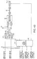
- FIG. 4 is a block diagram of a radio transmitting apparatus according to the fifth embodiment. This radio transmitting apparatus is the same as that of the third embodiment except for the operation of a gain control amount calculator 404.
- the gain control amount calculator 404 receives the characteristic information G of orthogonal modulators, the complex weight coefficients W 1,1 W 1,2 , W 2,1 and W 2,2 , the transmission power control information C1 of the code 1 and the transmission power control information C2 of the code 2. Then, the gain control amount calculator 404 determines gain control information G1 and G2 to gain controllers 405 and 406 using an equation (28) given below and determines gain control information G3 and G4 to gain controllers 407 and 408 using an equation (29) given below.
- the control information consists of the complex weight coefficient W m,n and transmission power Cn with respect to the antenna m and code n.
- the input to each orthogonal modulator is increased by a factor of ??? as shown in an equation (27).
- n 1 N
- the gain controllers 405, 406, 407 and 408 perform gain control on the complex weight coefficients, antenna by antenna, with the gain control amount A m given by an equation (28), and any gain controller serving as a transmission power amplifier executes gain control with the gain control amount B m given by an equation (29).
- the radio transmitting apparatus of the fifth embodiment compensates for a variation in orthogonal modulator input which occurs as the transmission power control is carried out code by code. Even in executing transmission power control in adaptive array antenna transmission, therefore, transmission can be carried out with the proper precision maintained in the multiplication of weight coefficients for adaptive array antenna transmission while the orthogonal modulators are operated with the proper precision.
- the radio transmitting apparatuses of the above-described embodiments controls gain controllers serving as power amplifiers with the control gain B m .
- Power amplifiers however cannot follow up a variation in control gain B m rapidly depending on their operational characteristics.
- the sixth embodiment is designed to overcome this shortcoming.
- circuit structure of the radio transmitting apparatus according to the sixth embodiment is the same as that of the first embodiment except for the operation of the gain control amount calculator 104, the description will be given with reference to FIG. 1.
- the gain control amount calculator 104 receives the characteristic information G of the orthogonal modulators and complex weight coefficients W 1,1 and W 1,2 , and calculates temporary control gain amounts G1, G2, G3 and GT4 based on the equations (3) and (4).
- the first one of the determination procedures is to set the gain control amount which the associated power amplifier can follow up as a threshold value. Then, when the computed gain control amount is less than the threshold value, it is determined that the power amplifier can follow up the gain control amount. When the computed gain control amount is equal to or greater than the threshold value, on the other hand, it is determined that the power amplifier cannot follow up the gain control amount.
- the value of the gain control amount B m is compared with the threshold value P of the gain control amount based on which the followability of the associated power amplifier is to be determined.
- the gain control amount B m is smaller than the threshold value P, it means that the power amplifier can follow up the amount, so that the gain control amount calculator 104 sets the gain of the power amplifier to the gain control amount B m and operates the power amplifier with that gain.
- the gain control amount B m is greater than the threshold value P based on which the followability of the associated power amplifier is to be determined, it means that the power amplifier cannot follow up the amount, so that the gain control amount calculator 104 sets the gain of the power amplifier to the followable threshold value P and operates the power amplifier with that gain.
- the radio transmitting apparatus of the sixth embodiment sets the control gain of each vector multiplier while giving some relativity with the control gain of the associated power amplifier.
- the gain control amount calculator 104 compensates the gain control characteristic of the power amplifier by setting the control gain B m of the power amplifier step by step, and re-setting the value of the control gain A m of the vector multiplier in association with the control gain B m of the power amplifier.
Abstract
Description
Claims (13)
- A radio transmitting apparatus comprising:vector multiplication means(102,103) for multiplying a transmission baseband modulation signal by a complex weight coefficient for directivity control;orthogonal modulation means(113,114) for performing orthogonal modulation on an output signal of said vector multiplication means(102,103);gain control means(104) for performing gain control on an input signal to said orthogonal modulation means(113,114) based on a gain determined from said complex weight coefficient and a previously measured modulation precision characteristic of said orthogonal modulation means(113,114); andtransmission means for amplifying and transmitting an output of said orthogonal modulation means (113,114).
- The radio transmitting apparatus according to claim 1, wherein said gain control means executes gain control on said output signal of said vector multiplication means.
- The radio transmitting apparatus according to claim 1, wherein said gain control means performs gain control on said complex weight coefficient to be input to said vector multiplication means.
- The radio transmitting apparatus according to claim 1, wherein said transmission means executes transmission after performing gain control on a reciprocal of a control gain with respect to an input signal to said orthogonal modulation means.
- The radio transmitting apparatus according to claim 4, wherein said gain control means performs gain control on a transmission signal of each code in a code division multiple access (CDMA) system.
- The radio transmitting apparatus according to claim 5, wherein for m antennae (m = 1 to M), n users (n = 1 to N) and complex weight coefficients Wm,n, said transmission means controls a gain of a power amplifier based on an estimated value of a change in a mean value of an input signal to said orthogonal modulation means which is determined by a mean square of a power of complex weight coefficients for N users.
- The radio transmitting apparatus according to claim 5, wherein said gain control means performs gain control on an input signal to said orthogonal modulation means using a gain determined from said complex weight coefficient, said previously measured modulation precision characteristic of said orthogonal modulation means and a transmission power control amount for each code.
- The radio transmitting apparatus according to claim 4, wherein said for m antennae (m = 1 to M), n users (n = 1 to N), complex weight coefficients Wm,n and a transmission power control amount Cn, said transmission means controls a gain of a transmission power amplifier based on an estimated value of a change in a mean value of an input signal to said orthogonal modulation means which is determined by a mean square of a power of a product of complex weight coefficients for N users and a transmission power control amount.
- A radio transmitting apparatus comprising:vector multiplication means(102,103) for multiplying a transmission baseband modulation signal by a complex weight coefficient for directivity control;orthogonal modulation means(113,114) for performing orthogonal modulation on an output signal of said vector multiplication means(102,103);transmission means for amplifying and transmitting an output of said orthogonal modulation means(113,114); andgain control means(104) for performing gain control on an input signal to said orthogonal modulation means(113,114) based on a gain determined from said complex weight coefficient and a previously measured modulation precision characteristic of said orthogonal modulation means(113,114),
whereby said gain control means(104) executes gain compensation to increase a control gain based on an input level versus modulation precision of said orthogonal modulation means(113,114) if said vector multiplication means(102,103) underflows when using a complex weight coefficient after gain control, and executes gain compensation to decrease said control gain based on said input level versus modulation precision of said orthogonal modulation means(113,114) if said vector multiplication means(102,103) overflows when using said complex weight coefficient after gain control. - A gain control method for a radio transmitting apparatus comprising the steps of:performing gain control on an input signal to an orthogonal modulator in such a way that a level of said input signal falls within a proper operation range of said orthogonal modulator;performing orthogonal modulation on a gain-controlled signal; andexecuting transmission after performing gain control on a signal after orthogonal modulation with a reciprocal of a control gain for said input signal to said orthogonal modulator.
- The gain control method according to claim 10, wherein said gain control step performs gain control on a signal resulting from vector multiplication of a transmission baseband modulation signal by a complex weight coefficient for directivity control.
- The gain control method according to claim 10, wherein said gain control step performs gain control on a complex weight coefficient for directivity control, by which a transmission baseband modulation signal is to be multiplied.
- The gain control method according to claim 11 or 12, wherein said gain control step includes the steps of:determining if underflow or overflow occurs at a time of performing said vector multiplication; andcompensating a control gain when underflow or overflow is determined to occur when using a complex weight coefficient after gain control.
Applications Claiming Priority (3)
| Application Number | Priority Date | Filing Date | Title |
|---|---|---|---|
| JP9030697 | 1997-03-25 | ||
| JP90306/97 | 1997-03-25 | ||
| JP9030697A JP3537988B2 (en) | 1997-03-25 | 1997-03-25 | Wireless transmitter |
Publications (2)
| Publication Number | Publication Date |
|---|---|
| EP0867970A2 true EP0867970A2 (en) | 1998-09-30 |
| EP0867970A3 EP0867970A3 (en) | 2000-12-06 |
Family
ID=13994866
Family Applications (1)
| Application Number | Title | Priority Date | Filing Date |
|---|---|---|---|
| EP19980104942 Withdrawn EP0867970A3 (en) | 1997-03-25 | 1998-03-18 | Radio transmitting apparatus and gain control method for the same |
Country Status (6)
| Country | Link |
|---|---|
| US (1) | US6118987A (en) |
| EP (1) | EP0867970A3 (en) |
| JP (1) | JP3537988B2 (en) |
| KR (1) | KR100303371B1 (en) |
| CN (1) | CN1119839C (en) |
| CA (1) | CA2232252C (en) |
Cited By (1)
| Publication number | Priority date | Publication date | Assignee | Title |
|---|---|---|---|---|
| FR2816161A1 (en) * | 2000-10-31 | 2002-05-03 | Mitsubishi Electric Inf Tech | METHOD FOR OBTAINING ANTENNA GAIN |
Families Citing this family (14)
| Publication number | Priority date | Publication date | Assignee | Title |
|---|---|---|---|---|
| US6628630B1 (en) | 1997-04-15 | 2003-09-30 | Matsushita Electric Industrial Co., Ltd. | Spread spectrum communication method |
| JP3462388B2 (en) * | 1998-04-28 | 2003-11-05 | 松下電器産業株式会社 | Wireless communication device |
| JP4287536B2 (en) * | 1998-11-06 | 2009-07-01 | パナソニック株式会社 | OFDM transmitter / receiver and OFDM transmitter / receiver method |
| JP3317259B2 (en) * | 1998-12-17 | 2002-08-26 | 日本電気株式会社 | Baseband signal multiplexing circuit and transmission level control method thereof |
| JP3641961B2 (en) * | 1999-02-01 | 2005-04-27 | 株式会社日立製作所 | Wireless communication device using adaptive array antenna |
| JP3592980B2 (en) * | 1999-06-29 | 2004-11-24 | 株式会社東芝 | Transmission circuit and wireless transmission device |
| US6993066B2 (en) * | 2000-03-13 | 2006-01-31 | Matsushita Electric Industrial Co., Ltd. | Transmitting apparatus and gain compensating method |
| US8363744B2 (en) | 2001-06-10 | 2013-01-29 | Aloft Media, Llc | Method and system for robust, secure, and high-efficiency voice and packet transmission over ad-hoc, mesh, and MIMO communication networks |
| CN100382457C (en) * | 2003-02-26 | 2008-04-16 | 日本无线株式会社 | Array antenna communication device |
| US7961813B2 (en) * | 2005-09-06 | 2011-06-14 | Nihon University | Multi-value modulation/demodulation method and multi-value modulation/demodulation device |
| CN103338064B (en) * | 2013-06-06 | 2016-11-09 | 四川大学 | Pre-channel smart antenna MIMO emitter and wireless signal transmitting method |
| JP6269834B2 (en) | 2014-07-22 | 2018-01-31 | 日本電気株式会社 | Wireless transmission apparatus and wireless transmission method |
| CN108921292B (en) * | 2018-05-02 | 2021-11-30 | 东南大学 | Approximate computing system for deep neural network accelerator application |
| US10804942B2 (en) | 2018-05-24 | 2020-10-13 | Analog Devices, Inc. | State-machine based body scanner imaging system |
Citations (5)
| Publication number | Priority date | Publication date | Assignee | Title |
|---|---|---|---|---|
| US4199723A (en) * | 1978-02-24 | 1980-04-22 | Rockwell International Corporation | Automatic modulation control apparatus |
| WO1992008297A1 (en) * | 1990-10-24 | 1992-05-14 | Motorola, Inc. | An apparatus and method for varying a signal in a transmitter of a transceiver |
| US5193223A (en) * | 1990-12-20 | 1993-03-09 | Motorola, Inc. | Power control circuitry for a TDMA radio frequency transmitter |
| JPH08321748A (en) * | 1995-05-24 | 1996-12-03 | Sony Corp | Pseudo noise code generating circuit |
| WO1997000543A1 (en) * | 1995-06-16 | 1997-01-03 | Watkins-Johnson Company | Method and apparatus for adaptive transmission beam forming in a wireless communication system |
Family Cites Families (3)
| Publication number | Priority date | Publication date | Assignee | Title |
|---|---|---|---|---|
| DE69319689T2 (en) * | 1992-10-28 | 1999-02-25 | Atr Optical And Radio Communic | Device and method for controlling a group antenna with a plurality of antenna elements |
| JP2572200B2 (en) * | 1994-03-03 | 1997-01-16 | 株式会社エイ・ティ・アール光電波通信研究所 | Array antenna control method and control device |
| US5862460A (en) * | 1996-09-13 | 1999-01-19 | Motorola, Inc. | Power control circuit for a radio frequency transmitter |
-
1997
- 1997-03-25 JP JP9030697A patent/JP3537988B2/en not_active Expired - Fee Related
-
1998
- 1998-03-16 CA CA 2232252 patent/CA2232252C/en not_active Expired - Fee Related
- 1998-03-18 EP EP19980104942 patent/EP0867970A3/en not_active Withdrawn
- 1998-03-19 US US09/044,174 patent/US6118987A/en not_active Expired - Fee Related
- 1998-03-25 CN CN98105863A patent/CN1119839C/en not_active Expired - Fee Related
- 1998-03-25 KR KR1019980010308A patent/KR100303371B1/en not_active IP Right Cessation
Patent Citations (5)
| Publication number | Priority date | Publication date | Assignee | Title |
|---|---|---|---|---|
| US4199723A (en) * | 1978-02-24 | 1980-04-22 | Rockwell International Corporation | Automatic modulation control apparatus |
| WO1992008297A1 (en) * | 1990-10-24 | 1992-05-14 | Motorola, Inc. | An apparatus and method for varying a signal in a transmitter of a transceiver |
| US5193223A (en) * | 1990-12-20 | 1993-03-09 | Motorola, Inc. | Power control circuitry for a TDMA radio frequency transmitter |
| JPH08321748A (en) * | 1995-05-24 | 1996-12-03 | Sony Corp | Pseudo noise code generating circuit |
| WO1997000543A1 (en) * | 1995-06-16 | 1997-01-03 | Watkins-Johnson Company | Method and apparatus for adaptive transmission beam forming in a wireless communication system |
Non-Patent Citations (1)
| Title |
|---|
| PATENT ABSTRACTS OF JAPAN vol. 1997, no. 04, 30 April 1997 (1997-04-30) -& JP 08 321748 A (SONY CORP), 3 December 1996 (1996-12-03) -& US 5 835 488 A (SUGITA) 10 November 1998 (1998-11-10) * |
Cited By (3)
| Publication number | Priority date | Publication date | Assignee | Title |
|---|---|---|---|---|
| FR2816161A1 (en) * | 2000-10-31 | 2002-05-03 | Mitsubishi Electric Inf Tech | METHOD FOR OBTAINING ANTENNA GAIN |
| EP1204162A1 (en) * | 2000-10-31 | 2002-05-08 | Mitsubishi Electric Information Technology Centre Europe B.V. | Method for obtaining an antenna gain function |
| US7079606B2 (en) | 2000-10-31 | 2006-07-18 | Mitsubishi Denki Kabushiki Kaisha | Method of obtaining an antenna gain |
Also Published As
| Publication number | Publication date |
|---|---|
| KR19980080649A (en) | 1998-11-25 |
| JP3537988B2 (en) | 2004-06-14 |
| KR100303371B1 (en) | 2001-09-24 |
| CA2232252A1 (en) | 1998-09-25 |
| CN1119839C (en) | 2003-08-27 |
| JPH10270929A (en) | 1998-10-09 |
| US6118987A (en) | 2000-09-12 |
| CN1202744A (en) | 1998-12-23 |
| CA2232252C (en) | 2003-01-14 |
| EP0867970A3 (en) | 2000-12-06 |
Similar Documents
| Publication | Publication Date | Title |
|---|---|---|
| US6118987A (en) | Radio transmitting apparatus and gain control method for the same based on complex weight coefficients and modulation precision characteristics | |
| US6252915B1 (en) | System and method for gaining control of individual narrowband channels using a wideband power measurement | |
| EP1276233B1 (en) | Apparatus and method for controlling transmission power in a mobile communication system | |
| KR100292926B1 (en) | Sir measurement apparatus | |
| US6414946B1 (en) | Adaptive downlink transmission power control arbiter | |
| EP1062711B1 (en) | Adaptive cancellation of fixed interferers | |
| US7248656B2 (en) | Digital convertible radio SNR optimization | |
| US7142616B2 (en) | Front end processor for data receiver and nonlinear distortion equalization method | |
| US5487091A (en) | Method for determining signal usability in a diversity receiver | |
| JPS6349928B2 (en) | ||
| EP1011207B1 (en) | Transmission power control of baseband signal depending on the number of transmission codes | |
| EP1869779B1 (en) | Receiver for receipt and demodulation of a frequency modulated rf signal and method of operation therein | |
| EP1143559B1 (en) | Adaptive array apparatus for correcting phase for forming directional pattern and correction method | |
| CA2069476C (en) | An apparatus and method for varying a signal in a transmitter of a transceiver | |
| JP2002305489A (en) | Code multiplex signal transmission apparatus | |
| GB2337169A (en) | An adaptive predistorter for an amplifier | |
| US9660732B2 (en) | Power adjustment of in-phase and quadrature components at a coherent optical receiver | |
| JP4185601B2 (en) | Transmission power control method, transmission power control apparatus, and base station including the same | |
| US6999734B2 (en) | Nonlinear compensating circuit, base-station apparatus, and transmission power clipping method | |
| JP3473693B2 (en) | Method and apparatus for adjusting transmission power of CDMA terminal | |
| JP2001102996A (en) | Base station device and radio communication method | |
| JPH11186946A (en) | Diversity receiver and agc circuit used for the receiver | |
| JPH098766A (en) | Quadrature frequency dividing multiplex receiver | |
| JP2003152593A (en) | Transmission peak limiting circuit | |
| JPH0524690B2 (en) |
Legal Events
| Date | Code | Title | Description |
|---|---|---|---|
| PUAI | Public reference made under article 153(3) epc to a published international application that has entered the european phase |
Free format text: ORIGINAL CODE: 0009012 |
|
| AK | Designated contracting states |
Kind code of ref document: A2 Designated state(s): DE FR GB |
|
| AX | Request for extension of the european patent |
Free format text: AL;LT;LV;MK;RO;SI |
|
| PUAL | Search report despatched |
Free format text: ORIGINAL CODE: 0009013 |
|
| AK | Designated contracting states |
Kind code of ref document: A3 Designated state(s): AT BE CH DE DK ES FI FR GB GR IE IT LI LU MC NL PT SE |
|
| AX | Request for extension of the european patent |
Free format text: AL;LT;LV;MK;RO;SI |
|
| RIC1 | Information provided on ipc code assigned before grant |
Free format text: 7H 01Q 3/26 A, 7H 04B 7/005 B |
|
| 17P | Request for examination filed |
Effective date: 20010118 |
|
| AKX | Designation fees paid |
Free format text: DE FR GB |
|
| 17Q | First examination report despatched |
Effective date: 20030909 |
|
| GRAP | Despatch of communication of intention to grant a patent |
Free format text: ORIGINAL CODE: EPIDOSNIGR1 |
|
| STAA | Information on the status of an ep patent application or granted ep patent |
Free format text: STATUS: THE APPLICATION IS DEEMED TO BE WITHDRAWN |
|
| 18D | Application deemed to be withdrawn |
Effective date: 20060711 |