EP0872834B1 - Recorder using information signal recording medium - Google Patents
Recorder using information signal recording medium Download PDFInfo
- Publication number
- EP0872834B1 EP0872834B1 EP97943162A EP97943162A EP0872834B1 EP 0872834 B1 EP0872834 B1 EP 0872834B1 EP 97943162 A EP97943162 A EP 97943162A EP 97943162 A EP97943162 A EP 97943162A EP 0872834 B1 EP0872834 B1 EP 0872834B1
- Authority
- EP
- European Patent Office
- Prior art keywords
- recording
- disc
- unit
- tuner
- recording medium
- Prior art date
- Legal status (The legal status is an assumption and is not a legal conclusion. Google has not performed a legal analysis and makes no representation as to the accuracy of the status listed.)
- Expired - Lifetime
Links
- 238000001514 detection method Methods 0.000 claims description 25
- 230000000694 effects Effects 0.000 claims description 5
- 230000003287 optical effect Effects 0.000 description 22
- 230000005236 sound signal Effects 0.000 description 16
- 230000006870 function Effects 0.000 description 6
- 230000002401 inhibitory effect Effects 0.000 description 5
- 239000004973 liquid crystal related substance Substances 0.000 description 3
- 238000000034 method Methods 0.000 description 3
- 230000008569 process Effects 0.000 description 3
- 230000002035 prolonged effect Effects 0.000 description 3
- 238000005070 sampling Methods 0.000 description 3
- 230000003442 weekly effect Effects 0.000 description 3
- 238000010586 diagram Methods 0.000 description 2
- 230000007246 mechanism Effects 0.000 description 2
- 241000478345 Afer Species 0.000 description 1
- 230000008859 change Effects 0.000 description 1
- 230000000593 degrading effect Effects 0.000 description 1
- 239000000696 magnetic material Substances 0.000 description 1
- 230000005415 magnetization Effects 0.000 description 1
- 239000002184 metal Substances 0.000 description 1
- 229920003002 synthetic resin Polymers 0.000 description 1
- 239000000057 synthetic resin Substances 0.000 description 1
Images


Classifications
-
- G—PHYSICS
- G11—INFORMATION STORAGE
- G11B—INFORMATION STORAGE BASED ON RELATIVE MOVEMENT BETWEEN RECORD CARRIER AND TRANSDUCER
- G11B27/00—Editing; Indexing; Addressing; Timing or synchronising; Monitoring; Measuring tape travel
- G11B27/002—Programmed access in sequence to a plurality of record carriers or indexed parts, e.g. tracks, thereof, e.g. for editing
-
- G—PHYSICS
- G11—INFORMATION STORAGE
- G11B—INFORMATION STORAGE BASED ON RELATIVE MOVEMENT BETWEEN RECORD CARRIER AND TRANSDUCER
- G11B17/00—Guiding record carriers not specifically of filamentary or web form, or of supports therefor
- G11B17/22—Guiding record carriers not specifically of filamentary or web form, or of supports therefor from random access magazine of disc records
- G11B17/225—Guiding record carriers not specifically of filamentary or web form, or of supports therefor from random access magazine of disc records wherein the disks are transferred from a fixed magazine to a fixed playing unit using a moving carriage
-
- G—PHYSICS
- G11—INFORMATION STORAGE
- G11B—INFORMATION STORAGE BASED ON RELATIVE MOVEMENT BETWEEN RECORD CARRIER AND TRANSDUCER
- G11B19/00—Driving, starting, stopping record carriers not specifically of filamentary or web form, or of supports therefor; Control thereof; Control of operating function ; Driving both disc and head
- G11B19/02—Control of operating function, e.g. switching from recording to reproducing
- G11B19/04—Arrangements for preventing, inhibiting, or warning against double recording on the same blank or against other recording or reproducing malfunctions
-
- G—PHYSICS
- G11—INFORMATION STORAGE
- G11B—INFORMATION STORAGE BASED ON RELATIVE MOVEMENT BETWEEN RECORD CARRIER AND TRANSDUCER
- G11B19/00—Driving, starting, stopping record carriers not specifically of filamentary or web form, or of supports therefor; Control thereof; Control of operating function ; Driving both disc and head
- G11B19/02—Control of operating function, e.g. switching from recording to reproducing
- G11B19/08—Control of operating function, e.g. switching from recording to reproducing by using devices external to the driving mechanisms, e.g. coin-freed switch
-
- G—PHYSICS
- G11—INFORMATION STORAGE
- G11B—INFORMATION STORAGE BASED ON RELATIVE MOVEMENT BETWEEN RECORD CARRIER AND TRANSDUCER
- G11B19/00—Driving, starting, stopping record carriers not specifically of filamentary or web form, or of supports therefor; Control thereof; Control of operating function ; Driving both disc and head
- G11B19/02—Control of operating function, e.g. switching from recording to reproducing
- G11B19/12—Control of operating function, e.g. switching from recording to reproducing by sensing distinguishing features of or on records, e.g. diameter end mark
-
- G—PHYSICS
- G11—INFORMATION STORAGE
- G11B—INFORMATION STORAGE BASED ON RELATIVE MOVEMENT BETWEEN RECORD CARRIER AND TRANSDUCER
- G11B27/00—Editing; Indexing; Addressing; Timing or synchronising; Monitoring; Measuring tape travel
- G11B27/02—Editing, e.g. varying the order of information signals recorded on, or reproduced from, record carriers
- G11B27/031—Electronic editing of digitised analogue information signals, e.g. audio or video signals
- G11B27/034—Electronic editing of digitised analogue information signals, e.g. audio or video signals on discs
-
- G—PHYSICS
- G11—INFORMATION STORAGE
- G11B—INFORMATION STORAGE BASED ON RELATIVE MOVEMENT BETWEEN RECORD CARRIER AND TRANSDUCER
- G11B27/00—Editing; Indexing; Addressing; Timing or synchronising; Monitoring; Measuring tape travel
- G11B27/10—Indexing; Addressing; Timing or synchronising; Measuring tape travel
- G11B27/102—Programmed access in sequence to addressed parts of tracks of operating record carriers
- G11B27/105—Programmed access in sequence to addressed parts of tracks of operating record carriers of operating discs
-
- G—PHYSICS
- G11—INFORMATION STORAGE
- G11B—INFORMATION STORAGE BASED ON RELATIVE MOVEMENT BETWEEN RECORD CARRIER AND TRANSDUCER
- G11B27/00—Editing; Indexing; Addressing; Timing or synchronising; Monitoring; Measuring tape travel
- G11B27/10—Indexing; Addressing; Timing or synchronising; Measuring tape travel
- G11B27/19—Indexing; Addressing; Timing or synchronising; Measuring tape travel by using information detectable on the record carrier
- G11B27/28—Indexing; Addressing; Timing or synchronising; Measuring tape travel by using information detectable on the record carrier by using information signals recorded by the same method as the main recording
- G11B27/32—Indexing; Addressing; Timing or synchronising; Measuring tape travel by using information detectable on the record carrier by using information signals recorded by the same method as the main recording on separate auxiliary tracks of the same or an auxiliary record carrier
- G11B27/327—Table of contents
- G11B27/329—Table of contents on a disc [VTOC]
-
- G—PHYSICS
- G11—INFORMATION STORAGE
- G11B—INFORMATION STORAGE BASED ON RELATIVE MOVEMENT BETWEEN RECORD CARRIER AND TRANSDUCER
- G11B27/00—Editing; Indexing; Addressing; Timing or synchronising; Monitoring; Measuring tape travel
- G11B27/10—Indexing; Addressing; Timing or synchronising; Measuring tape travel
- G11B27/34—Indicating arrangements
-
- G—PHYSICS
- G11—INFORMATION STORAGE
- G11B—INFORMATION STORAGE BASED ON RELATIVE MOVEMENT BETWEEN RECORD CARRIER AND TRANSDUCER
- G11B31/00—Arrangements for the associated working of recording or reproducing apparatus with related apparatus
- G11B31/003—Arrangements for the associated working of recording or reproducing apparatus with related apparatus with radio receiver
-
- G—PHYSICS
- G11—INFORMATION STORAGE
- G11B—INFORMATION STORAGE BASED ON RELATIVE MOVEMENT BETWEEN RECORD CARRIER AND TRANSDUCER
- G11B2220/00—Record carriers by type
- G11B2220/20—Disc-shaped record carriers
- G11B2220/25—Disc-shaped record carriers characterised in that the disc is based on a specific recording technology
- G11B2220/2525—Magneto-optical [MO] discs
- G11B2220/2529—Mini-discs
Definitions
- the re-recordable optical discs record information signals, such as audio signals, as digital signals, the playback sound of high sound quality can be produced, while editing or duplication can be done easily without substantially degrading the sound quality.
- EP 0 310 256 A2 discloses a recording and playback apparatus with several digital audio tape cassettes stored on shelves of a magazine.
- a particular embodiment of the apparatus contains a tuner unit through which a reception of plurality of broadcast stations can be set for a plurality of timings.
- An operating unit further allows to record a particular broadcasting program on a predetermined cassette for a particular length of time, whereby the cassette is withdrawn from its storage in a shelf of the magazine for recording and is returned afterwards. For multiple recordings the cassettes are used in a designated order.
- JP 08022665 A A different recording and reproducing device with a disc stocker is disclosed in JP 08022665 A.
- the disc stocker is controlled to enable a timed recording only on the corresponding discs specified by a timer program.
- the controller compares the output signal from the timer and the broadcast reception start time of the timer information held on memory in the storage unit, causes the recording unit to start recording of an output signal from the tuner on the recording medium thus taken out and causes the recording unit to terminate the recording operation for the output signal from the tuner by the recording unit based on the results of comparison of the output signal of the timer and the broadcast reception end time of the timer information held on memory in the storage unit.
- the controller judges whether or not signals are already recorded on a recording medium taken out from the housing section and controls the recording start position of the output signal from the tuner on the recording medium by the recording unit.
- the controller If the controller judges that signals are already recorded on the recording medium taken out from the housing section, the controller causes the recording unit to record an output signal from the tuner as from the recording end position of the previous recording on the recording medium taken out from the recording section.
- the controller If the controller judges that signals are not already recorded on the recording medium taken out from the housing section, the controller causes the recording unit to record an output signal from the tuner as from the recording start position of the previous recording on the recording medium.
- the controller After the end of recording of the output signal from the tuner on the recording medium taken out from the housing section, the controller causes the recording mediums held in the housing section to be sequentially taken out to cause the recording unit to continue the recording operation thereon.
- the housing section has a plurality of housing sites in which to hold the plural recording mediums and the apparatus includes a detection unit for detecting on which of the housing sites of the housing section the recording medium are held.
- the controller controls the recording operation of the recording unit based on the results of detection by the detection unit.
- the storage unit holds on memory the timer information concerning the broadcast reception start time and the broadcast reception end time by a plurality of the tuners and a plurality of items of the reception information concerning the broadcasting stations received by the tuners.
- the storage section also holds on memory the medium information as to on which of the recording mediums housed in the housing section the broadcast received by the tuner is to be recorded.
- the controller controls the tuner by the reception information read out from the storage unit, the controller causing the recording medium designated by the medium information to be taken out from the housing section to record the output signal from the tuner on the recording medium taken out from the housing section.
- the controller controls the reception operation of the tuner based on the reception information from the storage unit and compares the output signal from the timer to the broadcast reception start timing of the timer information held on memory in the storage unit.
- the controller causes a sole recording medium to be taken out from the housing unit based on the results of comparison.
- the controller also causes the recording unit to start recording the output signal of the tuner in a vacant recording area in the first recording area of the recording medium taken out from the housing unit, while also causing the recording unit to terminate recording of the output signal of the tuner based on the results of comparison of the timer output signal to the broadcast reception end time in the storage unit.
- the controller judges whether signals are already recorded on the recording medium taken out from the housing unit based on the table-of-contents information recorded in the second recording area of the recording medium taken out from the housing unit.
- the controller controls the recording start position of the output signal from the tuner on the recording medium by the recording unit based on the results of judgment.
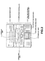
- Fig.2 is a front view showing the disc recording and/or reproducing device in its entirety and an example of an actuating unit.
- Fig.9 is a flow chart showing another example of the operation of the disc recording and/or reproducing device.
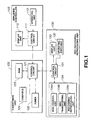
- the disc recording and/or reproducing apparatus employing a recording device according to the present invention, is made up of an amplifier/controller 110, a tuner/timer unit 120 and a disc recording/reproducing unit 130, as shown in Fig.1.
- the respective units exchange the control information of various sorts over a bus line.
- This amplifier/controller 110 includes a control circuit 111, as means for exchanging the control signals over a bus line with various portions of the disc recording and/or reproducing apparatus and for controlling the apparatus in its entirety, an operating unit 112 having switches, dials or the like for commanding and entering the operations as later explained to the control circuit 111 and a display unit 113 made up of a liquid crystal display for displaying the operating states of various parts of the apparatus based on the information from the control circuit 111.
- the display unit 133 includes a liquid crystal display for displaying the operating states of various portions of the apparatus based on the information from the control circuit 131, while the disc exchange and recording/reproducing unit 134 records/reproduces the information signals such as audio signals on or from the plural optical discs.
- the disc exchange and recording/reproducing unit 134 is made up of a disc housing unit 134a for housing plural optical discs on which to record information signals, a disc transporting unit 134b and a recording/reproducing unit 134c.
- the disc transporting unit 134b serves as means for loading and clamping the disc housed in the disc housing unit 134a and for unloading the clamped disc based on control by the control circuit 131, while the recording/reproducing unit 134c is adapted for recording/reproducing information signals on or from the disc transported and clamped by the spindle.
- the amplifier/controller 110 has, in its inside, a control circuit 111 for controlling the tuner/timer unit 120 and the disc recording and/or reproducing unit 130, as described above.
- the amplifier/controller 110 includes the operating unit 112, having various dials or keys for making various inputs to the control circuit 111 and the display unit 113 having a large-sized liquid crystal panel for displaying the operation of the entire disc recording and/or reproducing apparatus via the control circuit 111.
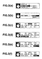
- the setting is made for receiving broadcast programs by timer recording in the disc recording and/or reproducing apparatus for recording the received programs.
- the set data are stored in a RAM 123.
- display is changed to inverted display on menu selection or establishment to indicate the fact of establishment.
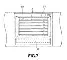
- information signal recording/reproducing apertures 68, 69 for exposing at least portions of the signal recording areas of the magneto-optical disc 65 housed therein to outside radially of the disc.
- These information signal recording/reproducing apertures 68, 69 rectangular in shape, are formed at a mid portion in the left-and-right direction of the main cartridge body portion 64 for extending from a position proximate to the disc table entrance opening 66 sown in Fig.4b to the front end face of the main cartridge body portion 64.
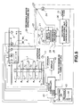
- the recording and/or reproducing unit 20 includes an optical head 21 clamped when, with the disc cartridge having been pulled out by the slider 4a, the elevator 4b is lowered to the home position, and which illuminates a reproducing or recording laser light beam to a disc run in rotation by a spindle motor 25, and a magnetic field modulation head 22 for modulating the magnetic field in the illuminated position by the recording laser light beam from the optical head 21.
- the recording and/or reproducing unit 20 also includes a servo circuit 26 for computing detection signals obtained by a photodetector of the optical head 21 for moving the position of the illuminating spot on the disc along the optical axis or along the disc radius for effecting focusing servo, tracking servo or servo for the spindle motor 25.
- the control circuit 131 of the disc recording/reproducing unit 130 receives a recording start signal, inclusive of the disc number, from the tuner/timer unit 120, in order to check whether or not the designated disc has been stored in the stocker of the disc housing section 134a, more accurately, whether or not the disc has been stored in the designated housing position of the stocker. This check is by the cartridge detector 3 shown in Fig.5. If the designated disc is housed in the stocker, processing transfers to step S26 and, if otherwise, to step spindle motor 25. A similar processing operation is performed if the result of detection of the mistaken recording inhibiting potion 64b has indicated that the recording of the information signals on the disc housed in the disc cartridge is inhibited.
- step S25 the recording operation is canceled, before processing transfers to step S30.
- a control signal is sent from the timepiece unit 124 of the tuner/timer unit 120 via control circuit 121 to the control circuit 111 of the amplifier/controller 110 to turn off the power source of the disc recording and/or reproducing apparatus in its entirety.
- the disc recording/reproducing unit 130 causes the disc transporting unit 134b to restore the disc to the stocker by way of disc unloading.
- information signals an be recorded by the disc recording/reproducing unit 130 on plural recording mediums continuously or separately for the respective mediums at the same time as the plural recording mediums stored in the stocker are exchanged, thus realizing various recording forms in combination with, for example, compact disc exchanging/reproducing apparatus.
- input information signals can be sequentially recorded on the plural recording mediums for sequentially recording the information signals, as the recording mediums are exchanged, for achieving substantially long-time recording.
- recordable disc-shaped recording mediums as the mediums, searching vacant unrecorded areas of the recording mediums based on the information pertinent to the recording contents, such as the TOC information, and sequentially recording the information signals in the vacant areas, thus found, continuous recording across plural recording mediums can be achieved using sem-used recording mediums without erasing the recorded information signals on these semi-used recording mediums.
Description
Claims (12)
- A recording apparatus comprising:characterised in that said controller (121, 131, 111) verifies if previously recorded signals are present on said recording medium (65, 11, 12, 13, 14, 15) and causes said recording unit (130, 134c) to effect the recording in a vacant recording area of said recording medium (65, 11, 12, 13, 14, 15).a tuner (122) for receiving a broadcast program,a timer (124) for generating time information,a storage unit (123) for holding on memory an information concerning at least a starting time and an ending time for a broadcast reception,a housing section (134a) for keeping a plurality of recording mediums (65, 11, 12, 13, 14, 15).a recording unit (130, 134c) for effecting a recording on a recording medium (65, 11, 12, 13, 14, 15) being withdrawn from said housing section (134a),a controller (121, 131, 111) for controlling the operation of said tuner (122) and said recording unit (130, 134c) based on an output signal from said timer (124) and on said information stored in said storage unit (123) by comparing the output signal from the timer (124) with a starting time information for a broadcast reception stored in said storage unit (123) and causing, based on the result of the comparison said recording unit (130, 134c) to start a recording of an output signal from said tuner (122) on a recording medium (65, 11, 12, 13, 14, 15) being withdrawn from said housing section (134a), and by comparing the output signal from the timer (124) with an ending time information for a broadcast reception stored in said storage unit (123) and causing, based on the result of the comparison said recording unit (130, 134c) to terminate a recording of an output signal from said tuner (122) on a recording medium (65, 11, 12, 13, 14, 15) being withdrawn from said housing section (134a),
- A record apparatus according to claim 1,
characterised in that, if said controller (121, 131, 111) identifies no previously recorded signals on said recording medium (65, 11, 12, 13, 14, 15), said controller (121, 131, 111) causes said recording unit (130, 134c) to record an output signal from said tuner (122) starting from the leading end of the recording medium. - A recording apparatus according to claim 1 or 2,
characterised in that, if said controller (121, 131, 111) identifies previously recorded signals on said recording medium (65, 11, 12, 13, 14, 15), said controller (121, 131, 111) causes said recording unit (130, 134c) to record an output signal from the tuner (122) subsequent to the end position of the previous recording. - A recording apparatus according to claim 1, 2 or 3,
characterised in that, when a recording of an output signal of said tuner (122) on a recording medium (65, 11, 12, 13, 14, 15) comes to a close before said ending time for the respective broadcast reception, said controller (121, 131, 111) causes the recording being continued on a subsequent recording medium withdrawn from said housing section (134a). - A recording apparatus according to one of the claims 1 to 4,
characterised in that said housing section (134a) comprises a plurality of housing sites (P1, P2, P3, P4, P5) for keeping said plurality of recording mediums (65, 11, 12, 13, 14, 15) and a detection unit (31, 32, 33, 34, 35) for detecting in each housing site (P1, P2, P3, P4, P5) the presence of a recording medium (65, 11, 12, 13, 14, 15). - A recording apparatus according to claim 5,
characterised in that said controller (121, 131, 111) controls the recording effected by said recording unit (130, 134c) based on the result of a detection by said detection unit (31, 32, 33, 34, 35). - A recording apparatus according to one of the claims 1 to 6,
characterised by
a transporting unit (134b, 4) for withdrawing a recording medium (65, 11, 12, 13, 14, 15) from said housing section (134a) and for transporting said recording medium (65, 11, 12, 13, 14, 15) to said recording unit (130, 134c). - A recording apparatus according to claim 7,
characterised in that said controller (121, 131, 111) controls the operation of said transporting unit (134b, 4) based on the results of a detection from said detection unit (31, 32, 33, 34, 35). - A recording apparatus according to one of the claims 1 to 8,
characterised in that said storage unit (123) holds on memory information concerning the reception of a plurality of broadcast programs, whereby said information concerning the reception of a plurality of broadcast programs comprises a starting time, an ending time, and a reception frequency for each broadcast program of the plurality of broadcast programs. - A recording apparatus according to claim 9,
characterised in that said storage unit (123) holds on memory information regarding an assignment of a particular recording medium (65, 11, 12, 13, 14, 15) out of the plurality of recording mediums (65, 11, 12, 13, 14, 15) to a recording of a particular broadcast program out of the plurality of broadcast programs. - A recording apparatus according to one of the claims 1 to 10,
characterised by
the recording apparatus being adapted for a use of a recording medium (65, 11, 12, 13, 14, 15) with a first recording area for recording an output signal from said tuner (122), and a second recording area for recording a table-of-content information concerning said recording of an output signal from said tuner (122) in said first recording area. - A recording apparatus according to one of the claims 4 to 11,
characterised by
a storage unit (31) for an intermediate storing of an output signal from said tuner (122) when suspending a recording for to exchange a recording medium (65, 11, 12, 13, 14, 15) in said recording unit (130, 134c).
Applications Claiming Priority (7)
| Application Number | Priority Date | Filing Date | Title |
|---|---|---|---|
| JP268944/96 | 1996-10-09 | ||
| JP26894396 | 1996-10-09 | ||
| JP8268943A JPH10116469A (en) | 1996-10-09 | 1996-10-09 | Recorder |
| JP8268944A JPH10116473A (en) | 1996-10-09 | 1996-10-09 | Recorder |
| JP26894496 | 1996-10-09 | ||
| JP268943/96 | 1996-10-09 | ||
| PCT/JP1997/003624 WO1998015955A1 (en) | 1996-10-09 | 1997-10-08 | Recorder using information signal recording medium |
Publications (3)
| Publication Number | Publication Date |
|---|---|
| EP0872834A1 EP0872834A1 (en) | 1998-10-21 |
| EP0872834A4 EP0872834A4 (en) | 1999-12-29 |
| EP0872834B1 true EP0872834B1 (en) | 2003-08-20 |
Family
ID=26548543
Family Applications (1)
| Application Number | Title | Priority Date | Filing Date |
|---|---|---|---|
| EP97943162A Expired - Lifetime EP0872834B1 (en) | 1996-10-09 | 1997-10-08 | Recorder using information signal recording medium |
Country Status (6)
| Country | Link |
|---|---|
| US (1) | US6018504A (en) |
| EP (1) | EP0872834B1 (en) |
| KR (1) | KR100454372B1 (en) |
| CN (2) | CN1256727C (en) |
| DE (1) | DE69724227T2 (en) |
| WO (1) | WO1998015955A1 (en) |
Cited By (7)
| Publication number | Priority date | Publication date | Assignee | Title |
|---|---|---|---|---|
| US7663700B2 (en) | 1996-03-15 | 2010-02-16 | Index Systems, Inc. | Combination of recorded program index and EPG |
| US7784081B2 (en) | 1998-09-17 | 2010-08-24 | United Video Properties, Inc. | Television program guide with a digital storage device and a secondary storage device |
| US7895624B1 (en) | 2000-04-10 | 2011-02-22 | United Video Properties, Inc. | Interactive media guide with media guidance interface |
| US8528032B2 (en) | 1998-07-14 | 2013-09-03 | United Video Properties, Inc. | Client-server based interactive television program guide system with remote server recording |
| US9071872B2 (en) | 2003-01-30 | 2015-06-30 | Rovi Guides, Inc. | Interactive television systems with digital video recording and adjustable reminders |
| US9125169B2 (en) | 2011-12-23 | 2015-09-01 | Rovi Guides, Inc. | Methods and systems for performing actions based on location-based rules |
| US9294799B2 (en) | 2000-10-11 | 2016-03-22 | Rovi Guides, Inc. | Systems and methods for providing storage of data on servers in an on-demand media delivery system |
Families Citing this family (11)
| Publication number | Priority date | Publication date | Assignee | Title |
|---|---|---|---|---|
| US20090322953A1 (en) * | 1999-09-08 | 2009-12-31 | Weiss Kenneth P | Method and apparatus for achieving selected audio/video and other functions |
| US20040260415A1 (en) * | 1999-09-08 | 2004-12-23 | Weiss Kenneth P. | Method and apparatus for achieving selected audio and other functions |
| KR100618997B1 (en) * | 2000-04-10 | 2006-08-31 | 삼성전자주식회사 | Home page advertising method |
| DE10045557A1 (en) * | 2000-09-14 | 2002-04-04 | Siemens Ag | Digital MP3 audio device |
| JP2002222563A (en) * | 2001-01-25 | 2002-08-09 | Pioneer Electronic Corp | Switching device and information recording/reproducing device provided with switching device |
| JP2004096227A (en) * | 2002-08-29 | 2004-03-25 | Canon Inc | Sound processing apparatus and method therefor, computer program, and computer readable storage medium |
| JP4631392B2 (en) * | 2004-10-27 | 2011-02-16 | 日本電気株式会社 | Foldable mobile communication terminal device with broadcast receiving function, control method thereof, and control program |
| US7756466B2 (en) * | 2006-08-11 | 2010-07-13 | Denso Corporation | Audio control apparatus, audio system, and navigation apparatus |
| US8081771B2 (en) * | 2008-04-25 | 2011-12-20 | Cisco Technology, Inc. | Automobile personal radio recorder |
| US10063934B2 (en) | 2008-11-25 | 2018-08-28 | Rovi Technologies Corporation | Reducing unicast session duration with restart TV |
| JP5755035B2 (en) * | 2011-06-08 | 2015-07-29 | キヤノン株式会社 | Imaging apparatus and control method thereof |
Family Cites Families (15)
| Publication number | Priority date | Publication date | Assignee | Title |
|---|---|---|---|---|
| JPS6053967B2 (en) * | 1979-01-11 | 1985-11-28 | ソニー株式会社 | Broadcast station reservable receiver |
| JPS579138A (en) * | 1980-06-18 | 1982-01-18 | Clarion Co Ltd | Receiver with program reservation function |
| US4626909A (en) * | 1983-05-03 | 1986-12-02 | Sony Corporation | Video signal recording and reproducing system with automatic channel and time selection |
| JPS63298869A (en) * | 1987-05-29 | 1988-12-06 | Matsushita Electric Ind Co Ltd | Recording and reproducing device |
| US4969209A (en) * | 1987-07-27 | 1990-11-06 | Prs Corporation | Broadcast receiver capable of selecting stations based upon geographical location and program format |
| EP0310256A3 (en) * | 1987-09-30 | 1990-11-22 | Pioneer Electronic Corporation | Magnetic tape recording/playback apparatus |
| JP2663582B2 (en) * | 1988-11-24 | 1997-10-15 | ソニー株式会社 | Radio receiver |
| JP2811887B2 (en) * | 1990-03-27 | 1998-10-15 | ソニー株式会社 | Receiver |
| JP2930084B2 (en) * | 1991-06-28 | 1999-08-03 | ソニー株式会社 | Radio receiver |
| JP3235231B2 (en) * | 1992-11-17 | 2001-12-04 | ソニー株式会社 | Recording and playback device |
| JPH0795108A (en) * | 1993-09-20 | 1995-04-07 | Hudson Soft Co Ltd | Radio receiver with program recording function |
| JP3037069B2 (en) * | 1994-07-05 | 2000-04-24 | 三洋電機株式会社 | Disk recording and playback device |
| JP3037071B2 (en) * | 1994-07-06 | 2000-04-24 | 三洋電機株式会社 | Disk recording and playback device |
| JPH08180656A (en) * | 1994-12-21 | 1996-07-12 | Canon Inc | Information recording and reproducing or information reproducing device and information recording medium and its storage method |
| JPH1055656A (en) * | 1996-08-08 | 1998-02-24 | Sony Corp | Received information recording system |
-
1997
- 1997-10-08 DE DE69724227T patent/DE69724227T2/en not_active Expired - Fee Related
- 1997-10-08 CN CNB2004100435226A patent/CN1256727C/en not_active Expired - Fee Related
- 1997-10-08 EP EP97943162A patent/EP0872834B1/en not_active Expired - Lifetime
- 1997-10-08 US US09/077,658 patent/US6018504A/en not_active Expired - Fee Related
- 1997-10-08 KR KR10-1998-0704285A patent/KR100454372B1/en not_active IP Right Cessation
- 1997-10-08 WO PCT/JP1997/003624 patent/WO1998015955A1/en active IP Right Grant
- 1997-10-08 CN CNB971914087A patent/CN1158656C/en not_active Expired - Fee Related
Cited By (33)
| Publication number | Priority date | Publication date | Assignee | Title |
|---|---|---|---|---|
| US9055341B2 (en) | 1996-03-15 | 2015-06-09 | Henry C. Yuen | Combination of recorded program index and EPG |
| US8134645B2 (en) | 1996-03-15 | 2012-03-13 | Index Systems, Inc. | Combination of recorded program index and EPG |
| US7663700B2 (en) | 1996-03-15 | 2010-02-16 | Index Systems, Inc. | Combination of recorded program index and EPG |
| US8528032B2 (en) | 1998-07-14 | 2013-09-03 | United Video Properties, Inc. | Client-server based interactive television program guide system with remote server recording |
| US9232254B2 (en) | 1998-07-14 | 2016-01-05 | Rovi Guides, Inc. | Client-server based interactive television guide with server recording |
| US9226006B2 (en) | 1998-07-14 | 2015-12-29 | Rovi Guides, Inc. | Client-server based interactive guide with server recording |
| US9154843B2 (en) | 1998-07-14 | 2015-10-06 | Rovi Guides, Inc. | Client-server based interactive guide with server recording |
| US9118948B2 (en) | 1998-07-14 | 2015-08-25 | Rovi Guides, Inc. | Client-server based interactive guide with server recording |
| US9055319B2 (en) | 1998-07-14 | 2015-06-09 | Rovi Guides, Inc. | Interactive guide with recording |
| US9055318B2 (en) | 1998-07-14 | 2015-06-09 | Rovi Guides, Inc. | Client-server based interactive guide with server storage |
| US9021538B2 (en) | 1998-07-14 | 2015-04-28 | Rovi Guides, Inc. | Client-server based interactive guide with server recording |
| US8776126B2 (en) | 1998-07-14 | 2014-07-08 | United Video Properties, Inc. | Client-server based interactive television guide with server recording |
| US8843960B2 (en) | 1998-09-17 | 2014-09-23 | United Video Properties, Inc. | Electronic program guide with digital storage |
| US9100686B2 (en) | 1998-09-17 | 2015-08-04 | Rovi Guides, Inc. | Electronic program guide with digital storage |
| US7784081B2 (en) | 1998-09-17 | 2010-08-24 | United Video Properties, Inc. | Television program guide with a digital storage device and a secondary storage device |
| US7793322B2 (en) | 1998-09-17 | 2010-09-07 | United Video Properties, Inc. | Electronic program guide with super-program sequence |
| US8413191B2 (en) | 1998-09-17 | 2013-04-02 | United Video Properties, Inc. | Program guide with a digital storage device |
| US8898721B2 (en) | 1998-09-17 | 2014-11-25 | United Video Properties, Inc. | Electronic program guide with digital storage |
| US8413193B2 (en) | 1998-09-17 | 2013-04-02 | United Video Properties, Inc. | Program guide with a digital storage device |
| US8087048B2 (en) | 1998-09-17 | 2011-12-27 | United Video Properties, Inc. | Television program guide with a digital storage device |
| US8082568B2 (en) | 1998-09-17 | 2011-12-20 | United Video Properties, Inc. | Electronic program guide with integrated program listings |
| US8001564B2 (en) | 1998-09-17 | 2011-08-16 | United Video Properties, Inc. | Electronic program guide with digital storage directory |
| US7827585B2 (en) | 1998-09-17 | 2010-11-02 | United Video Properties, Inc. | Electronic program guide with digital storage |
| US8448215B2 (en) | 1998-09-17 | 2013-05-21 | United Video Properties, Inc. | Electronic program guide with digital storage |
| US9106947B2 (en) | 1998-09-17 | 2015-08-11 | Rovi Guides, Inc. | Electronic program guide with digital storage |
| US7895624B1 (en) | 2000-04-10 | 2011-02-22 | United Video Properties, Inc. | Interactive media guide with media guidance interface |
| US9191716B2 (en) | 2000-04-10 | 2015-11-17 | Rovi Guides, Inc. | Interactive media guide with media guidance interface |
| US8424038B2 (en) | 2000-04-10 | 2013-04-16 | United Video Properties, Inc. | Interactive media guide with media guidance interface |
| US8732756B2 (en) | 2000-04-10 | 2014-05-20 | United Video Properties, Inc. | Interactive media guide with media guidance interface |
| US9294799B2 (en) | 2000-10-11 | 2016-03-22 | Rovi Guides, Inc. | Systems and methods for providing storage of data on servers in an on-demand media delivery system |
| US9071872B2 (en) | 2003-01-30 | 2015-06-30 | Rovi Guides, Inc. | Interactive television systems with digital video recording and adjustable reminders |
| US9369741B2 (en) | 2003-01-30 | 2016-06-14 | Rovi Guides, Inc. | Interactive television systems with digital video recording and adjustable reminders |
| US9125169B2 (en) | 2011-12-23 | 2015-09-01 | Rovi Guides, Inc. | Methods and systems for performing actions based on location-based rules |
Also Published As
| Publication number | Publication date |
|---|---|
| KR100454372B1 (en) | 2004-12-30 |
| CN1205102A (en) | 1999-01-13 |
| WO1998015955A1 (en) | 1998-04-16 |
| CN1256727C (en) | 2006-05-17 |
| KR19990071994A (en) | 1999-09-27 |
| EP0872834A1 (en) | 1998-10-21 |
| DE69724227D1 (en) | 2003-09-25 |
| US6018504A (en) | 2000-01-25 |
| CN1158656C (en) | 2004-07-21 |
| EP0872834A4 (en) | 1999-12-29 |
| DE69724227T2 (en) | 2004-06-09 |
| CN1545091A (en) | 2004-11-10 |
Similar Documents
| Publication | Publication Date | Title |
|---|---|---|
| EP0872834B1 (en) | Recorder using information signal recording medium | |
| EP0836183B1 (en) | Recording and reproducing apparatus and recording and reproducing method | |
| KR100307512B1 (en) | Disc recorder | |
| KR100306173B1 (en) | Disk housing | |
| KR100307511B1 (en) | Disc recorder | |
| US5471452A (en) | Method of editing information signals recorded on recording medium | |
| EP0270215B1 (en) | Method and apparatus for reproducing cd discs with audio as well as audio and video information | |
| US5444681A (en) | Method and apparatus for recording signals with sub-signals indicative of outline of the signals | |
| JPH10116473A (en) | Recorder | |
| JPH06259938A (en) | Disk recording and reproducing device | |
| JPH06259939A (en) | Disk recording and reproducing device | |
| JP2004319090A (en) | Recorder | |
| JPH076567A (en) | Disk recording/reproducing device | |
| JP3037069B2 (en) | Disk recording and playback device | |
| JPH10116469A (en) | Recorder | |
| JPH06268518A (en) | Variable oscillation circuit | |
| JP3024034B2 (en) | Disk recording system | |
| JP2567778B2 (en) | Synchronous dubbing method | |
| JPH08124279A (en) | Recording and/or reproducing equipment of disk-shaped recording medium | |
| JPH06259946A (en) | Disk recording and reproducing device | |
| JPH10116462A (en) | Recording and/or reproducing device | |
| JPH10116461A (en) | Recording and/or reproducing device | |
| JPH10116463A (en) | Recording and/or reproducing device | |
| JPH06259941A (en) | Disk recording and reproducing device | |
| JPH06318375A (en) | Disk reproducing device and disk recording and reproducing device |
Legal Events
| Date | Code | Title | Description |
|---|---|---|---|
| PUAI | Public reference made under article 153(3) epc to a published international application that has entered the european phase |
Free format text: ORIGINAL CODE: 0009012 |
|
| 17P | Request for examination filed |
Effective date: 19980603 |
|
| AK | Designated contracting states |
Kind code of ref document: A1 Designated state(s): DE FR GB |
|
| A4 | Supplementary search report drawn up and despatched |
Effective date: 19991117 |
|
| AK | Designated contracting states |
Kind code of ref document: A4 Designated state(s): DE FR GB |
|
| RIC1 | Information provided on ipc code assigned before grant |
Free format text: 7G 11B 19/00 A, 7G 11B 19/02 B, 7G 11B 27/00 B |
|
| 17Q | First examination report despatched |
Effective date: 20020508 |
|
| GRAH | Despatch of communication of intention to grant a patent |
Free format text: ORIGINAL CODE: EPIDOS IGRA |
|
| GRAH | Despatch of communication of intention to grant a patent |
Free format text: ORIGINAL CODE: EPIDOS IGRA |
|
| GRAA | (expected) grant |
Free format text: ORIGINAL CODE: 0009210 |
|
| AK | Designated contracting states |
Designated state(s): DE FR GB |
|
| REG | Reference to a national code |
Ref country code: GB Ref legal event code: FG4D |
|
| REF | Corresponds to: |
Ref document number: 69724227 Country of ref document: DE Date of ref document: 20030925 Kind code of ref document: P |
|
| ET | Fr: translation filed | ||
| PLBE | No opposition filed within time limit |
Free format text: ORIGINAL CODE: 0009261 |
|
| STAA | Information on the status of an ep patent application or granted ep patent |
Free format text: STATUS: NO OPPOSITION FILED WITHIN TIME LIMIT |
|
| 26N | No opposition filed |
Effective date: 20040524 |
|
| PGFP | Annual fee paid to national office [announced via postgrant information from national office to epo] |
Ref country code: DE Payment date: 20081014 Year of fee payment: 12 |
|
| PGFP | Annual fee paid to national office [announced via postgrant information from national office to epo] |
Ref country code: FR Payment date: 20081014 Year of fee payment: 12 |
|
| PGFP | Annual fee paid to national office [announced via postgrant information from national office to epo] |
Ref country code: GB Payment date: 20081008 Year of fee payment: 12 |
|
| REG | Reference to a national code |
Ref country code: FR Ref legal event code: ST Effective date: 20100630 |
|
| PG25 | Lapsed in a contracting state [announced via postgrant information from national office to epo] |
Ref country code: FR Free format text: LAPSE BECAUSE OF NON-PAYMENT OF DUE FEES Effective date: 20091102 Ref country code: DE Free format text: LAPSE BECAUSE OF NON-PAYMENT OF DUE FEES Effective date: 20100501 |
|
| PG25 | Lapsed in a contracting state [announced via postgrant information from national office to epo] |
Ref country code: GB Free format text: LAPSE BECAUSE OF NON-PAYMENT OF DUE FEES Effective date: 20091008 |