BACKGROUND OF THE INVENTION
1. Field of the Invention
The present invention relates to a method for
manufacturing an assembly of a solid polymer electrolyte
membrane and electrodes and to an assembly manufactured by
the method, and more particularly to a fuel cell which is
made using the assembly and uses as a fuel a reducing
agent such as pure hydrogen, modified hydrogen obtained
from methanol or fossil fuels or methanol and as an oxidizing
agent air or oxygen, especially a fuel cell which
uses a solid polymer as an electrolyte.
2. Description of the Related Art
One of the most important factors which govern
the discharge performance of solid polymer type fuel cells
constructed using an assembly of a solid polymer electrolyte
membrane and electrodes is the reaction area at an
interface of three phases formed by pores which are passages
for feeding reaction gas, a solid polymer electrolyte
having protonic conductivity due to containing of
water, and an electrode material of electronic conductor
at the interface between a solid polymer electrolyte
membrane and an electrode.
Hitherto, in order to increase the three face
interface, it has been attempted to apply a layer prepared
by mixing and dispersing an electrode material and a solid
polymer electrolyte to the interface between the membrane
and a porous electrode. For example, JP-B-62-61118 and JP-B-62-61119
disclose a method which comprises coating a
mixture of a solution of solid polymer electrolyte with a
catalyst compound on a solid polymer membrane, hot pressing
the coated membrane on an electrode material and then
reducing the catalyst compound or carrying out the coating
after the reduction and then carrying out the hot pressing.
JP-A-3-184266 uses a powder prepared by coating
a solid polymer electrolyte on the surface of a polymer
resin, and JP-A-3-295172 employs a method which comprises
incorporating a powder of a solid polymer electrolyte into
an electrode. JP-A-5-36418 discloses a method which comprises
mixing a solid polymer electrolyte, a catalyst, a
carbon powder and a fluoropolymer and forming the mixture
into a film to form an electrode.
All of the above patent publications use alcohol
solvents for the solutions of the solid polymer electrolyte.
Furthermore, U.S. Pat. No.5,211,984 reports a method
which comprises preparing an inky dispersion comprising a
solid polymer electrolyte, a catalyst and a carbon powder
using glycerin or tetrabutylammonium salt as a solvent,
casting the dispersion on a polytetrafluoroethylene
(hereinafter referred to as "PTFE") film, and then transferring
it onto the surface of a solid polymer electrolyte
membrane or a method which comprises changing the exchanging
group of a solid polymer electrolyte membrane to Na
type, coating the above inky dispersion on the surface of
the membrane, and heating and drying the coat at 125°C or
higher to again change the group to H type.
However, when a catalyst-supporting carbon
powder and a water repellent material such as fluoropolymer
or a carbon powder subjected to water repelling treatment
are simultaneously added to the solid polymer electrolyte
solution, much solid polymer electrolyte is
adsorbed to the water repellent material or the carbon
powder subjected to water repelling treatment, and accordingly
the degree of contact between the solid polymer
electrolyte and the catalyst becomes insufficient and non-uniform,
and no sufficient reaction area can be ensured at
the interface between the electrode and the ion-exchange
membrane.
Moreover, in all of the above methods, it is
difficult to coat the solid polymer electrolyte at a suitable
thickness on the surface of the catalyst, and in fact
the thickness of coat of the polymer electrolyte cannot be
controlled. Therefore, there are problems that the catalyst
cannot be sufficiently coated on the polymer electrolyte,
resulting in a small reaction area or thickness of
the coat is too large and diffusion route of hydrogen or
oxygen becomes longer to cause increase of concentration
over voltage.
Furthermore, when the dispersion with an alcoholic
solvent is coated on a porous substrate or when the
inky dispersion is coated on a porous substrate, the dispersion
cannot be directly molded on the surface of the
substrate as the dispersion penetrates or permeates into
the inside of the substrate and thus, complicated processing
techniques such as transferring are needed.
Moreover, the above-mentioned method of directly
coating the inky dispersion on the surface of the membrane
requires complicated production technique of replacing the
exchange group of the membrane many times.
"Journal of Electroanalytical Chemistry", 417
(1996) 105-111 mentions that the thinner thickness of
polymer electrolyte layer on the catalyst surface gives
the more easy occurrence of diffusion of hydrogen and oxygen,
and according to FIG. 7, when the thickness is 400 nm,
the highest characteristics are obtained. However, this is
a result of experiment conducted on a smooth Pt surface,
and does not concern the thickness of the polymer
electrolyte layer on the catalyst surface in the catalyst
layer of porous electode.
The inventors have disclosed a method for manufacturing
electrodes using colloid of solid polymer electrolyte
in JP-A-7-183035 and JP-A-8-264190. The object of
the present invention is to improve these inventions and
to provide an assembly of a solid polymer electrolyte
membrane and electrodes having further higher performances
by severely specifying colloid particle size of the solid
polymer electrolyte and controlling the thickness of coat,
and a solid polymer type fuel cell made using said
assembly.
SUMMARY OF THE INVENTION
The present invention relates to a method for
manufacturing an assembly comprising a solid polymer electrolyte
membrane and electrodes provided on both sides of
the membrane, wherein at least one of the electrodes is
formed by a step of preparing a mixed liquid containing an
organic solvent, a noble metal catalyst-supporting carbon
powder and a colloid of a solid polymer electrolyte having
a particle size of 1 nm or more and less than 400 nm, said
colloid being adsorbed to the carbon powder and a step of
forming an electrode by coating said mixed liquid on one
side of a gas-diffusible layer.
The present invention further relates to an
assembly manufactured by the above method and a solid
polymer type fuel cell which uses the assembly.
According to the present invention, the solid
polymer electrolyte is surely adsorbed to the catalyst
surface, whereby a wide reaction surface area can be secured.
Moreover, thickness of the polymer electrolyte
layer can be controlled to such a degree that hydrogen and
oxygen can easily diffuse therethrough, and thus a solid
polymer type fuel cell of small concentration polarization
and high performance can be obtained.
BRIEF DESCRIPTION OF THE DRAWING
FIG. 1 is a block diagram which shows the steps
of manufacture of the assembly of the present invention.
FIG. 2 is a schematic sectional view of the
electrode in the example of the present invention.
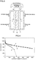
FIG. 3 is a schematic sectional view of a unit
cell of the solid polymer type fuel cell of the present
invention.
FIG. 4 is a graph which shows voltage-current
characteristics of a fuel cell.
FIG. 5 is a graph which shows voltage-current
characteristics of a fuel cell.
FIG. 6 is a graph which shows a particle size
distribution of the solid polymer electrolyte of Example 1
of the present invention.
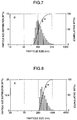
FIG. 7 is a graph which shows a particle size
distribution of the solid polymer electrolyte of Example 2
of the present invention.
FIG. 8 is a graph which shows a particle size
distribution of the solid polymer electrolyte of comparative
example.
FIG. 9 is a graph which shows a pore distribution
of carbon black.
DETAILED DESCRIPTION OF THE INVENTION
The present invention relates to a method for
manufacturing an assembly comprising a solid polymer electrolyte
membrane and electrodes provided on both sides of
the membrane, wherein at least one of the electrodes is
formed by a step of preparing a mixed liquid containing an
organic solvent, a noble metal catalyst-supporting carbon
powder and a colloid of a solid polymer electrolyte having
a particle size of 1 nm or more and less than 400 nm, said
colloid being adsorbed to the carbon powder and a step of
forming an electrode by coating said mixed liquid on one
side of a gas-diffusible layer. In more detail, as shown
in FIG. 1, the steps of manufacture of the assembly may
include a first step of preparing a dispersion by dispersing
a noble metal catalyst-supporting carbon power in an
organic solvent, a second step of obtaining a mixed liquid
by mixing this dispersion with an alcoholic solution of a
solid polymer electrolyte to produce a colloid of the
solid electrolyte having a particle size of 1 nm or more
and less than 400 nm and simultaneously adsorb the colloid
to the carbon powder, a third step of making an electrode
by coating the mixed liquid on one side of a gas-diffusible
layer, and a fourth step of pressing the electrode to
at least one side of a solid polymer electrolyte membrane
to integrally join them.
Moreover, the steps of manufacture of the assembly
may include a first step of preparing a colloidal dispersion
by mixing an organic solvent and an alcoholic
solution of a solid polymer electrolyte to produce a colloid
having a particle size of 1 nm or more and less than
400 nm, a second step of mixing said colloidal dispersion
with a noble metal catalyst-supporting carbon powder to
prepare a mixed liquid in which the colloid is adsorbed to
the carbon powder, and the above third and fourth steps.
According to the above method, the colloid of
solid polymer electrolyte having a severely adjusted particle
size can be uniformly adsorbed to carbon powder, and
therefore it becomes possible to disperse catalyst fine
particles 3, carbon fine powders 4 and solid polymer electrolyte
5 in such a state that they uniformly adhere to
each other inside the catalyst layer 2 of electrode 1 as
shown in the schematic sectional view of electrode of FIG.
2.
When thickness of the coat of the solid polymer
electrolyte is too large, diffusion route of hydrogen and
oxygen up to the catalyst surface becomes long to increase
concentration polarization of electrode reaction, and when
it is too small, transfer route of proton becomes insufficient
to cause increase of internal resistance of the
electrode. In the present invention, the thickness of the
coat can be controlled by adjusting the particle size of
colloid of the solid polymer electrolyte.
According to such construction of the catalyst
layer 2, the three channels of gas channel 7 formed by the
void between the carbon powders 4 which is a passage for
feeding a fuel gas such as hydrogen or an oxidizing agent
gas such as oxygen, proton channel 8 formed by the
hydrated solid polymer electrolyte 5, and electron channel
6 formed by mutual connection of the carbon fine powders
can be efficiently formed in close to each other inside
the same catalyst layer. In FIG. 2, 9 indicates a gas-diffusible
layer and 10 indicates a solid polymer electrolyte.
According to the present invention, feed of
hydrogen and oxygen gas and transfer of proton and electron
can be carried out simultaneously and smoothly in a
wide range by the following reaction at the hydrogen electrode:
H2 → 2H+ + 2e-
and the following reaction at the oxygen electrode:
1/2O2 + 2H+ + 2e- → H2O
Therefore, the reaction rate and the reaction area are
increased.
When colloid particle size of the polymer electrolyte
is less than 400 nm, the colloidal polymer electrolyte
layer is adsorbed widely and uniformly to the
catalyst surface, and thus a polymer electrolyte layer
superior in diffusion of hydrogen and oxygen gas can be
formed. The critical particle size for the formation of
colloid is 1 nm or more. Therefore, the colloid particle
size of the polymer electrolyte is 1 nm or more and less
than 400 nm. The carbon powders used as a carrier for
catalyst include those which are great in pore volume of
small pores of less than 10 nm, such as carbon black, and
in order to form a three-dimensional electrolyte network
in the electrode, the colloid particle size is preferably
10 nm or more. Accordingly, the colloid particle size is
more preferably 10 nm or more and less than 400 nm.
The colloid particles may be either monodisperse
or polydisperse. Average particle size of primary particles
of colloid is preferably 10 nm or more and less than
130 nm, more preferably 10 nm or more and less than 70 nm.
Since the electrolyte layer on the surface of
catalyst layer is formed with the colloid particles being
adsorbed to the catalyst surface, thickness of the electrolyte
layer usually depends on the size of primary particles
of colloid. The colloid particles may be adsorbed
in the form of multilayer, and hence the thickness is
about 1-3 times the average particle size of primary particles
of colloid. Specifically, the thickness of the
electrolyte layer is 10 nm or more and less than 400 nm,
preferably 10 nm or more and less than 200 nm, more preferably
10 nm or more and less than 50 nm.
Size of colloid can be adjusted by changing
molecular weight and molecular structure of the polymer
electrolyte, and kind and composition of organic solvents
at the step of preparation of colloid.
As the organic solvents, there may be suitably
used those having a polar group other than hydroxyl group
in the molecule and having a carbon chain of 1-8 carbon
atoms which bond to the polar group or having a dielectric
constant of 3-10 as disclosed in U.S. Pat. No.5,474,875.
U.S. Pat. No.5,474,875 is incorporated herein by reference.
Mixing ratio in weight of organic solvent and
polymer electrolyte is preferably 10 : 1 - 100 : 1, more
preferably 20 : 1 - 70 : 1, and mixing temperature is
preferably 30°C or lower, more preferably room temperature.
Furthermore, in order to enhance feeding ability
of reaction gases, carbon powders subjected to water
repelling treatment, for example, carbon powders to which
25-70% in weight ratio of a fluoropolymer is added, may be
added to the carbon powders of the present invention.
Amount of the water repelled carbon powders is 10-50% by
weight of the carbon powders supporting the noble metal
catalyst.
Examples of the present invention will be
explained referring to the accompanying drawings.
Example 1
In the first step, 50 g of carbon fine powders
supporting 10-25% by weight of a platinum catalyst were
dispersed in n-butyl acetate (CH3COOCH2(CH2)2CH3) as an
organic solvent.
In the second step, a 9% ethanolic solution of
"Flemion" manufactured by Asahi Glass Co., Ltd. as a solid
polymer electrolyte in an amount of 1 g for 60 g of n-butyl
acetate was mixed with the above dispersion to
produce a white colloid. The colloidal solid polymer electrolyte
was immediately adsorbed to the surface of the
carbon fine powders supporting the catalyst. After a while
from completion of addition of all polymer electrolyte
solution, stirring was stopped and the supernatant liquid
became transparent. When the carbon powders adsorbing the
solid polymer electrolyte were allowed to collide with
each other by an ultrasonic dispersing device, the
adsorbed polymer was also adsorbed to other carbon powders,
resulting in bridging agglomeration and the dispersion
became pasty.
In the third step, the resulting paste was
coated on a carbon paper substrate to which 20-60% by
weight of a fluoropolymer was previously added
(manufactured by Toray Industries, Inc.). The bridging
agglomeration which occurred in the second step prevented
the catalyst fine particles from penetrating into the
carbon paper and only the solvent was removed and filtered,
whereby it became possible to mold the catalyst layer on
the surface of the substrate.
In the fourth step, the above electrodes were
hot pressed on both sides of Nafion membrane manufactured
by DuPont de Nemours, E.,I. Co., by application of a pressure
of 5-100 kg/cm2 at 120-200°C to make a cell A.
Example 2
Cell B was produced in the same manner as in
Example 1, except that "5% Nafion solution" manufactured
by Aldrich Chemical Co., Ltd. was used as the solid polymer
electrolyte in the second step.
Comparative Example
Cell X was produced in the same manner as in
Example 1, except that "5% Nafion solution" manufactured
by Aldrich Chemical Co., Ltd. was used as the solid polymer
electrolyte and the mixing was carried out under heating
at 50°C in the second step.
FIG. 3 shows a schematic sectional view of a
unit cell of the manufactured solid polymer type fuel cell.
In FIG. 3, 10 indicates a solid polymer electrolyte membrane.
In the above Examples and Comparative Example,
"Nafion 112 membrane" manufactured by DuPont de
Nemours,E.I., Co. was used as the solid polymer electrolyte
membrane 10. In FIG. 3, 11 and 12 indicate a porous
negative electrode and a porous positive electrode,
respectively. The amount of the solid polymer electrolyte
added was 1.0 mg/cm2 per apparent electrode area for both
the electrodes, but the same characteristics were obtained
with addition of the electrolyte in the range of 0.1-3.0
mg/cm2. The amount of platinum was 0.5 mg/cm2 similarly
per apparent electrode area. Discharge test was conducted
by feeding hydrogen gas moisturized at 90°C to the negative
electrode side and oxygen gas moisturized at 80°C to the
positive electrode side from the inlet of the cell toward
the outlet of the cell, respectively.
FIG. 4 shows voltage-current characteristics of
the cells made in Examples 1 and 2 and Comparative Example.
Current densities of cells A and B of the present invention
and cell X of Comparative Example at 500 mV were 1200,
1150, and 360 mA/cm2, respectively. The cells of the present
invention showed characteristics of more than 3 times
that of Comparative Example. FIG. 5 shows characteristics
obtained by Tafel plotting the respective characteristics
of FIG. 4. Current densities of cells A and B of the present
invention and cell X of Comparative Example at 850 mV
were 60, 26, and 10 mA/cm2, respectively. The straight
line portion of the Tafel plotted characteristics shows
activation polarization, namely, characteristics of the
region where polarization caused by charge transport determines
the rate of reaction, and current density of this
region at a given voltage can approximate to the reaction
area of the electrode. Therefore, it was found that cell A
of Example 1 of the present invention had a reaction area
of 6 times that of cell X of Comparative Example, and cell
B had a reaction area of 2.6 times that of cell X.
FIGS. 6-8 show particle size distributions of
colloids A', B', and X' prepared by mixing the solid polymer
electrolyte used in Examples 1 and 2 and Comparative
Example with n-butyl acetate solvent, which were measured
by cumulant analysis using a dynamic light scattering
photometer DLS-7000 manufactured by Ohtsuka Denshi Co.,
Ltd. Table 1 shows average particle size, primary particle
size, range of particle size distribution and polydisperse
index of the colloid particles. A polydisperse index of
0.1 or less means monodisperse, and that of more than 0.1
means polydisperse.
| | A' | B' | X' |
| Average particle size of colloid (nm) | 102 | 154 | 514 |
| Average particle size of primary particles (nm) | 16 | 122 | 424 |
| Range of particle size distribution (nm) | 13∼340 | 73∼351 | 282∼1200 |
| Polydisperse index | 0.207 | 0.123 | 0.073 |
It was seen that colloid A' of Example 1 had a
distribution range of 13-340 nm and an average particle
size of 102 nm, and was in polydisperse state, but most of
the colloid was occupied by particles of about 16 nm. It
was seen that colloid B' of Example 2 had a distribution
range of 73-351 nm and an average particle size of 154 nm,
was in slightly polydisperse state, and had an average
particle size of primary particles of about 122 nm. On the
other hand, it was seen that colloid X' of Comparative
Example comprised particles of monodisperse state having a
distribution range of 282-1200 nm and having a primary
particle size of about 424 nm.
Since the electrolyte layer on the surface of
catalyst is formed by the adsorption of primary particles
of the above-mentioned colloid to the surface of catalyst,
the thickness of the layer depends on the primary particles
of the colloid, and besides, the primary particles
are sometimes adsorbed in the form of multilayer, and
therefore, the thickness was 1-3 times the particle size.
As a result, the thickness of the electrolyte layer was
122-366 nm in the case of B' and 16-48 nm in the case of
A'. On the other hand, it was 424 nm or more in the case
of X'.
It can be seen from the results of particle size
distribution of colloid particles of the solid polymer
electrolyte that colloids having various particle size can
be prepared by changing kind of solid polymer materials,
mixing conditions and the like by the method of the present
invention. It can be seen from the results of FIGS. 4
and 5 that state of colloid greatly affects the cell characteristics.
Cells A and B of Examples 1 and 2 in which
the particle size of colloid was distributed in the range
of 10 nm or more and less than 400 nm showed high characteristics
and the comparative cell X in which the colloid
particles had an average particle size of 400 nm or more
showed low characteristics. It is considered that in cells
A and B, the solid polymer electrolyte was adsorbed widely,
thinly and uniformly to the surface of catalyst and the
polymer electrolyte layer was formed in such a thickness
that hydrogen and oxygen gas can satisfactorily diffuse
therethrough. On the other hand, cell X had a small reaction
area and showed low characteristics in the high current
density region. It is considered that this is because
since colloid X' was large, the solid polymer electrolyte
layer could not be uniformly adsorbed to the surface of
catalyst to reduce the reaction area and since thickness
of the adsorbed polymer electrolyte layer was great, diffusion
route of hydrogen and oxygen was long, resulting in
increase of concentration overvoltage to cause deterioration
of characteristics in the high current density region.
That is, it is considered that an optimum polymer electrolyte
layer can be formed by the present invention.
FIG. 9 shows results of pore distribution of
typical carbon blacks used as a carrier for catalyst which
were obtained by nitrogen gas adsorption method. Ketjen
Black 600D (KB600JD) and Ketjen Black EC (KBEC) manufactured
by Lion Co., Ltd. and acetylene blacks (AB, AB1, AB2,
AB3, and AB18) manufactured by Denki Kagaku Kogyo Co., Ltd.
were used as the carbon blacks. It can be seen from FIG. 9
that these carbon blacks have a large volume for the pores
of 10 nm or less. Since primary particle size of carbon
black is 10 nm or more, these pores can be considered to
be those formed on the surface of carbon black particles.
Therefore, it is preferred for forming a three-dimensional
electrolyte network in the electrode that thickness of the
solid polymer electrolyte layer formed on these carbon
blacks is 10 nm or more.
The kind and amount of the above-mentioned
organic solvents can be experimentally optionally selected
so that particle size of the colloid is in the range of 1
nm or more and less than 400 nm. The Examples of the present
invention describe the representative values and do
not restrict the present invention.
Moreover, in the above Examples, solutions of
Flemion and Nafion were used as representative examples of
polymers comprising a copolymer of tetrafluoroethylene and
perfluorovinyl ether as the solid polymer electrolyte, but
the polymers are not limited to these examples as far as
they are polymer electrolyte having proton exchange group,
and the similar effects were obtained by using polymers of
different molecular structures. For example, there may be
used perfluorovinyl ethers, polymers of different side
chain molecular length, polymers comprising a copolymer of
styrene and vinyl benzene, and other hydrocarbon polymer
electrolytes.
Furthermore, in the above Examples, a hydrogen-oxygen
fuel cell was taken up, but the present invention
can also be applied to fuel cells which use modified
hydrogen obtained from methanol, natural gases, naphtha,
etc., fuel cells which use air as oxidizing agent, and
liquid fuel cells which directly use methanol as a fuel.
Moreover, in the above Examples, fuel cells were
constructed using an assembly of a solid polymer electrolyte
and an electrode, but the assembly can be effectively
applied to generators or purifiers of oxygen, ozone,
hydrogen, etc. and various gas sensors such as oxygen sensor
and alcohol sensor.
As explained above, according to the present
invention, contact between the solid polymer electrolyte
and the catalyst in the electrode and dispersing state of
them in the electrode can be improved, and the three channels
of the gas channel formed by the voids between fine
carbon powders which is a channel for feeding fuel gases
such as hydrogen and oxidizing agent gases such as oxygen,
the proton channel formed by the hydrous solid polymer
electrolyte and the electron channel formed by mutual connection
of carbon fine powders are formed very close to
each other in the same catalyst layer, and the reaction
area is increased.
Therefore, feeding of hydrogen and oxygen gas
and transfer of proton and electron are carried out
smoothly and in a wide range, and thus the present invention
can provide solid polymer type fuel cells which exhibit
higher discharge performance.