Background of the Invention
This invention relates to an inlet for a water heater, which inlet serves to reduce
the generation of temperature gradients within the water heater. It is preferably
connected into the water beater tank through the top or a side wall.
Field of the Invention
The generation of temperature gradients in water heaters above the desired outlet
temperature represents a serious problem. Heating of water promotes the precipitation
of sediment, and excessive temperature gradients tend to accelerate sediment precipitation.
Accumulated sediment tends to harden, forming a scale on various tank surfaces, which
reduces water beater efficiency and, in many cases, can lead to failure.
Also, excessive temperature gradients tend to cause excessive temperature
fluctuations. Such fluctuations bring about undue fatigue of the water heater tank and can
reduce water heater longevity.
Furthermore, excessive temperature gradients within the water heater's tank can
tend to reduce the draw-off ability of the water heater and can decrease the water heater's
response time. Both of these conditions compromise water heater efficiency.
Objects of the Invention
It is an object of the invention to provide an inlet adapted to reduce the generation
of temperature gradients that tend to develop in water heater tanks.
It is another object of the invention to provide an inlet adapted to increase water
heater efficiency.
It is yet another object of the invention to provide a cost effective inlet that is easy
to install at the top or side of a water heater.
Other objects of the invention will become clear from the drawings and
descriptions that follow.
Brief Description of the Drawings
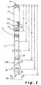
Fig. 1 is a side view of an embodiment of a top inlet according to this invention.
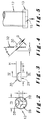
Fig. 2 is an end view of the top inlet shown in Fig. 1.
Fig. 3 is a side view of a portion of the top inlet shown in Fig. 1.
Fig. 4 is a cross-sectional side view of a detail of the top inlet shown in Fig. 3.
Fig. 5 is a side view of another embodiment of a top inlet according to this
invention.
Fig. 6 is a side view of an embodiment of a water heater comprising the top inlet
shown in Fig. 1 or Fig. 5.
Fig. 7 is a side view of an embodiment of a side inlet according to this invention.
Fig. 8 is a front end view of a portion of the side inlet shown in Fig. 7.
Fig. 9 is a rear end view of a portion of the side inlet shown in Fig. 7.
Fig. 10 is a rear end view of another portion of the side inlet shown in Fig. 7.
Fig. 11 is a cross-sectional side view of a detail of the side inlet shown in Fig. 9.
Fig. 12 is a side view of an embodiment of a water heater comprising the side inlet
shown in Fig. 7.
Summary of the Invention
This invention relates to an inlet adapted for delivering water into a water heater
tank through a top port. The inlet includes a conduit having a proximal portion with a
flow opening for water flow into the inlet from a water source. The conduit extends from
the proximal portion downwardly to a distal end portion, which includes a flow opening
for water flow from the conduit into the tank. The conduit defines a longitudinal flow
passage. A plurality of wall openings is provided for radial flow from the flow passage.
Means such as a deflector is provided within the conduit adjacent to each of the wall
openings. They extend into the flow passage for deflecting at least a portion of the water
flow radially outwardly through the wall openings.
Upon installation of the inlet into the water heater tank, the proximal portion of
the conduit extends through the tank's top port and the distal end portion extends
downward toward a bottom surface of the tank. As water flows into the tank, the wall
openings and the deflecting means co-act to reduce the generation of temperature
gradients in the tank.
This invention also relates to a water heater that is capable of reducing the
generation of such temperature gradients. It includes an inlet conduit, as described, as
well as a fitting for engaging the inlet conduit to the tank's top port.
Another embodiment relates to an inlet delivering water into a water heater tank
through a side port. The inlet includes a conduit having a proximal portion with a flow
opening for water flow into the inlet from a water source. The conduit also includes an
intermediate portion that extends from the proximal portion to a distal portion, which
includes a flow opening for water flow from the conduit into the tank. The proximal,
intermediate and distal portions together define a flow passage. Means such as a
deflector is provided within the distal portion of the conduit. It extends into the flow
passage for deflecting the water flow.
Upon installation of the inlet into the water heater tank, the proximal portion of
the conduit extends through the tank's side port, the intermediate portion extends toward
an interior region of the tank and the distal portion extends downward toward a bottom
of the tank. As water flows into the tank, the distal portion of the conduit and the
deflecting means co-act to reduce the generation of temperature gradients in the tank.
This invention also relates to a water heater that is adapted to reduce the generation
of such temperature gradients. It includes an inlet conduit, as described, as well as a
fitting for engaging the inlet conduit to the tank's side port. The water heater is capable
of reduced temperature gradients in accordance with an object of this invention.
Detailed Description of the Invention
The following description is intended to refer to specific embodiments of the
invention illustrated in the drawings. While a specific configuration has been selected for
illustration, the flow pattern of incoming water is highly effective with various
modifications. This description is not intended to define or limit the scope of the
invention, which is defined separately in the claims that follow. Also, it will be
appreciated that the drawings are not necessarily to scale and are merely provided for the
purpose of illustration.
Generally speaking, the invention relates to an inlet adapted for delivering cold
water into the storage tank of a water heater. Although the invention has been discovered
to be highly beneficial for use in gas-fired water heaters that are intended for commercial
use, the inlet is highly effective in electric, oil-fired and any other type of residential or
commercial water heater.
The inlet includes a conduit that is sized and shaped to be installed through the top
port of a water heater. It has a proximal portion that is to be connected to the tank's top
port by means of a fitting. Extending from the proximal portion is a distal portion that
terminates at a flow opening for introducing water from the conduit and into the tank's
interior.
Upon installation of the inlet into the water heater's tank, the proximal portion of
the inlet conduit preferably extends through the tank's top port. The conduit extends
downwardly from the proximal portion, preferably along a vertical axis. The distal
portion preferably extends downwardly toward a bottom of the tank and terminates at an
end opening that is most preferably positioned adjacent to the tank's bottom surface.
The inlet conduit is preferably provided with a substantially tubular shape with a
substantially constant cross-sectional area for the flow passage that extends through the
proximal and distal portions. The flow opening is optionally reduced or constricted. The
preferred inlet conduit defines a substantially continuous flow passageway extending from
a proximal end outside the tank to a distal end oriented toward the tank's bottom.
A plurality of wall openings are provided in the wall of the conduit at locations
between the proximal and distal ends of the conduit, preferably closer to the distal end.
The wall openings provide passages for flow from the longitudinal flow passageway in
the conduit radially outwardly into the tank's interior.
A means, such as one or more flow deflectors or an equivalent structure, is
connected within the inlet conduit adjacent to each of the wall openings. The means is
positioned to extend into the water flow path in order to deflect the water flow as it
travels through the inlet conduit radially outwardly through an adjacent wall opening
toward the tank's interior. In a preferred embodiment, the means for deflecting the water
flow includes an angled surface positioned adjacent to the conduit's wall and extending
within the conduit into the water flow path. The means can be any deflector or element
that redirects the water flow as it passes through the conduit toward the tank's interior.
Most preferably, it takes the form of a tab that is connected in the conduit's wall and that
extends toward the central axis of the conduit. Such a preferred tab is located adjacent
to a hole in the conduit's wall, perhaps a hole created by forming the tab. Most
preferably such a tab is positioned just downstream from the wall opening. Although the
means for deflecting the water flow is preferably integral with the inlet conduit or the
wall thereof, it can be formed from a separate component that is attached to the conduit
by a fastener, snap-in or press-fit engagement, weld, threads, or any other known or
equivalent fastening means.
A threaded fitting is preferably used to connect the inlet conduit to the tank's top
port. In a preferred embodiment, a threaded fitting is engaged over the proximal portion
of the inlet conduit so that it can be threaded into a spud attached to the water heater
tank's top. The fitting is preferably engaged to the inlet conduit so that longitudinal
movement of the inlet conduit through the fitting is prevented. In a preferred structure,
this is accomplished by forming a ring-type groove in the outer surface of the fitting in
order to create a radially inwardly extending surface within the fitting that can capture
the conduit. It is this ring groove that prevents such longitudinal movement.
Although the deflecting means and wall openings are preferably positioned along
the conduit so that the orientation of the conduit about its longitudinal axis is not critical
for optimal performance, the ring groove can be adapted to permit rotation of the inlet
conduit even after the inlet is installed in the water heater. Accordingly, a means is
preferably provided for rotating the conduit in the fitting to adjust the conduit's
orientation. The means may include a recess, such as a slot for example, or any surface
positioned near or at the proximal end of the conduit. Engagement of such a surface
facilitates the conduit's rotation after the fitting is threaded into the spud. A visual
indicator is preferably provided to indicate the orientation of the conduit from outside of
the tank.
In an optional feature of the invention, the proximal end of the inlet conduit
extends outwardly beyond the proximal end of the fitting. This feature provides
unobstructed access to the proximal end of the conduit for rotational adjustment. Also,
when a source of cold water is connected to the proximal end of the fitting to make the
necessary connection, the proximal end of the inlet conduit can extend outwardly beyond
the end of the fitting. It has been discovered that water flow from the source into the
inlet is directed toward the central interior region of the inlet. Such flow reduces the
wear and erosion that can otherwise be caused when flowing water directly impacts
against the fitting. Instead, a buffer of slow-moving water is trapped adjacent to the
fitting's end. Such an optional feature may be especially desirable when dielectric
insulation is positioned between the fitting and the conduit. The optional extension of the
conduit beyond the fitting's end prevents accelerated erosion of the dielectric insulation.
The invention further relates to an inlet adapted for delivering cold water through
a side port. Although the invention has been discovered to be highly beneficial for use
in gas-fired water heaters that are intended for commercial use, the inlet is highly
effective in electric, oil-fired and any other residential or commercial water heaters.
The inlet has a proximal portion that is to be connected to the tank's side port by
means of a fitting. Extending from the proximal portion is an intermediate portion that
is intended to be positioned within the tank so that it extends from the side port and
preferably toward a central region of the tank's interior, most preferably toward the
central, vertical axis of the water heater. From the end of the intermediate portion
extends a distal portion that terminates at a flow opening for introducing water from the
conduit and into the tank's interior.
Upon installation of the inlet into the water heater's tank, the proximal portion of
the inlet conduit preferably extends through the tank's side port. The intermediate portion
preferably extends toward the tank's interior. Most preferably, the intermediate portion
is horizontal or near horizontal so that it extends toward the tank's interior in a plane that
is substantially parallel to the tank's bottom. The distal portion preferably extends
downwardly toward a bottom of the tank. From the downstream end of the intermediate
portion, the conduit's distal portion most preferably curves downwardly toward the tank's
bottom surface. Such curvature is preferably gradual so that the conduit can easily be
formed by a bending process, if desired.
The flow opening through which water flows from the inlet is positioned at the
downstream end of the distal portion. The opening is preferably oriented at some angle
to the axis of the distal portion. In other words, the flow opening preferably lies in a
plane that is at an angle to the distal portion's axis; most preferably an acute angle such
that the opening generally faces the central region of the tank's interior.
The inlet conduit is preferably provided with a substantially tubular shape with a
substantially constant cross-sectional area for the flow passage that extends through the
proximal, intermediate and distal portions and through the flow opening. The preferred
inlet conduit defines a substantially continuous flow passageway extending from a
proximal end outside the tank to a distal end oriented toward the tank's bottom central
region.
A means, such as one or more flow deflectors or an equivalent structure, is
connected adjacent to and within the distal portion of the inlet conduit and is positioned
to extend into the water flow path in order to deflect the water flow as it travels through
the inlet conduit toward the tank's interior. In a preferred embodiment, the means for
deflecting the water flow includes an angled surface positioned adjacent to the distal
portion's wall and extending within the distal portion into the water flow path. The
means can be any deflector or element that redirects or disturbs the water flow as it
passes through the distal portion toward the tank's interior. Most preferably, it takes the
form of a tab that is connected in the distal portion's wall and that extends toward the
central axis of the conduit. Although such a preferred tab may be located adjacent to a
hole in the distal portion's wall, perhaps a hole created by forming the tab, it is not
necessary for such a hole to exist and the conduit's end opening may be the only opening.
Also, although the means for deflecting the water flow is preferably integral with the inlet
conduit or the wall thereof, it can be formed from a separate component that is attached
to the distal portion by a fastener, snap-in or press-fit engagement, weld, threads, or any
other known or equivalent fastening means.
A threaded fitting is preferably used to connect the inlet conduit to the tank's side
port. In a preferred embodiment, a threaded fitting is engaged over the proximal portion
of the inlet conduit so that it can be threaded into a spud attached to the water heater
tank's wall. The fitting is preferably engaged to the inlet conduit so that longitudinal
movement of the inlet conduit through the fitting is prevented although rotational
movement of the inlet conduit about the conduit's axis is permitted. In a preferred
structure, this is accomplished by forming a ring-type groove in the outer surface of the
fitting in order to create a radially inwardly extending surface within the fitting that can
capture the conduit. It is this ring groove that prevents such longitudinal movement while
permitting rotational movement.
Such rotational movement of the conduit in the fitting confers a significant benefit
because the downward orientation of the conduit's distal portion should be maintained for
optimal performance of the inlet and because this orientation will change as the fitting is
threaded into the tank. Accordingly, a means is preferably provided for rotating the
conduit in the fitting to adjust the orientation of the distal portion. The means may
include a recess, such as a slot for example, or any surface positioned near or at the
proximal end of the conduit. Engagement of such a surface facilitates the conduit's
rotation after the fitting is threaded into the spud. A visual indicator is preferably
provided to indicate the orientation of the conduit from outside of the tank.
In another preferred feature of the invention, the proximal end of the inlet conduit
extends outwardly beyond the proximal end of the fitting. This preferred feature provides
unobstructed access to the proximal end of the conduit for rotational adjustment. Also,
when a source of cold water is connected to the proximal end of the fitting to make the
necessary connection, the proximal end of the inlet conduit extends outwardly beyond the
end of the fitting. It has been discovered that water flow from the source into the inlet
is directed toward the central interior region of the inlet. Such flow reduces the wear and
erosion that can otherwise be caused when flowing water directly impacts against the
fitting. Instead, a buffer of slow-moving water is trapped adjacent to the fitting's end.
Such a preferred feature is especially desirable when dielectric insulation is positioned
between the fitting and the conduit. The preferred extension of the conduit beyond the
fitting's end prevents accelerated erosion of the dielectric insulation.
Referring to Figs. 1-4, a preferred embodiment of an inlet according to this
invention, designated by the numeral "10", will now be described. Fig. 1 shows a side
view of inlet 10 having an inlet conduit 12 with a proximal portion 12A and a distal
portion 12B that extends to the end of the inlet conduit. Together, portions 12A and 12B
define a continuous flow passageway with a tubular cross-section, although other cross-sections
are contemplated as well. In this embodiment, portions 12A and 12B share the
same axis, and portion 12B is substantially an extension of portion 12A. The inlet
conduit can be formed from plastic or metal, as desired.
Engaging the proximal portion 12A of the conduit is a fitting 14 that is preferably
formed from a metal such as steel. Fitting 14 includes male pipe threads 16 and 18 at
each end. Pipe thread 16 is used for water-tight connection to a source of cold inlet
water (not shown). Pipe thread 18 is intended for threaded engagement of fitting 14 into
the spud of a water heater's storage tank (not shown in Fig. 1). Within fitting 14, and
captured between fitting 14 and the inlet conduit, is a dielectric insulator 20, preferably
in the form of an insulating polymeric tube. Dielectric insulator 20 provides dielectric
isolation between the metallic fitting 14 and the inlet conduit.
A ring-type groove 22 is formed in the outer surface of fitting 14 by known
manufacturing methods. The groove 22 provides the interior surface of fitting 14 with
a radially inwardly extending surface that captures dielectric insulator 20 as well as
proximal portion 12A of the inlet conduit. A ring groove is preferably used to serve this
purpose because it prevents longitudinal movement of the inlet conduit through fitting 14,
along its axis. At the same time, groove 22 can be adapted to permit rotational
movement of the inlet conduit with respect to the fitting 14 so that their relative positions
can be adjusted, if desired. A proximal end 24 of the inlet conduit optionally extends
outwardly beyond the proximal end of the fitting 14 in the preferred embodiment for the
reasons set forth in the general description of the invention. Although not shown, the
proximal end of the inlet conduit preferably includes a pair of slots, or some other
equivalent recess or surface, in order to facilitate rotation of the conduit within the fitting
14. A tool can be positioned across such slots and rotated until a desired position is
obtained, if necessary. The slots themselves, or a separate indicator such as an arrow or
other indicia, can act to signify the orientation of the conduit with respect to the fitting
and tank.
At the other end of the inlet conduit, an opening 26 is provided at the downstream
end of distal portion 12B. In this preferred embodiment, opening 26 occupies a plane
that is substantially horizontal and normal to the longitudinal axis of portions 12A and
12B. The opening 26 extends entirely across the distal portion 12B and, when viewed
from the bottom (Fig. 2), it has a cross-sectional area as large as the cross-sectional area
of the flow passageway through the inlet conduit.
One possible form of a deflector or deflecting means is designated with the
numeral "28", although many other possible forms and configurations are contemplated.
In this embodiment, a plurality of deflectors or tabs 28 are integrally connected to the
interior surface along distal portion 12B of the inlet conduit. Tabs 28 extend inwardly
toward the central region of the flow passageway in order to deflect the water flow
through adjacent wall openings 30 that are located just upstream of corresponding
deflectors. The tabs 28 cooperate with the inlet conduit to reduce the generation of
temperature gradients within the water heater.
Further details of a preferred tab 28 will now be described with reference to Figs.
2, 3 and 4. Tab 28, in this embodiment, takes the form of an integral, semi-circular tab
that is cut into the wall of the inlet conduit and bent along a fold line 29 (Fig. 3) in a
direction toward the conduit's central axis. In so doing, the corresponding opening 30
is created in the conduit's wall adjacent to and upstream of tab 28. It is important to note
that tab 28 can be formed in a wide variety of manners. In fact, deflector 28 can be
formed as an entirely separate component that can be attached to, or mounted within, the
distal portion 12B of the inlet conduit.
As shown in Fig. 4, which provides a cross-sectional view of a portion of a wall
32 in the distal portion 12B, the tab 28 extends into the flow path at an angle such as
angle "α". The distance it extends into the flow path is designated by the letter "D" in
Fig. 4, and the size of the gap or opening 30 adjacent to the tab 28 is indicated by the
letter "G". Angle α is preferably an acute angle in order to best deflect the water flow
out through the wall openings.
Although only one deflector means arrangement is illustrated in the embodiment
shown in the Figures, it is of course contemplated that a wide variety of arrangements can
be used and that deflecting means can be positioned in a variety of locations and
orientations.
Referring again to Fig. 1, the preferred embodiment of inlet 10 includes a series
of tabs 28 positioned in four planes separated along the length of distal portion 12B.
Three tabs 28 are preferably provided in each of the four planes. Referring to Fig. 2,
deflectors 28 extend inwardly and upwardly toward the central axis of the longitudinal
flow passageway. In this embodiment, tabs 28 extend inwardly from the wall 32 of inlet
conduit 12 from its inside diameter ID. Shown in dotted lines is a central region C of
unobstructed flow through the plane of tabs 28. Central region C can vary in diameter
from zero or near zero to a diameter corresponding to the inside diameter of the inlet.
However, central region C is preferably limited in diameter so that significant flow is
directed through the wall openings. Most preferably, the cross-section area of central
region C is substantially less than the cross-sectional area of inside diameter ID. For
example, each tab 28 most preferably blocks between about 10% and 50% of the flow
path, although smaller and larger tabs are contemplated as well.
In operation, as water flows downwardly through the flow passageway, a portion
of the water flow impinges against tabs 28 and is swept radially outwardly in the general
direction indicated by the arrows in Figs. 1 and 4. The rest of the water flow that
remains in the flow passageway exits inlet conduit 12 through end opening 26 toward the
bottom of the tank. Accordingly, water flows out through each of the wall openings 30
(by action of the adjacent tabs 28) and through end opening 26. This preferred flow
pattern is capable of reducing the generation of temperature gradients within the water
heater's tank.
Referring now to Fig. 3, each tab 28 has a width W and a height H, which also
corresponds to the dimensions of the adjacent wall opening 30 in this embodiment.
Together, width W and height H define the surface area of the deflector, which can be
adjusted depending on factors such as the number of deflectors used, the relative position
of the deflectors, the inside diameter ID of the inlet conduit 12 (Fig. 2), the capacity and
diameter of the water heater's tank, and the position of the deflector along the length of
inlet conduit 12.
Inlet conduit 12 is especially well adapted for use in commercial water heaters and,
accordingly, may have an inside diameter as large as about 1¼" or larger. For this
reason, tabs 28 should be large enough to "pull" or redirect a significant portion of the
water flow out from the flow passageway. In order to encourage such flow, inlet 12 is
optionally provided with a constriction such as the plug 13 shown in Fig. 5 in order to
form a reduced flow opening 15 for flow into the tank. Such a reduced opening increases
the pressure in the inlet conduit 12 to encourage maximum flow through tabs 28.
Referring now to Fig. 6, a portion of a water heater 40 is illustrated with an inlet
according to this invention as a component thereof. Water heater 40 includes an inlet
spud 42 with female pipe threads (not shown) positioned on a top surface 41. Male pipe
threads 18 of fitting 14 are threaded into spud 42 in the usual manner until inlet 10 is
sealingly engaged to the water heater 40. In order to install inlet 10, a pipe wrench or
other tool can be used to rotate fitting 14 with respect to spud 42 to engage the threads.
When the desired water-tight seal is created between the fitting and the spud, the
orientation of the inlet conduit can then be adjusted (if necessary). Thereafter, the source
of cold inlet water (not shown) can be connected to the male threads 16 on the proximal
end portion of fitting 14. The inlet is then ready for use in operation.
Referring to Figs. 7-11, a preferred embodiment of an inlet according to this
invention, designated by the numeral "10", will now be described. Fig. 7 shows a side
view of inlet 10 having an inlet conduit with a proximal portion 12A, an intermediate
portion 12B extending from the downstream end of the proximal portion, and a distal
portion 12C that extends from the downstream end of the intermediate portion 12B to the
end of the inlet conduit. Together, portions 12A, 12B and 12C define a continuous flow
passageway with a tubular cross-section, although other cross-sections are contemplated
as well. In this embodiment, portions 12A and 12B share the same axis, and portion 12B
is substantially an extension of portion 12A. The axis of portion 12C curves downwardly
from that of portions 12A and 12B. The inlet conduit can be formed from plastic or
metal, as desired.
Engaging the proximal portion 12A of the conduit is a fitting 14 that is preferably
formed from a metal such as steel. Fitting 14 includes male pipe threads 16 and 18 at
each end. Pipe thread 16 is used for water-tight connection to a source of cold inlet
water (not shown). Pipe thread 18 is intended for threaded engagement of fitting 14 into
the spud of a water heater's storage tank (not shown in Fig. 7). Within fitting 14, and
captured between fitting 14 and the inlet conduit, is a dielectric insulator 20, preferably
in the form of an insulating polymeric tube. Dielectric insulator 20 provides dielectric
isolation between the metallic fitting 14 and the inlet conduit.
A ring-type groove 22 is formed in the outer surface of fitting 14 by known
manufacturing methods. The groove 22 provides the interior surface of fitting 14 with
a radially inwardly extending surface that captures dielectric insulator 20 as well as
proximal portion 12A of the inlet conduit. A ring groove is preferably used to serve this
purpose because it prevents longitudinal movement of the inlet conduit through fitting 14,
along its axis. At the same time, groove 22 permits rotational movement of the inlet
conduit with respect to the fitting 14 so that their relative positions can be adjusted. A
proximal end 24 of the inlet conduit extends outwardly beyond the proximal end of the
fitting 14 in the preferred embodiment for the reasons set forth in the general description
of the invention.
At the other end of the inlet conduit, an opening 26 is provided at the downstream
end of distal portion 12C. In this preferred embodiment, opening 26 occupies a plane
that is substantially vertical and normal to the axis of portions 12A and 12B. It is most
preferably oriented at an acute angle with respect to the axis of distal portion 12C. The
opening 26 extends entirely across the distal portion 12C and, when viewed from the left
in Fig. 7, it has a cross-sectional area at least as large as the cross-sectional area of the
flow passageway through the inlet conduit.
One possible form of a deflector or deflecting means is designated with the
numeral "28", although many other possible forms and configurations are contemplated.
In this embodiment, deflector 28 is integrally connected to the interior, lower surface of
distal portion 12C of the inlet conduit. Deflector 28 extends inwardly toward the central
region of the flow passageway in order to deflect the water flow and to cooperate with
the inlet conduit to reduce the generation of temperature gradients within the water
heater.
Further details of preferred deflector 28 will now be described with reference to
Figs. 8, 9 and 11. Deflector 28, in this embodiment, takes the form of an integral semi-circular
tab that is cut into the wall of the inlet conduit and bent along a fold line 29
toward the conduit's central axis. In so doing, an opening 30 is created in the conduit's
wall adjacent to and downstream of deflector 28. Although such an opening may be
preferred, it is important to note that deflector 28 can be formed in a wide variety of
manners both with and without the formation of a hole in the conduit's wall. In fact,
deflector 28 can be formed as an entirely separate component that can be attached to, or
mounted within, the distal portion 12C of the inlet conduit.
As shown in Fig. 11, which provides a cross-sectional view of a portion of a wall
34 in the distal portion 12C, the deflector 28 extends at an angle such as angle "α" a
predetermined distance into the flow path defined by the inlet conduit. This distance is
designated by the letter "D" in Fig. 11, and the size of the gap or opening 30 adjacent
to the deflector 28 is indicated by the letter "G". Although only one deflector means is
illustrated in the embodiment shown in the Figures, it is of course contemplated that more
than one deflector can be used and that they can be positioned in a variety of locations
and orientations.
Fig. 10 illustrates a preferred embodiment of the proximal end of the inlet conduit.
It preferably includes a pair of slots 32, or some other equivalent recess or surface, in
order to facilitate rotation of the conduit within the fitting 14. In this embodiment, a tool
can be positioned across slots 32 and rotated until the distal portion 12C of the inlet
conduit is facing in the optimal direction, which is toward a bottom region of the water
heater tank. The slots 32 themselves, or a separate indicator such as an arrow or other
indicia, act to signify the orientation of the conduit with respect to the fitting and tank.
Referring now to Fig. 12, a portion of a water heater 40 is illustrated with an inlet
according to this invention as a component thereof. Water heater 40 includes an inlet
spud 42 with female pipe threads (not shown). Male pipe threads 18 of fitting 14 are
threaded into spud 42 in the usual manner until inlet 10 is sealingly engaged to the water
heater 40. In order to install inlet 10, a pipe wrench or other tool can be used to rotate
fitting 14 with respect to spud 42 to engage the threads. When the desired water-tight
seal is created between the fitting and the spud, the orientation of the inlet conduit can
then be adjusted utilizing the slots 32 shown in Fig. 10 so that distal portion 12C is
directed toward the tank's bottom. Thereafter, the source of cold inlet water (not shown)
can be connected to the male threads 16 on the proximal end portion of fitting 14. The
inlet is then ready for use in operation.
The following Examples illustrate significant benefits according to this invention.
The Examples are provided for illustrative purposes only, and they are not intended to
limit the invention in any way.
EXAMPLE 1
An inlet such as the one illustrated in Fig. 1 was constructed and tested in
commercial water heaters heated by gas-fired burners. The inlet was tested in
comparison to a conventional top inlet that comprised a dip tube connected to the tank
spud. The relative inlet performances were measured in relation to so-called "stacking"
or "build-up". The stacking effect is described in U.S. Patent No. 5,341,770,
incorporated herein.
In this test, each water heater was allowed to heat up to a predetermined storage
tank temperature of 180°F. Immediately after the main burner turned off, water was
drawn off at a rate of 5 gallons per minute. The draw continued until the heater's
thermostat called for heat (the main burner turned on). This cycle was repeated
continuously until the measured outlet water temperature did not vary by more than 1°F
for three consecutive draws. The test results are summarized in the following Table 1.
| Water Heater Capacity (gallons) | Input (BTUs) | Max Temp. (°F) (conventional inlet) | Temp. Gradient above 180°F (°F) (conventional inlet) | Max. Temp. (°F) (Fig. 1 inlet) | Temp. Gradient above 180°F (°F) (Fig. 1 inlet) | Decrease in Temp. Gradient (%) |
| 100 | 88,000 | 200 | 20 | 196 | 16 | 20 |
| 100 | 250,000 | 206 | 26 | 198 | 18 | 31 |
| 80 | 250,000 | 204 | 24 | 194 | 14 | 42 |
The tests revealed that the temperature gradient resulting from stacking was
reduced by replacing a conventional top inlet with the inlet embodiment shown in Fig.
1. The temperature gradient above the 180°F starting point was reduced by as much as
42%. Such reduced temperature stratification is expected to reduce lime precipitation,
lengthen the life of the water heater, and reduce or even eliminate the need for periodic
cleaning to remove precipitated sediment.
EXAMPLE 2
An inlet such as the one illustrated in Fig. 1 was tested in commercial storage-type
water heaters. The inlet was tested in comparison to a conventional top inlet, as in
Example 1, to measure relative inlet performance in relation to so-called "draw-off
ability", which is the ability of the storage water heater to deliver as much water as
possible before the water's outlet temperature drops below a predetermined temperature.
In this test, each storage water heater was allowed to heat up to a predetermined
storage tank temperature of 180°F. Once the burners turned off, they were disconnected
from the water heater's thermostat. Water was then drawn off at a rate of about 5
gallons per minute and the temperature of the outlet water was measured along with its
volume. The draw was continued until the outlet temperature dropped to about 150°F.
The test results are summarized in the following Table 2.
| Storage Water Heater Capacity (gallons) | Input (BTUs) | Drawn-off Volume (gallons) (conventional inlet) | Drawn-off Volume (gallons) (Fig. 1 inlet) | Volumetric Increase (%) |
| 75 | 160,000 | 63 | 65 | 3 |
| 80 | 250,000 | 64 | 66 | 3 |
| 100 | 250,000 | 108 | 112 | 4 |
| 100 | 300,000 | 69 | 76 | 10 |
The tests revealed that the drawn-off volume before reaching 150°F was increased
by replacing a conventional top inlet with the inlet embodiment shown in Fig. 1. The
drawn-off volume was increased by as much as 7 gallons (10%). Accordingly, more hot
water is available during a draw and hot water is available for a longer period of time.
Also, the increase in the drawn-off volume is expected to reduce temperature spikes at
the delivery point and reduce the amount of work required for any external equipment
such as booster water heaters.
EXAMPLE 3
An inlet such as the one illustrated in Fig. 1 was further tested in commercial
water heaters in relation to so-called "burner on time". The amount of elapsed time was
measured between burner shut-off and actuation of the thermostat to call for heat. The
test was similar to the test described in Example 2 except, instead of measuring the water
temperature, the time until the thermostat calls for heat was measured. The results of this
test are summarized in Table 3.
| Water Heater Storage Capacity (gallons) | Input (BTUs) | Elapsed Time (seconds) (conventional inlet) | Elapsed Time (seconds) (Fig. 1 inlet) | Time Increase (%) |
| 80 | 250,000 | 124 | 128 | 3 |
| 100 | 250,000 | 127 | 129 | 2 |
| 100 | 300,000 | 185 | 215 | 16 |
| 100 | 88,000 | 174 | 187 | 7 |
This test revealed that the amount of time in between the point when the burners
are turned off and the point when the thermostat later calls for heat was significantly
increased by replacing a conventional top inlet with the inlet embodiment shown in Fig.
1. The time was increased by as much as 30 seconds (16%), which is expected to reduce
thermostat cycling and tank fatigue.
The exact reason for these significant benefits is not certain. Nevertheless, it is
speculated that the openings in the wall of the inlet conduit, together with the utilization
of means for deflecting the water flow path through the openings, creates an extremely
beneficial flow pattern. In the preferred configuration, it creates a number of streams that
are directed out to the side of the conduit and downwardly at an angle as the water enters
the interior of the tank. It is believed that such a flow pattern creates a thermal balance
within the storage tank and enables a more rapid equilibrium between any stratified
layers. Accordingly, the water temperature differential from side-to-side and from top-to-bottom
within the tank is lower as compared to results from traditional open end or closed
end inlet supply tubes. It is also speculated that the wall openings and deflecting means
tend to distribute turbulent flow that may exist in the conduit into the tank while creating
a vertical circular flow pattern. With such a pattern, the inlet encourages water
circulation throughout the water heater's tank and reduces the temperature gradients that
tend to be generated in such tanks.
Also, when used with a burner-heated system with higher input and perhaps
multiple flue tubes, the inlet according to this invention reduces short cycling of the
burner and causes it to fire for a longer period of time. This has been discovered to
enable better polarization for the cathode, reduce the amount of stress at the weld between
the flue(s) and the base, and reduce carbonate precipitation as a result of better thermal
balance.
Many modifications to the disclosed embodiments are contemplated. For example,
although the top inlet according to this invention confers many benefits when used in a
gas-fired commercial water heater, it can be used in any residential water heater as well,
heated by any available heat source. Also, the optional end constriction embodiment
illustrated in Fig. 5 can be removed entirely or replaced with an alternative construction
such as a plug that extends into the conduit, an inwardly bent wall portion of the conduit
itself, a twisted end portion of the conduit that defines a constricted outlet diameter, or
a welded or otherwise attached component that extends the conduit and positions the
constricted opening adjacent to the conduits distal end. In some circumstances it may
even prove desirable to entirely close the conduit's end opening in order to direct all of
the water flow radially outwardly through the wall openings.
The size and shape of the deflecting means, as well as their number, can vary
widely. Although the shape illustrated in the Figures is preferred, it is believed that the
surface area and angle of the preferred deflectors may be at least as effective as their
shape. For example, a tab or deflector of small width W and large height H can be
exchanged with a deflector of large width W and small height H. Also, a semicircular
deflector with a particular surface area can be exchanged with a deflector having a
different shape but a similar surface area, although surface area can be changed as well
to suit a particular application. It is also contemplated that the preferred deflectors on the
same conduit may differ from one another in terms of their size and/or shape.
The number of preferred deflectors that are positioned in the same plane can vary
from a single deflector to 3 or 4 or more, limited only by the diameter and strength of
the inlet conduit. The distance between adjacent planes may vary or remain constant if
more than two planes of deflecting means are used. Also, the preferred deflectors can
be provided in linear rows along the length of the inlet conduit as shown in Fig. 1, for
example, or they can be staggered or helically arranged along the conduit's length.
While deflectors such as tab 28 are a preferred form of deflecting means, any structure
can be alternatively used so long as it is capable of deflecting water flow outwardly
through openings in the inlet conduit.
EXAMPLE 4
An inlet such as the one illustrated in Fig. 7 was constructed and tested in
commercial water heaters heated by gas-fired burners. The inlet was tested in
comparison to a conventional side inlet that comprised a nipple connected to the tank
spuds. The relative inlet performances were measured in relation to so-called "stacking"
or "build-up".
In this test, each water heater was allowed to heat up 10 a predetermined storage
tank temperature of 180°F. Immediately after the main burner turned off, water was
drawn off at a rate of 5 gallons per minute. The draw continued until the heater's
thermostat called for heat (the main burner turned on). This cycle was repeated
continuously until the measured outlet water temperature did not vary by more than 1°F
for three consecutive draws. The test results are summarized in the following Table 4.
| Water Heater Capacity (gallons) | Input (BTUs) | Max. Temp. (°F) (conventional inlet) | Temp. Gradient above 180°F (°F) (conventional inlet) | Max. Temp. (°F) (Fig. 1 inlet) | Temp. Gradient above 180°F (°F) (Fig. 1 inlet) | Decrease in Temp. Gradient (%) |
| 100 | 200,000 | 198 | 18 | 196 | 16 | 11 |
| 100 | 250,000 | 205 | 25 | 195 | 15 | 40 |
| 100 | 300,000 | 201 | 21 | 196 | 16 | 24 |
The tests revealed that the temperature gradient resulting from stacking was
reduced by replacing a conventional side inlet with the inlet embodiment shown in Fig.
7. The temperature gradient above the 180°F starting point was reduced by as much as
40%.
EXAMPLE 5
An inlet such as the one illustrated in Fig. 7 was tested in commercial storage-type
water heaters. The inlet was tested in comparison to a conventional side inlet, as in
Example 4, to measure relative inlet performance in relation to so-called "draw-off
ability", which is the ability of the storage water heater to deliver as much water as
possible before the water's outlet temperature drops below a predetermined temperature.
In this test, each storage water heater was allowed to heat up to a predetermined
storage tank temperature of 180°F. Once the burners turned off, they were disconnected
from the water heater's thermostat. Water was then drawn off at a rate of about 5
gallons per minute and the temperature of the outlet water was measured along with its
volume. The draw was continued until the outlet temperature dropped to about 150°F.
The test results are summarized in the following Table 5.
| Storage Water Heater Capacity (gallons) | Input (BTUs) | Drawn-off Volume (gallons) (conventional inlet) | Drawn-off Volume (gallons) (Fig. 1 inlet) | Volumetric Increase (gallons) |
| 75 | 160,000 | 46 | 60 | 14 |
| 80 | 250,000 | 62 | 72 | 10 |
| 100 | 250,000 | 87 | 94 | 7 |
| 100 | 300,000 | 89 | 92 | 3 |
The tests revealed that the drawn-off volume before reaching 150°F was increased
by replacing a conventional side inlet with the inlet embodiment shown in Fig. 7. The
drawn-off volume was increased by as much as 14 gallons (30%).
EXAMPLE 6
An inlet such as the one illustrated in Fig. 7 was further tested in commercial
water heaters in relation to so-called "burner on time". The amount of elapsed time was
measured between burner shut-off and actuation of the thermostat to call for heat. The
test was similar to the test described in Example 5 except, instead of measuring the water
temperature, the time until the thermostat calls for heat was measured. The results of this
test are summarized in Table 6.
| Water Heater Storage Capacity (gallons) | Input (BTUs) | Elapsed Time (seconds) (conventional inlet) | Elapsed Time (seconds) (Fig. 1 inlet) | Time Increase (seconds) |
| 75 | 160,000 | 71 | 75 | 4 |
| 80 | 250,000 | 125 | 126 | 1 |
| 100 | 250,000 | 171 | 192 | 21 |
| 100 | 300,000 | 343 | 403 | 60 |
| 75 | 300,000 | 429 | 443 | 14 |
This test revealed that the amount of time in between the point when the burners
are turned off and the point when the thermostat later calls for heat was significantly
increased by replacing a conventional side inlet with the inlet embodiment shown in Fig.
7. The time was increased by as much as 60 seconds (17%), which is expected to reduce
thermostat cycling and tank fatigue.
The exact reason for these significant benefits is not certain. Nevertheless, it is
speculated that the shape of the inlet conduit, together with the utilization of means for
deflecting the water flow path, creates a beneficial flow pattern. It is similar to the flow
pattern created when one places a finger or thumb over the end of a hose to modify the
flow path. This so-called "hose spray effect" encourages water circulation throughout the
water heater's tank. It also reduces the temperature gradients that tend to be generated
in such tanks.
Although this invention has been described with reference to specific forms
selected for illustration in the drawings, and with respect to various modifications thereof,
it will be appreciated that many other variations may be made without departing from the
feature of reducing the generation of temperature gradients within a water heater tank.
All such variations, including the substitution of equivalent elements or materials for
those specifically shown and described, are within the spirit and scope of the invention
as defined in the appended claims.