EP0881836B1 - Pre-processing device for MPEG 2 coding - Google Patents
Pre-processing device for MPEG 2 coding Download PDFInfo
- Publication number
- EP0881836B1 EP0881836B1 EP98400824A EP98400824A EP0881836B1 EP 0881836 B1 EP0881836 B1 EP 0881836B1 EP 98400824 A EP98400824 A EP 98400824A EP 98400824 A EP98400824 A EP 98400824A EP 0881836 B1 EP0881836 B1 EP 0881836B1
- Authority
- EP
- European Patent Office
- Prior art keywords
- image
- images
- coding
- gop
- command
- Prior art date
- Legal status (The legal status is an assumption and is not a legal conclusion. Google has not performed a legal analysis and makes no representation as to the accuracy of the status listed.)
- Expired - Lifetime
Links
- 238000007781 pre-processing Methods 0.000 title claims description 36
- 230000015654 memory Effects 0.000 claims description 47
- 230000002123 temporal effect Effects 0.000 claims description 36
- 238000005259 measurement Methods 0.000 claims description 22
- 102100027867 FH2 domain-containing protein 1 Human genes 0.000 claims description 16
- 101001060553 Homo sapiens FH2 domain-containing protein 1 Proteins 0.000 claims description 16
- 230000008859 change Effects 0.000 claims description 16
- 238000004458 analytical method Methods 0.000 claims description 14
- 238000012545 processing Methods 0.000 claims description 10
- 239000003638 chemical reducing agent Substances 0.000 claims description 7
- 238000001514 detection method Methods 0.000 claims description 7
- 101001012154 Homo sapiens Inverted formin-2 Proteins 0.000 claims description 6
- 102100030075 Inverted formin-2 Human genes 0.000 claims description 6
- 238000013139 quantization Methods 0.000 description 13
- 238000000034 method Methods 0.000 description 6
- 230000009471 action Effects 0.000 description 4
- 238000010586 diagram Methods 0.000 description 4
- 238000001914 filtration Methods 0.000 description 4
- 239000013598 vector Substances 0.000 description 4
- 238000010191 image analysis Methods 0.000 description 3
- 230000001105 regulatory effect Effects 0.000 description 3
- 238000012360 testing method Methods 0.000 description 3
- 230000005540 biological transmission Effects 0.000 description 2
- 239000011159 matrix material Substances 0.000 description 2
- 238000005457 optimization Methods 0.000 description 2
- 230000009466 transformation Effects 0.000 description 2
- 238000013519 translation Methods 0.000 description 2
- 230000004913 activation Effects 0.000 description 1
- 230000003044 adaptive effect Effects 0.000 description 1
- 230000015556 catabolic process Effects 0.000 description 1
- 230000001143 conditioned effect Effects 0.000 description 1
- 238000006731 degradation reaction Methods 0.000 description 1
- 230000001934 delay Effects 0.000 description 1
- 230000001419 dependent effect Effects 0.000 description 1
- 238000001035 drying Methods 0.000 description 1
- 230000009977 dual effect Effects 0.000 description 1
- 230000006870 function Effects 0.000 description 1
- 238000012986 modification Methods 0.000 description 1
- 230000004048 modification Effects 0.000 description 1
- 230000010076 replication Effects 0.000 description 1
- 238000009738 saturating Methods 0.000 description 1
- 230000003068 static effect Effects 0.000 description 1
- 230000007704 transition Effects 0.000 description 1
Images


Classifications
-
- H—ELECTRICITY
- H04—ELECTRIC COMMUNICATION TECHNIQUE
- H04N—PICTORIAL COMMUNICATION, e.g. TELEVISION
- H04N19/00—Methods or arrangements for coding, decoding, compressing or decompressing digital video signals
- H04N19/85—Methods or arrangements for coding, decoding, compressing or decompressing digital video signals using pre-processing or post-processing specially adapted for video compression
- H04N19/87—Methods or arrangements for coding, decoding, compressing or decompressing digital video signals using pre-processing or post-processing specially adapted for video compression involving scene cut or scene change detection in combination with video compression
-
- H—ELECTRICITY
- H04—ELECTRIC COMMUNICATION TECHNIQUE
- H04N—PICTORIAL COMMUNICATION, e.g. TELEVISION
- H04N19/00—Methods or arrangements for coding, decoding, compressing or decompressing digital video signals
- H04N19/10—Methods or arrangements for coding, decoding, compressing or decompressing digital video signals using adaptive coding
- H04N19/102—Methods or arrangements for coding, decoding, compressing or decompressing digital video signals using adaptive coding characterised by the element, parameter or selection affected or controlled by the adaptive coding
- H04N19/103—Selection of coding mode or of prediction mode
- H04N19/114—Adapting the group of pictures [GOP] structure, e.g. number of B-frames between two anchor frames
-
- H—ELECTRICITY
- H04—ELECTRIC COMMUNICATION TECHNIQUE
- H04N—PICTORIAL COMMUNICATION, e.g. TELEVISION
- H04N19/00—Methods or arrangements for coding, decoding, compressing or decompressing digital video signals
- H04N19/10—Methods or arrangements for coding, decoding, compressing or decompressing digital video signals using adaptive coding
- H04N19/134—Methods or arrangements for coding, decoding, compressing or decompressing digital video signals using adaptive coding characterised by the element, parameter or criterion affecting or controlling the adaptive coding
- H04N19/136—Incoming video signal characteristics or properties
- H04N19/137—Motion inside a coding unit, e.g. average field, frame or block difference
-
- H—ELECTRICITY
- H04—ELECTRIC COMMUNICATION TECHNIQUE
- H04N—PICTORIAL COMMUNICATION, e.g. TELEVISION
- H04N19/00—Methods or arrangements for coding, decoding, compressing or decompressing digital video signals
- H04N19/10—Methods or arrangements for coding, decoding, compressing or decompressing digital video signals using adaptive coding
- H04N19/134—Methods or arrangements for coding, decoding, compressing or decompressing digital video signals using adaptive coding characterised by the element, parameter or criterion affecting or controlling the adaptive coding
- H04N19/136—Incoming video signal characteristics or properties
- H04N19/14—Coding unit complexity, e.g. amount of activity or edge presence estimation
-
- H—ELECTRICITY
- H04—ELECTRIC COMMUNICATION TECHNIQUE
- H04N—PICTORIAL COMMUNICATION, e.g. TELEVISION
- H04N19/00—Methods or arrangements for coding, decoding, compressing or decompressing digital video signals
- H04N19/10—Methods or arrangements for coding, decoding, compressing or decompressing digital video signals using adaptive coding
- H04N19/134—Methods or arrangements for coding, decoding, compressing or decompressing digital video signals using adaptive coding characterised by the element, parameter or criterion affecting or controlling the adaptive coding
- H04N19/142—Detection of scene cut or scene change
-
- H—ELECTRICITY
- H04—ELECTRIC COMMUNICATION TECHNIQUE
- H04N—PICTORIAL COMMUNICATION, e.g. TELEVISION
- H04N19/00—Methods or arrangements for coding, decoding, compressing or decompressing digital video signals
- H04N19/10—Methods or arrangements for coding, decoding, compressing or decompressing digital video signals using adaptive coding
- H04N19/134—Methods or arrangements for coding, decoding, compressing or decompressing digital video signals using adaptive coding characterised by the element, parameter or criterion affecting or controlling the adaptive coding
- H04N19/146—Data rate or code amount at the encoder output
- H04N19/15—Data rate or code amount at the encoder output by monitoring actual compressed data size at the memory before deciding storage at the transmission buffer
-
- H—ELECTRICITY
- H04—ELECTRIC COMMUNICATION TECHNIQUE
- H04N—PICTORIAL COMMUNICATION, e.g. TELEVISION
- H04N19/00—Methods or arrangements for coding, decoding, compressing or decompressing digital video signals
- H04N19/10—Methods or arrangements for coding, decoding, compressing or decompressing digital video signals using adaptive coding
- H04N19/134—Methods or arrangements for coding, decoding, compressing or decompressing digital video signals using adaptive coding characterised by the element, parameter or criterion affecting or controlling the adaptive coding
- H04N19/157—Assigned coding mode, i.e. the coding mode being predefined or preselected to be further used for selection of another element or parameter
- H04N19/159—Prediction type, e.g. intra-frame, inter-frame or bidirectional frame prediction
-
- H—ELECTRICITY
- H04—ELECTRIC COMMUNICATION TECHNIQUE
- H04N—PICTORIAL COMMUNICATION, e.g. TELEVISION
- H04N19/00—Methods or arrangements for coding, decoding, compressing or decompressing digital video signals
- H04N19/10—Methods or arrangements for coding, decoding, compressing or decompressing digital video signals using adaptive coding
- H04N19/169—Methods or arrangements for coding, decoding, compressing or decompressing digital video signals using adaptive coding characterised by the coding unit, i.e. the structural portion or semantic portion of the video signal being the object or the subject of the adaptive coding
- H04N19/177—Methods or arrangements for coding, decoding, compressing or decompressing digital video signals using adaptive coding characterised by the coding unit, i.e. the structural portion or semantic portion of the video signal being the object or the subject of the adaptive coding the unit being a group of pictures [GOP]
-
- H—ELECTRICITY
- H04—ELECTRIC COMMUNICATION TECHNIQUE
- H04N—PICTORIAL COMMUNICATION, e.g. TELEVISION
- H04N19/00—Methods or arrangements for coding, decoding, compressing or decompressing digital video signals
- H04N19/10—Methods or arrangements for coding, decoding, compressing or decompressing digital video signals using adaptive coding
- H04N19/169—Methods or arrangements for coding, decoding, compressing or decompressing digital video signals using adaptive coding characterised by the coding unit, i.e. the structural portion or semantic portion of the video signal being the object or the subject of the adaptive coding
- H04N19/179—Methods or arrangements for coding, decoding, compressing or decompressing digital video signals using adaptive coding characterised by the coding unit, i.e. the structural portion or semantic portion of the video signal being the object or the subject of the adaptive coding the unit being a scene or a shot
-
- H—ELECTRICITY
- H04—ELECTRIC COMMUNICATION TECHNIQUE
- H04N—PICTORIAL COMMUNICATION, e.g. TELEVISION
- H04N19/00—Methods or arrangements for coding, decoding, compressing or decompressing digital video signals
- H04N19/60—Methods or arrangements for coding, decoding, compressing or decompressing digital video signals using transform coding
- H04N19/61—Methods or arrangements for coding, decoding, compressing or decompressing digital video signals using transform coding in combination with predictive coding
-
- H—ELECTRICITY
- H04—ELECTRIC COMMUNICATION TECHNIQUE
- H04N—PICTORIAL COMMUNICATION, e.g. TELEVISION
- H04N19/00—Methods or arrangements for coding, decoding, compressing or decompressing digital video signals
- H04N19/80—Details of filtering operations specially adapted for video compression, e.g. for pixel interpolation
-
- H—ELECTRICITY
- H04—ELECTRIC COMMUNICATION TECHNIQUE
- H04N—PICTORIAL COMMUNICATION, e.g. TELEVISION
- H04N19/00—Methods or arrangements for coding, decoding, compressing or decompressing digital video signals
- H04N19/85—Methods or arrangements for coding, decoding, compressing or decompressing digital video signals using pre-processing or post-processing specially adapted for video compression
-
- H—ELECTRICITY
- H04—ELECTRIC COMMUNICATION TECHNIQUE
- H04N—PICTORIAL COMMUNICATION, e.g. TELEVISION
- H04N19/00—Methods or arrangements for coding, decoding, compressing or decompressing digital video signals
- H04N19/10—Methods or arrangements for coding, decoding, compressing or decompressing digital video signals using adaptive coding
- H04N19/134—Methods or arrangements for coding, decoding, compressing or decompressing digital video signals using adaptive coding characterised by the element, parameter or criterion affecting or controlling the adaptive coding
- H04N19/146—Data rate or code amount at the encoder output
Definitions
- the invention relates to a device for pre-processing video images intended to be coded according to the MPEG 2 video standard.
- a system for coding according to the MPEG 2 video standard uses the properties of the signal in order to reduce its bit rate.
- the coding algorithm employed describes the images in blocks, exploiting the spatial redundancy and the temporal redundancy of the images to be coded.
- the spatial redundancy is evaluated, chiefly, through the succession of three operations: an operation commonly termed discrete cosine transform and denoted DCT, an operation quantizing the coefficients from the DCT and a variable-length coding operation for describing the quantized coefficients from the DCT.
- an operation commonly termed discrete cosine transform and denoted DCT an operation quantizing the coefficients from the DCT
- a variable-length coding operation for describing the quantized coefficients from the DCT.
- the temporal redundancy is analysed by a motion compensation operation which consists in searching, using a translation operation for each block of the current image, for the most similar block situated in a reference image.
- Analysis of the temporal redundancy involves determining a field of translation vectors, commonly termed motion vectors, as well as a prediction error, namely the difference between the signal of the current image and the signal of the image predicted by motion compensation.
- the prediction error is then analysed according to the principle of spatial redundancy.
- MPEG 2 coding is a coding of predictive type. It follows that the decoding procedure associated with it must be regularly re-initialized so as to protect the signal from any transmission error or any break in signal due to the toggling of the decoder from one programme to another.
- the MPEG 2 standard provides that, periodically, the images must be coded in spatial mode, that is to say according to a mode which exploits spatial redundancy only.
- the images coded in spatial mode are commonly termed INTRA images or I images.
- the images coded by exploiting temporal redundancy are of two types: there are, on the one hand, those images constructed by reference to a temporally earlier image and, on the other hand, those images constructed by reference to a temporally earlier image and to a temporally later image.
- the coded images constructed by reference to a temporally earlier image are commonly referred to as predicted images or P images and the coded images constructed by reference to a temporally earlier image and to a temporally later image are commonly referred to as bi-directional images or B images.
- An I image is decoded without making reference to images other than itself.
- a P image is decoded by making reference to the P or I image which precedes it.
- a B image is decoded by invoking the I or P image which precedes it and the I or P image which follows it.
- the periodicity of the I images defines a group of images commonly denoted GOP (the acronym GOP standing for "Group of Pictures”).
- the amount of data contained in an I image is generally greater than the amount of data contained in a P image and the amount of data contained in a P image is generally greater than the amount of data contained in a B image.
- an MPEG 2 coder comprises a device for servocontrolling the data bit rate.
- Such a servocontrol device makes it possible to control the flow of the coded data. It comprises a buffer memory, for storing the coded data, and models the state of the buffer memory dual to a so-called reference decoder.
- the servocontrol device smoothes the bit rate of the data exiting the buffer memory in such a way that the sum of the data contained in the coder and in the reference decoder is constant.
- Qsp being the value of the quantization step applied for coding the I image during the second pass
- Nbsp being the number of bits provided for coding the I image during the second pass
- Qpp being the value of the quantization step applied for coding the I image during the first pass
- Nbpp being the number of bits produced by coding the I image during the first pass.
- each P or B image produces, for the same value of quantization step, a number of bits identical to the number of bits produced by the previous image of the same kind (P or B respectively).
- the video signal to be coded exhibits redundant frames.
- the MPEG 2 standard then provides for the possibility of not coding these frames and of transmitting a replication order therefor to the coder.
- To detect the redundant frames measurements are performed of the difference in luminance between pixels of successive frames.
- Such pixel-to-pixel difference measurements do not offer relevant information as regards the kind and the degree of motion contained in the images. It follows that the distribution of the types of images (P or B) in a GOP is generally fixed by the frequency of appearance of images of type P alone. At the very most, the pixel-to-pixel difference measurements allow the detection of a change of scene possibly manifested, in certain cases, through the adjusting of the size of the GOP.
- the I image of a GOP is the one with the highest cost in terms of amount of information.
- the buffer memory mentioned earlier must absorb the very considerable bit rate of this image.
- the cost of the I image is limited so as to preclude the buffer memory of the coder from saturating and the buffer memory of the reference decoder drying up. It is thus usual to prevent the buffer memory of the coder from filling to more than 60 to 70%. This results in a limitation on the quality of the I images.
- the limitation on the quality of an I image entails a limitation on the quality of all the other images of the GOP.
- the signal to be coded exhibits substantial modifications, for example upon a change of picture shot, or more generally, upon a sudden variation in the entropy of the signal (the entropy of the signal denotes the amount of intrinsic information which the signal contains), a temporal instability appears in the reproduction of the images. This temporal instability is manifested as a drop in the quality of the images.
- an image which corresponds to a considerable variation in the entropy of the signal induces a high cost of coding corresponding to that of an I or P image.
- the coding system is then compelled to reduce the bit rate of the images following the image corresponding to the considerable increase in entropy.
- the overall bit rate of the multiplex must be shared between the various signals. This configuration arises, for example, when broadcasting video programmes by satellite. In this case, the bit rate of the multiplex may reach 40 Mb/s thus permitting the transport of several programmes simultaneously (10 programmes at 4 Mb/s each for example).
- a video programme emanating from a MPEG 2 type coding at fixed bit rate exhibits, after decoding, a variation in the quality of the image restored. This stems from the variability of the entropy of the video signal over time, this variability being manifested as a fluctuation in the quantization level of the DCT coefficients.
- the invention makes it possible to overcome these drawbacks by providing, for each GOP to be coded, a prediction of the cost of coding in accord with the structure adopted for this GOP. This prediction is then exploited directly by the bit rate allocator.
- the invention relates to a device for pre-processing images intended to be structured in the form of successive groups of coded images, the first image of each group consisting of an image coded in spatial mode, comprising
- the means for calculating said command comprise:
- the invention also relates to a device for coding images according to the MPEG 2 video standard comprising processing circuits for coding the images.
- the image coding system comprises a device for pre-processing the images according to the invention such as the device mentioned above.
- the invention also relates to a video data dynamic bit rate allocation system comprising n devices for coding according to the MPEG 2 standard, a bit rate allocation facility and a multiplexer allowing the video data emanating from the various coding devices to share the same broadcasting channel.
- the dynamic bit rate allocation system comprises at least one coding device according to the invention such as that mentioned above, the cues used to generate processing circuit commands emanating from the pre-processing device according to the invention being applied to the bit rate allocation facility.
- the pre-processing device advantageously makes it possible to define the boundaries of a GOP in an adaptive manner, to distribute in the best possible manner the type (I, P or B) of the various images contained in a GOP and to obtain a prediction of the costs of coding (spatial and temporal) for each image of the GOP.
- the images emanating from a source working at 60 Hz contain redundant frames.
- the invention makes it possible to ascertain the number of redundant frames contained in a GOP and, consequently, to avoid the coding of these frames. This results, overall, in a better strategy for allocating the bit rate of the data representing the images to be coded.
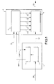
- Figure 1 is schematic representation of a coding system using a pre-processing device according to the invention.
- the coding system comprises a pre-processing device 1 according to the invention and an MPEG 2 coder labelled 2.
- the pre-processing device 1 comprises an image memory 3 and an image analysis device 4.
- the coder 2 comprises a block 6 of processing circuits and a microprocessor 5.
- the pre-processing device 1 is a block of circuits exterior to the MPEG 2 coder.
- the invention relates also to the case where the device 1 is built into the MPEG 2 coder.
- the device 1 and the block 6 then constitute one and the same block of circuits.
- the input signal S1 of the pre-processing device 1 consists of digital images formatted according to the CCIR 601 standard.
- the signal S1 is applied to the input of the image memory 3 which feeds the image analysis device 4.
- the image analysis device 4 makes it possible to perform measurements of spatial and temporal complexities of the various images constituting the signal S1 as well as measurements of detection of change of scene and redundant frame.
- the measurements performed by the device 4 make it possible to construct the cues INF1 applied to the microprocessor 5.
- the delay required in calculating the cues INF1 is applied by the image memory 3 to the images which it stores. Once the analysis has been performed, the images contained in the memory 3 are transmitted to the block 6 of processing circuits of the coder 2.
- the spatial complexity of an image is evaluated by measuring the amount of information which it contains.
- the temporal complexity of an image is effected by measuring the amount of information contained in the image formed by the pixel-to-pixel difference between this image and a temporally earlier reference image.
- the temporally earlier reference image is a motion-compensated image which reproduces the current image and is termed the predicted image.
- the spatial and temporal complexity measurements according to the invention advantageously make it possible accurately to determine the level of difficulty of coding the sequence of images processed.
- the detections of change of scene and of redundant frame can be carried out by observing the differences in luminance between pixels with the same co-ordinates contained in two successive frames of like parity. In the event of a strong similarity between two successive frames of like parity, the second may be declared redundant. Conversely, a large increase in the dissimilarity between two successive frames of like parity is indicative of a change of scene.
- the various measurements mentioned above make it possible to construct the cues INF1 emanating from the analysis device 4 and transmitted to the microprocessor 5.
- these cues there appear, in a non-limiting manner, the type (I, P or B) according to which an image must be coded, the presence of redundant frame in an image, the spatial complexity in the case of an image requiring to be coded as an image of type I, the temporal complexity in the case of an image requiring to be coded as an image of type P or B and the aggregate complexity over a GOP.
- the phrase aggregate complexity over a GOP should be understood to mean a measurement making it possible to derive a complexity cue relating to all the images of one and the same GOP.
- the contents of the cues INF1 are conditioned by a configuration command CONF1 emanating from the microprocessor 5 and applied to the analysis device 4.
- the command CONF1 represents the configuration state of certain parameters of the MPEG 2 coder.
- the microprocessor 5 employs the pre-processing and regulating algorithms which allow the control of the various processing circuits contained in the block 6.
- the processing circuits contained in the block 6 consist, among other things, of a device for horizontal and vertical filtering, a device for rearranging the images, a motion estimator, a coding decision block, a circuit for quantizing the coefficients emanating from the discrete cosine transform, a variable-length coder and the buffer memory of the previously mentioned servocontrol device.
- the cues INF1 used as parameters of the regulating algorithm contribute to generating various commands CM, CF, CT, CQ and CH emanating from the microprocessor 5 and applied to the circuit block 6.
- the command CM is a command applied to the block for coding by quantizing the DCT coefficients. This command makes it possible to define the values of the two sets of 64 coefficients which constitute the intra and inter quantization matrices according to the MPEG 2 video standard.
- the command CM preferably emanates from the cue relating to the aggregate complexity over the GOP to be coded in correlation with the bit rate set-point D.
- the command CF is a command applied to the horizontal and vertical filtering device. This command makes it possible to define the resolution of an image. It is then possible to choose, for example, an image resolution containing 720, 544, 480 or 352 pixels per line.
- the command CF is driven jointly with the command CM with, preferably, the same cues.
- the command CT is a command applied to the device for rearranging the images. This command makes it possible to define the structure of a GOP through the image types (I, P or B) contained in the cues INF1. It is also applied to the coding decision block which must know the image type (I, P or B) which the coding block 6 has to code.
- the command CQ is a command applied to the circuit for quantizing the coefficients emanating from the discrete cosine transform. This command makes it possible to modify the step of the quantization carried out by the quantization circuit so as to comply with the set-point bit rate D applied to the microprocessor 5.
- the complexity measurements as well as the redundant frame cue which are contained in INF1 contribute to constructing the cue contained in the command CQ.
- the command CH is a command applied to the buffer memory of the servocontrol device. It makes it possible to define a header with each GOP and with each image within the GOP.
- the analysis device 4 works on 18 images before any coding operation begins. These 18 images then represent the maximum size allowable for adjusting the GOP of rank k.
- the size of a GOP directly conditions the time lag required by a decoder in order to commence the decoding of the MPEG 2 stream which it receives.
- the maximum size of a GOP is limited by the lag which a user allows in order for the decoder to display the first image.
- a nominal size of GOP of 12 images is commonly used, for example, for the satellite distribution of video programmes in the PAL/625 lines/50 Hz format. In this case, an image lasts 40 ms and the decoder lock-on lag is as much as 12 times 40 ms, i.e. 480 ms.
- the pre-processing device in the case where a strong temporal discontinuity occurs in any one of images 1 to 6 of the forecast GOP of rank k + 1, then the pre-processing device lengthens the GOP of rank k so as to position the first image of the GOP of rank k + 1 on the first image which temporally follows this discontinuity. Conversely, in the case where a strong temporal discontinuity occurs on any one of images 7 to 12 of the GOP of rank k, then the pre-processing device shortens the GOP of rank k so as to position the first image of the GOP of rank k + 1 on the first image which temporally follows this discontinuity.
- the GOP of rank k is then constructed without modifying its boundaries, that is to say, in the example mentioned above, on the basis of a structure with 12 images.
- the bit rate of the coded data which represent the images must comply with the set-point D.
- the regulating algorithm must then adjust to the value D the volume of data coded from one GOP to the next by acting on the command CQ.
- the cues INF1 make it possible to optimize the distribution of the coded data within one and the same GOP. This results in greater effectiveness in the choice of quantization values used for coding the collection of images constituting a GOP and, consequently, an enhancement to the quality of the images perceived.
- Figure 2 is a detailed schematic representation of a first embodiment of the pre-processing device according to the invention.
- the device of Figure 2 comprises two image memories 7 and 8 of FIFO type (the abbreviation FIFO standing for "First In First Out"), a redundant frame and scene change detection module 9, a module 10 for analyzing temporal complexity, a device 11 for analyzing spatial complexity and a GOP structure allocation module 12.
- FIFO FIFO type
- a redundant frame and scene change detection module 9 a module 10 for analyzing temporal complexity
- a device 11 for analyzing spatial complexity for a GOP structure allocation module 12.
- the image memories 7 and 8 are arranged in series and constitute the image memory labelled 3 in Figure 1.
- the signal S1 enters on the image memory 7 and, in parallel, on the redundant frame and scene change detection module 9.
- the CTR signal emanating from the module 9 is transmitted to the module 12.
- the capacity of the image memory 7 corresponds to the difference between Nmax and Nnom, where Nmax represents the maximum size, as defined above, allowable for a GOP and Nnom the nominal size of a GOP, that is to say the size defined, a priori, as that required to be assigned to a GOP.
- the image memory 8 delays the images exiting from the image memory 7 by a depth equal to the maximum allowable size Nmax in such a way that the sending of the cues INF1 relating to a collection of images which is to constitute a GOP starts, at the very latest, at the instant at which the first image of the collection of images exits from the memory 8.
- the images emanating from the image memory 7 are received by the spatial complexity analysis device 11 on its input.
- the device 11 comprises means for implementing the following successive operations: chopping of an image into matrix blocks of 8x8 pixels, DCT transformation on each block, quantization of the coefficients emanating from the DCT, variable-length coding of the quantized coefficients.
- the device 11 Under the action of the command CTRL1 emanating from the module 12, the device 11 generates, image by image, a cue CS1 representing the cost in terms of the number of bits of the image analysed.
- the temporal complexity analysis module 10 comprises an image memory 13, a motion compensation device 14, a differencer 15 and a temporal complexity analysis device 16.
- a difference of images, emanating from the differencer 15 is received by the device 16 on its input.
- This difference of images consists, pixel-to-pixel, of the discrepancy between the current image (applied to the positive input (+) of the differencer 15) and a reference image (applied to the negative input (-) of the differencer 15) emanating from the motion compensation device 14.
- the reference image emanating from the motion compensation device 14 is a predicted image constructed from the current image and from an image stored in the image memory 13.
- the image stored in the image memory 13 is the last image calculated by the module 12 as having to be coded as an image of type P or of type I. It is loaded into the memory 13 under the action of a command CTRL3 emanating from the module 12.
- the motion compensation device 14 can, by choice, deliver a field of vectors at pixel level or else search for the motion vectors over blocks of 8 pixels ⁇ 8 pixels.
- the device 16 comprises means for implementing the following successive operations: chopping of the image difference into matrix blocks of 8 ⁇ 8 pixels, DCT transformation on each block, quantization of the coefficients emanating from the DCT, variable-length coding of the quantized coefficients. Under the action of the command CTRL2 emanating from the module 12 the device 16 generates for each analysed difference of images, a cue CT1 representing the cost in terms of the number of bits of the analysed image difference.
- three cues are available at the image frequency: one cue PDF indicates the presence of a redundant frame in the current image, one cue TYPI gives the type (I, P or B) according to which the current image is to be coded and one cue CXI measures the complexity of the current image (spatial complexity for an image of type I or temporal complexity for an image of type P or B).
- the spatial and temporal complexity measurements are calculated by the module 12.
- the spatial complexity measurement is equal to the product of the cost CS1 times the step of the quantization operation implemented in the device 11.
- the temporal complexity measurement is equal to the product of the cost CT1 times the step of the quantization operation implemented in the device 16.
- the three cues PDF, TYPI and CXI are placed in phase, by any known means, with the signal S2 emanating from the memory 8.
- the GOP structure allocation module 12 also generates a fourth cue CXG, the function of which is to measure the aggregate value of the complexities of the various images constituting a GOP.
- the cue CXG is in phase with the cue CXI which corresponds to the first image of a GOP.
- the collection of cues PDF, TYPI, CXI and CXG constitute the command signal INF1.
- the reference image is a predicted image emanating from the motion estimator 14.
- the invention also relates to the case where the device 10 comprises no motion estimator and where the reference image is directly the image emanating from the memory 13.
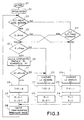
- Figure 3 is a detailed schematic representation in the form of a state diagram of an algorithm implemented in the pre-processing device according to the invention.
- the algorithm of Figure 3 is the algorithm used by the GOP structure allocation facility 12.
- This diagram is traversed temporally from top to bottom in Figure 3. It is implemented with the arrival of each new image at the input of the facility 12 (state E1 at the start and E10 subsequently).
- the initialization phase (state E2) makes it possible to fix the parameters relating to the operation of the module 12, among which may be identified, for example: Nnom, the nominal size of a GOP with no change of scene, Mmax, the maximum number of allowable consecutive images of type B, NS the threshold of comparison between the temporal and spatial complexities. After initialization, these parameters can also be updated with each image (state E10).
- N, M and TYPI mentioned in the diagram of Figure 3 relate to the images processed by the complexity analysis devices 11 and 16 and respectively represent the total number of images already identified in the GOP currently being structured, the number of consecutive images B already identified in the GOP currently being structured and the type of the image just analysed.
- the spatial (Xs) and temporal (Xt) complexity measurements are obtained from the costs CS1 and CT1 emanating respectively from the complexity analysis devices 11 and 16. According to the invention, it is supposed that the temporal complexity cannot be greater than the spatial complexity so that the ratio of the temporal complexity to the spatial complexity takes a value lying between 0 and 1.
- TYPI takes the type I (state E15) and the aggregate complexity CXG is stored before being reset to zero so as to be presented in the cues INF1 in phase with the first image of the GOP which has just terminated.
- the parameters M and N are then re-initialized (state E16) and the memory 13 containing the reference image utilized by the motion estimator 14 is loaded with the current image (state E14).
- the test then amounts to checking whether the ratio between the temporal complexity Xt and the spatial complexity Xs exceeds the threshold NS.
- TYPI takes the value P (state E12) and the memory 13 containing the reference image utilized by the motion estimator 14 is loaded with the current image (state E11).
- the parameter M is reset to zero and the parameter N is incremented by one image (state E13).
- the image complexity cue CXI takes a value proportional to Xs if the image is decreed of type I or a value proportional to Xt if the image is decreed of type P or B.
- the proportionality rules in accordance with the type of the image are defined in the configuration parameters CONF1.
- the aggregate complexity value CXG is then updated by adding the current value CXI.
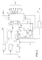
- Figure 4 is a detailed schematic representation of the pre-processing device according to a second embodiment of the invention.
- the device of Figure 4 comprises blocks 7, 8, 9, 10, 11 and 12 such as those described in Figure 2.
- the device according to the second embodiment of the invention comprises a device 17 for measuring noise level and a noise reducer 18.
- the noise reducer 18 has its input linked to the output of the memory 7 and its output linked to the input of the complexity analysis modules 10 and 11 as well as to the input of the image memory 8.
- the device 17 makes it possible to measure, in a manner known per se, the floor video noise level (commonly referred to simply as the "noise floor") of the images constituting the signal S1.
- the noise level measurement NB emanating from the device 17 is transmitted, in the same way as the redundant frame and scene change cues CTR, to the GOP structure allocation module 12.
- the module 12 drives the noise reducer 18 via a command CB.
- This command can, among other things, control the activation or otherwise of the noise filters.
- the noise reducer uses, in a manner known per se, spatio-temporal filtering techniques of the median and recursive types. It can also comprise a motion compensation device such as the device 14 so as to enhance the effectiveness of the filtering performed on the data which represent moving objects.
- the noise level NB emanating from the device 17 is added by the GOP structure allocation module 12 to the cues PDF, TYPI, CXI and CXG so as to form a group of cues INF2.
- the image memory 7 is reduced by the delay introduced by the noise reducer 18 in such a way as to keep the cues INF2 in phase with the images which constitute the signal S2.
- the noise reducer introduces a further lag of three frames.
- Figure 5 represents the schematic of a dynamic bit rate allocation system for MPEG 2 coding using a collection of pre-processing devices according to the invention.
- This system comprises n image sources S11, S12, ..., S1j, ... S1n, n pre-processing devices according to the invention P1, P2, ..., Pj, ... Pn, n MPEG 2 coders C1, C2, ..., Cj, ..., Cn, a bit rate allocation facility OD and a multiplexer MX allowing the various sources to share the same broadcasting channel K.
- the bit rate allocation facility OD allocates each of the coders a bit rate proportional to the complexity of the images to be coded, while guaranteeing, at each instant, that the sum of the bit rates does not exceed the bit rate permitted by the channel.
- the bit rate cue sent by the decision facility to a coder is then applied with a certain delay due to the duration of the exchanges necessary between the decision facility and the coder.
- the bit rate requirement may prove to be very considerable, whereas the coder receives the set-point corresponding to this requirement with several delay images.
- the predictive coding results in a degradation of the images which follow the image representing the change of shot.
- the dynamic bit rate allocation system according to the invention does not have these drawbacks.
- the cues enabling the bit rate allocation facility OD to generate the various bit rate set-points Dj are then either the cues INF1, in the case of a pre-processing device such as that described in Figure 2, or the cue INF2 in the case of a pre-processing device such as that described in Figure 4.
- the bit rate allocation facility OD is then able to generate bit rate set-points Dj without the delay mentioned above.
- the bit rates generated by the facility OD are in accord with the choices of GOP structures of the pre-processing device. This results in a better distribution of the bit rates over the whole of the transmission channel.
- a particularly advantageous application of a bit rate allocation system according to the invention relates to the coding of several sources in the context of direct satellite broadcasting.
Description
- The invention relates to a device for pre-processing video images intended to be coded according to the MPEG 2 video standard.
- A system for coding according to the MPEG 2 video standard uses the properties of the signal in order to reduce its bit rate.
- The coding algorithm employed describes the images in blocks, exploiting the spatial redundancy and the temporal redundancy of the images to be coded.
- The spatial redundancy is evaluated, chiefly, through the succession of three operations: an operation commonly termed discrete cosine transform and denoted DCT, an operation quantizing the coefficients from the DCT and a variable-length coding operation for describing the quantized coefficients from the DCT.
- The temporal redundancy is analysed by a motion compensation operation which consists in searching, using a translation operation for each block of the current image, for the most similar block situated in a reference image. Analysis of the temporal redundancy involves determining a field of translation vectors, commonly termed motion vectors, as well as a prediction error, namely the difference between the signal of the current image and the signal of the image predicted by motion compensation. The prediction error is then analysed according to the principle of spatial redundancy.
-
MPEG 2 coding is a coding of predictive type. It follows that the decoding procedure associated with it must be regularly re-initialized so as to protect the signal from any transmission error or any break in signal due to the toggling of the decoder from one programme to another. - For this purpose, the
MPEG 2 standard provides that, periodically, the images must be coded in spatial mode, that is to say according to a mode which exploits spatial redundancy only. The images coded in spatial mode are commonly termed INTRA images or I images. - The images coded by exploiting temporal redundancy are of two types: there are, on the one hand, those images constructed by reference to a temporally earlier image and, on the other hand, those images constructed by reference to a temporally earlier image and to a temporally later image.
- The coded images constructed by reference to a temporally earlier image are commonly referred to as predicted images or P images and the coded images constructed by reference to a temporally earlier image and to a temporally later image are commonly referred to as bi-directional images or B images.
- An I image is decoded without making reference to images other than itself. A P image is decoded by making reference to the P or I image which precedes it. A B image is decoded by invoking the I or P image which precedes it and the I or P image which follows it.
- The periodicity of the I images defines a group of images commonly denoted GOP (the acronym GOP standing for "Group of Pictures").
- As is known to those skilled in the art, within a given GOP, the amount of data contained in an I image is generally greater than the amount of data contained in a P image and the amount of data contained in a P image is generally greater than the amount of data contained in a B image.
- In order to manage this disparity between the amounts of data depending on the type of image, an
MPEG 2 coder comprises a device for servocontrolling the data bit rate. - Such a servocontrol device makes it possible to control the flow of the coded data. It comprises a buffer memory, for storing the coded data, and models the state of the buffer memory dual to a so-called reference decoder. The servocontrol device smoothes the bit rate of the data exiting the buffer memory in such a way that the sum of the data contained in the coder and in the reference decoder is constant.
- Thus, depending on the type of image (I, P or B) this involves managing the fact that the I images produce a bit rate greater than the mean bit rate (typically equal to 3 to 6 times the mean bit rate), that the P images produce a bit rate near the mean bit rate and that the B images produce a bit rate less than the mean bit rate (typically equal to 0.1 to 0.5 times the mean bit rate).
- According to the prior art, the coding of an I image is performed in two passes. To determine the quantization step required for coding an I image, a proportionality rule is applied as follows:
- Qsp being the value of the quantization step applied for coding the I image during the second pass, Nbsp being the number of bits provided for coding the I image during the second pass, Qpp being the value of the quantization step applied for coding the I image during the first pass, and Nbpp being the number of bits produced by coding the I image during the first pass.
- As regards the coding of the P or B images, the flow control operates according to the assumption of signal stationarity. According to this assumption, each P or B image produces, for the same value of quantization step, a number of bits identical to the number of bits produced by the previous image of the same kind (P or B respectively).
- In the case where the frame frequency of the signal is 60 Hz the video signal to be coded exhibits redundant frames. The
MPEG 2 standard then provides for the possibility of not coding these frames and of transmitting a replication order therefor to the coder. To detect the redundant frames, measurements are performed of the difference in luminance between pixels of successive frames. Such pixel-to-pixel difference measurements do not offer relevant information as regards the kind and the degree of motion contained in the images. It follows that the distribution of the types of images (P or B) in a GOP is generally fixed by the frequency of appearance of images of type P alone. At the very most, the pixel-to-pixel difference measurements allow the detection of a change of scene possibly manifested, in certain cases, through the adjusting of the size of the GOP. - The abovedescribed type of coding of I, P or B images has drawbacks.
- The I image of a GOP is the one with the highest cost in terms of amount of information. The buffer memory mentioned earlier must absorb the very considerable bit rate of this image. According to the prior art, in order to avoid the occurrence of a critical situation upon an increase in the entropy of the signal in the very first few images following the coding of an I image, the cost of the I image is limited so as to preclude the buffer memory of the coder from saturating and the buffer memory of the reference decoder drying up. It is thus usual to prevent the buffer memory of the coder from filling to more than 60 to 70%. This results in a limitation on the quality of the I images.
- Since the I image of a GOP serves as reference in the coding of all the other images of the GOP, the limitation on the quality of an I image entails a limitation on the quality of all the other images of the GOP.
- More generally, when the signal to be coded exhibits substantial modifications, for example upon a change of picture shot, or more generally, upon a sudden variation in the entropy of the signal (the entropy of the signal denotes the amount of intrinsic information which the signal contains), a temporal instability appears in the reproduction of the images. This temporal instability is manifested as a drop in the quality of the images.
- Moreover, as is known to those skilled in the art, an image which corresponds to a considerable variation in the entropy of the signal induces a high cost of coding corresponding to that of an I or P image. Irrespective of the abovementioned drop in the quality of the images, the coding system is then compelled to reduce the bit rate of the images following the image corresponding to the considerable increase in entropy.
- Furthermore, when the coded video signals are intended to be multiplexed with other signals of the same type, the overall bit rate of the multiplex must be shared between the various signals. This configuration arises, for example, when broadcasting video programmes by satellite. In this case, the bit rate of the multiplex may reach 40 Mb/s thus permitting the transport of several programmes simultaneously (10 programmes at 4 Mb/s each for example).
- A video programme emanating from a
MPEG 2 type coding at fixed bit rate exhibits, after decoding, a variation in the quality of the image restored. This stems from the variability of the entropy of the video signal over time, this variability being manifested as a fluctuation in the quantization level of the DCT coefficients. - A suitable allocation of the bit rates associated with the video programmes then allows an overall enhancement in the quality of all the video programmes and/or an increase in the number of programmes broadcast. According to the prior art, the result of coding the GOP of order k is then used as prediction for the expected difficulty in coding the GOP of order k + 1. However, this solution has two drawbacks:
- 1. Should the contents of the video signal vary widely, the result of coding the GOP of index k may differ appreciably from the result of coding the GOP of index k + 1.
- 2. The GOP of index k + 1 may, for optimization reasons, be made to undergo considerable structural variations (the size of the GOP and the distribution of 2. The GOP of index k + 1 may, for optimization reasons, be made to undergo considerable structural variations (the size of the GOP and the distribution of the B and P images within the GOP) with respect to the GOP of index k.
-
- The document EP-A-705041 from Sony corporation on September 22nd, 1995 discloses a method where the scene change detection influences the coding type of the current frame.
- The document EP-A-0708564 from AT&T corporation filed on October, 11th 1995 discloses a method based on statistics using previous frames for the coding of the current frame.
- The document WO9529559 from Thomson Consumer Electronics, filed on April 20th, 1994 discloses a method based on statistical multiplexing.
However, these documents propose methods where the coding type of the current frame is dependent on other frames or on other streams. - Advantageously, the invention makes it possible to overcome these drawbacks by providing, for each GOP to be coded, a prediction of the cost of coding in accord with the structure adopted for this GOP. This prediction is then exploited directly by the bit rate allocator.
- The invention relates to a device for pre-processing images intended to be structured in the form of successive groups of coded images, the first image of each group consisting of an image coded in spatial mode, comprising
- an image memory making it possible to store all the images intended to constitute a group of images and
- an analysis circuit making it possible to read the image memory and comprising
- means to calculate a command comprising,
- for each image read,
- a redundant frame cue,
- a cue giving the type according to which the image is to be coded,
- a cue measuring the complexity of the image and,
- for each image read,
- for all the images constituting a group of
images,
- a cue measuring the aggregate value of the complexities of the various images of the group,
- According to the invention, the means for calculating said command comprise:
- means for calculating
- the cost of coding in spatial mode of each current image read,
- the cost of coding in temporal mode of each current image read,
- the spatial and temporal complexity of an image on the basis of the measurements of the cost of coding in spatial mode and the cost of coding in temporal mode,
- means for calculating the ratio between the measurement of temporal complexity and the measurement of spatial complexity and means for comparing said ratio with a threshold level NS, the value taken by the ratio leading to the choice of an image of type P when it is greater than NS and the choice of an image of type B when it is less than or equal to NS.
- The invention also relates to a device for coding images according to the
MPEG 2 video standard comprising processing circuits for coding the images. The image coding system comprises a device for pre-processing the images according to the invention such as the device mentioned above. - The invention also relates to a video data dynamic bit rate allocation system comprising n devices for coding according to the
MPEG 2 standard, a bit rate allocation facility and a multiplexer allowing the video data emanating from the various coding devices to share the same broadcasting channel. The dynamic bit rate allocation system comprises at least one coding device according to the invention such as that mentioned above, the cues used to generate processing circuit commands emanating from the pre-processing device according to the invention being applied to the bit rate allocation facility. - The pre-processing device according to the invention advantageously makes it possible to define the boundaries of a GOP in an adaptive manner, to distribute in the best possible manner the type (I, P or B) of the various images contained in a GOP and to obtain a prediction of the costs of coding (spatial and temporal) for each image of the GOP.
- As mentioned previously, the images emanating from a source working at 60 Hz contain redundant frames. Advantageously, the invention makes it possible to ascertain the number of redundant frames contained in a GOP and, consequently, to avoid the coding of these frames. This results, overall, in a better strategy for allocating the bit rate of the data representing the images to be coded.
- Other characteristics and advantages of the invention will emerge on reading a preferred embodiment given with reference to the appended figures in which:
- Figure 1 is a schematic representation of a coding system using a pre-processing device according to the invention;
- Figure 2 is a detailed representation of the pre-processing device according to a first embodiment of the invention;
- Figure 3 is a representation, in the form of a state diagram, of an elementary algorithm employed in the pre-processing device according to the invention;
- Figure 4 is a detailed schematic representation of the pre-processing device according to a second embodiment of the invention;
- Figure 5 is a schematic representation of a
dynamic bit rate allocation system for
MPEG 2 coding using a collection of pre-processing devices according to the invention. -
- Figure 1 is schematic representation of a coding system using a pre-processing device according to the invention.
- The coding system comprises a
pre-processing device 1 according to the invention and anMPEG 2 coder labelled 2. Thepre-processing device 1 comprises animage memory 3 and an image analysis device 4. Thecoder 2 comprises a block 6 of processing circuits and amicroprocessor 5. - In Figure 1 the
pre-processing device 1 is a block of circuits exterior to theMPEG 2 coder. However, the invention relates also to the case where thedevice 1 is built into theMPEG 2 coder. Thedevice 1 and the block 6 then constitute one and the same block of circuits. - The input signal S1 of the
pre-processing device 1 consists of digital images formatted according to the CCIR 601 standard. The signal S1 is applied to the input of theimage memory 3 which feeds the image analysis device 4. The image analysis device 4 makes it possible to perform measurements of spatial and temporal complexities of the various images constituting the signal S1 as well as measurements of detection of change of scene and redundant frame. - According to the invention, the measurements performed by the device 4 make it possible to construct the cues INF1 applied to the
microprocessor 5. The delay required in calculating the cues INF1 is applied by theimage memory 3 to the images which it stores. Once the analysis has been performed, the images contained in thememory 3 are transmitted to the block 6 of processing circuits of thecoder 2. - The spatial complexity of an image is evaluated by measuring the amount of information which it contains. The temporal complexity of an image is effected by measuring the amount of information contained in the image formed by the pixel-to-pixel difference between this image and a temporally earlier reference image. Preferably, the temporally earlier reference image is a motion-compensated image which reproduces the current image and is termed the predicted image.
- The spatial and temporal complexity measurements according to the invention advantageously make it possible accurately to determine the level of difficulty of coding the sequence of images processed.
- The detections of change of scene and of redundant frame can be carried out by observing the differences in luminance between pixels with the same co-ordinates contained in two successive frames of like parity. In the event of a strong similarity between two successive frames of like parity, the second may be declared redundant. Conversely, a large increase in the dissimilarity between two successive frames of like parity is indicative of a change of scene.
- The various measurements mentioned above make it possible to construct the cues INF1 emanating from the analysis device 4 and transmitted to the
microprocessor 5. Among these cues there appear, in a non-limiting manner, the type (I, P or B) according to which an image must be coded, the presence of redundant frame in an image, the spatial complexity in the case of an image requiring to be coded as an image of type I, the temporal complexity in the case of an image requiring to be coded as an image of type P or B and the aggregate complexity over a GOP. The phrase aggregate complexity over a GOP should be understood to mean a measurement making it possible to derive a complexity cue relating to all the images of one and the same GOP. By way of non-limiting example, the aggregate complexity of a GOP can be equal to the weighted sum XG such that: - XI, XP, XB represent the complexities relating to the images of respective types I, P and B contained in the GOP;
- KI, KP, KB represent static coefficients associated with the images of respective types I, P and B;
- ΣBGOP is the sum over all the images of type B contained in the GOP;
- ΣPGOP is the sum over all the images of type P contained in the GOP.
-
- The contents of the cues INF1 are conditioned by a configuration command CONF1 emanating from the
microprocessor 5 and applied to the analysis device 4. The command CONF1 represents the configuration state of certain parameters of theMPEG 2 coder. - The
microprocessor 5 employs the pre-processing and regulating algorithms which allow the control of the various processing circuits contained in the block 6. - As is known to those skilled in the art, the processing circuits contained in the block 6 consist, among other things, of a device for horizontal and vertical filtering, a device for rearranging the images, a motion estimator, a coding decision block, a circuit for quantizing the coefficients emanating from the discrete cosine transform, a variable-length coder and the buffer memory of the previously mentioned servocontrol device.
- According to the preferred embodiment of the invention, the cues INF1 used as parameters of the regulating algorithm contribute to generating various commands CM, CF, CT, CQ and CH emanating from the
microprocessor 5 and applied to the circuit block 6. - The command CM is a command applied to the block for coding by quantizing the DCT coefficients. This command makes it possible to define the values of the two sets of 64 coefficients which constitute the intra and inter quantization matrices according to the
MPEG 2 video standard. The command CM preferably emanates from the cue relating to the aggregate complexity over the GOP to be coded in correlation with the bit rate set-point D. - The command CF is a command applied to the horizontal and vertical filtering device. This command makes it possible to define the resolution of an image. It is then possible to choose, for example, an image resolution containing 720, 544, 480 or 352 pixels per line. The command CF is driven jointly with the command CM with, preferably, the same cues.
- The command CT is a command applied to the device for rearranging the images. This command makes it possible to define the structure of a GOP through the image types (I, P or B) contained in the cues INF1. It is also applied to the coding decision block which must know the image type (I, P or B) which the coding block 6 has to code.
- The command CQ is a command applied to the circuit for quantizing the coefficients emanating from the discrete cosine transform. This command makes it possible to modify the step of the quantization carried out by the quantization circuit so as to comply with the set-point bit rate D applied to the
microprocessor 5. The complexity measurements as well as the redundant frame cue which are contained in INF1 contribute to constructing the cue contained in the command CQ. - The command CH is a command applied to the buffer memory of the servocontrol device. It makes it possible to define a header with each GOP and with each image within the GOP.
- The various commands CM, CF, CT and CQ make it possible advantageously to adapt the coding strategy employed by the processing circuits of the block 6.
- By way of example, for a size of GOP defined, a priori, over 12 images, the analysis device 4 works on 18 images before any coding operation begins. These 18 images then represent the maximum size allowable for adjusting the GOP of rank k. As is known to those skilled in the art, the size of a GOP directly conditions the time lag required by a decoder in order to commence the decoding of the
MPEG 2 stream which it receives. Thus, the maximum size of a GOP is limited by the lag which a user allows in order for the decoder to display the first image. A nominal size of GOP of 12 images is commonly used, for example, for the satellite distribution of video programmes in the PAL/625 lines/50 Hz format. In this case, an image lasts 40 ms and the decoder lock-on lag is as much as 12 times 40 ms, i.e. 480 ms. - According to the invention, in the case where a strong temporal discontinuity occurs in any one of
images 1 to 6 of the forecast GOP of rank k + 1, then the pre-processing device lengthens the GOP of rank k so as to position the first image of the GOP of rank k + 1 on the first image which temporally follows this discontinuity. Conversely, in the case where a strong temporal discontinuity occurs on any one ofimages 7 to 12 of the GOP of rank k, then the pre-processing device shortens the GOP of rank k so as to position the first image of the GOP of rank k + 1 on the first image which temporally follows this discontinuity. - In the case where no temporal discontinuity of the images occurs under the conditions mentioned above, the GOP of rank k is then constructed without modifying its boundaries, that is to say, in the example mentioned above, on the basis of a structure with 12 images.
- As is known to those skilled in the art, according to the
MPEG 2 video standard, the bit rate of the coded data which represent the images must comply with the set-point D. The regulating algorithm must then adjust to the value D the volume of data coded from one GOP to the next by acting on the command CQ. - According to the invention, the cues INF1 make it possible to optimize the distribution of the coded data within one and the same GOP. This results in greater effectiveness in the choice of quantization values used for coding the collection of images constituting a GOP and, consequently, an enhancement to the quality of the images perceived.
- Figure 2 is a detailed schematic representation of a first embodiment of the pre-processing device according to the invention.
- The device of Figure 2 comprises two
image memories change detection module 9, amodule 10 for analyzing temporal complexity, adevice 11 for analyzing spatial complexity and a GOPstructure allocation module 12. - The
image memories - The signal S1 enters on the
image memory 7 and, in parallel, on the redundant frame and scenechange detection module 9. The CTR signal emanating from themodule 9 is transmitted to themodule 12. The capacity of theimage memory 7 corresponds to the difference between Nmax and Nnom, where Nmax represents the maximum size, as defined above, allowable for a GOP and Nnom the nominal size of a GOP, that is to say the size defined, a priori, as that required to be assigned to a GOP. - Preferably, the
image memory 8 delays the images exiting from theimage memory 7 by a depth equal to the maximum allowable size Nmax in such a way that the sending of the cues INF1 relating to a collection of images which is to constitute a GOP starts, at the very latest, at the instant at which the first image of the collection of images exits from thememory 8. - The images emanating from the
image memory 7 are received by the spatialcomplexity analysis device 11 on its input. Thedevice 11 comprises means for implementing the following successive operations: chopping of an image into matrix blocks of 8x8 pixels, DCT transformation on each block, quantization of the coefficients emanating from the DCT, variable-length coding of the quantized coefficients. Under the action of the command CTRL1 emanating from themodule 12, thedevice 11 generates, image by image, a cue CS1 representing the cost in terms of the number of bits of the image analysed. - The temporal
complexity analysis module 10 comprises animage memory 13, amotion compensation device 14, adifferencer 15 and a temporalcomplexity analysis device 16. According to the invention, a difference of images, emanating from thedifferencer 15 is received by thedevice 16 on its input. This difference of images consists, pixel-to-pixel, of the discrepancy between the current image (applied to the positive input (+) of the differencer 15) and a reference image (applied to the negative input (-) of the differencer 15) emanating from themotion compensation device 14. - The reference image emanating from the
motion compensation device 14 is a predicted image constructed from the current image and from an image stored in theimage memory 13. The image stored in theimage memory 13 is the last image calculated by themodule 12 as having to be coded as an image of type P or of type I. It is loaded into thememory 13 under the action of a command CTRL3 emanating from themodule 12. Themotion compensation device 14 can, by choice, deliver a field of vectors at pixel level or else search for the motion vectors over blocks of 8 pixels × 8 pixels. - The
device 16 comprises means for implementing the following successive operations: chopping of the image difference into matrix blocks of 8×8 pixels, DCT transformation on each block, quantization of the coefficients emanating from the DCT, variable-length coding of the quantized coefficients. Under the action of the command CTRL2 emanating from themodule 12 thedevice 16 generates for each analysed difference of images, a cue CT1 representing the cost in terms of the number of bits of the analysed image difference. - At the output of the GOP
structure allocation module 12, three cues (PDF, TYPI, CXI) are available at the image frequency: one cue PDF indicates the presence of a redundant frame in the current image, one cue TYPI gives the type (I, P or B) according to which the current image is to be coded and one cue CXI measures the complexity of the current image (spatial complexity for an image of type I or temporal complexity for an image of type P or B). - The spatial and temporal complexity measurements are calculated by the
module 12. The spatial complexity measurement is equal to the product of the cost CS1 times the step of the quantization operation implemented in thedevice 11. The temporal complexity measurement is equal to the product of the cost CT1 times the step of the quantization operation implemented in thedevice 16. - According to the preferred embodiment of the invention, the three cues PDF, TYPI and CXI are placed in phase, by any known means, with the signal S2 emanating from the
memory 8. The GOPstructure allocation module 12 also generates a fourth cue CXG, the function of which is to measure the aggregate value of the complexities of the various images constituting a GOP. According to the preferred embodiment of the invention, the cue CXG is in phase with the cue CXI which corresponds to the first image of a GOP. - The collection of cues PDF, TYPI, CXI and CXG constitute the command signal INF1.
- According to the embodiment of the invention represented in Figure 2, the reference image is a predicted image emanating from the
motion estimator 14. However, the invention also relates to the case where thedevice 10 comprises no motion estimator and where the reference image is directly the image emanating from thememory 13. - Figure 3 is a detailed schematic representation in the form of a state diagram of an algorithm implemented in the pre-processing device according to the invention.
- The algorithm of Figure 3 is the algorithm used by the GOP
structure allocation facility 12. - This diagram is traversed temporally from top to bottom in Figure 3. It is implemented with the arrival of each new image at the input of the facility 12 (state E1 at the start and E10 subsequently). The initialization phase (state E2) makes it possible to fix the parameters relating to the operation of the
module 12, among which may be identified, for example: Nnom, the nominal size of a GOP with no change of scene, Mmax, the maximum number of allowable consecutive images of type B, NS the threshold of comparison between the temporal and spatial complexities. After initialization, these parameters can also be updated with each image (state E10). - The parameters N, M and TYPI mentioned in the diagram of Figure 3 relate to the images processed by the
complexity analysis devices - The spatial (Xs) and temporal (Xt) complexity measurements are obtained from the costs CS1 and CT1 emanating respectively from the
complexity analysis devices - Three possibilities offer themselves for calculating the value of TYPI. The first arises when the parameter N exceeds the value Nnom and when no change of scene or cut has been detected in the images contained in the memory 7 (states E3 and E4 hold true) or when a change of scene is detected in the current image exiting from the memory 7 (states E3 + E17 hold true). In this first case, TYPI takes the type I (state E15) and the aggregate complexity CXG is stored before being reset to zero so as to be presented in the cues INF1 in phase with the first image of the GOP which has just terminated. The parameters M and N are then re-initialized (state E16) and the
memory 13 containing the reference image utilized by themotion estimator 14 is loaded with the current image (state E14). - If the conditions relating to the state E3 and the state E4 are not satisfied, two new tests are carried out. The first consists in checking whether the number of consecutive images of type B exceeds the maximum allowable value (state E5), the second consists in comparing values of the spatial (Xs) and temporal (Xt) complexities calculated previously (state E6) on the basis of the costs CS1 and CT1 emanating from the
complexity analysis devices memory 13 containing the reference image utilized by themotion estimator 14 is loaded with the current image (state E11). In accord with this choice, the parameter M is reset to zero and the parameter N is incremented by one image (state E13). - If the tests relating to the states E5 and E7 do not hold true, the third particular case occurs in which TYPI takes the value B (state E8). In this latter case, the parameters M and N are incremented by one image (state E9).
- For each image processed, with the transition state E10, the image complexity cue CXI takes a value proportional to Xs if the image is decreed of type I or a value proportional to Xt if the image is decreed of type P or B. The proportionality rules in accordance with the type of the image are defined in the configuration parameters CONF1. The aggregate complexity value CXG is then updated by adding the current value CXI.
- Figure 4 is a detailed schematic representation of the pre-processing device according to a second embodiment of the invention.
- The device of Figure 4 comprises
blocks blocks device 17 for measuring noise level and anoise reducer 18. Thedevice 17, placed in parallel with themodule 9, receives the signal S1 on its input. Thenoise reducer 18 has its input linked to the output of thememory 7 and its output linked to the input of thecomplexity analysis modules image memory 8. - The
device 17 makes it possible to measure, in a manner known per se, the floor video noise level (commonly referred to simply as the "noise floor") of the images constituting the signal S1. The noise level measurement NB emanating from thedevice 17 is transmitted, in the same way as the redundant frame and scene change cues CTR, to the GOPstructure allocation module 12. In return, themodule 12 drives thenoise reducer 18 via a command CB. This command can, among other things, control the activation or otherwise of the noise filters. - The noise reducer uses, in a manner known per se, spatio-temporal filtering techniques of the median and recursive types. It can also comprise a motion compensation device such as the
device 14 so as to enhance the effectiveness of the filtering performed on the data which represent moving objects. - The noise level NB emanating from the
device 17 is added by the GOPstructure allocation module 12 to the cues PDF, TYPI, CXI and CXG so as to form a group of cues INF2. - The
image memory 7 is reduced by the delay introduced by thenoise reducer 18 in such a way as to keep the cues INF2 in phase with the images which constitute the signal S2. According to the preferred embodiment, the noise reducer introduces a further lag of three frames. - Figure 5 represents the schematic of a dynamic bit rate allocation system for
MPEG 2 coding using a collection of pre-processing devices according to the invention. - This system comprises n image sources S11, S12, ..., S1j, ... S1n, n pre-processing devices according to the invention P1, P2, ..., Pj, ... Pn,
n MPEG 2 coders C1, C2, ..., Cj, ..., Cn, a bit rate allocation facility OD and a multiplexer MX allowing the various sources to share the same broadcasting channel K. As represented in Figure 1, the video signal S2j (j = 1, 2, ..., n) which emanates from the pre-processing device Pj is transmitted to the coder Cj and the command CONFj emanating from the coder Cj is applied to the pre-processing device Pj. - According to the prior art (i.e. when the system does not contain any pre-processing device according to the invention), the bit rate allocation facility OD allocates each of the coders a bit rate proportional to the complexity of the images to be coded, while guaranteeing, at each instant, that the sum of the bit rates does not exceed the bit rate permitted by the channel. As is known to those skilled in the art, the bit rate cue sent by the decision facility to a coder is then applied with a certain delay due to the duration of the exchanges necessary between the decision facility and the coder.
- In particular, upon a change of shot, the bit rate requirement may prove to be very considerable, whereas the coder receives the set-point corresponding to this requirement with several delay images. The predictive coding results in a degradation of the images which follow the image representing the change of shot.
- The dynamic bit rate allocation system according to the invention does not have these drawbacks.
- According to the invention, each
MPEG 2 coder Cj (j = 1, 2, ..., n) is preceded by a pre-processing device Pj such as one of those described in Figure 2 or 4. The cues enabling the bit rate allocation facility OD to generate the various bit rate set-points Dj are then either the cues INF1, in the case of a pre-processing device such as that described in Figure 2, or the cue INF2 in the case of a pre-processing device such as that described in Figure 4. - In Figure 5, the cues INF1 or INF2 are denoted CPXj generically for the pre-processing device of order j.
- Advantageously, under the action of cues CPXj, the bit rate allocation facility OD is then able to generate bit rate set-points Dj without the delay mentioned above. Moreover, the bit rates generated by the facility OD are in accord with the choices of GOP structures of the pre-processing device. This results in a better distribution of the bit rates over the whole of the transmission channel.
- A particularly advantageous application of a bit rate allocation system according to the invention relates to the coding of several sources in the context of direct satellite broadcasting.
Claims (8)
- Device (1) for pre-processing images intended to be structured in the form of successive groups (GOP) of coded images, the first image of each group consisting of an image coded in spatial mode, comprisingcharacterized in that the means (12) for calculating said command comprisean image memory (3) making it possible to store all the images intended to constitute a group of images (GOP) andan analysis circuit (4) making it possible to read the image memory (3) and comprisingmeans (12) to calculate a command (INF1) comprising,for each image read,a redundant frame cue (PDF),a cue (TYPI) giving a type according to which the image is to be coded,a cue (CXI) measuring the complexity of the image and,for all the images constituting a group of images (GOP),a cue measuring the aggregate value of the complexities of the various images of the group,means for calculatingthe cost of coding in spatial mode (CS1) of each current image read,the cost of coding in temporal mode (CT1) of each current image read,the spatial and temporal complexity of an image on the basis of the measurements of the cost of coding in spatial mode (CS1) and the cost of coding in temporal mode (CT1)means for calculating the ratio between the measurement of temporal complexity and the measurement of spatial complexity and means for comparing said ratio with a threshold level NS, the value taken by the ratio leading to the choice of an image of type P when it is greater than NS and the choice of an image of type B when it is less than or equal to NS.
- Device according to claim 1 characterized in that it comprises means for detecting a change of scene and redundant frame and in that the means for calculating said command calculate said command on the basis of the signal from the redundant frame and scene detection means
- Device according to claim 2 characterized in that the means for measuring the cost of coding in temporal mode (CT1) comprise an image memory (13) containing a reference image and a differencer (15) making it possible to take the difference between the current image read and the reference image.
- Device according to claim 2, characterized in that the means (11) for measuring the cost of coding in temporal mode (CT1) comprise an image memory (13) containing a reference image, a motion estimator (14) making it possible to construct a predicted image on the basis of the current image read and of the reference image and a differencer (15) making it possible to take the difference between the current image read and the predicted image emanating from the motion estimator (14).
- Device according to claim 3 or 4 characterized in that it comprises means for applying a command (CTRL3) making it possible to load into the image memory (13), as reference image, an image requiring to be coded as an image of type P or as an image of type I.
- Device (1) according to any one of Claims 2 to 5, characterized in that it comprises a noise level (NB) measurement device (17) mounted in parallel with the means (9) for detecting a change of scene and redundant frame and in that the image memory (3) for storing all the images constituting a group of images comprises a first image memory (7) and a second image memory (8) and in that said device comprises a noise reducer (18) whose input is linked to the output of the first image memory (7) and whose output is linked to the input of the second image memory (8).
- Device for coding images according to the MPEG 2 video standard comprising processing circuits (6) for coding the images, characterized in that it comprises a device (1) for pre-processing the images according to any one of Claims 1 to 6, the pre-processing device (1) making it possible to generate cues (INF1, INF2) used to generate commands (CF, CR, CD, CQ, CM) for the processing circuits (6).
- Video data dynamic bit rate allocation system comprising n devices for coding according to the MPEG 2 video standard, a bit rate allocation facility (OD) and a multiplexer (MX) allowing the video data emanating from the various coding devices to share the same broadcasting channel (K), characterized in that at least one coding device is a coding device according to Claim 7 and in that the cues (INF1, INF2) used to generate processing circuit commands emanating from the pre-processing circuit (1) are applied to the bit rate allocation facility (OD).
Applications Claiming Priority (2)
| Application Number | Priority Date | Filing Date | Title |
|---|---|---|---|
| FR9706461 | 1997-05-27 | ||
| FR9706461A FR2764156B1 (en) | 1997-05-27 | 1997-05-27 | PRETREATMENT DEVICE FOR MPEG II CODING |
Publications (2)
| Publication Number | Publication Date |
|---|---|
| EP0881836A1 EP0881836A1 (en) | 1998-12-02 |
| EP0881836B1 true EP0881836B1 (en) | 2004-11-17 |
Family
ID=9507270
Family Applications (1)
| Application Number | Title | Priority Date | Filing Date |
|---|---|---|---|
| EP98400824A Expired - Lifetime EP0881836B1 (en) | 1997-05-27 | 1998-04-07 | Pre-processing device for MPEG 2 coding |
Country Status (5)
| Country | Link |
|---|---|
| US (1) | US6229925B1 (en) |
| EP (1) | EP0881836B1 (en) |
| JP (1) | JP4404975B2 (en) |
| DE (1) | DE69827548T2 (en) |
| FR (1) | FR2764156B1 (en) |
Cited By (1)
| Publication number | Priority date | Publication date | Assignee | Title |
|---|---|---|---|---|
| US9602840B2 (en) | 2006-02-06 | 2017-03-21 | Thomson Licensing | Method and apparatus for adaptive group of pictures (GOP) structure selection |
Families Citing this family (39)
| Publication number | Priority date | Publication date | Assignee | Title |
|---|---|---|---|---|
| FR2790899B1 (en) * | 1999-03-09 | 2001-04-20 | Thomson Broadcast Systems | DEVICE AND METHOD FOR REGULATING THROUGHPUT IN A SYSTEM FOR STATISTICAL MULTIPLEXING OF STREAMS OF IMAGES CODED ACCORDING TO MPEG 2 CODING |
| IL134182A (en) | 2000-01-23 | 2006-08-01 | Vls Com Ltd | Method and apparatus for visual lossless pre-processing |
| US6879988B2 (en) * | 2000-03-09 | 2005-04-12 | Pkware | System and method for manipulating and managing computer archive files |
| JP2003531533A (en) * | 2000-04-18 | 2003-10-21 | コーニンクレッカ フィリップス エレクトロニクス エヌ ヴィ | Bitrate allocation in joint bitrate transcoding |
| US6753929B1 (en) | 2000-06-28 | 2004-06-22 | Vls Com Ltd. | Method and system for real time motion picture segmentation and superposition |
| US6631163B1 (en) * | 2000-11-14 | 2003-10-07 | Koninklijke Philips Electronics N.V. | Dynamic adaptation of complexity in an MPEG-2 scalable decoder |
| JP4203707B2 (en) * | 2001-01-31 | 2009-01-07 | 日本電気株式会社 | A moving picture coding apparatus, a moving picture coding method, and a program using the prior analysis. |
| US6996183B2 (en) * | 2001-09-26 | 2006-02-07 | Thomson Licensing | Scene cut detection in a video bitstream |
| US20030123538A1 (en) * | 2001-12-21 | 2003-07-03 | Michael Krause | Video recording and encoding in devices with limited processing capabilities |
| KR100850705B1 (en) * | 2002-03-09 | 2008-08-06 | 삼성전자주식회사 | Method for adaptive encoding motion image based on the temperal and spatial complexity and apparatus thereof |
| US7042943B2 (en) | 2002-11-08 | 2006-05-09 | Apple Computer, Inc. | Method and apparatus for control of rate-distortion tradeoff by mode selection in video encoders |
| DE10313457A1 (en) * | 2003-03-25 | 2004-10-14 | Henkel Kgaa | Washing or cleaning agents |
| DE10313458A1 (en) * | 2003-03-25 | 2004-11-18 | Henkel Kgaa | Detergents or cleaning agents |
| DE10313455A1 (en) * | 2003-03-25 | 2004-10-14 | Henkel Kgaa | Detergents and cleaning agents |
| FR2857205B1 (en) * | 2003-07-04 | 2005-09-23 | Nextream France | DEVICE AND METHOD FOR VIDEO DATA CODING |
| JP3914212B2 (en) * | 2004-03-05 | 2007-05-16 | 日本電信電話株式会社 | Moving picture coding apparatus, moving picture coding method, moving picture coding program, and computer-readable recording medium recording the program |
| CA2565670A1 (en) | 2004-05-04 | 2005-11-17 | Qualcomm Incorporated | Method and apparatus for motion compensated frame rate up conversion |
| US8406293B2 (en) * | 2004-06-27 | 2013-03-26 | Apple Inc. | Multi-pass video encoding based on different quantization parameters |
| US8005139B2 (en) * | 2004-06-27 | 2011-08-23 | Apple Inc. | Encoding with visual masking |
| EP1774779A2 (en) | 2004-07-01 | 2007-04-18 | QUALCOMM Incorporated | Method and apparatus for using frame rate up conversion techniques in scalable video coding |
| BRPI0513527A (en) | 2004-07-20 | 2008-05-06 | Qualcomm Inc | Method and Equipment for Video Frame Compression Assisted Frame Rate Upward Conversion (EA-FRUC) |
| US8553776B2 (en) | 2004-07-21 | 2013-10-08 | QUALCOMM Inorporated | Method and apparatus for motion vector assignment |
| US7903902B2 (en) | 2004-07-26 | 2011-03-08 | Sheraizin Semion M | Adaptive image improvement |
| US7639892B2 (en) * | 2004-07-26 | 2009-12-29 | Sheraizin Semion M | Adaptive image improvement |
| US8780957B2 (en) * | 2005-01-14 | 2014-07-15 | Qualcomm Incorporated | Optimal weights for MMSE space-time equalizer of multicode CDMA system |
| US7526142B2 (en) * | 2005-02-22 | 2009-04-28 | Sheraizin Vitaly S | Enhancement of decompressed video |
| RU2402885C2 (en) * | 2005-03-10 | 2010-10-27 | Квэлкомм Инкорпорейтед | Classification of content for processing multimedia data |
| US8208536B2 (en) * | 2005-04-28 | 2012-06-26 | Apple Inc. | Method and apparatus for encoding using single pass rate controller |
| US9113147B2 (en) | 2005-09-27 | 2015-08-18 | Qualcomm Incorporated | Scalability techniques based on content information |
| US20070206117A1 (en) * | 2005-10-17 | 2007-09-06 | Qualcomm Incorporated | Motion and apparatus for spatio-temporal deinterlacing aided by motion compensation for field-based video |
| US8948260B2 (en) | 2005-10-17 | 2015-02-03 | Qualcomm Incorporated | Adaptive GOP structure in video streaming |
| US8204104B2 (en) * | 2006-03-09 | 2012-06-19 | Sony Corporation | Frame rate conversion system, method of converting frame rate, transmitter, and receiver |
| US20070230564A1 (en) * | 2006-03-29 | 2007-10-04 | Qualcomm Incorporated | Video processing with scalability |
| US8634463B2 (en) | 2006-04-04 | 2014-01-21 | Qualcomm Incorporated | Apparatus and method of enhanced frame interpolation in video compression |
| US8750387B2 (en) | 2006-04-04 | 2014-06-10 | Qualcomm Incorporated | Adaptive encoder-assisted frame rate up conversion |
| US9131164B2 (en) | 2006-04-04 | 2015-09-08 | Qualcomm Incorporated | Preprocessor method and apparatus |
| CN102037730B (en) * | 2008-05-22 | 2013-06-12 | 爱立信电话股份有限公司 | Content adaptive video encoder and coding method |
| US8976857B2 (en) * | 2011-09-23 | 2015-03-10 | Microsoft Technology Licensing, Llc | Quality-based video compression |
| KR102049644B1 (en) * | 2017-12-12 | 2019-11-28 | 전자부품연구원 | Hierarchical Noise Reduction Method for Efficient Coding of Video with Noise |
Family Cites Families (18)
| Publication number | Priority date | Publication date | Assignee | Title |
|---|---|---|---|---|
| US5134480A (en) * | 1990-08-31 | 1992-07-28 | The Trustees Of Columbia University In The City Of New York | Time-recursive deinterlace processing for television-type signals |
| JPH06233277A (en) * | 1993-02-05 | 1994-08-19 | Sharp Corp | Picture encoder |
| BE1007490A3 (en) * | 1993-09-10 | 1995-07-11 | Philips Electronics Nv | DEVICE FOR TRANSFERRING a plurality of TELEVISION SIGNALS OVER A TRANSMISSION CHANNEL. |
| US5734755A (en) * | 1994-03-11 | 1998-03-31 | The Trustees Of Columbia University In The City Of New York | JPEG/MPEG decoder-compatible optimized thresholding for image and video signal compression |
| KR100314329B1 (en) * | 1994-04-20 | 2001-12-28 | 크리트먼 어윈 엠 | Multiplexer Using Constant Bit Rate Encoder |
| JP3711571B2 (en) * | 1994-09-29 | 2005-11-02 | ソニー株式会社 | Image coding apparatus and image coding method |
| US5621468A (en) * | 1994-10-07 | 1997-04-15 | Daewoo Electronics Co., Ltd. | Motion adaptive spatio-temporal filtering of video signals |
| US5734419A (en) * | 1994-10-21 | 1998-03-31 | Lucent Technologies Inc. | Method of encoder control |
| FR2728129A1 (en) * | 1994-12-13 | 1996-06-14 | Matra Communication | DEVICE FOR DIGITAL MULTIPLEXING OF VIDEO PROGRAMS |
| JP3694912B2 (en) * | 1995-02-23 | 2005-09-14 | 株式会社日立製作所 | Memory control method and image decoding apparatus |
| JP3353604B2 (en) * | 1995-08-09 | 2002-12-03 | ソニー株式会社 | Moving image encoding method and apparatus, and signal recording medium |
| JPH0974566A (en) * | 1995-09-04 | 1997-03-18 | Sony Corp | Compression encoder and recording device for compression encoded data |
| EP0778707B1 (en) * | 1995-12-06 | 2002-06-19 | THOMSON multimedia | Apparatus for pre-processing of a digital video data stream |
| US5963256A (en) * | 1996-01-11 | 1999-10-05 | Sony Corporation | Coding according to degree of coding difficulty in conformity with a target bit rate |
| US5867221A (en) * | 1996-03-29 | 1999-02-02 | Interated Systems, Inc. | Method and system for the fractal compression of data using an integrated circuit for discrete cosine transform compression/decompression |
| GB9607645D0 (en) * | 1996-04-12 | 1996-06-12 | Snell & Wilcox Ltd | Processing of video signals prior to compression |
| GB9611455D0 (en) * | 1996-05-29 | 1996-08-07 | Digi Media Vision Ltd | Method and apparatus for processing a digital signal |
| JPH10136380A (en) * | 1996-10-31 | 1998-05-22 | Matsushita Electric Ind Co Ltd | Device and method for encoding moving image |
-
1997
- 1997-05-27 FR FR9706461A patent/FR2764156B1/en not_active Expired - Fee Related
-
1998
- 1998-04-07 EP EP98400824A patent/EP0881836B1/en not_active Expired - Lifetime
- 1998-04-07 DE DE69827548T patent/DE69827548T2/en not_active Expired - Lifetime
- 1998-05-19 US US09/081,447 patent/US6229925B1/en not_active Expired - Lifetime
- 1998-05-25 JP JP14327398A patent/JP4404975B2/en not_active Expired - Lifetime
Cited By (1)
| Publication number | Priority date | Publication date | Assignee | Title |
|---|---|---|---|---|
| US9602840B2 (en) | 2006-02-06 | 2017-03-21 | Thomson Licensing | Method and apparatus for adaptive group of pictures (GOP) structure selection |
Also Published As
| Publication number | Publication date |
|---|---|
| EP0881836A1 (en) | 1998-12-02 |
| JP4404975B2 (en) | 2010-01-27 |
| FR2764156A1 (en) | 1998-12-04 |
| DE69827548T2 (en) | 2005-12-08 |
| JPH10336663A (en) | 1998-12-18 |
| DE69827548D1 (en) | 2004-12-23 |
| FR2764156B1 (en) | 1999-11-05 |
| US6229925B1 (en) | 2001-05-08 |
Similar Documents
| Publication | Publication Date | Title |
|---|---|---|
| EP0881836B1 (en) | Pre-processing device for MPEG 2 coding | |
| EP0959627B1 (en) | A motion video compression system with adaptive bit allocation and quantization | |
| US6678322B1 (en) | Video data coding device, video data coding method, video data transmitting device, and video data recording medium | |
| US6614935B2 (en) | Two-pass encoding method of digital motion video sequences for constant-or variable bit rate | |
| US6522693B1 (en) | System and method for reencoding segments of buffer constrained video streams | |
| US5214507A (en) | Video signal quantization for an mpeg like coding environment | |
| US6181742B1 (en) | Single pass target allocation for video encoding | |
| EP0660612B1 (en) | Image encoding apparatus | |
| US6563954B2 (en) | Method for computational graceful degradation in an audiovisual compression system | |
| KR100298416B1 (en) | Method and apparatus for block classification and adaptive bit allocation | |
| US7079581B2 (en) | Apparatus and method for controlling variable bit rate in real time | |
| CA2011034C (en) | A highly efficient coding apparatus | |
| GB2309611A (en) | A motion video compression system with buffer empty/fill look-ahead bit allocation | |
| EP0998151A2 (en) | Joint data rate control for stereoscopic video signal coding | |
| CA2355389A1 (en) | Statistical multiplex system, statistical multiplex controller and method of statistical multiplex | |
| US6714592B1 (en) | Picture information conversion method and apparatus | |
| US5652629A (en) | Bidirectional motion estimation in a motion video compression system | |
| US6654416B1 (en) | Device and process for regulating bit rate in system for the statistical multiplexing of image streams coded according to MPEG2 coding | |
| JPH08275158A (en) | Moving image compression system with guaranteed bit generation limit | |
| US7856054B1 (en) | Scene change identification during encoding of compressed video | |
| US6226326B1 (en) | Coding device and coding method | |
| US6243417B1 (en) | Device and method for encoding image data, and image data transmission method | |
| EP0888009B1 (en) | Device and method for encoding image data, and image data transmission method | |
| JPH0662393A (en) | Multiplexed dynamic image encoding method and device | |
| US7050497B2 (en) | Process and device for the video coding of high definition images |
Legal Events
| Date | Code | Title | Description |
|---|---|---|---|
| PUAI | Public reference made under article 153(3) epc to a published international application that has entered the european phase |
Free format text: ORIGINAL CODE: 0009012 |
|
| AK | Designated contracting states |
Kind code of ref document: A1 Designated state(s): AT BE CH LI Kind code of ref document: A1 Designated state(s): DE FR GB |
|
| AX | Request for extension of the european patent |
Free format text: AL;LT;LV;MK;RO;SI |
|
| 17P | Request for examination filed |
Effective date: 19990416 |
|
| AKX | Designation fees paid |
Free format text: AT BE CH LI |
|
| RBV | Designated contracting states (corrected) |
Designated state(s): DE FR GB |
|
| REG | Reference to a national code |
Ref country code: DE Ref legal event code: 8566 |
|
| 17Q | First examination report despatched |
Effective date: 20010809 |
|
| GRAP | Despatch of communication of intention to grant a patent |
Free format text: ORIGINAL CODE: EPIDOSNIGR1 |
|
| GRAS | Grant fee paid |
Free format text: ORIGINAL CODE: EPIDOSNIGR3 |
|
| GRAA | (expected) grant |
Free format text: ORIGINAL CODE: 0009210 |
|
| AK | Designated contracting states |
Kind code of ref document: B1 Designated state(s): DE FR GB |
|
| REG | Reference to a national code |
Ref country code: GB Ref legal event code: FG4D |
|
| REF | Corresponds to: |
Ref document number: 69827548 Country of ref document: DE Date of ref document: 20041223 Kind code of ref document: P |
|
| PLBE | No opposition filed within time limit |
Free format text: ORIGINAL CODE: 0009261 |
|
| STAA | Information on the status of an ep patent application or granted ep patent |
Free format text: STATUS: NO OPPOSITION FILED WITHIN TIME LIMIT |
|
| ET | Fr: translation filed | ||
| 26N | No opposition filed |
Effective date: 20050818 |
|
| REG | Reference to a national code |
Ref country code: DE Ref legal event code: R082 Ref document number: 69827548 Country of ref document: DE Ref country code: DE Ref legal event code: R082 Ref document number: 69827548 Country of ref document: DE Representative=s name: ROSSMANITH, MANFRED, DIPL.-PHYS. DR.RER.NAT., DE |
|
| REG | Reference to a national code |
Ref country code: DE Ref legal event code: R082 Ref document number: 69827548 Country of ref document: DE |
|
| REG | Reference to a national code |
Ref country code: FR Ref legal event code: TP Owner name: FRANCE BREVETS, FR Effective date: 20150708 Ref country code: FR Ref legal event code: TP Owner name: FRANCE BREVETS, FR Effective date: 20150715 Ref country code: FR Ref legal event code: TP Owner name: FRANCE BREVETS, FR Effective date: 20150709 Ref country code: FR Ref legal event code: CD Owner name: FRANCE BREVETS, FR Effective date: 20150709 Ref country code: FR Ref legal event code: CD Owner name: FRANCE BREVETS, FR Effective date: 20150708 Ref country code: FR Ref legal event code: CA Effective date: 20150709 |
|
| REG | Reference to a national code |
Ref country code: FR Ref legal event code: PLFP Year of fee payment: 19 |
|
| REG | Reference to a national code |
Ref country code: FR Ref legal event code: PLFP Year of fee payment: 20 |
|
| PGFP | Annual fee paid to national office [announced via postgrant information from national office to epo] |
Ref country code: FR Payment date: 20170413 Year of fee payment: 20 Ref country code: DE Payment date: 20170404 Year of fee payment: 20 Ref country code: GB Payment date: 20170404 Year of fee payment: 20 |
|
| REG | Reference to a national code |
Ref country code: DE Ref legal event code: R071 Ref document number: 69827548 Country of ref document: DE |
|
| REG | Reference to a national code |
Ref country code: GB Ref legal event code: PE20 Expiry date: 20180406 |
|
| PG25 | Lapsed in a contracting state [announced via postgrant information from national office to epo] |
Ref country code: GB Free format text: LAPSE BECAUSE OF EXPIRATION OF PROTECTION Effective date: 20180406 |