EP0882595A2 - Ink level estimation using drop count and ink level sense - Google Patents
Ink level estimation using drop count and ink level sense Download PDFInfo
- Publication number
- EP0882595A2 EP0882595A2 EP98103480A EP98103480A EP0882595A2 EP 0882595 A2 EP0882595 A2 EP 0882595A2 EP 98103480 A EP98103480 A EP 98103480A EP 98103480 A EP98103480 A EP 98103480A EP 0882595 A2 EP0882595 A2 EP 0882595A2
- Authority
- EP
- European Patent Office
- Prior art keywords
- ink
- volume
- remaining
- providing
- estimate
- Prior art date
- Legal status (The legal status is an assumption and is not a legal conclusion. Google has not performed a legal analysis and makes no representation as to the accuracy of the status listed.)
- Granted
Links
Images


Classifications
-
- B—PERFORMING OPERATIONS; TRANSPORTING
- B41—PRINTING; LINING MACHINES; TYPEWRITERS; STAMPS
- B41J—TYPEWRITERS; SELECTIVE PRINTING MECHANISMS, i.e. MECHANISMS PRINTING OTHERWISE THAN FROM A FORME; CORRECTION OF TYPOGRAPHICAL ERRORS
- B41J2/00—Typewriters or selective printing mechanisms characterised by the printing or marking process for which they are designed
- B41J2/005—Typewriters or selective printing mechanisms characterised by the printing or marking process for which they are designed characterised by bringing liquid or particles selectively into contact with a printing material
- B41J2/01—Ink jet
- B41J2/17—Ink jet characterised by ink handling
- B41J2/175—Ink supply systems ; Circuit parts therefor
- B41J2/17503—Ink cartridges
- B41J2/17543—Cartridge presence detection or type identification
- B41J2/17546—Cartridge presence detection or type identification electronically
-
- B—PERFORMING OPERATIONS; TRANSPORTING
- B41—PRINTING; LINING MACHINES; TYPEWRITERS; STAMPS
- B41J—TYPEWRITERS; SELECTIVE PRINTING MECHANISMS, i.e. MECHANISMS PRINTING OTHERWISE THAN FROM A FORME; CORRECTION OF TYPOGRAPHICAL ERRORS
- B41J2/00—Typewriters or selective printing mechanisms characterised by the printing or marking process for which they are designed
- B41J2/005—Typewriters or selective printing mechanisms characterised by the printing or marking process for which they are designed characterised by bringing liquid or particles selectively into contact with a printing material
- B41J2/01—Ink jet
- B41J2/17—Ink jet characterised by ink handling
- B41J2/175—Ink supply systems ; Circuit parts therefor
- B41J2/17566—Ink level or ink residue control
-
- B—PERFORMING OPERATIONS; TRANSPORTING
- B41—PRINTING; LINING MACHINES; TYPEWRITERS; STAMPS
- B41J—TYPEWRITERS; SELECTIVE PRINTING MECHANISMS, i.e. MECHANISMS PRINTING OTHERWISE THAN FROM A FORME; CORRECTION OF TYPOGRAPHICAL ERRORS
- B41J2/00—Typewriters or selective printing mechanisms characterised by the printing or marking process for which they are designed
- B41J2/005—Typewriters or selective printing mechanisms characterised by the printing or marking process for which they are designed characterised by bringing liquid or particles selectively into contact with a printing material
- B41J2/01—Ink jet
- B41J2/17—Ink jet characterised by ink handling
- B41J2/175—Ink supply systems ; Circuit parts therefor
- B41J2/17503—Ink cartridges
- B41J2/17513—Inner structure
- B41J2002/17516—Inner structure comprising a collapsible ink holder, e.g. a flexible bag
-
- B—PERFORMING OPERATIONS; TRANSPORTING
- B41—PRINTING; LINING MACHINES; TYPEWRITERS; STAMPS
- B41J—TYPEWRITERS; SELECTIVE PRINTING MECHANISMS, i.e. MECHANISMS PRINTING OTHERWISE THAN FROM A FORME; CORRECTION OF TYPOGRAPHICAL ERRORS
- B41J2/00—Typewriters or selective printing mechanisms characterised by the printing or marking process for which they are designed
- B41J2/005—Typewriters or selective printing mechanisms characterised by the printing or marking process for which they are designed characterised by bringing liquid or particles selectively into contact with a printing material
- B41J2/01—Ink jet
- B41J2/17—Ink jet characterised by ink handling
- B41J2/175—Ink supply systems ; Circuit parts therefor
- B41J2/17566—Ink level or ink residue control
- B41J2002/17569—Ink level or ink residue control based on the amount printed or to be printed
-
- B—PERFORMING OPERATIONS; TRANSPORTING
- B41—PRINTING; LINING MACHINES; TYPEWRITERS; STAMPS
- B41J—TYPEWRITERS; SELECTIVE PRINTING MECHANISMS, i.e. MECHANISMS PRINTING OTHERWISE THAN FROM A FORME; CORRECTION OF TYPOGRAPHICAL ERRORS
- B41J2/00—Typewriters or selective printing mechanisms characterised by the printing or marking process for which they are designed
- B41J2/005—Typewriters or selective printing mechanisms characterised by the printing or marking process for which they are designed characterised by bringing liquid or particles selectively into contact with a printing material
- B41J2/01—Ink jet
- B41J2/17—Ink jet characterised by ink handling
- B41J2/175—Ink supply systems ; Circuit parts therefor
- B41J2/17566—Ink level or ink residue control
- B41J2002/17586—Ink level or ink residue control using ink bag deformation for ink level indication
Definitions
- the disclosed invention relates to ink jet printing systems that employ replaceable consumable parts including ink cartridges, and more particularly to mechanisms for estimating the amount of ink remaining in an ink cartridge.
- ink jet printing is relatively well developed.
- Commercial products such as computer printers, graphics plotters, and facsimile machines have been implemented with ink jet technology for producing printed media.
- an ink jet image is formed pursuant to precise placement on a print medium of ink drops emitted by an ink drop generating device known as an ink jet printhead.
- an ink jet printhead is supported on a movable carriage that traverses over the surface of the print medium and is controlled to eject drops of ink at appropriate times pursuant to command of a microcomputer or other controller, wherein the timing of the application of the ink drops is intended to correspond to a pattern of pixels of the image being printed.
- Some known printers make use of an ink container that is separably replaceable from the printhead. When the ink container is exhausted it is removed and replaced with a new ink container.
- replaceable ink containers that are separate from the printhead allow users to replace the ink container without replacing the printhead. The printhead is then replaced at or near the end of printhead life, and not when the ink container is replaced.
- ink jet printing systems that employ ink containers that are separate from the printheads.
- a known approach to estimating remaining ink volume involves immersing electrodes in an ink volume and measuring a resistance path through the ink. Considerations with this approach include the complexity of incorporating electrodes in an ink container, and the variation of electrical properties with ink formulation.
- One aspect of the invention is directed to an ink container that includes an ink reservoir, a memory device for providing an ink drop count based available volume of ink, and an ink level sensing circuit for providing an ink level sense output that is indicative of a sensed volume of ink.
- Another aspect of the invention is directed to a method that estimates remaining ink volume pursuant to drop counting based on (1) a nominal ink drop volume when the estimated remaining ink volume is greater than a selected level, and (2) a calibrated and then recalibrated ink drop volume when the estimated remaining ink volume is reduced, wherein the recalibrated drop volume is based on a sensed ink volume.
- a further aspect of the invention is directed to estimating remaining ink volume pursuant to ink drop counting over a first estimated ink volume range and ink volume sensing over a second estimated ink volume range.
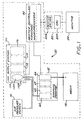
- FIG. 1 set forth therein is a schematic block diagram of a printer/plotter 50 in which the invention can be employed.
- the invention generally contemplates estimating remaining ink volume in an ink container pursuant to ink drop counting and ink level sensing in a manner that optimizes the accuracy of the estimate.
- a scanning print carriage 52 holds a plurality of print cartridges 60-66 which are fluidically coupled to an ink supply station 100 that supplies pressurized ink to the print cartridges 60-66.
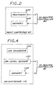
- each of the cartridges 60-66 comprises an ink jet printhead and an integral printhead memory, as schematically depicted in FIG. 2 for the representative example of the print cartridge 60 which includes an ink jet printhead 60A and an integral printhead memory 60B.
- Each print cartridge has a fluidic regulator valve that opens and closes to maintain a slight negative gauge pressure in the cartridge that is optimal for printhead performance.
- the ink provided to each of the cartridges 60-66 is pressurized to reduce the effects of dynamic pressure drops.
- the ink supply station 100 contains receptacles or bays for accepting ink containers 110-116 which are respectively associated with and fluidically connected to respective print cartridges 60-66.
- Each of the ink containers 110-116 includes a collapsible ink reservoir, such as collapsible ink reservoir 110A that is surrounded by an air pressure chamber 110B.
- An air pressure source or pump 70 is in communication with the air pressure chamber for pressurizing the collapsible ink reservoir.
- one pressure pump supplies pressurized air for all ink containers in the system.
- Pressurized ink is delivered to the print cartridges by an ink flow path that includes for example respective flexible plastic tubes connected between the ink containers 110-116 and respectively associated print cartridges 60-66.
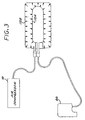
- FIG. 3 is a simplified diagrammatic view illustrating the pressure source 70, the print cartridge 66, and the collapsible ink reservoir 110a and pressure chamber 110B.
- the pressure chamber 110B (which is defined by a pressure vessel, as more particularly described herein) is allowed to de-pressurize. Also, the ink containers 110-116 are not pressurized during shipment.
- each of the ink containers 110-116 comprises an ink reservoir, an ink level sensing circuit, and an integral ink cartridge memory, as schematically depicted in FIG. 4 for the representative example of the ink container 110 which more particularly includes the ink reservoir 110A, an ink level sensing circuit 110C, and an integral ink cartridge memory 110D.
- the scanning print carriage 52, the print cartridges 60-66, and the ink containers 110-114 are electrically interconnected to a printer microprocessor controller 80 that includes printer electronics and firmware for the control of various printer functions, including analog-to-digital converter circuitry for converting the outputs of the ink level sensing circuits of the ink containers 110-116.
- the controller 80 thus controls the scan carriage drive system and the printheads on the print carriage to selectively energize the printheads, to cause ink droplets to be ejected in a controlled fashion on the print medium 40.
- the printer controller 80 further continually estimates remaining ink volume in each of the ink containers 110-114, as described more fully herein.
- a host processor 82 which includes a CPU 82A and a software printer driver 82B, is connected to the printer controller 82.
- the host processor 82 comprises a personal computer that is external to the printer 50.
- a monitor 84 is connected to the host processor 82 and is used to display various messages that are indicative of the state of the ink jet printer.
- the printer can be configured for stand-alone or networked operation wherein messages are displayed on a front panel of the printer.
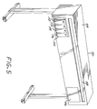
- FIG. 5 shows in isometric view an exemplary form of a large format printer/plotter in which the invention can be employed, wherein four off-carriage ink containers 110, 112, 114, 116 are show in place in an ink supply station.
- the printer/plotter of FIG. 5 further includes a housing 54, a front control panel 56 which provides user control switches, and a media output slot 58. While this exemplary printer/plotter is fed from a media roll, it should be appreciated that alternative sheet feed mechanisms can also be used.
- the print cartridge memories including print cartridge memory 60B, the ink container memories including ink container memory 110C, and the ink level sensing circuits including ink level sensing circuit 110D enable the controller 82 to determine estimates of the amounts of ink contained in the ink containers 110-116.
- each of the printhead memories and the ink container memories includes both factory written data and printer-recorded data.
- each of the ink container memories stores factory written ink supply volume data (i.e., factory fill volume) and printer recorded ink drop coarse count and fine count data, while each of the print cartridge memories stores factory written nominal ink drop volume data.
- the fine count data comprises an 8-bit word, with each bit corresponding to 1/256 of 12.5% of the total supply volume of the corresponding ink container.
- the coarse count data comprises an 8-bit write-once word wherein bits are progressively written each time the fine count data overflows or "rolls over", such that a coarse count bit is written each time ink drop usage tracking indicates 12.5% of the ink in the ink cartridge is consumed.
- the number of written bits in the coarse count data indicates the number of times the fine count data has overflowed.
- the print cartridge nominal drop volume parameter and the ink container supply volume are read to calculate the number N of ink drops required to cause one fine count bit to toggle (i.e., an amount equal to 1/256 of 12.5% of the total supply volume), and ink usage is tracked by counting ink drops (for example by counting ink firing signals supplied to a printhead) and incrementing the fine count data each time the ink drop count reaches N, wherein the ink drop count is re-started after reaching N.
- the fine count data is incremented after every firing of N drops, wherein N is the number of ink drops required to cause one fine count bit to toggle.
- the coarse count data and the fine count data for a particular cartridge are indicative of the percentage amount of ink used.
- An estimate of remaining ink volume is calculated from the coarse count data, fine count data, nominal drop volume, and ink supply size data.
- FIG. 6 set forth therein is a flow diagram of a procedure for estimating remaining ink volume in accordance with the invention that would be separately implemented for each of the ink containers 110-114 and which optimally uses ink drop count information and ink level sense information to provide more accurate ink level estimation.
- the estimated remaining ink volume can be used to control an ink "gas gauge" that is displayed for the user for example via the monitor 84 (FIG. 1) or the printer front panel 56 (FIG. 5).
- a remaining ink volume estimate for an ink container is periodically determined pursuant to the coarse count data, the fine count data, and a nominal drop volume until (A) the ink level sensing circuit for the ink container becomes active before the ink volume estimate falls below a first predetermined reference volume, or (B) the ink volume estimate falls below the first predetermined reference volume and the ink level sensing circuit has not become active, where such first predetermined reference volume is selected such that the ink level sensing circuit, if properly operating, will become active before the ink drop based ink volume estimate reaches such first predetermined reference volume.
- the first predetermined reference volume can be 23% of available ink volume, wherein available ink volume refers to the ink that is available for consumption while stranding a small amount of ink for even the worst case tolerances of determining remaining ink volume.
- a remaining ink volume estimate is periodically determined pursuant to coarse count, fine count, and nominal ink drop volume until a sensed volume estimate based on the ink level sense information falls below a second reference volume (e.g., 40% of available ink) that is selected to insure that the ink level sensing circuit provides an accurate indication of the volume of the remaining ink.
- a second reference volume e.g. 40% of available ink
- ink drop volume is calibrated to arrive at a first calibrated ink drop volume, and at 217 a remaining ink volume is periodically determined pursuant to coarse count, fine count, and the first calibrated ink drop volume until a sensed volume estimate based on ink level sense information falls below a third reference volume (e.g., 33% of available ink) that is selected to insure that the ink level sensing circuit provides an accurate indication of the remaining ink volume.
- a third reference volume e.g., 33% of available ink
- the ink drop volume is again calibrated to arrive at a second calibrated ink drop volume, and at 221 a remaining ink volume estimate is periodically determined pursuant to coarse count, fine count, and the second calibrated ink drop volume until the ink drop based remaining ink volume estimate falls below a fourth predetermined reference volume (e.g., 14% of available ink).
- a fourth predetermined reference volume e.g. 14% of available ink.
- a low ink level warning is provided to the user, and at 225 a remaining ink volume estimate is periodically determined pursuant to coarse count, fine count, and the second calibrated ink drop volume until the ink drop based remaining ink volume estimate falls below a fifth predetermined reference volume.
- a very low ink level warning is provided to the user, and at 229 a remaining ink volume estimate is periodically determined pursuant to coarse count, fine count, and the second calibrated ink drop volume until the ink drop based remaining ink volume estimate falls below 0% available ink.
- printing stops stranding a small amount of ink.
- remaining ink level is estimated pursuant to drop count information and a first calibrated ink drop volume (in 213) and then a second calibrated ink drop volume (in 217), wherein the calibrated ink drop volumes are determined from remaining ink levels that are sensed or inferred from the ink level sense information provided the ink level sensing circuit.
- Drop volume is calibrated two times so as to utilize the most accurate ink level sense information.
- a single calibrated drop volume can be utilized for remaining ink estimation over the estimation range covered by the steps at 213 and 217.
- the first and second calibrated values can be compared with each other and if the difference between the two is greater than a predetermined value, a decision can be made to ignore one of the calibrated values, which may require adjustment of the estimation if the first calibrated value needs to be ignored.
- a remaining ink volume estimate is periodically determined pursuant to coarse count, fine count, and nominal drop volume until the remaining ink volume estimate falls below a sixth reference volume which is less than the first reference volume (e.g., 6% of available ink).
- a user warning of low ink level is issued, and at 245 a remaining ink volume estimate is periodically determined pursuant to coarse count, fine count, and nominal drop volume until the remaining ink volume estimate falls below 0% of available ink.
- printing stops As described earlier, the calculation of remaining ink volume estimates is made in such a manner that insures some small amount of ink will be stranded when the estimate reaches 0% remaining ink volume, so as to avoid potentially damaging dry printing.
- the foregoing procedure estimates remaining ink volume pursuant to drop counting based on (1) a nominal ink drop volume when the estimated remaining ink volume is greater than a selected level, and (2) a calibrated and then recalibrated ink drop volume when the remaining ink volume is low.
- Calibration and recalibration are based on the output of the ink level sensing circuit which is configured so as to be very accurate over a predetermined actual ink remaining volume that is selected to be close to the depleted state. In this manner, ink drop volume is accurately calibrated as the remaining volume approaches the depleted state, and the accuracy of the estimate of remaining ink volume is advantageously increased as actual remaining ink volume approaches the desired amount to be stranded.
- a calibrated ink drop volume is arrived at by determining an average ink drop volume from a reading of the ink level sensing circuit output, and the corresponding coarse count data and the fine count data.
- ink drop volume is calibrated pursuant to the difference between the ink drop data (coarse count and fine count) for two readings of the ink level sensing circuit output.
- the nominal ink drop volume can also be utilized in arriving at a calibrated drop volume, for example by averaging the calculated drop volume and the nominal drop volume.
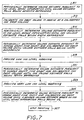
- FIG. 7 set forth therein is a flow diagram of an alternative sub-procedure in accordance with the invention for estimating remaining ink volume in an ink container after a determination at 215 that the ink level sensing circuit of the ink container has become active before the ink volume estimate falls below the first predetermined ink drop reference level.
- a remaining ink volume estimate is periodically determined pursuant to the ink level sense information provided by the ink level sensing circuit until the remaining ink volume estimate falls below a seventh reference volume.
- ink drop volume is calibrated, and at 315 a remaining ink volume estimate is periodically determined pursuant to the ink level sense information provided by the ink level sensing circuit until the remaining ink volume estimate falls below an eighth predetermined reference volume.
- a remaining ink volume estimate is periodically determined pursuant to coarse count, fine count, and the calibrated ink drop volume until the ink drop based remaining ink level decreases to less than or equal to a ninth predetermined reference volume.
- remaining ink volume is estimated at 317 by reference to absolute ink volume as sensed by the ink level sensing circuit at the time ink volume estimation by ink drop count resumes, for example wherein ink drop based remaining ink volume estimation is referenced to a reference coarse count and fine count that correspond to the remaining ink volume as sensed by the ink level sensing circuit at the time remaining ink level estimation by ink drop count resumes.
- a low ink level warning is provided to the user, and at 321 remaining ink volume is determined pursuant to coarse count, fine count, and the calibrated ink drop volume until the remaining ink volume estimate falls below a tenth predetermined reference volume.
- a very low ink level warning is provided to the user, and at 325 a remaining ink volume estimate is periodically determined pursuant to coarse count, fine Count, and the second calibrated ink drop volume until the ink drop calculated ink drop volume falls to or below 0% available ink.
- printing stops stranding a small amount of ink.
- remaining ink volume of an ink cartridge is estimated pursuant the output of the ink level sensing circuit of the ink cartridge while the estimated remaining ink volume, as sensed by the level sensing circuit, is in the range over which the ink level sensing circuit is reasonably accurate. Then, as the actual remaining ink volume approaches the depleted state, remaining ink volume is estimated on the basis of coarse count, fine count and an ink level sensing circuit calibrated ink drop volume.
- the ink level sensing circuit is utilized while it is accurate, and the resumed ink drop based remaining ink volume estimation is more accurate as a result of ink drop volume calibration as well as being referenced to an ink level that is sensed by the ink level sensing circuit.
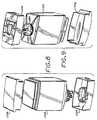
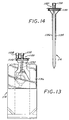
- FIGS. 8-15 schematically illustrated therein is a specific implementation of an ink container 200 which includes an ink level sensing circuit in accordance with the invention, and which can be implemented as each of the ink containers 110-116 which are structurally substantially identical.
- the ink container 200 generally includes a pressure vessel 1102, a chassis member 1120 attached to a neck region 1102A at a leading end of the pressure vessel 1102, a leading end cap 1104 attached to the leading end of the pressure vessel, and a trailing end cap 1106 attached to the trailing end of the pressure vessel 1102.
- the ink container 200 further includes a collapsible ink bag or reservoir 114 disposed within the pressure vessel 1102, and an ink level sensing (ILS) circuit 1170 attached to the collapsible ink reservoir 114.
- the collapsible ink reservoir 114 is sealingly attached to a keel portion 1292 of the chassis 1120 which seals the interior of the pressure vessel 1102 from outside atmosphere while providing for an air inlet 1108 to the interior of the pressure vessel 1102, an ink outlet port 1110 for ink contained in the ink reservoir 114 and routing for conductive traces between the ink level sensing circuit 1170 and externally accessible contact pads disposed on the chassis member.
- the chassis 1120 is secured to the opening of the neck region 1102A of the pressure vessel 1102, for example by an annular crimp ring 1280 that engages a top flange of the pressure vessel and an abutting flange of the chassis member.
- a pressure sealing O-ring 1152 suitably captured in a circumferential groove on the chassis 1120 engages the inside surface of the neck region 1102A of the pressure vessel 1102.
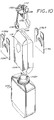
- the collapsible ink reservoir 114 more particularly comprises a pleated bag having opposing walls or sides 1114, 1116, and the ink level sensing circuit 1170 more particularly includes first and second substantially flat spiral inductive coils 1130, 1132 disposed on the opposing sides 1114, 1116.
- an elongated sheet of bag material is folded such that opposed lateral edges of the sheet overlap or are brought together, forming an elongated cylinder.
- the lateral edges are sealed together, and pleats are in the resulting structure generally in alignment with the seal of the lateral edges.
- the bottom or non-feed end of the bag is formed by heat sealing the pleated structure along a seam transverse to the seal of the lateral edges.
- the top or feed end of the ink reservoir is formed similarly while leaving an opening for the bag to be sealingly attached to the keel portion 1292 of the chassis 1120.
- the ink reservoir bag is sealingly attached to keel portion 1292 by heat staking.
- the ink reservoir 114 has a longitudinal axis that extends from feed end to non-feed end, and is parallel to the axis of the ink outlet port 1110.
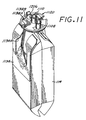
- Stiffening elements 1134, 1136 are disposed on the opposing sides 1114, 1116 over the flat spiral inductive coils 1130, 1132 to enable a more predictable, consistent, and repeatable collapse of the ink reservoir 114 as the ink contained therein is depleted, to maintain the coils parallel to each other as the ink reservoir walls collapse toward each other while the remaining ink volume is in the range over which the ink level sensing circuit is active, and to reduce buckling of the ink reservoir in the region between the coils and the portion of the ink reservoir that is attached to the keel portion 1292.
- Maintaining the coils parallel to each other over a collapse range of interest with a more predictable, repeatable, and consistent collapse allows for more accurate sensing of ink remaining in the reservoir by adjacent the stiffening elements 1134, 1136.
- Pressurization within the pressure vessel also provides for more predictable and consistent collapse of the ink reservoir, with or without the stiffening elements 1134, 1136.
- each of the stiffener 1134, 1136 extends laterally across the wall to which it is attached, and includes a cut-out 1134A, 1136A that provides clearance for folds, bumps or wrinkles in the walls 1114, 1116 caused by the keel portion 1292 and by the attachment of the ink reservoir to the keel portion 1292.
- Each stiffener further extends longitudinally from the feed end of the ink reservoir to a location slightly beyond the side of the coil that is away from the feed end of the ink reservoir.
- the stiffening elements reduce buckling of the walls 1114, 1116 between the coils and the feed end of the ink reservoir and allow buckling at the non-feed end of the ink reservoir.
- the stiffening elements 1134, 1136 are preferably flat resiliently deformable stiff sheets that return to a planar configuration in the absence of the biasing forces applied to bend the stiffening elements for insertion into the pressure vessel.
- the stiffening elements are stiff and yet sufficiently resilient so as to be not permanently deformed by the curling required for insertion into the pressure vessel.
- the stiffening elements comprise relatively thin (e.g., .0005 inches) polyethylene terephthalate (PET) sheets.
- the stiffening elements effectively cooperate with the walls of the ink reservoir to form wall regions of increased stiffness whose collapse with ink depletion is consistent and repeatable, and it should be appreciated that regions of the opposite walls 1114, 1116 of the ink reservoir can be formed as regions of increased stiffness in which case the stiffening elements 1134, 1136 can be omitted.
- Each of the spiral coils 1130, 1132 can comprise a continuously curved winding having a perimeter that is generally defined by a conical section such as a circle or ellipse, for example, or each spiral coil can comprise a segmented winding comprised of serially connected segments having a perimeter that is generally defined by a polygon as a rectangle.
- the spiral coils 1130, 1132 are preferably positioned such that the line formed by their geometrical centers is orthogonal to the planes of the coils when the planes of the coils are parallel and when the ink reservoir is flat and without ink. In other words, the spiral coils 1130, 1132 are positioned such that their geometrical centers are substantially mirror images of each other on the walls 1114, 1116.
- the container 200 is preferably rotationally positioned about its longitudinal axis, which extends between the open end thereof and the opposite closed end, such that the planes of the coils are vertical.
- the areas of the stiffening elements 1134, 1136 are preferably greater than the areas of the respectively adjacent coils 1130, 1132. Also, the areas of the coils 1130, 1132 are respectively contained within the areas of the respectively adjacent stiffening elements 1134, 1136 (or rigid regions).
- the ink level sensing circuit 1170 can be used without pressurization.
- the ink level sensing circuit 1170 is implemented, for example, as a flexible circuit wherein the flat coils 1130, 1132 and associated conductive elements by which the flat coils can be electrically accessed are disposed in laminar fashion between first and second flat unitary flexible substrates.
- the ink level sensing circuit further includes conductive leads 1142A, 1142B which extend between the flat coil 1130 and externally accessible contact pads 1138A, 1138B; and conductive leads 1144A, 1144B which extend between the flat coil 1132 and externally accessible contact pads 1140A, 1140B.
- the foregoing contact pads are exposed by respective openings in the appropriate flexible substrate of the flexible circuit, and are externally accessible in the sense that they can be conductively engaged by contact elements external to the ink container 200.
- the externally accessible contact pads of the ink level sensing circuit are suitably disposed on the outside of the chassis 1120, and the conductive leads extend generally longitudinally within the pressure vessel 1102 from the chassis 1120 to the coils 1130, 1132. Portions of the conductive leads and associated portions of the flexible substrates of the ink level sensing circuit 1170 pass on the outside surface of the chassis between the O-ring 1152 and such outside surface.
- a suitably insulated jumper 1174 is connected between the conductive lead 1142A and the center of the flat coil 1130, while a suitable insulated jumper 1176 is connected between the conductive lead 1144A and the center of the flat coil 1132.
- the ink level sensing circuit further includes ink leakage detectors comprised of conductive ink leakage detection pads 1180, 1182 respectively located adjacent the coils 1130, 1132 and respectively connected to conductive leads 1142B, 1144B.
- the ink leakage pads 1180, 1182 are exposed by openings in the outward facing flexible substrate of the ink sensing flexible circuit and are not covered by the stiffening elements 1134, 1136 so as to be contactable with any ink that accumulates in the pressure vessel 1102 as a result of ink leakage.
- Ink leakage indicative of a broken ink reservoir, is detected for example by applying a voltage between the contact pad 1138B and a reference potential, and sensing the voltage between the contact pad 1140B and the reference potential.
- the contact pad 1140B would be at a non-zero voltage; otherwise, the contact pad 1140B would be at zero volts.
- the ink leakage contact pads 1180, 1182 are preferably rotationally positioned relative to the coils 1130, 1132 so as to be elevationally low when the ink container is in its intended installed position.
- the coil portions and the contact portions of the flexible circuit comprising the ink level sensing circuit 1170 are attached to the walls 1114, 1116 and the chassis 1120 with pressure sensitive adhesive.
- a memory chip package 1206 is also supported on the chassis 1120, for example between pairs of externally accessible ink level sensing circuit contact pads 1138A, 1138B and 1140A, 1140B.
- the memory chip package includes memory access contacts which are connected to the print controller 82 when the ink container 200 is installed in the printing system 50, as are the externally accessible ink level sensing circuit contact pads 1138A, 1138B, 1140A, 1140B.
- the coils 1130, 1132 function as a non-contactive inductive transducer that indirectly senses the amount of ink in the ink reservoir by sensing the separation between the opposing walls 1114, 1116 which collapse toward each other as the ink supply is depleted.
- An AC excitation signal is passed through one coil (considered the input coil), inducing a voltage in the other coil (considered the output coil) whose magnitude increases as the separation decreases.
- the change in voltage in the output coil results from the change in the mutual inductance of the coils with change in the separation between the coils.
- the output voltage provided by the output coil is readily related to a corresponding ink volume, e.g., by values stored in the ink container memory.
- the coils 1130, 1132 are positioned in areas of the ink reservoir that are subject to predictable, consistent and repeatable collapse. Further, the coils 1130, 1132 are positioned such that the ink level sensing circuit 1170 is active over a desired range of ink volume.
- the spiral coils 1130, 1132 are positioned closer to the ink outlet 1110, for example between the feed end of the reservoir which is attached to the chassis 1120 and the middle between the feed end of the ink reservoir and the opposite end.
- the ink container 200 can be installed with the longitudinal axis of the container being tilted relative to horizontal by an angle in the range of about 5 to 30 degrees such that the chassis is elevationally lower that the opposite of the ink container, and with the ink container rotationally positioned about the longitudinal axis so that the planes of the ink level sensing coils are vertical.
- the coils can be positioned slightly off the lateral middle (wherein the lateral direction is orthogonal to the longitudinal direction) for installations wherein longitudinal axis of the ink reservoir is more horizontal than vertical.
- the ink level sensing coils can be displaced toward what would be the elevationally higher edge of the walls 1114, 1116 by about 4 degrees, for example, whereby the coils are tilted up in the installed position relative to the longitudinal axis of the ink reservoir.
- the coil area of the coil 1132 is larger than the coil area of the coil 1130, as the input coil, in at least one direction and not smaller than the coil area of the coil 1130 in any direction, such that if the output coil area and the input coil area were superimposed, the output coil area would completely overlap the input coil area and extend beyond the input coil area in at least one direction, wherein the coil area of a coil is the area occupied by the turns of the coil and the gap between adjacent turns.
- a coil area can be also considered as the area enclosed by the periphery of a coil.
- the input coil area can be completely contained within the output coil area, if such areas were placed on top of each other.
- the output coil area and input coil can be similarly shaped (i.e., of the same shape), and the output coil area would have a bigger shape.
- the coil area of the output coil has a radius that is greater than the radius of the coil area of the input coil.
- the output coil area would have a width that is greater than the width of the input coil, and a length that is greater than or equal to the length of the input coil.
- the input coil area is completely containable within the output coil area which greater than the input coil area in at least one dimension or direction.
- the coil 1132 as the output coil, includes a greater number of turns than the coil 1130, as the input coil, without limitation as to the relative areas of the coils.
- a larger output coil area that completely contains the input coil area and extends beyond the output coil area in at least one direction increases the tolerance in the alignment between the coils 1130, 1132 in at least one direction, which allows for easier manufacture.
- a larger number of turns in the output coil increases the level of the voltage of the coil output, which increases the accuracy of ink volume sensing.
Abstract
Description
Claims (15)
- All ink container for an ink jet printing system having an ink jet printhead that selectively deposits ink drops on print media, the ink container comprising:an ink reservoir (110A) for storing ink to be provided to the ink jet printhead;an information storage device (110D) for storing information indicative of an available volume of ink in said ink reservoir;an ink level sensing circuit (110C) for providing an ink level sense information that is indicative of a sensed volume of ink in said ink reservoir; and
wherein said storage device information and said ink level sense information are utilized to provide an estimation of remaining ink level. - The ink container of Claim 1 wherein:said ink reservoir comprises a collapsible reservoir; andsaid ink level sensing circuit is disposed on said collapsible reservoir.
- The ink container of Claim 2 wherein said ink level sensing circuit comprises an ink level sensing transducer for sensing a degree of collapse of said collapsible reservoir.
- The ink container of Claim 3 wherein said ink level sensing transducer comprises an inductive coil (1130, 1132).
- The ink container of Claim 1 wherein said storage device stored information is indicative of an initial ink capacity of said ink reservoir.
- The ink container of Claim 1 wherein said storage device information is indicative of an estimated volume of ink remaining in said ink reservoir.
- The ink container of Claim 6 wherein said storage device information indicative of an estimated volume of remaining ink is periodically updated.
- The ink container of Claim 1 wherein said ink level sensing circuit is active over a sensing range of actual ink level contained in said ink reservoir, wherein said sensing range is intermediate a maximum actual ink level and a minimum actual ink level.
- The ink container of Claim 1 wherein said ink reservoir is replaceable separately from the printhead.
- A method for determining an amount of ink remaining in an ink container installed in a printing system having an ink jet printhead for receiving ink from the ink container and selectively depositing ink drops on print media, the method comprising the steps of:providing a calculated remaining ink volume based on ink drop count information and a printhead drop volume estimate;providing a sensed remaining ink volume based on the sensed ink volume information; andproviding an ink volume estimate based on the calculated remaining ink volume and the sensed remaining ink volume.
- The method of Claim 10 wherein the step of providing an ink volume estimate includes the steps of:providing an ink volume estimate that corresponds to the calculated remaining ink volume while the sensed remaining ink volume is greater than a predetermined threshold; andproviding an ink volume estimate that corresponds to the sensed remaining ink volume while the sensed remaining ink volume is less than the predetermined threshold.
- The method of Claim 11 wherein the step of providing an ink volume estimate further includes the steps of:determining a revised printhead drop volume estimate based on drop count information and a sensed remaining ink volume that is less than the predetermined threshold and greater than another predetermined threshold;providing an updated calculated remaining ink volume based on the ink drop count information and the revised printhead drop volume estimate; andproviding an ink volume estimate that corresponds to the updated calculated remaining ink volume while the sensed remaining ink volume is less than the another predetermined threshold.
- The method of Claim 10 wherein the step of providing an ink volume estimate includes the steps of:providing an ink volume estimate that corresponds to the calculated remaining ink volume while the sensed remaining ink volume is greater than a predetermined threshold;determining a revised printhead drop volume estimate based on drop count information and a sensed remaining ink volume when the sensed remaining ink volume reaches the predetermined threshold;providing an updated calculated remaining ink volume based on the ink drop count information and the revised printhead drop volume estimate; andproviding an ink volume estimate that corresponds to the updated calculated remaining ink volume.
- The method of Claim 10 wherein the step of providing an ink volume estimate includes the steps of:providing an ink volume estimate that corresponds to the sensed remaining ink volume while the sensed remaining ink volume is greater than a predetermined threshold; andproviding an ink volume estimate that corresponds to the calculated remaining ink volume while the sensed remaining ink volume is less than the predetermined threshold.
- The method of Claim 14 wherein the printhead drop volume estimate is based on a sensed remaining ink volume and ink drop count information.
Applications Claiming Priority (2)
| Application Number | Priority Date | Filing Date | Title |
|---|---|---|---|
| US869122 | 1997-06-04 | ||
| US08/869,122 US6151039A (en) | 1997-06-04 | 1997-06-04 | Ink level estimation using drop count and ink level sense |
Publications (3)
| Publication Number | Publication Date |
|---|---|
| EP0882595A2 true EP0882595A2 (en) | 1998-12-09 |
| EP0882595A3 EP0882595A3 (en) | 2000-03-29 |
| EP0882595B1 EP0882595B1 (en) | 2003-11-19 |
Family
ID=25352957
Family Applications (1)
| Application Number | Title | Priority Date | Filing Date |
|---|---|---|---|
| EP98103480A Expired - Lifetime EP0882595B1 (en) | 1997-06-04 | 1998-02-27 | Ink level estimation using drop count and ink level sense |
Country Status (7)
| Country | Link |
|---|---|
| US (1) | US6151039A (en) |
| EP (1) | EP0882595B1 (en) |
| JP (1) | JP4286339B2 (en) |
| KR (1) | KR100546494B1 (en) |
| CN (1) | CN1151362C (en) |
| DE (1) | DE69819815T2 (en) |
| ES (1) | ES2206773T3 (en) |
Cited By (13)
| Publication number | Priority date | Publication date | Assignee | Title |
|---|---|---|---|---|
| DE19958948A1 (en) * | 1999-11-26 | 2001-06-07 | Francotyp Postalia Gmbh | Method for determining the number of prints that can be carried out with a residual amount of ink and arrangement for carrying out the method |
| EP1145857A2 (en) * | 2000-04-11 | 2001-10-17 | Seiko Epson Corporation | Liquid jetting apparatus |
| EP1170135A1 (en) * | 2000-01-18 | 2002-01-09 | Seiko Epson Corporation | Ink cartridge, ink jet type recording device using the ink cartridge, and cleaning control method for recording head of the recording device |
| EP1190859A2 (en) * | 2000-09-19 | 2002-03-27 | Seiko Epson Corporation | Optional mountable element and ink cartridge |
| EP1199177A1 (en) * | 2000-10-17 | 2002-04-24 | Seiko Epson Corporation | Ink bag and recording apparatus incorporating the same |
| US7014286B2 (en) | 2000-04-11 | 2006-03-21 | Seiko Epson Corporation | Liquid jetting apparatus |
| EP1747891A2 (en) * | 2005-07-26 | 2007-01-31 | Océ-Technologies B.V. | Method of controlling of an ink jet printer and ink jet printer |
| WO2008079482A2 (en) * | 2006-10-27 | 2008-07-03 | Static Control Components, Inc. | Method and apparatus for spoofing imaging devices |
| CN100540316C (en) * | 2006-05-31 | 2009-09-16 | 精工爱普生株式会社 | Liquid consuming device and liquid-consumed buret reason devices and methods therefor |
| EP2171569A2 (en) * | 2007-06-21 | 2010-04-07 | Hewlett-Packard Development Company, L.P. | Systems and methods for managing facsimile documents |
| FR2954216A1 (en) * | 2009-12-23 | 2011-06-24 | Markem Imaje | SYSTEM FOR MEASURING IN A FLUID CIRCUIT OF A CONTINUOUS INK JET PRINTER, ASSOCIATED FLUID CIRCUIT AND BLOCK FOR IMPLEMENTING SUCH A MEASURING SYSTEM |
| FR2954215A1 (en) * | 2009-12-23 | 2011-06-24 | Markem Imaje | SYSTEM FOR DETERMINING AUTONOMY IN CONSUMABLE FLUIDS OF A CONTINUOUS INK-JET PRINTER |
| US8366233B2 (en) | 2005-12-26 | 2013-02-05 | Seiko Epson Corporation | Printing material container, and board mounted on printing material container |
Families Citing this family (86)
| Publication number | Priority date | Publication date | Assignee | Title |
|---|---|---|---|---|
| KR100225075B1 (en) * | 1997-11-04 | 1999-10-15 | 윤종용 | Motor driver circuit |
| JPH11138771A (en) * | 1997-11-06 | 1999-05-25 | Brother Ind Ltd | Ink-jet printer |
| JPH11314375A (en) * | 1998-05-08 | 1999-11-16 | Funai Electric Co Ltd | Residual quantity detector of ink in ink cartridge |
| JPH11348319A (en) * | 1998-06-03 | 1999-12-21 | Canon Inc | Ink jet recording apparatus and control thereof |
| JP2000218818A (en) * | 1998-11-26 | 2000-08-08 | Seiko Epson Corp | Ink container and printer using the same |
| US6799820B1 (en) * | 1999-05-20 | 2004-10-05 | Seiko Epson Corporation | Liquid container having a liquid detecting device |
| JP4632140B2 (en) * | 2000-04-11 | 2011-02-16 | セイコーエプソン株式会社 | Liquid ejector |
| JP2002234182A (en) | 2001-02-09 | 2002-08-20 | Canon Inc | Ink-jet recording apparatus, ink information detecting apparatus, ink information detecting method |
| ATE402017T1 (en) * | 2001-02-09 | 2008-08-15 | Seiko Epson Corp | INKJET RECORDING APPARATUS, CONTROL AND INK REFILLING METHODS PERFORMED IN THE APPARATUS, INK SUPPLY SYSTEM IN THE APPARATUS, AND METHODS OF MANAGEMENT OF THE QUANTITY OF INK SUPPORTED BY THE SYSTEM |
| US6648434B2 (en) | 2001-03-08 | 2003-11-18 | Hewlett-Packard Development Company, L.P. | Digitally compensated pressure ink level sense system and method |
| US6616260B2 (en) | 2001-05-25 | 2003-09-09 | Hewlett-Packard Development Company, L.P. | Robust bit scheme for a memory of a replaceable printer component |
| US6494553B1 (en) * | 2001-06-11 | 2002-12-17 | Xerox Corporation | Ink level sensing for ink printer |
| KR20030010045A (en) * | 2001-07-25 | 2003-02-05 | 주식회사 하이퍼닉스 | Automatic Ink Level Control Unit in Inkzet Printer and thereof Method |
| JP3577011B2 (en) * | 2001-07-31 | 2004-10-13 | キヤノン株式会社 | Ink remaining amount detecting method and ink jet recording apparatus |
| US6505926B1 (en) | 2001-08-16 | 2003-01-14 | Eastman Kodak Company | Ink cartridge with memory chip and method of assembling |
| US6966622B2 (en) * | 2001-09-28 | 2005-11-22 | Hewlett-Packard Development Company, L.P. | Thermal sense resistor for a replaceable printer component |
| JP3754963B2 (en) * | 2002-02-05 | 2006-03-15 | キヤノン株式会社 | Inkjet recording device |
| US6601934B1 (en) | 2002-02-11 | 2003-08-05 | Lexmark International, Inc. | Storage of total ink drop fired count in an imaging device |
| US6712459B2 (en) | 2002-07-18 | 2004-03-30 | Eastman Kodak Company | Ink cartridge having shielded pocket for memory chip |
| US20040012660A1 (en) * | 2002-07-18 | 2004-01-22 | Eastman Kodak Company | Ink cartridge having connectable-disconnectable housing and ink supply bag |
| US6705713B2 (en) | 2002-07-18 | 2004-03-16 | Eastman Kodak Company | Disposable ink assemblage |
| US6715864B2 (en) | 2002-07-18 | 2004-04-06 | Eastman Kodak Company | Disposable ink supply bag having connector-fitting |
| US6702435B2 (en) | 2002-07-18 | 2004-03-09 | Eastman Kodak Company | Ink cartridge having ink identifier oriented to provide ink identification |
| US6709093B2 (en) | 2002-08-08 | 2004-03-23 | Eastman Kodak Company | Ink cartridge in which ink supply bag held fast to housing |
| US6755501B2 (en) | 2002-08-08 | 2004-06-29 | Eastman Kodak Company | Alternative ink/cleaner cartridge |
| US6830323B2 (en) | 2002-08-13 | 2004-12-14 | Eastman Kodak Company | Restricting flash spread when welding housing halves of cartridge together |
| US6837576B2 (en) | 2002-08-21 | 2005-01-04 | Eastman Kodak Company | Method of filling ink supply bag for ink cartridge |
| US6705714B1 (en) | 2002-08-21 | 2004-03-16 | Eastman Kodak Company | Ink cartridge having ink supply bag filled to less than capacity and folded in cartridge housing |
| US7195330B2 (en) * | 2002-09-25 | 2007-03-27 | Seiko Epson Corporation | Liquid container for a liquid ejection device with a vibration sensor for ink level detection |
| US6962078B2 (en) * | 2002-12-24 | 2005-11-08 | Lexmark International, Inc. | Liquid level detection gauge and associated methods |
| US6962399B2 (en) * | 2002-12-30 | 2005-11-08 | Lexmark International, Inc. | Method of warning a user of end of life of a consumable for an ink jet printer |
| JP3808834B2 (en) * | 2003-02-17 | 2006-08-16 | 理想科学工業株式会社 | Image forming method and apparatus |
| CA2461959C (en) * | 2003-03-26 | 2012-07-24 | Seiko Epson Corporation | Liquid container |
| US6871926B2 (en) * | 2003-04-18 | 2005-03-29 | Lexmark International, Inc. | Method of estimating an amount of available ink contained in an ink reservoir |
| US7677712B2 (en) * | 2003-08-08 | 2010-03-16 | Seiko Epson Corporation | Liquid container having foldable portion |
| US20050237348A1 (en) * | 2004-04-27 | 2005-10-27 | Campbell Michael C | Method of dot size determination by an imaging apparatus |
| US7192108B2 (en) * | 2004-05-05 | 2007-03-20 | Eastman Kodak Company | Ink compatibility assurance program |
| JP2005343037A (en) * | 2004-06-03 | 2005-12-15 | Canon Inc | Ink residual quantity detection module for inkjet recording, ink tank with the ink residual quantity detection module, and inkjet recorder |
| US7766438B2 (en) * | 2004-06-04 | 2010-08-03 | Lexmark International, Inc. | Method of ink evaporation prediction for an ink reservoir |
| US7050726B2 (en) * | 2004-06-25 | 2006-05-23 | Lexmark International, Inc. | Method for imaging with an imaging apparatus that facilitates the use of a starter cartridge |
| US20090273655A1 (en) * | 2004-12-29 | 2009-11-05 | Sj-D5 Inc. | Ink reservoir for inkjet print system |
| US7401907B2 (en) * | 2005-01-21 | 2008-07-22 | Hewlett-Packard Development Company, L.P. | Imaging device including a passive valve |
| US7296882B2 (en) * | 2005-06-09 | 2007-11-20 | Xerox Corporation | Ink jet printer performance adjustment |
| KR100667804B1 (en) * | 2005-06-24 | 2007-01-11 | 삼성전자주식회사 | Apparatus and method for detecting ink level |
| KR100694133B1 (en) | 2005-07-04 | 2007-03-12 | 삼성전자주식회사 | Ink level detecting apparatus of ink-jet printer |
| WO2007007816A1 (en) * | 2005-07-08 | 2007-01-18 | Canon Kabushiki Kaisha | Inkjet recording device and method of detecting remaining amount of ink |
| US7835823B2 (en) * | 2006-01-05 | 2010-11-16 | Intuitive Surgical Operations, Inc. | Method for tracking and reporting usage events to determine when preventive maintenance is due for a medical robotic system |
| EP1808298A1 (en) * | 2006-01-16 | 2007-07-18 | Seiko Epson Corporation | Liquid container |
| US20070177439A1 (en) * | 2006-01-31 | 2007-08-02 | Yuka Saito | Displaying supply information of an image forming apparatus |
| JP2007216479A (en) * | 2006-02-15 | 2007-08-30 | Seiko Epson Corp | Liquid container |
| EP1820653A3 (en) * | 2006-02-15 | 2008-07-09 | Seiko Epson Corporation | Liquid container |
| JP4877028B2 (en) * | 2006-04-18 | 2012-02-15 | セイコーエプソン株式会社 | Liquid container |
| US20070263020A1 (en) * | 2006-05-10 | 2007-11-15 | Bruce Bradford | Ink jet manifold mechanism |
| US8649033B2 (en) | 2006-09-29 | 2014-02-11 | Hewlett-Packard Development Company, L.P. | Systems and method for monitoring consumable supply levels in one or more printers |
| US7604315B2 (en) * | 2006-10-11 | 2009-10-20 | Lexmark International, Inc. | Method for maintaining printhead performance |
| KR100750939B1 (en) * | 2006-10-27 | 2007-08-22 | 주식회사 탑 엔지니어링 | Liquid crystal dispensing apparatus |
| US20120026223A1 (en) * | 2006-10-27 | 2012-02-02 | Static Control Components, Inc. | Method and Apparatus for Spoofing Imaging Devices |
| US8272704B2 (en) | 2008-05-22 | 2012-09-25 | Zipher Limited | Ink containment system and ink level sensing system for an inkjet cartridge |
| US8091993B2 (en) * | 2008-05-22 | 2012-01-10 | Videojet Technologies Inc. | Ink containment system and ink level sensing system for an inkjet cartridge |
| WO2010014341A2 (en) * | 2008-07-26 | 2010-02-04 | Hewlett-Packard Development Company, L.P. | Fluid supply |
| US8288520B2 (en) * | 2008-10-27 | 2012-10-16 | Qiagen Gaithersburg, Inc. | Fast results hybrid capture assay and system |
| US8246132B2 (en) * | 2010-02-10 | 2012-08-21 | Hewlett-Packard Development Company, L.P. | Image forming systems and methods thereof |
| JP5908202B2 (en) * | 2010-08-23 | 2016-04-26 | セイコーエプソン株式会社 | Printing system and program |
| US9005465B2 (en) | 2011-08-17 | 2015-04-14 | University Of Washington Through Its Center For Commercialization | Methods for forming lead zirconate titanate nanoparticles |
| US8614724B2 (en) * | 2011-08-17 | 2013-12-24 | The Boeing Company | Method and system of fabricating PZT nanoparticle ink based piezoelectric sensor |
| CN102950906B (en) * | 2012-01-10 | 2016-03-30 | 珠海艾派克微电子有限公司 | Ink quantity of ink reminding method, ink box chip and print cartridge |
| JP2014210376A (en) * | 2013-04-18 | 2014-11-13 | 株式会社リコー | Inkjet recording device, control method, and program |
| DE102015223032A1 (en) * | 2015-11-23 | 2017-05-24 | Heidelberger Druckmaschinen Ag | Method for detecting ink leakage in an inkjet printing machine |
| CN105774253B (en) * | 2016-03-09 | 2019-05-28 | 昇捷丰电子(厦门)有限公司 | Ink jet numbering machine is for automatic identification and ink amount calculation method containing chip ink box |
| US9656463B1 (en) | 2016-06-30 | 2017-05-23 | Ricoh Company, Ltd. | Adjusting ink drop size estimates for improved ink use estimates |
| JP2018051868A (en) * | 2016-09-28 | 2018-04-05 | セイコーエプソン株式会社 | Recording device |
| WO2018169514A1 (en) * | 2017-03-14 | 2018-09-20 | Hewlett-Packard Development Company, L.P. | Liquid level sensor circuit |
| US10108384B1 (en) * | 2017-07-14 | 2018-10-23 | Funai Electric Co., Ltd. | Apparatus and method for sharing ink dot count information between inkjet printers connected to a network |
| EP3687820B1 (en) | 2018-12-03 | 2022-03-23 | Hewlett-Packard Development Company, L.P. | Logic circuitry |
| WO2020117306A1 (en) | 2018-12-03 | 2020-06-11 | Hewlett-Packard Development Company, L.P. | Logic circuitry |
| CN113168487A (en) | 2018-12-03 | 2021-07-23 | 惠普发展公司,有限责任合伙企业 | Logic circuitry packaging |
| US20210001635A1 (en) | 2018-12-03 | 2021-01-07 | Hewlett-Packard Development Company, L.P. | Logic circuitry |
| US11364716B2 (en) | 2018-12-03 | 2022-06-21 | Hewlett-Packard Development Company, L.P. | Logic circuitry |
| AU2018451721B2 (en) | 2018-12-03 | 2023-05-18 | Hewlett-Packard Development Company, L.P. | Logic circuitry |
| US11338586B2 (en) | 2018-12-03 | 2022-05-24 | Hewlett-Packard Development Company, L.P. | Logic circuitry |
| MX2021005993A (en) | 2018-12-03 | 2021-07-06 | Hewlett Packard Development Co | Logic circuitry. |
| US10894423B2 (en) | 2018-12-03 | 2021-01-19 | Hewlett-Packard Development Company, L.P. | Logic circuitry |
| WO2021080607A1 (en) | 2019-10-25 | 2021-04-29 | Hewlett-Packard Development Company, L.P. | Logic circuitry package |
| MX2021006484A (en) | 2018-12-03 | 2021-07-02 | Hewlett Packard Development Co | Logic circuitry. |
| CN110001204B (en) * | 2019-04-04 | 2020-09-01 | 深圳市华星光电技术有限公司 | Ink jet printing system |
| CN113022135A (en) * | 2019-12-25 | 2021-06-25 | 苏州新锐发科技有限公司 | Ink density control method for ink-jet printing |
Citations (6)
| Publication number | Priority date | Publication date | Assignee | Title |
|---|---|---|---|---|
| US4415886A (en) * | 1980-08-12 | 1983-11-15 | Canon Kabushiki Kaisha | Residual ink detection mechanism |
| EP0593282A2 (en) * | 1992-10-14 | 1994-04-20 | Canon Kabushiki Kaisha | Recording apparatus and recording method |
| US5365312A (en) * | 1988-07-25 | 1994-11-15 | Mannesmann Ag | Arrangement for printer equipment for monitoring reservoirs that contain printing medium |
| EP0626268A2 (en) * | 1993-05-27 | 1994-11-30 | Kabushiki Kaisha TEC | Printer with detachably mounted print unit |
| EP0720916A2 (en) * | 1995-01-03 | 1996-07-10 | Xerox Corporation | Ink supply identification system for a printer |
| GB2312283A (en) * | 1996-04-17 | 1997-10-22 | Hewlett Packard Co | Inductive ink level detection mechanism |
Family Cites Families (10)
| Publication number | Priority date | Publication date | Assignee | Title |
|---|---|---|---|---|
| GB2053486B (en) * | 1979-06-11 | 1983-08-10 | Rescon Ab | Device for determining the level of a melt |
| JPS60224549A (en) * | 1984-04-23 | 1985-11-08 | Canon Inc | Ink jet printer |
| US4568954A (en) * | 1984-12-06 | 1986-02-04 | Tektronix, Inc. | Ink cartridge manufacturing method and apparatus |
| US5051921A (en) * | 1989-11-30 | 1991-09-24 | David Sarnoff Research Center, Inc. | Method and apparatus for detecting liquid composition and actual liquid level |
| JP2584879B2 (en) * | 1990-02-23 | 1997-02-26 | キヤノン株式会社 | Facsimile machine |
| JPH03246058A (en) * | 1990-02-26 | 1991-11-01 | Canon Inc | Ink jet recorder |
| US5265315A (en) * | 1990-11-20 | 1993-11-30 | Spectra, Inc. | Method of making a thin-film transducer ink jet head |
| JPH04316856A (en) * | 1991-04-17 | 1992-11-09 | Chinon Ind Inc | Detector for ink residual quantity of ink jet printer |
| JPH06320751A (en) * | 1993-05-13 | 1994-11-22 | Seiko Epson Corp | Ink residual amount detector of ink jet printer |
| JP3285676B2 (en) * | 1993-08-25 | 2002-05-27 | キヤノン株式会社 | Ink end detecting device and ink end detecting method for ink jet recording apparatus |
-
1997
- 1997-06-04 US US08/869,122 patent/US6151039A/en not_active Expired - Lifetime
-
1998
- 1998-02-27 ES ES98103480T patent/ES2206773T3/en not_active Expired - Lifetime
- 1998-02-27 EP EP98103480A patent/EP0882595B1/en not_active Expired - Lifetime
- 1998-02-27 DE DE69819815T patent/DE69819815T2/en not_active Expired - Lifetime
- 1998-06-03 KR KR1019980020570A patent/KR100546494B1/en not_active IP Right Cessation
- 1998-06-03 JP JP15478198A patent/JP4286339B2/en not_active Expired - Fee Related
- 1998-06-04 CN CNB981096093A patent/CN1151362C/en not_active Expired - Fee Related
Patent Citations (6)
| Publication number | Priority date | Publication date | Assignee | Title |
|---|---|---|---|---|
| US4415886A (en) * | 1980-08-12 | 1983-11-15 | Canon Kabushiki Kaisha | Residual ink detection mechanism |
| US5365312A (en) * | 1988-07-25 | 1994-11-15 | Mannesmann Ag | Arrangement for printer equipment for monitoring reservoirs that contain printing medium |
| EP0593282A2 (en) * | 1992-10-14 | 1994-04-20 | Canon Kabushiki Kaisha | Recording apparatus and recording method |
| EP0626268A2 (en) * | 1993-05-27 | 1994-11-30 | Kabushiki Kaisha TEC | Printer with detachably mounted print unit |
| EP0720916A2 (en) * | 1995-01-03 | 1996-07-10 | Xerox Corporation | Ink supply identification system for a printer |
| GB2312283A (en) * | 1996-04-17 | 1997-10-22 | Hewlett Packard Co | Inductive ink level detection mechanism |
Cited By (52)
| Publication number | Priority date | Publication date | Assignee | Title |
|---|---|---|---|---|
| US6428132B1 (en) | 1999-11-26 | 2002-08-06 | Francotyp-Postalia Ag & Co. | Method for determining the number of normal imprints implementable with a remaining ink quantity and arrangement for the implementation of the method |
| DE19958948A1 (en) * | 1999-11-26 | 2001-06-07 | Francotyp Postalia Gmbh | Method for determining the number of prints that can be carried out with a residual amount of ink and arrangement for carrying out the method |
| DE19958948B4 (en) * | 1999-11-26 | 2005-06-02 | Francotyp-Postalia Ag & Co. Kg | A method of determining the number of prints to be run with an ink residue and apparatus for performing the method |
| US6705712B2 (en) | 2000-01-08 | 2004-03-16 | Seiko Epson Corporation | Ink cartridge, ink jet recording device using the same, and method for controlling the cleaning of a recording head of the ink jet recording device |
| EP1170135A4 (en) * | 2000-01-18 | 2003-01-02 | Seiko Epson Corp | Ink cartridge, ink jet type recording device using the ink cartridge, and cleaning control method for recording head of the recording device |
| EP1170135A1 (en) * | 2000-01-18 | 2002-01-09 | Seiko Epson Corporation | Ink cartridge, ink jet type recording device using the ink cartridge, and cleaning control method for recording head of the recording device |
| EP1145857A2 (en) * | 2000-04-11 | 2001-10-17 | Seiko Epson Corporation | Liquid jetting apparatus |
| EP1371492A1 (en) * | 2000-04-11 | 2003-12-17 | Seiko Epson Corporation | Liquid jetting apparatus |
| EP1145857A3 (en) * | 2000-04-11 | 2001-11-14 | Seiko Epson Corporation | Liquid jetting apparatus |
| US7014286B2 (en) | 2000-04-11 | 2006-03-21 | Seiko Epson Corporation | Liquid jetting apparatus |
| EP1369246A3 (en) * | 2000-09-19 | 2007-01-17 | Seiko Epson Corporation | Optional part for apparatus, apparatus having optional part, access device, method for distributing optional part and ink cartridge |
| EP1190859A2 (en) * | 2000-09-19 | 2002-03-27 | Seiko Epson Corporation | Optional mountable element and ink cartridge |
| EP1190859A3 (en) * | 2000-09-19 | 2002-11-20 | Seiko Epson Corporation | Optional mountable element and ink cartridge |
| EP1369246A2 (en) * | 2000-09-19 | 2003-12-10 | Seiko Epson Corporation | Optional part for apparatus, apparatus having optional part, access device, method for distributing optional part and ink cartridge |
| US7048348B2 (en) | 2000-10-17 | 2006-05-23 | Seiko Epson Corporation | Ink bag recording apparatus incorporating the same |
| EP1199177A1 (en) * | 2000-10-17 | 2002-04-24 | Seiko Epson Corporation | Ink bag and recording apparatus incorporating the same |
| EP1894731A1 (en) * | 2000-10-17 | 2008-03-05 | Seiko Epson Corporation | Ink bag and recording apparatus incorporating the same |
| EP1747891A2 (en) * | 2005-07-26 | 2007-01-31 | Océ-Technologies B.V. | Method of controlling of an ink jet printer and ink jet printer |
| EP1747891A3 (en) * | 2005-07-26 | 2010-03-03 | Océ-Technologies B.V. | Method of controlling of an ink jet printer and ink jet printer |
| EP2295251B1 (en) | 2005-12-26 | 2013-08-21 | Seiko Epson Corporation | Printing material container, and board mounted on printing material container |
| US10625510B2 (en) | 2005-12-26 | 2020-04-21 | Seiko Epson Corporation | Printing material container, and board mounted on printing material container |
| US9505226B2 (en) | 2005-12-26 | 2016-11-29 | Seiko Epson Corporation | Printing material container, and board mounted on printing material container |
| US9381750B2 (en) | 2005-12-26 | 2016-07-05 | Seiko Epson Corporation | Printing material container, and board mounted on printing material container |
| US9180675B2 (en) | 2005-12-26 | 2015-11-10 | Seiko Epson Corporation | Printing material container, and board mounted on printing material container |
| US11945231B2 (en) | 2005-12-26 | 2024-04-02 | Seiko Epson Corporation | Printing material container, and board mounted on printing material container |
| US11667126B2 (en) | 2005-12-26 | 2023-06-06 | Seiko Epson Corporation | Printing material container, and board mounted on printing material container |
| DE102006062972B3 (en) * | 2005-12-26 | 2015-09-03 | Seiko Epson Corp. | Media tray with short circuit detection port and printing device |
| EP2277707B2 (en) † | 2005-12-26 | 2022-06-15 | Seiko Epson Corporation | Printing material container, and board mounted on printing material container |
| DE102006062972C5 (en) * | 2005-12-26 | 2020-01-09 | Seiko Epson Corp. | Media tray with short-circuit detection connection and printing device |
| US11279138B2 (en) | 2005-12-26 | 2022-03-22 | Seiko Epson Corporation | Printing material container, and board mounted on printing material container |
| US8366233B2 (en) | 2005-12-26 | 2013-02-05 | Seiko Epson Corporation | Printing material container, and board mounted on printing material container |
| US8382250B2 (en) | 2005-12-26 | 2013-02-26 | Seiko Epson Corporation | Printing material container, and board mounted on printing material container |
| US8454116B2 (en) | 2005-12-26 | 2013-06-04 | Seiko Epson Corporation | Printing material container, and board mounted on printing material container |
| US10259230B2 (en) | 2005-12-26 | 2019-04-16 | Seiko Epson Corporation | Printing material container, and board mounted on printing material container |
| US8794749B2 (en) | 2005-12-26 | 2014-08-05 | Seiko Epson Corporation | Printing material container, and board mounted on printing material container |
| US8801163B2 (en) | 2005-12-26 | 2014-08-12 | Seiko Epson Corporation | Printing material container, and board mounted on printing material container |
| US8882513B1 (en) | 2005-12-26 | 2014-11-11 | Seiko Epson Corporation | Printing material container, and board mounted on printing material container |
| US10836173B2 (en) | 2005-12-26 | 2020-11-17 | Seiko Epson Corporation | Printing material container, and board mounted on printing material container |
| CN100540316C (en) * | 2006-05-31 | 2009-09-16 | 精工爱普生株式会社 | Liquid consuming device and liquid-consumed buret reason devices and methods therefor |
| US8061794B2 (en) | 2006-10-27 | 2011-11-22 | Static Control Components, Inc. | Method and apparatus for spoofing imaging devices |
| WO2008079482A2 (en) * | 2006-10-27 | 2008-07-03 | Static Control Components, Inc. | Method and apparatus for spoofing imaging devices |
| WO2008079482A3 (en) * | 2006-10-27 | 2008-10-16 | Static Control Components Inc | Method and apparatus for spoofing imaging devices |
| EP2171569A4 (en) * | 2007-06-21 | 2010-07-07 | Hewlett Packard Development Co | Systems and methods for managing facsimile documents |
| EP2171569A2 (en) * | 2007-06-21 | 2010-04-07 | Hewlett-Packard Development Company, L.P. | Systems and methods for managing facsimile documents |
| WO2011076810A1 (en) * | 2009-12-23 | 2011-06-30 | Markem-Imaje | Measuring system in a fluid circuit of a continuous inkjet printer, related fluid circuit and block designed to implement said measuring system |
| US9102157B2 (en) | 2009-12-23 | 2015-08-11 | Markem-Imaje Holding | Measuring system in a fluid circuit of a continuous inkjet printer, related fluid circuit and block designed to implement said measuring system |
| CN102770274B (en) * | 2009-12-23 | 2015-03-04 | 马肯依玛士公司 | System for determining the autonomy in consumable fluids of a continuous ink jet printer |
| US8888209B2 (en) | 2009-12-23 | 2014-11-18 | Markem-Imaje | System for determining the autonomy in consumable fluids of a continuous ink jet printer |
| CN102770274A (en) * | 2009-12-23 | 2012-11-07 | 马肯依玛士公司 | System for determining the autonomy in consumable fluids of a continuous ink jet printer |
| WO2011076808A1 (en) * | 2009-12-23 | 2011-06-30 | Markem-Imaje | System for determining the autonomy in consumable fluids of a continuous ink jet printer |
| FR2954215A1 (en) * | 2009-12-23 | 2011-06-24 | Markem Imaje | SYSTEM FOR DETERMINING AUTONOMY IN CONSUMABLE FLUIDS OF A CONTINUOUS INK-JET PRINTER |
| FR2954216A1 (en) * | 2009-12-23 | 2011-06-24 | Markem Imaje | SYSTEM FOR MEASURING IN A FLUID CIRCUIT OF A CONTINUOUS INK JET PRINTER, ASSOCIATED FLUID CIRCUIT AND BLOCK FOR IMPLEMENTING SUCH A MEASURING SYSTEM |
Also Published As
| Publication number | Publication date |
|---|---|
| DE69819815D1 (en) | 2003-12-24 |
| CN1201142A (en) | 1998-12-09 |
| US6151039A (en) | 2000-11-21 |
| JPH10337878A (en) | 1998-12-22 |
| CN1151362C (en) | 2004-05-26 |
| KR100546494B1 (en) | 2006-03-23 |
| DE69819815T2 (en) | 2004-09-23 |
| EP0882595B1 (en) | 2003-11-19 |
| EP0882595A3 (en) | 2000-03-29 |
| ES2206773T3 (en) | 2004-05-16 |
| KR19990006632A (en) | 1999-01-25 |
| JP4286339B2 (en) | 2009-06-24 |
Similar Documents
| Publication | Publication Date | Title |
|---|---|---|
| US6151039A (en) | Ink level estimation using drop count and ink level sense | |
| US6164743A (en) | Ink container with an inductive ink level sense | |
| EP1201437B1 (en) | An ink bag fitment with an integrated pressure sensor for low ink detection | |
| US6988793B2 (en) | Collapsible ink reservoir with a collapse resisting insert | |
| EP1413443B1 (en) | Pressure sensor with shock protection in fluid container | |
| JP4493734B2 (en) | Ink container for supplying pressurized ink having an ink level sensor | |
| US6010210A (en) | Ink container having a multiple function chassis | |
| US20050068386A1 (en) | Liquid supplying system and apparatus incorporating the same | |
| US7465040B2 (en) | Labyrinth seal structure with redundant fluid flow paths |
Legal Events
| Date | Code | Title | Description |
|---|---|---|---|
| PUAI | Public reference made under article 153(3) epc to a published international application that has entered the european phase |
Free format text: ORIGINAL CODE: 0009012 |
|
| AK | Designated contracting states |
Kind code of ref document: A2 Designated state(s): DE ES FR GB IT |
|
| AX | Request for extension of the european patent |
Free format text: AL;LT;LV;MK;RO;SI |
|
| PUAL | Search report despatched |
Free format text: ORIGINAL CODE: 0009013 |
|
| AK | Designated contracting states |
Kind code of ref document: A3 Designated state(s): AT BE CH DE DK ES FI FR GB GR IE IT LI LU MC NL PT SE |
|
| AX | Request for extension of the european patent |
Free format text: AL;LT;LV;MK;RO;SI |
|
| 17P | Request for examination filed |
Effective date: 20000829 |
|
| AKX | Designation fees paid |
Free format text: DE ES FR GB IT |
|
| RAP1 | Party data changed (applicant data changed or rights of an application transferred) |
Owner name: HEWLETT-PACKARD COMPANY, A DELAWARE CORPORATION |
|
| GRAH | Despatch of communication of intention to grant a patent |
Free format text: ORIGINAL CODE: EPIDOS IGRA |
|
| GRAS | Grant fee paid |
Free format text: ORIGINAL CODE: EPIDOSNIGR3 |
|
| GRAA | (expected) grant |
Free format text: ORIGINAL CODE: 0009210 |
|
| AK | Designated contracting states |
Kind code of ref document: B1 Designated state(s): DE ES FR GB IT |
|
| REG | Reference to a national code |
Ref country code: GB Ref legal event code: FG4D |
|
| REF | Corresponds to: |
Ref document number: 69819815 Country of ref document: DE Date of ref document: 20031224 Kind code of ref document: P |
|
| REG | Reference to a national code |
Ref country code: ES Ref legal event code: FG2A Ref document number: 2206773 Country of ref document: ES Kind code of ref document: T3 |
|
| ET | Fr: translation filed | ||
| PLBE | No opposition filed within time limit |
Free format text: ORIGINAL CODE: 0009261 |
|
| STAA | Information on the status of an ep patent application or granted ep patent |
Free format text: STATUS: NO OPPOSITION FILED WITHIN TIME LIMIT |
|
| 26N | No opposition filed |
Effective date: 20040820 |
|
| REG | Reference to a national code |
Ref country code: GB Ref legal event code: 732E Free format text: REGISTERED BETWEEN 20120329 AND 20120404 |
|
| PGFP | Annual fee paid to national office [announced via postgrant information from national office to epo] |
Ref country code: IT Payment date: 20120224 Year of fee payment: 15 |
|
| REG | Reference to a national code |
Ref country code: ES Ref legal event code: PC2A Owner name: HEWLETT-PACKARD DEVELOPMENT COMPANY, L.P. Effective date: 20120911 |
|
| PGFP | Annual fee paid to national office [announced via postgrant information from national office to epo] |
Ref country code: GB Payment date: 20130129 Year of fee payment: 16 Ref country code: ES Payment date: 20130207 Year of fee payment: 16 Ref country code: FR Payment date: 20130408 Year of fee payment: 16 Ref country code: DE Payment date: 20130124 Year of fee payment: 16 |
|
| REG | Reference to a national code |
Ref country code: DE Ref legal event code: R119 Ref document number: 69819815 Country of ref document: DE |
|
| GBPC | Gb: european patent ceased through non-payment of renewal fee |
Effective date: 20140227 |
|
| REG | Reference to a national code |
Ref country code: FR Ref legal event code: ST Effective date: 20141031 |
|
| REG | Reference to a national code |
Ref country code: DE Ref legal event code: R119 Ref document number: 69819815 Country of ref document: DE Effective date: 20140902 |
|
| PG25 | Lapsed in a contracting state [announced via postgrant information from national office to epo] |
Ref country code: GB Free format text: LAPSE BECAUSE OF NON-PAYMENT OF DUE FEES Effective date: 20140227 Ref country code: FR Free format text: LAPSE BECAUSE OF NON-PAYMENT OF DUE FEES Effective date: 20140228 Ref country code: DE Free format text: LAPSE BECAUSE OF NON-PAYMENT OF DUE FEES Effective date: 20140902 |
|
| REG | Reference to a national code |
Ref country code: ES Ref legal event code: FD2A Effective date: 20150331 |
|
| PG25 | Lapsed in a contracting state [announced via postgrant information from national office to epo] |
Ref country code: ES Free format text: LAPSE BECAUSE OF NON-PAYMENT OF DUE FEES Effective date: 20140228 |
|
| PG25 | Lapsed in a contracting state [announced via postgrant information from national office to epo] |
Ref country code: IT Free format text: LAPSE BECAUSE OF NON-PAYMENT OF DUE FEES Effective date: 20140227 |