This invention relates to a data transmitting
apparatus, data receiving apparatus, data transmitting
system and data transmitting method. In particular, it
relates to a data transmitting apparatus, data receiving
apparatus, data transmitting system and data transmitting
method suitably employed for transmitting and receiving
data by the IEEE 1394 Asynchronous packet.
As a bus for interconnecting personal computers,
external storage devices, such as hard disc devices, output
devices, such as printers, or AV devices, such as digital
video disc players or still cameras, for doing data
transmission/reception, there is a bus IEEE 1394 High
Performance Serial Bus, abbreviated herein to IEEE 1394
bus, prescribed by the Institute of Electrical and
Electronics Engineers 1394, abbreviated herein to IEEE
1394. In the IEEE 1394 bus, ID numbers are allocated to the
interconnected nodes and data are transmitted or received
by packets between these nodes.
Among IEEE 1394 bus modes, there are an Isochronous
mode doing peridotic packet transmission/reception and an
Asynchronous mode doing packet transmission/reception
without regard to the period of transmission/reception. The
Isochronous mode guarantees data transmission every pre-set
time interval and is suited for data transmission in which
data need to be transferred in a pre-set amount every pre-set
time period. On the other hand, the Asynchronous mode
is used for exchanging commands between the devices
interconnected by the IEEE 1394 bus.
In the conventional practice, a response packet
accommodates a command packet. That is, in transmitting a
command from the node A to the node B, as shown in Fig. 1,
a command packet including a command for the node B is
transmitted from the node A to the node B. On reception of
the command packet, the node B transmits a response packet
to the node A as a response to the command packet.
Specifically, when sending data from the node A to the
node B, as shown in Fig. 2, a command packet including a
transmission command requesting data transmission and
transmission data transmitted to the node B is sent from
the node A to the node B. The node B receiving the command
packet transmits, by way of a response to the command
packet, a response packet to the node A for indicating that
the command packet has been received as normally.
For sending data from the node B to the node A
responsive to the request from the node A, as shown in Fig.
3, a command packet including a reception command
requesting data reception is first transmitted from the
node A tote node B. The node B receiving the command packet
transmits to the node A a response packet including a
notification of normal reception and reception data
requested by the reception command by way of a response to
the command packet. The notification of normal reception
specifies that the command packet has been received as
normally.
In the examples shown in Figs.2 and 3, each one of the
command packet and the response packet is sent. However,
if the amount of transmitted data exceeds the maximum
packet size, data need to be split into plural packets.
That is, there is a limitation on the packet size, such
that, if a large amount of data constituting an entity is
sent, such data needs to be split into a transmission
enabling size for doing data transmission.
If data is sent in n split packets from the node A to
the node B, a command packet c1 including a transmission
command and 1/n transmission data is first sent from the
node A to the node B. The 1/n transmission data is one of
n split fragments of data to be sent to the node B. The
node B receiving the command packet c1 transmits to the
node A a response packet r1 including a notification of
normal reception specifying that the command packet has
been received as normally. This sequence of operations is
repeated n times. Therefore, if the time required for
exchanging a command packet and a response packet is t, the
time equal to n×t is required for transmitting n split data
fragments.
In the conventional Asynchronous mode, each one
response packet needs to be received each time a command
packet is sent. If data is split into plural packets which
are sent continuously, there is no method of ascertaining
data continuity. By this reason, it has not been possible
to split data into plural packets and to send the packets
continuously. Also, in the conventional Asynchronous mode,
it is presupposed to receive a response packet each time a
command packet is sent, such that there lacks a method for
establishing the sequence of data transmission throughout
plural packets between nodes taking part in
transmission/reception. That is, in the conventional
Asynchronous mode, it has not been possible to establish
the sequence between transmission/reception nodes to
perform continuous data transmission/reception.
Specifically, in exchanging command and response
packets in the conventional Asynchronous mode, it is
possible to associate the command and response packets only
in a one-for-one instance, while there lacks a method for
associating plural command packets or plural response
packets. Thus, in the conventional Asynchronous mode, if a
large quantity of data in a lump is split into sizes which
allow for transmission, it is necessary to receive a
response packet each time a command packet is sent, such
that an extremely long time interval is required for data
transmission. Stated differently, the conventional
Asynchronous mode, which is convenient for
transmission/reception of commands accommodated in one
packet, is extremely inconvenient for
transmission/reception of data that cannot be accommodated
in a packet.
Although the IEEE 1394 bus is taken as an example, the
above-described problem occurs with other than the IEEE
1394 bus. In general, in a packet premised on sending a
command, a response packet is received each time a command
packet is sent. The above-described problem is raised in
connection with this type of interface.
In one aspect, the present invention provides a data
transmission apparatus for transmitting packet data
including means for transmitting data in a pre-set format,
which format has the information specifying an attribute
common to a packet group made up of a plurality of packets
and/or an attribute of each packet making up the packet
group.
In another aspect, the present invention provides a
data reception apparatus for receiving packet data
including means for receiving data of a pre-set format,
which format has the information specifying an attribute
common to a packet group made up of a plurality of packets
and/or an attribute of each packet making up the packet
group.
In a further aspect, the present invention provides a
method for transmitting packet data including the step of
transmitting data in a pre-set format, which format has the
information specifying an attribute common to a packet
group made up of a plurality of packets and/or an attribute
of each packet making up the packet group.
In a further aspect, the present invention provides a
method for receiving packet data including the step of
receiving data of a pre-set format, which format has the
information specifying an attribute common to a packet
group made up of a plurality of packets and/or an attribute
of each packet making up the packet group.
In a further aspect, the present invention provides a
data structure of a packet data of a pre-set format, which
format has the information specifying an attribute common
to a packet group made up of a plurality of packets and/or
an attribute of each packet making up the packet group.
In a further aspect, the present invention provides a
recording medium having stored thereon packet data of a
pre-set format, which format has the information specifying
an attribute common to a packet group made up of a
plurality of packets and/or an attribute of each packet
making up the packet group.
In a further aspect, the present invention provides a
communication apparatus for transmitting/receiving packet
data including means for transmitting data in a pre-set
format and means for receiving data in the pre-set format.
The format includes the information specifying an attribute
common to a packet group made up of a plurality of packets
and/or an attribute of each packet making up the packet
group.
In a further aspect, the present invention provides a
communication method for transmitting/receiving packet
data, comprising the steps of transmitting data in a pre-set
format and receiving data in the pre-set format. This
format includes the information specifying an attribute
common to a packet group made up of a plurality of packets
and/or an attribute of each packet making up the packet
group.
In yet another aspect, the present invention provides
a communication method for transmitting/receiving a
plurality of (n number of) packet data of a pre-set format,
which format includes the information specifying an
attribute common to a packet group made up of a plurality
of packets and/or an attribute of each packet making up the
packet group. This method includes a first step of
transmitting/receiving the common attribute and the
attribute of each packet; and a n'th step of
transmitting/receiving the common attribute which is the
same as the common attribute and the attribute of each
packet different from that transmitted or received in the
first step.
Accordingly, not only commands but also data that
cannot be accommodated in one packet can be efficiently
transmitted or received by packets similar to those used
for transmitting or receiving commands.
In particular, if the present invention is applied to
an Asynchronous packets prescribed in IEEE1394, a large
quantity of data that cannot be accommodated in one packet
can be efficiently by packets similar to those used in
transmitting or receiving the commands.
Thus, the present invention can provide a data
transmitting apparatus, data receiving apparatus, data
transmitting system and data transmitting method in which
transmission/reception not only of commands but of data not
accommodated in one packet can be efficiently performed
efficiently by a packet similar to one used for command
transmission/reception.
The invention will be further described by way of
example with reference to the accompanying drawings, in
which:-
Fig.1 shows packet exchange in the conventional
Asynchronous mode and specifically the manner in which a
response command is returned for a command packet.
Fig.2 shows packet exchange in the conventional
Asynchronous mode and specifically packet exchange at the
time of data transmission.
Fig.3 shows packet exchange in the conventional
Asynchronous mode and specifically packet exchange at the
time of data reception.
Fig.4 shows the sequence of packet exchange at the
time of splitting transmission data into plural command
packets and sending the split command packets in the
conventional Asynchronous mode.
Fig.5 is a block diagram showing the state of
interconnection of respective equipments in accordance with
the present invention.
Fig.6 shows the sequence of exchange of command and
response packets when returning a sole response command to
a sole command packet.
Fig.7 shows the sequence of exchange of command and
response packets when returning a sole response command to
plural command packets.
Fig.8 shows the sequence of exchange of command and
response packets when returning plural response commands to
a sole command packet.
Fig.9 shows the manner of command and response packets
when write data is split into plural command packets which
are sent out.
Fig.10 shows the manner of command and response
packets when readout data is split into plural command
packets which are received.
Fig.11 shows the structure of a frame structure of the
Asynchronous packets.
Fig.12 shows a frame structure of an AV/C command
frame.
Fig.13 shows a frame structure of an AV/C response
frame.
Fig.14 shows a frame structure of an illustrative
command frame used in the present invention.
Fig.15 shows a frame structure of an illustrative
response frame used in the present invention.
Fig.16 shows a frame structure of another illustrative
command frame used in the present invention.
Fig.17 shows a frame structure of another illustrative
response frame used in the present invention.
Fig.18 shows an example of employing a command packet
including the command frame shown in Fig.14 and
specifically the case of returning a response command to
three command packets.
Fig.19 shows the manner of an illustrative use of a
response packet inclusive of the response frame shown in
Fig.15 and specifically the case of returning three
response commands to a sole command packet.
Fig.20 shows a modeled concept of data transmission
for an example of data transmission embodying the present
invention.
Fig.21 shows an example of a data transmission
sequence embodying the present invention and specifically
an exchange sequence of command and response packets during
data writing.
Fig.22 shows an example of a data transmission
sequence embodying the present invention and specifically
an exchange sequence of command and response packets during
data readout.
Referring to the drawings, preferred embodiments of
the present invention will be explained in detail.
Fig.5 shows an embodiment of the present invention and
specifically shows a state in which a personal computer 1,
a printer 2, a digital still camera 3 and a set top box 4
are interconnected over an IEEE 1394 bus 5. The present
invention is applied to a system for doing data
transmission/reception by the Asynchronous mode as an
asynchronous packet transmission mode between equipments
interconnected by the IEEE 1394 bus as shown in Fig.5. The
packets exchanged in the Asynchronous mode are termed
Asynchronous packets.
It suffices if the equipments adapted for exchanging
Asynchronous packets can be interconnected over the IEEE
1394 bus. These equipments may be enumerated by external
storage devices, such as hard disc devices, output devices,
such as plotters, or AV equipments, such as digital video
disc players, in addition to the personal computer 1,
printer 2, digital still camera 3 and the set top box 4
shown in Fig.5.
Heretofore, in exchanging Asynchronous packets between
equipments, a sole response packet necessarily deals with
plural command packets a sole command packet. Conversely,
in exchanging Asynchronous packets in accordance with the
present invention, it is possible for a sole response
packet to deal with a sole command packet, as shown in
Fig.6, while it is also possible for a sole response packet
to deal with plural command packets, as shown in Fig.7 or
for plural response packets to deal with a sole command
packet, as shown in Fig.8.
Fig.9 shows an example in which a sole response packet
deals with plural command packets. Specifically, Fig.9
shows the sequence of packet exchange when splitting data
written on the node B into n packets and transmitting the
packets from the node A. To this end, a command packet
including the write command and the 1/n data is sent from
the node A to the node B. The write command is a command
requesting data writing in the node B and 1/n data is one
of the n fragments of data to be written in the node B.
similarly, another command packet including the write
command ans the next 1/n data is sent from the node A to
the node B. This transmission of the command packets from
the node A to the node B is repeated n times. On reception
of the n command packets as normally, the node B transmits
to the node A a response packet including a notification of
normal reception specifying the effect of normal reception
of the command packets as the response to these command
packets. By the exchange of the above packets, the data
split into n packets and transmitted in this state from the
node A is written in the node B.
Fig.10 shows an embodiment in which plural response
packets deal with a sole command packet. Specifically,
Fig.10 shows the sequence of packet exchange when splitting
data read out from the node B into n packets and
transmitting the split packets to the node A. First, a
command packet including the readout command is sent from
the node A to the node B. The readout command is a command
requesting data readout from the node B. On reception of
the command packet including the readout command, the node
B transmits the response packet including the 1/n readout
command to the node A. The 1/n readout data is one of n
split fragments of data read out from the node B. This
transmission of the response packets from the node B to the
node A is repeated n times. By the exchange of the above
packets, the data read out from the node B is split into n
packets which are then transmitted to the node A.
According to the present invention, it is possible
for a sole response packet to deal with plural command
packets or for plural response packets to deal with a sole
command packet, as shown in Fig.10. This significantly
diminishes packet exchange operations to shorten the time
required in data transmission as compared to the method of
returning a response packet to a command packet when data
for transmission is to be split into plural packets.
The frame structure of a packet enabling the above-described
transmission method is hereinafter explained.
The Asynchronous packet prescribed in IEEE 1394 has a
frame structure as shown in Fig.11. That is, the
Asynchronous packet has a packet header stating the
information on the packet and a data block configured for
carrying transmission data.
A packet header has fields, such as destination_ID,
t1(transact label), rt(retry code), tcode, pri(priority),
source_ID, destination_offset, data_length, extend_tcode
and header_CRC.
The destination_ID field states the ID of a node of
the destination of packet transmission, specifically the ID
number (NodeID) of the node prescribed by the IEEE 1394
bus. The t1 field states the packet number, specifically
proper values which allow the destination and the
transmitter to recognize the fact that the transaction is
pertinent to themselves. The rt field states the
information on the retrial methods during bury-time. The
tcode field states a code commanding writing a message in
the command resister or the response register.
The pri field states the sequence of priority of
packets. The source_ID field states the ID of the node of
the packet transmitter, specifically the ID number (NodeID
of the node prescribed by the IEEE1394 bus. The
destination_offset field describes the address of the
command resister or the response register. The data_length
field describes the information concerning the data length
of the data block next following the packet header. The
extended_tcode field is used when expanding t-code. The
heder_CRC field describes CRC calculated values which
execute the check sum of the packet header.
On the other hand, the data block includes cts
(command and transaction set), FCP data (function control
protocol data) and data_CRC fields. The cts field and FCP
data field portions are termed FCP frames. In the data_CRC
fields, there are stated CRC calculation values for
executing check sum of data blocks.
The cts field defines a format of a FCP frame. That
is, the Asynchronous packet includes a FCP frame which has
a cts field as a field in which to store the information
specifying the type of the format of the FCP frame.
The FCP frame is defined by IEC 1883 (International
Electrotechnical Commission 1883). The types of the
formats of the FCP frame are classified by the values of
the cts field. If, for example, the packet is a command
packet, and the value of the cts field is 0000, the FCP
frame of the command packet is a command frame prescribed
by the AV/C Digital Interface Command Set of IEEE 1394,
referred to hereinafter as an AV/C command frame. On the
other hand, if the packet is a response packet, and the
value of the cts field is 0000, the FCP frame of the
command packet is a response frame prescribed by the AV/C
Digital Interface Command Set of IEEE 1394, referred to
hereinafter as an AV/C response frame.
The AV/C command frame is of a frame structure shown
in Fig.12. That is, the AV/C command frame has cts, ctype,
subunit_type, subunit_ID, opcode and operand fields.
Meanwhile, since the Asynchronous packet has 32 bits as a
unit, 'o's are appended in necessary at back of the operand
field of the AV/C command frame so that the sum will be
equal to an integer number of times.
The cts field is 0000 for the AV/C command frame, as
described above. The ctype field states command types. If,
for example, the ctype value is 0000, it specifies that the
command by the packet is a command controlling the
equipment of the destination of transmission, that is the
CONTROL command. Also, if the ctype value is 0001, it
specifies that the command by the packet is a command
inquiring the status of the equipment of the destination of
packet transmission, that is a STATUS command.
The subunit_feld states the type of the node to which
the command is applied. For example, if the value of the
subunit_type is 00000, it specifies that the node to which
the command is applied is a monitor. If the value of the
subunit_type is 00100, it specifies that the node to which
the command is applied is a cassette tape recorder. The
subunit_ID field states an ID number of the equipment to
which the command by the packet is applied.
The opcode field states the code of a specified
command and corresponding to the node specified by the
subunit_type field, that is the operation code. For
example, if the value of the subunit_type field is 00100
and the value of the opcode field is C3h, the command by
the packet is 'reproduction' of 'video cassette recorder'.
If the value of the subunit_type field is 00100 and the
value of the opcode field is C2h, the command by the packet
is 'recording' of `video cassette recorder'.
The operand field can be set to an optional number of
fields insofar as the size of the Asynchronous packets does
not exceed a maximum value. The operand[0], operand[1],
..., operand[n] state the information required for
executing the operation codes as set on the opcode field.
Specifically, there is stated the information concerning
the speed or direction of reproduction.
The AV/C response frame has a frame structure as shown
in Fig.13. The AV/C response frame has a frame structure
substantially similar to the AV/C command frame, as shown
in Fig.13. However, the ctype field in the AV/C command
frame is a response field, which states the response to the
command. That is, the response field describes a value
indicating the normal end state of reception when the
reception of a command, for example, has come to a close as
normally.
The frame structure shown in Figs.11 to 13 are
contents prescribed in IEEE1394 and IEC 1883 at the time of
filing of the present application. For details, reference
is hrad to pertinent standards. According to the present
invention, such a format shown in Figs.14 and 15 is added
as a format of the FCP frame by way of extending the above-descrIbed
frame structure.
Fig.14 shows an example of a command frame used in
applying the present invention. This command frame is
referred to hereinafter as a new command frame. That is, in
applying the present invention to the IEEE 1394 bus, a
frame structure shown in Fig.15 is defined as one of the
formats of the FCP frame prescribed by the cts field of the
command packet. By using this new response frame, it
becomes possible not only to return the command but also to
split optional return data into plural packets and to
transmit the split packets.
Fig.15 shows an example of a response frame used in
applying the present invention. This response frame is
referred to hereinafter as a new response frame. That is,
in applying the present invention to the IEEE 1394 bus, a
frame structure shown in Fig.15 is defined as one of the
formats of the FCP frame prescribed by the cts field of the
response packet. By using this new response frame, it
becomes possible not only to return the response but also
to split optional transmission data into plural packets and
to transmit the split packets.
Although data that is transmitted or received using a
new command frame or a new response frame, it may be
enumerated by, for example, moving picture data, still
picture data, speech data, letter data and program modules.
The new command frame shown in Fig.14 is the AV/C
command frame to which are appended c(Continuity),
cl(command label) and sub-l (sub_label) fields. The fields
other than the c-field, cl field and sub-l field are the
same as those of the AV/C command frame. It should be
noted that, since the new command frames are demarcated
from the AV/C command frames, as being separate frames,
depending on the cts field, it is unnecessary to deal with
the commands or codes in the same way as in the case of the
AV/C command frame.
In splitting the transmission data into plural packets
and transmitting the resulting packets, the information
specifying the relation between these packets is stored in
the c1 and sub-l fields of the new command frame.
Specifically, in splitting the transmission data into
plural packets and transmitting the resulting packets,
there is stored a value common to these packets in the cl-field,
while the information specifying the sequence of the
packets is stored in the sub-l field. In the c-field, the
information specifying whether or not the packet under
consideration is the last packet.
Stated differently, the cl and sub-l field specify the
label number for each command packet and the sub-label
number for plural command packets having the same label
number. The c filed specifies whether or not plural
command packets having the same label number are sent in
succession.
By providing the c1 field in the command packet, it
becomes possible to mutually associate plural command
packets occasionally divided from the transmission data.
By providing the sub-l field in the command packet, it
becomes possible to comprehend the sequence of the command
packets having the same label number, that is the command
packets having the same value of the cl field. This allows
to comprehend the command packets occasionally split from
data and to confirm that there is no lacking command in the
series of commands.
When transmitting commands using the above-described
new command frames, the operand field is used in the same
way as in the case of the AV/C command frame. On the other
hand, when optional data is transmitted by the new command
frame, the transmission data is carried by a portion of the
AV/C command frame corresponding to the operand field in
the AV/C command frame. That is, the new command frame has
a data field for storage of a command for the node of
destination of transmission and/or optional transmission
data. Thus, the use of the new command frame enables the
transmission not only of commands but also of optional
data.
The new response frame shown in Fig.15 is the AV/C
command frame to which are appended c(Continuity),
rl(response label) and sub-l (sub_label) fields. The
fields other than the c-field, r1 field and sub-l field are
the same as those of the AV/C command frame. It should be
noted that, since the new response frames are demarcated
from the AV/C command frames, as being separate frames,
depending on the cts field, it is unnecessary to deal with
the commands or codes in the same way as in the AV/C
command frame.
In splitting the return data into plural packets and
transmitting the resulting packets, the information
specifying the relation between these packets is stored in
the c1 and sub-l fields of the new response frame.
Specifically, in splitting the return data into plural
packets and transmitting the resulting packets, there is
stored a value common to these packets in the rl-field,
while the information specifying the sequence of the
packets is stored in the sub-l field. In the c-field, the
information specifying whether or not the packet under
consideration is the last packet is stored.
Stated differently, the rl and sub-l field specify the
label number for each command packet and the sub-label
number for plural command packets having-the same label
number, respectively. The c filed specifies whether or not
plural response packets having the same label number are
sent in succession.
By providing the r1 field in the command packet, it
becomes possible to mutually associate plural response
packets occasionally divided from the reception data. By
providing the sub-l field in the response packet, it
becomes possible to comprehend the sequence of the response
packets having the same label number, that is the command
packets having the same value of the rl field. This allows
to comprehend the command packets occasionally split from
data and to confirm that there is no lacking command in the
series of commands.
When returning responses using the above-described new
command frames, the operand field is used in the same way
as in the AV/C command frame. On the other hand, when not
only the response is returned but also optional return data
is transmitted by the new response frame, the reception
data is carried by a portion of the AV/C response frame
corresponding to the operand field in the AV/C response
frame. That is, the new command frame has a data field for
storage of a response to the received packet and/or
optional reception data. Thus, the use of the new response
frame enables transmission not only of responses but also
optional data depending on the received packet.
In the embodiment shown in Fig.14, a new command frame
is constituted by adding a field to the AV/C command frame.
In the embodiment shown in Fig.15, a new response frame is
constituted by adding a field to the AV/C response frame.
However, the command or response frames, newly defined for
applying the present invention, are not necessarily in need
of all of fields used in the AV/C command frames or AV/C
response frames.
That is, such a frame structure not having the
subunit_field or the subunit_ID field may be defined as
command frames newly defined in the application of the
present invention, as shown in Fig.16. Also, such a frame
structure not having the subunit_field or the subunit_ID
field may be defined as response frames newly defined in
the application of the present invention, as shown in
Fig.17.
Referring to Figs.18 and 19, packet exchange in case
of using the command packet having the new command frame
shown in Fig.14 and the response packet having the new
response packet shown in Fig.15 is explained.
Fig.18 shows the manner in which, as an example of
packet exchange in case of returning a sole response packet
for plural command packets, the transmission data is split
in three fractions which are transmitted from the node A to
the node B by first to third command packets cl-1, cl-2 and
cl-3. In this case, the three command packets cl-1, cl-2
and cl-3 are sent from the node A to the node B and a sole
response packet rl-1 is returned responsive to these
command packets cl-1, cl-2 and cl-3 from the node B to the
node A.
In splitting the transmission data into three command
packets cl-1, cl-2 and cl-3 and transmitting the split
command packets, label numbers are set in the cl fields C
in the command packets cl-1, cl-2 and cl-3, as shown in
Fig.18. In the embodiment of Fig.18, the values of the c1
fields in the first to third command packets cl-1, cl-2 and
cl-3 are all set to ┌1┘. Specifically, there is set in the
cl field a value common to the three command packets cl-1,
cl-2 and cl-3 for specifying that these three command
packets cl-1, cl-2 and cl-3 are a series of command
packets.
In the sub_l field, there is stored the information
specifying the sequence of these three command packets cl-1,
cl-2 and cl-3. Specifically, with the embodiment of
Fig.18, there is set ┌0┘ specifying that the command packet
is the leading end one in the sub_1 field in the first
command packet cl_1 including the initial portion of
transmitted data split into three fractions. Similarly,
there is set ┌1┘ specifying that the command packet is the
second one in the sub_1 field in the second command packet
cl_2 including the next portion of the transmitted data.
Finally, there is set ┌2┘ specifying that the command
packet is the third one in the sub_2 field in the third
command packet cl_3 including the trailing portion of the
transmitted data.
Also, in the c field, there is stored the information
specifying whether or not the command packet is the
trailing command packet. Specifically, with the embodiment
of Fig.18, there is set ┌1┘ in the c field of the first and
second command packets cl-1 and cl-2 for specifying that a
command packet having the same label number is present
downstream of these command packets. On the other hand,
there is set ┌0┘ in the third command packet for specifying
that there is no command packet having the same label
number downstream of these command packet.
On reception of these three command packets cl-1, cl-2
and cl-3, the node B restores transmission data prior to
splitting into three fractions, from these command packets
cl-1, cl-2 and cl-3, based on the contents stated in the c1
field, sub-l field and c field.
On reception of the command packet whose c field is
set to ┌0┘, that is the last command packet cl-3, the node
b returns the response packet rl-1 to the node A. At this
time, the same label number as that set in the c field of
the command packets cl-1, cl-2 and cl-3, that is ┌1┘, is set
in the r1 field. In the sub-l field, there is set ┌0┘ for
specifying that the response packet is the leading end one.
In the c-field, there is set ┌0┘ for specifying that there
is no response packet having the same label number
downstream of the response packet.
This transmits the transmission data from the node A
to the node B by the three command packets cl-1, cl-2 and
cl-3.
Fig.19 shows, as an example of packet exchange when
returning plural response packets for a sole command
packet, the manner in which return data for the command
packet from the node A to the node B is split into three
fractions and returned from the node B to the node A by the
first to third response packets r2-1, r2-2, r2-3. At this
time, a sole command packet c2-1 is sent-from the node A to
the node B and three response packets r2-1, r2-2, r2-3 are
returned for the command packet c2-1 from the node B to the
node A.
In the embodiment shown in Fig.19, the command packet
c2-1 is first sent from the node A to the node B. In this
command packet c2-1, the label number for the command
packet c2-1, for example, ┌1┘, is set in the c1 field. In
the sub-1 field, ┌1┘, specifying that the command packet is
the leading end one, is set. In the c field, there is set
┌0┘, specifying that there is no command packet having the
same label number downstream of the command packet. In the
example shown in Fig.19, return data for this command
packet c2-1 is split into three fractions which are
transmitted from the node B to the node A.
When splitting the return data into three response
packets r2-1, r2-2 and r2-3 and transmitting the response
packets, the same label number as that set in the c1 field
of the command packet c2-1 are set in the r1 fields of
these response packets r2-1, r2-2 and r2-3. Specifically,
with the embodiment of Fig.19, the values of the r1 fields
of the first to third response packets r2-1, r2-2 and r2-3
are all set to ┌1┘. That is, in the r1 fields of the three
response packets r2-1, r2-2 and r2-3, there is set a value
common to these packets for specifying that these three
response packets are a series of response packets.
In the sub-l fields, there is stored the information
specifying the sequence of the three response packets r2-1,
r2-2 and r2-3. Specifically, with the embodiment of
Fig.19, there is set ┌0┘ in the sub_l field of the first
response packet r2-1 including the first portion of the
return data split into three fractions for specifying that
the response packet is the leading end one. In the second
response packet r2-2 including the next fraction of the
return data, there is set ┌1┘ specifying that response
packet is the second one. In the third response packet r2-3
including the trailing end fraction of the return data,
there is set ┌1┘ specifying that response packet is the
third one.
In the c field, there is stored the information
specifying whether or not the response packet is the last
one. Specifically, with the embodiment of Fig.19, there is
set ┌1┘ in the first and second response packets r2-1 and
r2-2 for specifying that three exists a response packet
having the same label number downstream of these response
packets. On the other hand, in the third response packet
r2-3, there is set ┌0┘ for specifying that there is no
response packet having the same label number downstream of
this response packet.
On reception of these three response packets r2-1, r2-2
and r2-3, the node A restores return data prior to
splitting into the three fractions, from these response
packets r2-1, r2-2 and r2-3, based on the contents stated
in the r1 fields, sub-l fields and fields.
Thus, return data are sent from the node B to the node
A by these three response packets r2-1, r2-2 and r2-3.
A typical sequence of operations when doing data
transmission using a command packet having the new command
frame and a response having the new response packet is
explained by referring to a conceptualized data
transmission model shown in Fig.20.
For doing data transmission using a command packet
having a novel command frame and a response packet having a
novel response frame, an imaginary connection 10 is set up
for specifying a counterpart node in two nodes a and B
interconnected by a serial bus, as shown in Fig.20. An ID
number is allocated at this time to the connection 10. This
ID number is termed connectID. The nodes A, B, between
which the connection 10 has been set up, discriminate the
counterpart node of the connection 10 by ConnectID.
In the IEEE 1394 bus, the ID number (NodeID) is
allocated for the nodes for node identification. However,
if bus resetting occurs, the ID numbers of the nodes are
occasionally changed. In such case, the connection 10 is
again set up based on ConnectID. That is, by allocating
ConnectID to each connection, the connection can again be
set up even if the ID numbers of the nodes are changed by
bus re-setting.
In the connection 10, imaginary channels 11, 12 are
provided, and an ID number, termed ChannelID, is allocated
to each of the channels 11, 12. If need be, plural
channels can be provided in a sole connection ID.
Based on ConnectID allocated to the connection 10 and
ChannelID allocated to the channels 11, 12, command and
data are exchanged for each of the channels 11, 12 between
the nodes A and B. By further providing imaginary channels
in a sole connection, plural commands and data can be
exchanged by the sole connection.
The commands used in the above-described data
transmission are explained. In the present embodiment,
CONNECT, DISCONNECT, OPEN, CLOSE, READ, WRITE and ABORT
commands are prescribed for implementing the above-described
data transmission.
CONNECT Command
The CONNECT command is used for setting up an
imaginary connection for a given node to transmit data or
commands to another node. Specifically, when a connection
is to be set up from a give node to another node, a command
packet, in which a CONTROL command is set in the ctype
field and a CONNECT command is set in the opcode field, is
sent to the node of the counterpart side to which the
connection is to be set up from the first-stated node.
The CONNECT command is used also when it is desired to
know whether a connection has already been set up to the
counterpart side node. Specifically, if desired to know the
status of the connection of the counterpart side node, a
command packet, in which a STATUS command is set in the
ctype field and a CONNECT command is set in the opcode
field, is sent to the counterpart side node.
DISCONNECT Command
The DISCONNECT command is used when opening the
connection set up between nodes. Specifically, when a
channel is to be opened, a command packet in which a
CONTROL command is set in the ctype field and a DISCONNECT
command is set in the opcode field is set is transmitted to
the counterpart side node.
OPEN Command
An OPEN command is used when a given node sets up an
imaginary channel to another node. Specifically, when a
channel is to be set up from a given node to another node,
a command packet, in which a CONTROL command is set in the
ctype field and an OPEN command is set in the opcode field,
is transmitted to the counterpart side node with which the
kennel is to be set up.
The OPEN command is also used when inquiring the
channel ID of a channel which has already been set up.
Specifically, if desired to know the channel ID of a
channel with which the channel has already been set up, a
COMMAND packet, in which a STATUS command is set in the
ctype field and an OPEN command is set in the opcode field,
is transmitted to the counterpart side node.
The CLOSE command is used when opening the channel set
up between nodes. Specifically, when opening the channel,
a COMMAND packet, in which a CONTROL command is set in the
ctype field and a CLOSE command is set in the opcode field,
is transmitted to the counterpart side node of the channel
which is to be opened.
READ Command
A READ command is used when a node reads out data
owned by another node. Specifically, if data owned by
another node is to be read out, a COMMAND packet, in which
a CONTROL command is set in the ctype field and a READ
command is set in the opcode field, is transmitted to the
counterpart side node having data which is desired to be
read cut.
The READ command is also used when inquiring the
readable data quantity of the contents of the counterpart
side node. Specifically, when inquiring the readable data
quantity, a command packet, in which a STATUS command is
set in the ctype field and the READ command is set in the
opcode field, is sent to the node of the inquiry
destination.
WRITE Command
The WRITE command is used in order for a given node to
write data of given contents in a different node.
Specifically, when inquiring the readable data quantity, a
COMMAND packet, in which a CONTROL command is set in the
ctype field and the WRITE command is set in the opcode
field, is sent to the node of the destination in which the
data is to be written.
The WRITE command is also used when inquiring the
volume of the available vacant area of the counterpart
side node. Specifically, when inquiring the volume of the
available vacant area, a command packet, in which a STATUS
command is set in the ctype field and the WRITE command is
set in the opcode field, is sent to the node of the inquiry
destination.
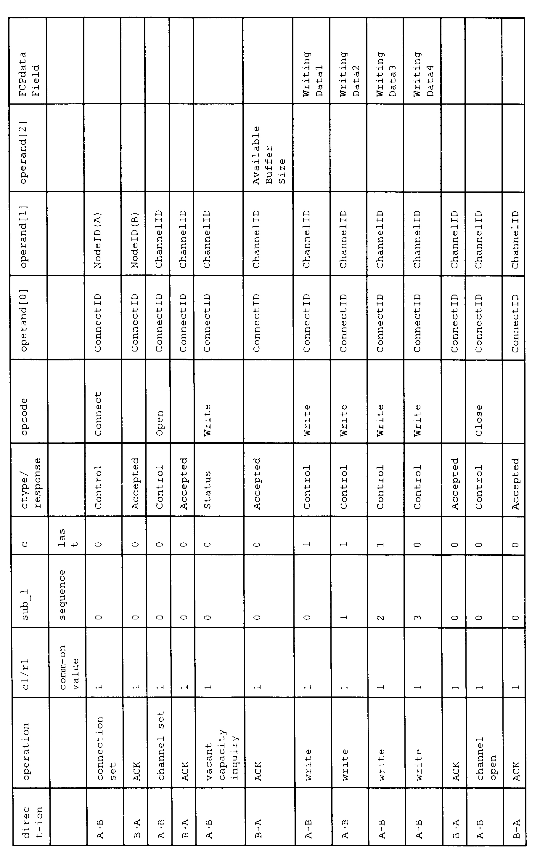
The sequence of operations for writing data from the
node A to the node B using the above-described commands is
explained by referring to Fig.21. It is assumed that the
data written in the node B is split into plural packets and
transmitted from the node A.
In the sequence of operations shown in Fig.21, a
connection is first set up between the nodes A and B and a
channel is established in the connection. The total
available area in the node B is then ascertained and
subsequently data is written in the node B using plural
COMMAND packets. The channel is then opened and the
connection between the nodes A and B is also opened. This
sequence of operations is explained in detail with
reference to Fig.21.
First, the node A requests a connection to the node B,
using a CONNECT command. At this time, the node A sends to
the node B a
COMMAND packet 21 in which the ID number
NodeID(A) of the node A and the ConnectID allocated to the
connection to be set up are stated in the operand field.
Specifically, the
command packet 21, whose fields are set
as shown in Table 1:
| field | c1 | sub_1 | c | ctype | opcode | operand[0] | operand [1] |
| set value | 1 | 0 | 0 | CONTROL | CONNECT | connectID | NodeID(A) |
is sent from the node A to the node B.
If the connection has been set up correctly by the
command packet 21, the node B returns to the node A a
response specifying that connection has been set up
correctly. At this time, the node b sends to the node A a
response packet 22 in which the ID number of the node B
NodeID(B) and the allocated ConnectID are stated in its
fields. Specifically, the response packet 22, whose fields
have been set as shown in Table 2:
| fields | r1 | sub_1 | c | response | operand[0] | operand[0] |
| set values | 1 | 0 | 0 | ACCEPTED | connectID | NodeID(B) |
is returned from the node B to the node A.
By the above exchange, the connection is set up
between the nodes A and B. If the connection has already
been set up between the nodes A and B, it is unnecessary to
make the exchange.
The node A then requests to the node B that the
channel be established using the OPEN command. At this
time, the node A sends to the node B a command packet 23 in
whose operand fields have been stated the connectID of the
connection in use and the channelID allocated to the
channel to be established. Specifically, the command packet
23, whose fields have been set as shown in Table 3:
| field | c1 | sub_1 | c | ctype | opcode | operand[0] | operand[0] |
| set values | 1 | 0 | 0 | CONTROL | OPEN | ConnectID | ConnectID |
is sent from the node a to the node B.
When a channel is established by the command packet
22, the node B returns to the node A a response specifying
that the channel has been established. At this time, the
node B sends to the node A a response packet 24 stating the
ConnectID of the connection in use and the allocated
ChannelID, Specifically, the response packet 24 whose
fields have been set as shown in table 4:
| field | r1 | sub_l | c | response | operand[0] | operand[1] |
| set values | 1 | 0 | 0 | ACCEPTED | ConnectID | ChannelID |
is sent from the node A to the node B.
By the above exchange, the connection is set up
between the nodes A and B. If the connection has already
been set up between the nodes A and B, it is unnecessary to
make the exchange.
The node A then of the node B the volume of the
available vacant area of the node B using the WRITE
command. Specifically, the command packet 25, whose fields
have been set as shown in Table 5:
| field | c1 | sub_l | c | ctype | opcode | opeerand[0] | operand[1] |
| set values | 1 | 0 | 0 | STATUS | WRITE | connectID | ChannelID |
is sent from the node A to the node B.
On accepting the command packet 25, the node B advises
the node A of volume of the available vacant area of the
node B. At this time, the node B sends to the node A a
response packet 26 in whose operand fields have been stated
the ConnectID of the connection in use, the ChannelID of
the channel in use and the volume of the available vacant
area of the node B AvailableBufferSize. Specifically, the
response packet 26, whose fields have been set as shown in
Table 6:
| field | r1 | sub_1 | c | response | operand[0] | operand[1] | operand[2] |
| set values | 1 | 0 | 0 | accepted | connectID | channelID | Available BufferSize |
is sent from the node B to the node A.
The node A then writes data in the node B using the
WRITE command. Since the data written in the node B is
split into
n fractions, the first data WritingDatal is
first sent. At this time, the node A sends to the node B a
command packet 27-1 in whose operand field have been stated
ConnectID of the connection in use and the ChannelID of the
channel in use and in a residual area of whose FCPdata
field has been stated the WritingDatal. Specifically, the
command packet 27-1 whose fields have been set as shown in
Table 7:
| field | c1 | sub_1 | c | ctype | opcode | operand [0] | operand [1] | residual area of FCPdata field |
| set values | 1 | 0 | 1 | write | contro | 1 | Connect ID | Channel ID | Writing Datal |
is sent from the node A to the node B.
The node A then sequentially transmits data split into
n fractions to the node B. At this time, the value of the
sub_I field is incremented by one for each command packet
in order to indicate the order of the command packets
corresponding to the divided data fractions to be sent.
Finally, the last one of the n-fractions of the data,
that is WritingDataN, is transmitted. At this time, the
node A sends to the node B a command packet in whose
operand fields have been stated the ConnectID of the
connection in use and ChannelID of the channel in use and
in the residual area of whose FCPdata field has been stated
the WritingDataN. Specifically, a command packet 27-n,
whose fields have been set as shown in Table 8, is sent
from the node A to the node B. At this time, the value of
the c field is set to ┌1┘ up to the command packet previous
to the command packet 27-n. However, at the command packet
27-n, the value of the c field is set to ┌0┘ in order to
specify that the command packet 27-n is the last one of the
packets of data for transmission split into
n fractions.
| field | c1 | sub_l | c | ctype | opcode | operand [0] | operand [1] | residual area of FCP data field |
| set values | 1 | n | 0 | control | write | Connect ID | Channel ID | Writing DataN |
When the data sent by the above command packets 27-1
to 27-n is correctly written in the node B, the latter then
returns to the node A a response indicating that the data
has been written correctly. At this time, the node B sends
to the node A response packet 28 stating in its operand
fields ConnectID of the connection in use and ChannelID of
the channel in use. Specifically, the response packet 28
whose fields have been set as shown in Table 9:
| field | r1 | sub_l | c | response | operand[0] | operand[1] |
| set values | 1 | 0 | 0 | accepted | ConnectID | ChannelID |
is returned from the node B to the node A.
The node A then requests the node B to open a channel
using a CLOSE command. At this time, the node A sends to
the node B a command packet 29 stating in its operand
fields ConnectID of the connection in use and ChannelID of
the channel desired to be opened. Specifically, the
command packet 29, whose fields are set as shown in Table
10:
| field | r1 | sub_l | c | response | opcode | operand[0] | operand[1] |
| set values | 1 | 0 | 0 | control | close | ConnectID | ChannelID |
is sent from the node A to the node B.
When the channel is opened by the command packet 29,
the node B returns to the node A a response indicating that
the channel has been opened. At this time, the node B sends
to the node A a response packet 30 stating in its operand
fields ConnectID of the connection in use and ChannelID of
the opened channel. Specifically, the response packet 30,
whose fields are set as shown in Table 11:
| field | r1 | sub_l | c | response | operand[0] | operand[1] |
| set values | 1 | 0 | 0 | ACCEPTED | ConnectID | ChannelID |
is returned from the node B to the node A.
By exchanging the command packet 29 and the response
packet 30, the channel used between the nodes A and B is
opened. Meanwhile, if it is unnecessary to open the
channel, exchange of the command packet 29 for opening the
channel and the response packet can be dispensed with.
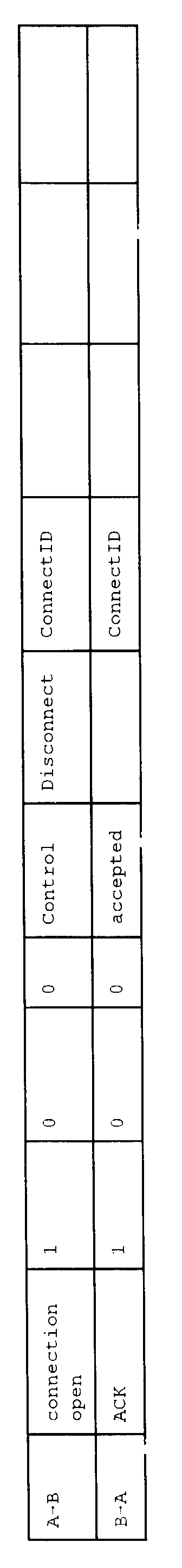
The node A then requests the node B to open the
connection using the DISCONNECT command. At this time, the
node A sends to the node B a command packet 31 stating in
its operand field ConnectID of the connection desired to be
opened. Specifically, the command packet 31, whose fields
have been set as shown in Table 12:
| field | c1 | sub_l | c | ctype | opcode | operand[0] |
| set values | 1 | 0 | 0 | control | disconnect | ConnectID |
is sent from the node A to the node B.
When the connection has been opened by the command
packet 31, the node B returns to the node A a response
specifying that the connection has been opened. At this
time, the node B returns to the node A a
response packet 32
stating ConnectID of the opened connection in its operand
field. Specifically, the
response packet 32 whose fields
have been set as shown in Table 13:
| field | r1 | sub_l | c | response | operand[0] |
| set values | 1 | 0 | 0 | accepted | ConnectID |
is returned from the node B to the node A.
By exchanging and the response packet 32, the
connection used between the nodes A and B is opened.
Meanwhile, if the connection need not be opened, there is
no necessity of exchanging the command packet 31 and the
response packet 32. for opening the connection.
The foregoing is the sequence of operations in
splitting the data from the node A into plural command
packets which are then written in the node B. This is
summarized in the following Table 14:
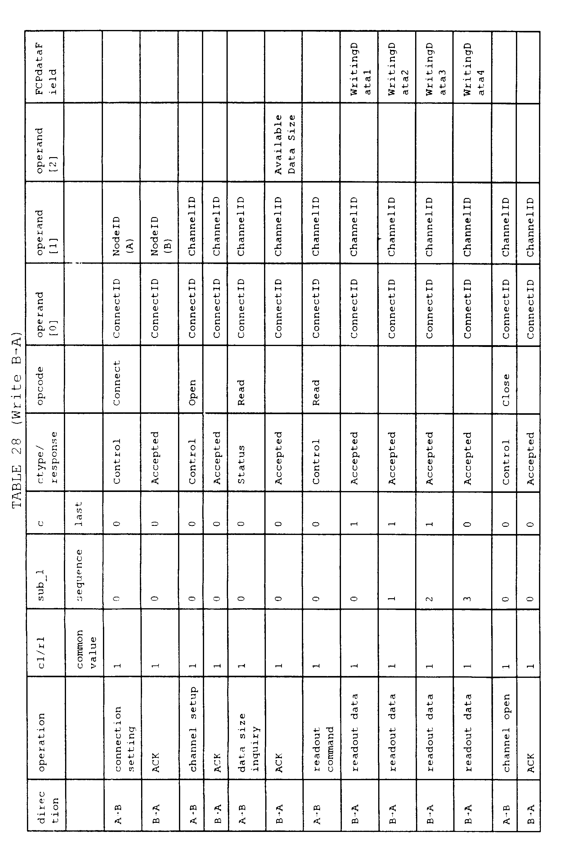
The sequence of operations for reading out data by
the node A from the node B using the above commands is
explained with reference to Fig.20. It is assumed that
the data read out from the node B is split into plural
packets and returned in this state from the node B to the
node A.
In the sequence shown in Fig.20, a connection is
first set up between the nodes A and B and a channel is
then established in the connection. After confirming the
readable data size, data is read out from the node B
using plural command packets. The channel is then opened
and the connection between the nodes A and B is opened.
This sequence of operations is now explained with
reference to Fig.20.
First, the node A requests a connection to the node
B using the CONNECT command. At this time, the node A
sends to the node B a
command packet 41 stating in its
operand field the ID number of the node A NodeID(A) and
ConnectID allocated to the connection to be set up.
specifically, the
command packet 41 whose fields are set
as shown in table 15:
| field | c1 | sub_l | c | ctype | opcode | operand[0] | operand[1] |
| set values | 1 | 0 | 0 | control | Connect | ConnectID | NodeID(A) |
is sent from the node A to the node B.
If the connection has been set up correctly by the
command packet 41, the node B returns to the node A a
response indicating that the connection has been set up
correctly. At this time, the node B sends to the node A
a response packet 42 stating in its operand field the
node ID number of the node B NodeID(B) and the allocated
ConnectID. Specifically, the response packet 42, whose
fields have been set as shown in Table 16:
| field | r1 | sub_l | c | response | operand[0] | operand[1] |
| set values | 1 | 0 | 0 | accepted | ConnectlD | NodeID(B) |
is returned form the node B to the node A.
By the above exchange, a connection is set up
between the nodes A and B. If the connection has already
been set up between the nodes A and B, it is unnecessary
to set up the connection newly.
The node A then requests the node B to establish the
channel using the OPEN command. At this time, the node A
sends to the node B a command packet 43 stating in its
operand field ConnectID of the connection in use and
ChannelID allocated to the channel to be established.
Specifically, the command packet 43, whose fields are set
as shown in Table 17:
| field | c1 | sub_l | c | ctype | opcode | operand[0] | operand[1] |
| set values | 1 | 0 | 0 | control | open | ConnectID | ChannelID |
is sent from the node A to the node B.
If the channel is established by the command packet
43, the node B returns to the node A a response
indicating that the channel has now been established. At
this time, the node B sends to the node A a response
packet 44 stating ConnectID of the connection in use and
allocated ChannelID in its operand fields. Specifically,
the response packet 44, whose fields are set as shown in
Table 18:
| field | r1 | sub_l | c | response | operand[0] | operand[1] |
| set values | 1 | 0 | 0 | accepted | ConnectID | ChannelID |
is returned from the node B to the node.
By the above exchange, a channel is established
between the nodes A and B. If the channel has already
been established between the nodes A and B, it is
unnecessary. to establish the channel newly.
The node A then inquires of the node B the data size
of readable data from the node B using the READ command.
At this time, the node A sends to the node B a command
packet 45 stating ConnectID of the connection in use and
ChannelID of the channel in use in the operand fields.
Specifically, the command packet 45, whose fields are set
as shown in Table 19:
| field | c1 | sub_l | c | ctype | opcode | operand[0] | operand[1] |
| set values | 1 | 0 | 0 | status | read | ConnectID | ChannelID |
is sent from the node A to the node B.
On reception of the command packet 45, the node B
apprizes the node A of the readable size of data read out
from the node B. At this time, the node-B sends to the
node A a response packet 46 stating in its operand field
ConnectID of the connection in use, ChannelID of the
channel in use and the data size AvailableDatasize of
data that can be read out from the node B. Specifically,
the response packet 46, whose fields are set as shown in
Table 20:
| field | c1 | sub_l | c | ctype | opcode | operand[0] | oprand[1] |
| set values | 1 | 0 | 0 | accepted | ConnectID | ChannelID | Available DataSize |
is sent from the node B to the node A.
The node A then requests the node B to read out data
using READ command. At this time, the node A sends a
command packet 47 stating ConnectID of the connection in
use and ChannelID of the channel in use in its operand
field. Specifically, the command packet 47, whose fields
are set as shown in Table 21:
| field | c1 | sub_l | c | ctype | opcode | operand[0] | operand[1] |
| set values | 1 | 0 | 0 | control | read | ConnectID | ChannelID |
is sent from the node a to the node B.
The node B then transmits the data requested by the
node A to the node A.
It is assumed that the data read out from the node B
is split into
n fractions which are sent to the node A.
Here, the first fractional data ReadingData1 is sent. At
this time, the node A sends to the node B a response
packet 48-1 stating ConnectID of the connection in use
and ChannelID of the channel in use in its operand field
and also stating ReadingData1 in the remaining area of
the FCPdata field. Specifically, the response packet 48-1,
whose fields are set as shown in Table 22:
| field | r1 | sub_l | c | response | operand[0] | operand[1] | remaining area of FCPdata field |
| set values | l | | 0 | 1 | accepted | ConnectID | ChannelID | Reading Datal |
is sent from the node A to the node B.
Similarly, n fractional data are sequentially
transmitted from the node B to the node A. At this time,
the value of the sub_l field is incremented by 1 for each
command packet in order to specify the sequence of the
response packets for transmitting the fractional data.
Finally, ReadingDataN, which is the trailing end one
of the
n fractional data, is transmitted. At this time,
the node B sends to the node A a response packet 48-n
stating ConnectID of the connection in use and ChannelID
of the channel in use in the operand field and stating
ReadingDataN in the remaining area of the FCPdata field.
Specifically, the response packet 48-n, whose fields are
set as shown in Table 23, is set from the node B to the
node A. The value of the c field is set to ┌1┘ up to the
command packet directly previous to the command packet
48-n and is set to ┌1┘ for the command packet 48-n in
order to specify that this command packet 48-n is the
trailing end one of the data packets of data for
transmission split into n fractions.
| field | r1 | sub_l | c | response | operand[0] | operand[1] | remaining area of FCPdata field |
| set values | 1 | n | 0 | accepted | ConnectID | ChannelID | reading DataN |
On completion of data readout from the node B, the
node A requests the node B to open the channel using the
CLOSE command. At this time, the node A sends to the node
B a command packet 49 stating ConnectID of the connection
in use and ChannelID of the channel to be opened in its
operand field. Specifically, the command packet 49, whose
fields are set as shown in Table 24:
| field | r1 | sub_l | c | ctype | opcode | operand[0] | operand[1] |
| set values | 1 | 0 | 0 | control | close | ConnectID | ChannelID |
is sent from the node A to the node B.
On opening the channel by the command packet 49, the
node B returns to the node A a response specifying that
the channel has been opened. At this time, the node B
sends a response packet 50 stating ConnectID of the
connection in use and ChannelID of the opened channel in
its operand field. Specifically, the response packet 50,
whose fields are set as shown in Table 25:
| field | r1 | sub_l | c | response | operand[0] | operand[1] |
| set values | 1 | 0 | 0 | accepted | ConnectID | ChannelID |
is returned from the node B to the node A.
By exchanging the command packet 49 and the response
packet 50, the channel used between the nodes A and B is
opened. Meanwhile, if the channel need no be opened,
there is no necessity of exchanging the command packet 49
for opening the connection and the response packet 50.
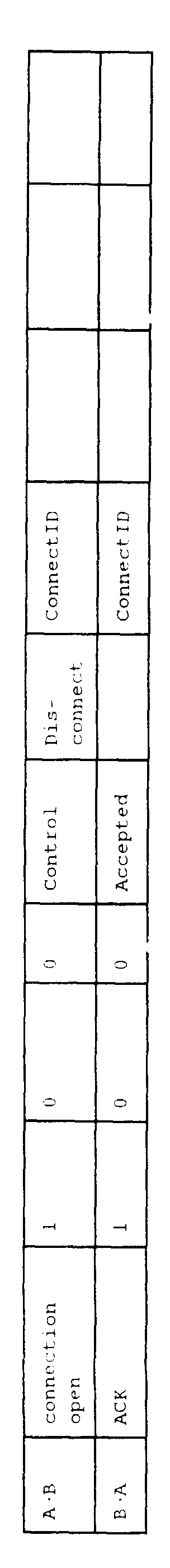
The node A then requests the node B to open the
connection using the DISCONNECT command. At this time,
the node A sends to the node B a command packet 51
stating ConnectID of the connection to be opened in its
operand field. Specifically, the command packet 51,
whose fields are set as shown in Table 26:
| field | c1 | sub_l | c | ctype | opcode | operand[0] |
| set values | 1 | 0 | 0 | control | disconnect | ConnectID |
is sent from the node A to the node B.
On opening the connection by the command packet 51,
the node B returns to the node A a response indicating
that the connection has been opened. At this time, the
node B sends to the node A a
response packet 52 stating
ConnectID of the opened connection in its operand field.
Specifically, the
response packet 52, whose fields are
set as shown in Table 27:
| field | r1 | sub_l | c | response | operand[0] |
| set values | 1 | 0 | 0 | accepted | ConnectID |
is returned from the node B to the node A.
By exchanging the command packet 51 and the response
packet 52, the channel used between the nodes A and B is
opened. Meanwhile, if the channel need not be opened,
there is no necessity of exchanging the command packet 51
for opening the connection and the response packet 52.
The foregoing is the sequence of operations used in
splitting data from the node B into plural command
packets and reading out the split data. This is
summarized in Table 28:
It should be noted that a recording medium in the
meaning of the present invention is not limited to any
specific type provided that the recording medium has
stored therein packets including command codes. The
recording medium according to the present invention
encompasses optical disc mediums, known as CD-ROMs,
magnetic disc mediums, such as floppy discs, semiconductor
devices, such as ROM, paper mediums stating codes signals
per se circulated on communication networks, typified by
Internet, electro-magnetic waves per se circulated as
electro-magnetic waves by radio communication, typified by
portable telephone, or any other mediums, without regard
to whether or not these mediums constitute physical
entities.
Although the preferred embodiments of the present
invention have been explained taking an example of the
IEEE 1394 bus, the present invention can be applied to
other than the IEEE 1394 bus. That is, the present
invention is applicable to data transmission/reception of
data which cannot be accommodated in a packet, in
addition to command transmission/reception, despite the
fact that the commands were conventionally assumed to be
sent by a sole packet.