EP0890848B1 - Multi-tuned single coil transmission line probe for nuclear magnetic resonance spectrometer - Google Patents
Multi-tuned single coil transmission line probe for nuclear magnetic resonance spectrometer Download PDFInfo
- Publication number
- EP0890848B1 EP0890848B1 EP98630034A EP98630034A EP0890848B1 EP 0890848 B1 EP0890848 B1 EP 0890848B1 EP 98630034 A EP98630034 A EP 98630034A EP 98630034 A EP98630034 A EP 98630034A EP 0890848 B1 EP0890848 B1 EP 0890848B1
- Authority
- EP
- European Patent Office
- Prior art keywords
- transmission line
- probe
- radio frequency
- junction point
- impedance
- Prior art date
- Legal status (The legal status is an assumption and is not a legal conclusion. Google has not performed a legal analysis and makes no representation as to the accuracy of the status listed.)
- Expired - Lifetime
Links
Images

Classifications
-
- G—PHYSICS
- G01—MEASURING; TESTING
- G01R—MEASURING ELECTRIC VARIABLES; MEASURING MAGNETIC VARIABLES
- G01R33/00—Arrangements or instruments for measuring magnetic variables
- G01R33/20—Arrangements or instruments for measuring magnetic variables involving magnetic resonance
- G01R33/28—Details of apparatus provided for in groups G01R33/44 - G01R33/64
- G01R33/32—Excitation or detection systems, e.g. using radio frequency signals
- G01R33/36—Electrical details, e.g. matching or coupling of the coil to the receiver
- G01R33/3628—Tuning/matching of the transmit/receive coil
- G01R33/3635—Multi-frequency operation
Definitions
- the present invention relates to probes for nuclear magnetic resonance (NMR) spectrometers and specifically to a capacitance tuned probe employing a single sample coil suitable for multiple radio frequency resonance experiments, wherein the tuning elements of the probe are remotely disposed from the magnetic field, connected to the sample coil by means of coaxial transmission lines.
- NMR nuclear magnetic resonance
- a high-intensity uniform magnetic field is generated within an extremely strong magnet. Inserted into the axial bore of the magnet is the sample to be analyzed, and the combination radio frequency transmitting and receiving sample coil.
- the sample coil is situated to generate an oscillating field with a component at right angles to the main magnetic field.
- the oscillating radio frequency field causes an oscillation in the alignment of the nuclear spins present in the sample undergoing analysis.
- the oscillation of the various chemical species within the magnet causes the emission of radio frequency signals, which are received by the sample coil and associated probe circuits.
- US-A-4 446 431 discloses an NMR spectrometer with a probe which comprises a sample coil connected to a double-tuned circuit means comprising a high frequency irradiation means and a low frequency irradiation means.
- the two frequencies have a ratio of about at least three to one or more and are in the radio frequency range.
- the high frequency irradiation means is connected to the sample coil through a transmission line means comprising a transmission line of a length of about one half of the high frequency wavelength.
- a preferred transmission line is a coaxial cable transmission line, more preferably a low-loss coaxial cable transmission line.
- the low frequency irradiation means is connected to the sample coil through the transmission line means through an inductor means connected to the transmission line at the point along the transmission line where the magnitude of the impedance for the high frequency irradiation is at or about a minimum.
- Journal of Magnetic Resonance 89 (1990) p. 620-626 discloses a multi-tuned single coil probe for a nuclear magnetic resonance spectrometer, comprising a coaxial transmission line network including an inner and an outer electrical conductor, a single sample coil for radio frequencies, said coil being coupled to said coaxial transmission line network, with four radio frequency input-output connectors coupled to said coaxial transmission line network via a network of suitable inductors and capacitors.
- the multi-tuned single coil transmission line probe of the present invention provides a high degree of efficiency for both the irradiation of samples and the detection of the induced nuclear magnetic resonance signals.
- the probe comprises a single sample coil connected to a multi-tuned circuit, including a coaxial line transmission network, and multiple radio frequency input-output means.
- the transmission network is preferably composed of copper pipe or tubing having sectional lengths proportional to the radio frequency wavelengths of the input-output means, and a large outer diameter, on the order of 5.08 cm (2 inches) or more for increased efficiency, reduced electrical resistance, and the internal placement of the tuning circuits.
- the inner and outer conductors of the coaxial transmission line are structured such that the ratio of the inner diameter of the outer tube to the outer diameter of the inner tube is approximately 3.59:1.
- the multiple radio frequency input-output means of the present embodiment are each adapted to a unique radio frequency in the range from 50 MHz to 500 MHz, however, additional lower frequencies are not excluded from the probe design.
- the unique radio frequency for each input-output means is separated from the frequency of the next nearest input-output means by not less than a 6% difference.
- Each input-output means is connected to the coaxial transmission line by a capacitive tuning and matching circuit composed of variable capacitors positioned inside the outer conductor of the coaxial transmission line.
- An important feature of the invention is the large number of radio frequency input-output means connected to the single sample coil via the coaxial line transmission network. This larger number reduces the chances for operator error during calibration by eliminating the need for the operator to remove the probe to change the radio frequencies at which the sample is being irradiated.
- Another important feature of the invention is the elimination of the need for the use of inductive tuning components, with the associated high radio frequency losses, for impedance matching purposes.
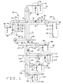
- FIG. 1 and 2 there is shown a circuit diagram of the multi-tuned NMR probe 20 of the present invention, configured for operation on six separate radio frequencies.
- a sample coil circuit 22, disposed within a magnet 24 and connected to an external transmission network 26 is employed to excite a sample 28 under analysis, detecting its magnetic resonance signature.
- the sample coil circuit 22 comprises a sample coil 30, connected between a coaxial line segment 32 of the transmission network 26 and electrical ground G. Connected in series between the sample coil 30 and the electrical ground G is a resistor 34 and fixed capacitor 36. To maintain a high degree of efficiency for the NMR probe, the magnitude of the resistor 34 corresponds to the inherent loss of the sample coil 30, as minimized through standard radio frequency techniques.
- the fixed capacitor 36 is used to provide an impedance for the sample coil 30, aiding in the tuning of individual probe frequencies.
- the optimum capacitance level for the fixed capacitor 36 is determined by analyzing the efficiency of the NMR probe 20 for each incorporated frequency, and selecting an optimum capacitance level resulting in the least amount of tuning interference over all the frequencies.
- a second fixed capacitor 38 is shown in Fig. 1 connected in parallel with the sample coil 30, between the segment 32 and electrical ground G.
- the fixed capacitor 38 represents the combination of the distributed capacitance and stray capacitance to ground of the sample coil 30.
- Radio frequency signals are transmitted to and from the sample coil circuit 22 by means of the transmission network 26.
- Each component of the transmission network 26 is a coaxial transmission line segment, having a length specifically selected to provide an impedance match for an individually tuned radio frequency.
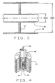
- Each coaxial transmission line comprises an inner tubular conductor 40 and outer tubular conductor 42, (Fig. 3) structured such that the ratio of the inner diameter IDOC of the outer conductor 42 to the outer diameter ODIC of the inner conductor 40 is approximately 3.59:1.
- the coaxial transmission lines are preferably composed of a copper tubing or pipes, which are essentially air dielectric since the inner conductor 40 is supported at a few points with Teflon® discs 44.
- the inner diameter of the outer coaxial conductor 42 must be of sufficient size so as to allow for the conventional tuning and coupling circuits described generally below to be located within the outer conductor 42.
- the preferred embodiment of the NMR probe 20 employs outer conductors 42 having a large outer diameters on the order of 5.08 cm (2 inches) or more to increase the NMR probe 20 efficiency and to reduce the electrical resistance of the transmission network 26.
- segment 32 connects the sample coil circuit 22 to the transmission network 26.
- the length L1 of segment 32 is calculated from standard transmission line equations using the value of the terminating impedance of the sample coil circuit 22 and the parameters of the transmission network 26 itself, such as radial dimensions, and composition. In practice, once the theoretical length of segment 32 is calculated, the exact length L1 is determined using standard radio frequency measurement techniques.
- a variable capacitor 46 is added internally to the segment 32, connecting the inner conductor 40 to the outer conductor 42 at a point of high impedance. The variable capacitor 46 is then tuned to adjust the signal impedance of the segment 32 such that a point of minimum impedance for the highest tuned frequency of the NMR probe 20 is exactly positioned at a junction point A in the transmission network 26.
- the highest frequency tuned by the present embodiment of the NMR probe 20 is the proton frequency of 500 MHz.
- points of minimum impedance for particular radio-frequencies on coaxial transmission lines repeat every one-half wavelength.
- the first occurrence of the minimum impedance point for the highest tuned frequency it is possible for the first occurrence of the minimum impedance point for the highest tuned frequency to be physically present within the bore 48 of the probe magnet 24, preventing its use as a junction point. In such situations, the first point of minimum impedance occurring external to the magnet bore 48 is employed as an alternate junction point.
- junction point A is positioned at the third minimum impedance point for the proton frequencies along segment 32.
- segment 32 Interconnected to segment 32 and the sample coil circuit 22 at junction point A, are coaxial transmission line segments 50, 52, and 54, each impedance matched to one or more tuned radio frequencies.
- Coaxial transmission line segment 50 along with a shunt element 56 connects junction point A with a radio-frequency input-output (I/O) circuit 58 suitable for proton irradiation.
- the proton I/O circuit 58 comprises a 500 MHz input-output port 60 adapted to a characteristic impedance, for example, 50 ohms, connected in series with a conventional tuning and coupling circuits comprising a variable capacitor 62 and a grounded variable capacitor 64.
- the shunt element 56 is positioned a length L2 along segment 50, at junction point B, approximately a quarter wavelength of the fluorine frequency from junction point A. Shunt element 56 acts as a radio frequency trap for the fluorine frequency, creating a very low impedance at junction point B for the fluorine frequency, and at the same time presenting a high impedance to the proton frequency.
- the length L3 of shunt element 56 is slightly longer than a quarter wavelength at the fluorine frequency, permitting internal variable capacitors 66 and 68 to be adjusted to meet the desired impedance conditions described above.
- segment 50 is selected such that the length from junction point B to the proton I/O circuit 58 permits reasonable values for variable capacitor 62 and grounded variable capacitor 64 to be used to tune and match to the desired 50 ohm impedance.
- two fixed capacitors 70 and 72 each valued at about 10 pico-farads increase the overall efficiency of the low frequency channels by isolating them from the proton I/O circuit 58 and the fluorine trap 56.
- Capacitor 70 is positioned on the inner coaxial conductor 40 adjacent to junction point A, capacitor 72 is positioned adjacent junction point B.
- coaxial transmission line segment 52 provides a connection between the transmission network 26 and a radio frequency input-output circuit 74 suitable for fluorine irradiation.
- the fluorine I/O circuit 74 comprises a 470 MHz input-output port 76 adapted to a characteristic impedance, for example, 50 ohms, connected in series with a conventional tuning and coupling circuit comprising a variable capacitor 78 and a grounded variable capacitor 80.
- the length L5 of segment 52 is selected such that it provides an impedance transformation of the impedance into segment 52 from junction point A, where it is capacitive, to the fluorine I/O circuit 74 to where it is inductive, and hence may be tuned and matched by reasonable values for capacitors 78 and 80.
- junction Point A The remaining coaxial transmission line segment connected to Junction Point A is segment 54, which serves as a connection link from the lower radio frequency channels to the sample coil circuit 22 via segment 32.
- the input impedance from junction point A to segment 54 must be high at the fluorine frequency to prevent fluorine signal power from being drained into segment 54, reducing the efficiency of the fluorine I/O circuit 74.
- the length L6 of segment 54, terminating at junction point C is a quarter wavelength at the fluorine frequency. Additionally, junction point C is maintained at a low impedance to the fluorine frequency by a shunt element 82 connected at junction point C.
- Shunt element 82 is a coaxial transmission line segment with a length L7 slightly less than a quarter wavelength at the fluorine frequency, and containing a variable capacitor 84 interconnecting the inner conductor 40 with the outer conductor 42.
- the variable capacitor 84 is adjusted to create a minimum impedance at junction point C as set forth above.
- junction point C is connected to junction point C and a fixed capacitor 88 connected to electrical ground G.
- the fixed capacitor 88 aids in maintaining the minimum impedance at junction point C, but is primarily used to tune the lower frequency channels connected to junction point C by segment 86.
- the capacitance of the fixed capacitor 88 affects the lengths of each subsequent coaxial transmission line segment used for lower radio frequencies in the transmission network 26.
- the length L8 of coaxial transmission line segment 86, terminating at junction point D, is selected to produce a minimum impedance at junction point D for the next lower radio frequency tuned on the NMR probe 20.
- a variable capacitor 90 contained within segment 86 permits the location of the next impedance minimum point to be electronically adjusted to a fine degree of precision along the length L8 of segment 86.
- the next lower radio frequency corresponds to that of phosphorous.
- a coaxial transmission line segment 92 provides a connection between junction point D on the transmission network 26 and a radio frequency input-output circuit 94 suitable for phosphorous irradiation.
- the phosphorous I/O circuit 94 comprises a 202 MHz input-output port 96 adapted to a characteristic impedance, for example, 50 ohms, connected in series witn a conventional tuning and coupling circuit comprising a variable capacitor 98 and a grounded variable capacitor 100.
- the length L9 of segment 92 is selected such that the impedance minimum for phosphorus at junction point D is transformed into an inductive impedance which can then be tuned and matched by reasonable values for the variable capacitors 98 and 100.
- junction point D is connected to junction point D and a fixed capacitor 104 connected to electrical ground.
- the fixed capacitor 104 aids in maintaining the minimum impedance at junction point D, but is primarily used to tune the lower frequency channels connected to junction point D by segment 102, much the same as fixed capacitor 88 tunes junction point C.
- the capacitance of fixed capacitor 104 similarly affects the lengths of each subsequent coaxial transmission line segment for lower radio frequencies in the transmission network 26.
- the length L10 of coaxial transmission line segment 102, terminating at junction point E, is selected to produce a minimum impedance at junction point E for the next lower radio frequency tuned on the NMR probe 20.
- a variable capacitor 106 contained within segment 102 permits the location of the next impedance minimum point to the electronically adjusted to a fine degree of precision along the length L10 of segment 102.
- the next lower radio frequency corresponds to that of carbon-13.
- a coaxial transmission line segment 108 provides a connection between junction point E on the transmission network 26 and a radio frequency input-output circuit 110 suitable for carbon-13 irradiation.
- the carbon-13 I/O circuit 110 comprises a 125 MHz input-output port 112 adapted to a characteristic impedance, for example, 50 ohms, connected in series with a conventional tuning and coupling circuit comprising a variable capacitor 114 and a grounded variable capacitor 116.
- the length L11 of segment 108 is selected such that the impedance minimum for carbon-13 at junction point E is transformed into an inductive impedance which can then be tuned and matched by reasonable values for the variable capacitors 114 and 116.
- junction point E is connected to junction point E.
- the fixed capacitor 120 aids in maintaining the minimum impedance at junction point E, but is primarily used to tune the lower frequency channels connected to junction point E by segment 118, much the same as fixed capacitor 104 tunes junction point D.
- the capacitance of fixed capacitor 120 affects the lengths of each subsequent coaxial transmission line segment for lower radio frequencies in the transmission network 26.
- the length L12 of coaxial transmission line segment 118, terminating at junction point F, is selected to produce a minimum impedance at junction point F for the next radio frequency tuned on the NMR probe 20.
- the next radio frequency corresponds to that of nitrogen-15. This is an example where the frequency of the next channel to add is not the next lowest frequency but is the next occurring impedance minima.
- a coaxial transmission line segment 122 provides a connection between junction point F on the transmission network 26 and a radio frequency input-output circuit 124 suitable for nitrogen-15 irradiation.
- the nitrogen-15 I/O circuit 124 comprises a 50 MHz input-output port 126 adapted to a characteristic impedance, for example, 50 ohms, connected in series with a conventional tuning and coupling circuit comprising a variable capacitor 128 and a grounded variable capacitor 130.
- the length L13 of segment 122 is selected such that the impedance minimum for nitrogen-15 at junction point F is transformed into an inductive impedance which can then be tuned and matched by reasonable values for the variable capacitors 128 and 130.
- a final coaxial transmission line segment 132 is connected to junction point F to provide connection to a radio frequency input-output circuit 134 suitable for oxygen-17 irradiation at 67.78 MHz, through a radio frequency I/O port 136.
- the length L14 of segment 132 is selected such that the variable capacitor 138, and the grounded variable capacitor 140 may be tuned and matched to provide a 50 ohm characteristic impedance match for the oxygen-17 I/O circuit 134.
- embodiments of the present invention may be constructed employing many different NMR frequencies by altering the quantity and impedance characteristics of the individual radio-frequency input-output means and the associated coaxial transmission line segment lengths.
- any channel or channels added may be changed to another frequency which is also lower than the channels iocated above it without altering the higher frequency channel settings. This makes possible, for example, the insertion of another group of nuclei for lower frequency channels at junction point E without altering the characteristics at junction points A-D.
- an embodiment of the present invention may be constructed suitable for Deuterium irradiation by altering the 67.78 MHz input-output port 136 to a 76.75 MHz input-output port.
- the length L14 of transmission line segment 132 would be recalculated to provide for the proper impedance matching by variable capacitors 138 and 140 as described above.
Abstract
Description
- This invention was made at least in part with funds from the Federal government, and the government therefore may have certain rights in the invention.
- The present invention relates to probes for nuclear magnetic resonance (NMR) spectrometers and specifically to a capacitance tuned probe employing a single sample coil suitable for multiple radio frequency resonance experiments, wherein the tuning elements of the probe are remotely disposed from the magnetic field, connected to the sample coil by means of coaxial transmission lines.
- In nuclear magnetic resonance machines, a high-intensity uniform magnetic field is generated within an extremely strong magnet. Inserted into the axial bore of the magnet is the sample to be analyzed, and the combination radio frequency transmitting and receiving sample coil. The sample coil is situated to generate an oscillating field with a component at right angles to the main magnetic field. The oscillating radio frequency field causes an oscillation in the alignment of the nuclear spins present in the sample undergoing analysis. The oscillation of the various chemical species within the magnet causes the emission of radio frequency signals, which are received by the sample coil and associated probe circuits.
- For some NMR analyses, particularly those involving solid sample materials, it is often desired to irradiate the sample with radio frequency fields of multiple frequencies at relatively high power levels, for example, in the 300 to 1000 watt range. It is important that a good coupling be achieved at all of the frequencies used. The usefulness and efficiency of prior art probes for this application is limited due to the size and magnetic restrictions for probe components, and the limited number of frequencies (usually only two or three) at which the samples may be irradiated without the operator removing and adjusting the probe settings. Each such removal and adjustment operation extends the time required to complete the sample analysis, and increases the chances of calibration and operator error.
- US-A-4 446 431 discloses an NMR spectrometer with a probe which comprises a sample coil connected to a double-tuned circuit means comprising a high frequency irradiation means and a low frequency irradiation means. The two frequencies have a ratio of about at least three to one or more and are in the radio frequency range. The high frequency irradiation means is connected to the sample coil through a transmission line means comprising a transmission line of a length of about one half of the high frequency wavelength. A preferred transmission line is a coaxial cable transmission line, more preferably a low-loss coaxial cable transmission line. The low frequency irradiation means is connected to the sample coil through the transmission line means through an inductor means connected to the transmission line at the point along the transmission line where the magnitude of the impedance for the high frequency irradiation is at or about a minimum.
- Journal of Magnetic Resonance 89 (1990) p. 620-626 discloses a multi-tuned single coil probe for a nuclear magnetic resonance spectrometer, comprising a coaxial transmission line network including an inner and an outer electrical conductor, a single sample coil for radio frequencies, said coil being coupled to said coaxial transmission line network, with four radio frequency input-output connectors coupled to said coaxial transmission line network via a network of suitable inductors and capacitors.
- The efficiency of prior art probes is additionally limited by their design characteristics. Traditionally, the desired radio frequencies were impedance matched to a particular value using standard, well known inductor techniques. However, while employing inductors is well known to generate impedance minima, inductors are characterized by high radio frequency losses, lowering the overall probe efficiency. Similar radio frequency losses result from each of the numerous interconnecting leads required between prior art probe components.
- Among the several objects and advantages of the present invention include:
- The provision of a new and improved probe as defined in claim 1 for a nuclear magnetic resonance (NMR) spectrometer in which the tuning elements are remotely connected to the sample coil via a coaxial transmission line having low radio frequency losses;
- The provision of the aforementioned probe which includes capacitive tuning elements integrated into the transmission line to reduce interconnection and inductor radio frequency losses;
- The provision of the aforementioned probe which positions the tuning elements outside the probe magnet and the associated magnetic field;
- The provision of the aforementioned probe which includes a single sample coil;
- The provision of the aforementioned probe which includes the capability to tune multiple radio frequencies on separate channels without the need for frequent probe recalibration;
- The provision of the aforementioned probe which includes the capacity to tune additional lower frequency channels without altering the settings of higher frequency channels;
- The provision of the aforementioned probe which includes the capability of operating on samples in potentially harmful environments;
- The provision of the aforementioned probe which includes the ability to operate on solid sample materials; and
- The provision of the aforementioned probe which includes robust components capable of withstanding high power levels.
-
- The multi-tuned single coil transmission line probe of the present invention provides a high degree of efficiency for both the irradiation of samples and the detection of the induced nuclear magnetic resonance signals. The probe comprises a single sample coil connected to a multi-tuned circuit, including a coaxial line transmission network, and multiple radio frequency input-output means. The transmission network is preferably composed of copper pipe or tubing having sectional lengths proportional to the radio frequency wavelengths of the input-output means, and a large outer diameter, on the order of 5.08 cm (2 inches) or more for increased efficiency, reduced electrical resistance, and the internal placement of the tuning circuits. The inner and outer conductors of the coaxial transmission line are structured such that the ratio of the inner diameter of the outer tube to the outer diameter of the inner tube is approximately 3.59:1.
- The multiple radio frequency input-output means of the present embodiment are each adapted to a unique radio frequency in the range from 50 MHz to 500 MHz, however, additional lower frequencies are not excluded from the probe design. The unique radio frequency for each input-output means is separated from the frequency of the next nearest input-output means by not less than a 6% difference. Each input-output means is connected to the coaxial transmission line by a capacitive tuning and matching circuit composed of variable capacitors positioned inside the outer conductor of the coaxial transmission line.
- An important feature of the invention is the large number of radio frequency input-output means connected to the single sample coil via the coaxial line transmission network. This larger number reduces the chances for operator error during calibration by eliminating the need for the operator to remove the probe to change the radio frequencies at which the sample is being irradiated. Another important feature of the invention is the elimination of the need for the use of inductive tuning components, with the associated high radio frequency losses, for impedance matching purposes.
- The foregoing and other objects, features, and advantages of the invention as well as presently preferred embodiments thereof will become more apparent from the reading of the following description in connection with the accompanying drawings.
- In the accompanying drawings which form part of the specification:
- Figure 1 is a detailed circuit diagram of a six-frequency-tuned embodiment of the multi-tuned single coil transmission line probe described herein.
- Figure 2 is a view similar to Fig. 1 in which the individual circuit elements have been omitted so that necessary measurements may be more clearly shown.
- Figure 3 is a cross sectional view of a coaxial transmission line segment of the NMR probe.
- Figure 4 is a cut away perspective view of a typical NMR sample coil and magnet assembly.
-
- Corresponding reference numerals will be used to indicate corresponding parts throughout the several figures of the drawings.
- The following detailed description illustrates the invention by way of example and not by way of limitation. The description will clearly enable one skilled in the art to make and use the invention, describes several embodiments, adaptations, variations, alternatives, and uses of the invention, including what we presently believe is the best mode of carrying out the invention.
- Referring to Figs. 1 and 2, there is shown a circuit diagram of the
multi-tuned NMR probe 20 of the present invention, configured for operation on six separate radio frequencies. Asample coil circuit 22, disposed within amagnet 24 and connected to anexternal transmission network 26 is employed to excite a sample 28 under analysis, detecting its magnetic resonance signature. Thesample coil circuit 22 comprises asample coil 30, connected between acoaxial line segment 32 of thetransmission network 26 and electrical ground G. Connected in series between thesample coil 30 and the electrical ground G is aresistor 34 andfixed capacitor 36. To maintain a high degree of efficiency for the NMR probe, the magnitude of theresistor 34 corresponds to the inherent loss of thesample coil 30, as minimized through standard radio frequency techniques. Similarly, thefixed capacitor 36 is used to provide an impedance for thesample coil 30, aiding in the tuning of individual probe frequencies. The optimum capacitance level for thefixed capacitor 36 is determined by analyzing the efficiency of theNMR probe 20 for each incorporated frequency, and selecting an optimum capacitance level resulting in the least amount of tuning interference over all the frequencies. - Included for computational purposes, but not as an added component, a second
fixed capacitor 38 is shown in Fig. 1 connected in parallel with thesample coil 30, between thesegment 32 and electrical ground G. Thefixed capacitor 38 represents the combination of the distributed capacitance and stray capacitance to ground of thesample coil 30. - Radio frequency signals are transmitted to and from the
sample coil circuit 22 by means of thetransmission network 26. Each component of thetransmission network 26 is a coaxial transmission line segment, having a length specifically selected to provide an impedance match for an individually tuned radio frequency. Each coaxial transmission line comprises aninner tubular conductor 40 and outertubular conductor 42, (Fig. 3) structured such that the ratio of the inner diameter IDOC of theouter conductor 42 to the outer diameter ODIC of theinner conductor 40 is approximately 3.59:1. The coaxial transmission lines are preferably composed of a copper tubing or pipes, which are essentially air dielectric since theinner conductor 40 is supported at a few points withTeflon® discs 44. Furthermore, the inner diameter of the outercoaxial conductor 42 must be of sufficient size so as to allow for the conventional tuning and coupling circuits described generally below to be located within theouter conductor 42. The preferred embodiment of theNMR probe 20 employsouter conductors 42 having a large outer diameters on the order of 5.08 cm (2 inches) or more to increase theNMR probe 20 efficiency and to reduce the electrical resistance of thetransmission network 26. - During normal operation of the
NMR probe 20, high voltages of several thousand volts for each channel used during a particular experiment will be present at thesample coil circuit 22. In connecting thesample coil circuit 22 to thetransmission network 26, connections capable of withstanding these voltage must be made. These connections must be made as short as possible to minimize radio-frequency losses in them and of sufficient size so as to carry large radio-frequency currents. The connections need to have smooth surfaces and large diameters to prevent the buildup of high electric field strengths that can cause corona discharge. - Accordingly,
segment 32 connects thesample coil circuit 22 to thetransmission network 26. The length L1 ofsegment 32 is calculated from standard transmission line equations using the value of the terminating impedance of thesample coil circuit 22 and the parameters of thetransmission network 26 itself, such as radial dimensions, and composition. In practice, once the theoretical length ofsegment 32 is calculated, the exact length L1 is determined using standard radio frequency measurement techniques. To accommodate the difficulty in cutting an exactly length of the copper pipe comprising the coaxial transmission line, avariable capacitor 46 is added internally to thesegment 32, connecting theinner conductor 40 to theouter conductor 42 at a point of high impedance. Thevariable capacitor 46 is then tuned to adjust the signal impedance of thesegment 32 such that a point of minimum impedance for the highest tuned frequency of theNMR probe 20 is exactly positioned at a junction point A in thetransmission network 26. - The highest frequency tuned by the present embodiment of the
NMR probe 20 is the proton frequency of 500 MHz. As is well known by those familiar with transmission lines, points of minimum impedance for particular radio-frequencies on coaxial transmission lines repeat every one-half wavelength. In some implementations of theNMR probe 20, it is possible for the first occurrence of the minimum impedance point for the highest tuned frequency to be physically present within thebore 48 of theprobe magnet 24, preventing its use as a junction point. In such situations, the first point of minimum impedance occurring external to the magnet bore 48 is employed as an alternate junction point. In Fig. 1, junction point A is positioned at the third minimum impedance point for the proton frequencies alongsegment 32. - Interconnected to
segment 32 and thesample coil circuit 22 at junction point A, are coaxialtransmission line segments - Coaxial
transmission line segment 50, along with ashunt element 56 connects junction point A with a radio-frequency input-output (I/O)circuit 58 suitable for proton irradiation. The proton I/O circuit 58 comprises a 500 MHz input-output port 60 adapted to a characteristic impedance, for example, 50 ohms, connected in series with a conventional tuning and coupling circuits comprising avariable capacitor 62 and a groundedvariable capacitor 64. - To provide a high impedance at junction point A towards the proton I/
O circuit 58 and to minimize power loss in that direction, theshunt element 56 is positioned a length L2 alongsegment 50, at junction point B, approximately a quarter wavelength of the fluorine frequency from junction pointA. Shunt element 56 acts as a radio frequency trap for the fluorine frequency, creating a very low impedance at junction point B for the fluorine frequency, and at the same time presenting a high impedance to the proton frequency. The length L3 ofshunt element 56 is slightly longer than a quarter wavelength at the fluorine frequency, permitting internalvariable capacitors - Finally, the overall length L4 of
segment 50 is selected such that the length from junction point B to the proton I/O circuit 58 permits reasonable values forvariable capacitor 62 and groundedvariable capacitor 64 to be used to tune and match to the desired 50 ohm impedance. Included onsegment 50, two fixedcapacitors O circuit 58 and thefluorine trap 56.Capacitor 70 is positioned on the innercoaxial conductor 40 adjacent to junction point A,capacitor 72 is positioned adjacent junction point B. - Functioning similar to
segment 50. coaxialtransmission line segment 52 provides a connection between thetransmission network 26 and a radio frequency input-output circuit 74 suitable for fluorine irradiation. The fluorine I/O circuit 74 comprises a 470 MHz input-output port 76 adapted to a characteristic impedance, for example, 50 ohms, connected in series with a conventional tuning and coupling circuit comprising avariable capacitor 78 and a groundedvariable capacitor 80. The length L5 ofsegment 52 is selected such that it provides an impedance transformation of the impedance intosegment 52 from junction point A, where it is capacitive, to the fluorine I/O circuit 74 to where it is inductive, and hence may be tuned and matched by reasonable values forcapacitors - The remaining coaxial transmission line segment connected to Junction Point A is
segment 54, which serves as a connection link from the lower radio frequency channels to thesample coil circuit 22 viasegment 32. The input impedance from junction point A tosegment 54 must be high at the fluorine frequency to prevent fluorine signal power from being drained intosegment 54, reducing the efficiency of the fluorine I/O circuit 74. To maintain the desired high impedance at the fluorine frequency, the length L6 ofsegment 54, terminating at junction point C, is a quarter wavelength at the fluorine frequency. Additionally, junction point C is maintained at a low impedance to the fluorine frequency by ashunt element 82 connected at junction pointC. Shunt element 82 is a coaxial transmission line segment with a length L7 slightly less than a quarter wavelength at the fluorine frequency, and containing avariable capacitor 84 interconnecting theinner conductor 40 with theouter conductor 42. Thevariable capacitor 84 is adjusted to create a minimum impedance at junction point C as set forth above. - Additionally connected to junction point C is the coaxial
transmission line segment 86 and a fixedcapacitor 88 connected to electrical ground G. The fixedcapacitor 88 aids in maintaining the minimum impedance at junction point C, but is primarily used to tune the lower frequency channels connected to junction point C bysegment 86. The capacitance of the fixedcapacitor 88 affects the lengths of each subsequent coaxial transmission line segment used for lower radio frequencies in thetransmission network 26. - The length L8 of coaxial
transmission line segment 86, terminating at junction point D, is selected to produce a minimum impedance at junction point D for the next lower radio frequency tuned on theNMR probe 20. Functioning similar tovariable capacitor 46, avariable capacitor 90 contained withinsegment 86 permits the location of the next impedance minimum point to be electronically adjusted to a fine degree of precision along the length L8 ofsegment 86. In the present embodiment shown in Fig. 1. the next lower radio frequency corresponds to that of phosphorous. - Operating similar to
segment 52, a coaxialtransmission line segment 92 provides a connection between junction point D on thetransmission network 26 and a radio frequency input-output circuit 94 suitable for phosphorous irradiation. The phosphorous I/O circuit 94 comprises a 202 MHz input-output port 96 adapted to a characteristic impedance, for example, 50 ohms, connected in series witn a conventional tuning and coupling circuit comprising avariable capacitor 98 and a groundedvariable capacitor 100. The length L9 ofsegment 92 is selected such that the impedance minimum for phosphorus at junction point D is transformed into an inductive impedance which can then be tuned and matched by reasonable values for thevariable capacitors - Additionally connected to junction point D is the coaxial transmission line segment 102 and a fixed
capacitor 104 connected to electrical ground. The fixedcapacitor 104 aids in maintaining the minimum impedance at junction point D, but is primarily used to tune the lower frequency channels connected to junction point D by segment 102, much the same as fixedcapacitor 88 tunes junction point C. The capacitance of fixedcapacitor 104 similarly affects the lengths of each subsequent coaxial transmission line segment for lower radio frequencies in thetransmission network 26. - The length L10 of coaxial transmission line segment 102, terminating at junction point E, is selected to produce a minimum impedance at junction point E for the next lower radio frequency tuned on the
NMR probe 20. Functioning similar tovariable capacitor 90, avariable capacitor 106 contained within segment 102 permits the location of the next impedance minimum point to the electronically adjusted to a fine degree of precision along the length L10 of segment 102. In the present embodiment shown in Fig. 1, the next lower radio frequency corresponds to that of carbon-13. - Operating similar to
segment 92, a coaxialtransmission line segment 108 provides a connection between junction point E on thetransmission network 26 and a radio frequency input-output circuit 110 suitable for carbon-13 irradiation. The carbon-13 I/O circuit 110 comprises a 125 MHz input-output port 112 adapted to a characteristic impedance, for example, 50 ohms, connected in series with a conventional tuning and coupling circuit comprising avariable capacitor 114 and a groundedvariable capacitor 116. The length L11 ofsegment 108 is selected such that the impedance minimum for carbon-13 at junction point E is transformed into an inductive impedance which can then be tuned and matched by reasonable values for thevariable capacitors - Additionally connected to junction point E is the coaxial
transmission line segment 118 and a fixedcapacitor 120 connected to electrical ground G. The fixedcapacitor 120 aids in maintaining the minimum impedance at junction point E, but is primarily used to tune the lower frequency channels connected to junction point E bysegment 118, much the same as fixedcapacitor 104 tunes junction point D. The capacitance of fixedcapacitor 120 affects the lengths of each subsequent coaxial transmission line segment for lower radio frequencies in thetransmission network 26. - The length L12 of coaxial
transmission line segment 118, terminating at junction point F, is selected to produce a minimum impedance at junction point F for the next radio frequency tuned on theNMR probe 20. In the present embodiment shown in Fig. 1, the next radio frequency corresponds to that of nitrogen-15. This is an example where the frequency of the next channel to add is not the next lowest frequency but is the next occurring impedance minima. - Operating similar to
segment 108, a coaxialtransmission line segment 122 provides a connection between junction point F on thetransmission network 26 and a radio frequency input-output circuit 124 suitable for nitrogen-15 irradiation. The nitrogen-15 I/O circuit 124 comprises a 50 MHz input-output port 126 adapted to a characteristic impedance, for example, 50 ohms, connected in series with a conventional tuning and coupling circuit comprising avariable capacitor 128 and a groundedvariable capacitor 130. The length L13 ofsegment 122 is selected such that the impedance minimum for nitrogen-15 at junction point F is transformed into an inductive impedance which can then be tuned and matched by reasonable values for thevariable capacitors - As seen in Fig. 1, a final coaxial
transmission line segment 132 is connected to junction point F to provide connection to a radio frequency input-output circuit 134 suitable for oxygen-17 irradiation at 67.78 MHz, through a radio frequency I/O port 136. The length L14 ofsegment 132 is selected such that thevariable capacitor 138, and the groundedvariable capacitor 140 may be tuned and matched to provide a 50 ohm characteristic impedance match for the oxygen-17 I/O circuit 134. - Although the invention has been illustrated by a single embodiment employing six separately tuned radio frequencies, it is not limited thereto. Changes and modifications of the illustrated embodiment can be made which do not constitute departure from the scope of the invention. In particular, embodiments of the present invention may be constructed employing many different NMR frequencies by altering the quantity and impedance characteristics of the individual radio-frequency input-output means and the associated coaxial transmission line segment lengths.
- As can be seen from the modular nature of the design of the
NMR probe 20, any channel or channels added may be changed to another frequency which is also lower than the channels iocated above it without altering the higher frequency channel settings. This makes possible, for example, the insertion of another group of nuclei for lower frequency channels at junction point E without altering the characteristics at junction points A-D. - More particularly, an embodiment of the present invention may be constructed suitable for Deuterium irradiation by altering the 67.78 MHz input-
output port 136 to a 76.75 MHz input-output port. Correspondingly, the length L14 oftransmission line segment 132 would be recalculated to provide for the proper impedance matching byvariable capacitors - In view of the above, it will be seen that the several objects of the invention are achieved and other advantageous results are obtained. As various changes could be made in the above constructions without departing from the scope of the invention, it is intended that all matter contained in the above description or shown in the accompanying drawings shall be interpreted as illustrative and not in a limiting sense.
Claims (18)
- A multi-tuned single coil probe (20) for a nuclear magnetic resonance spectrometer, said probe comprising:a coaxial transmission line network (26), the network including an outer electrical conductor (42) and a coaxial inner electrical conductor (40);a single sample coil (30) for radio frequencies, said coil (30) being electrically coupled to said coaxial transmission line network (26) at a first junction point (A) thereof by means of a first coaxial connecting transmission line segment (32);and a multiplicity of radio frequency input-output connectors (60,76,96,112,126,136);a first input-output connector (60) being provided with a first capacitive tuning circuit (58) adapted uniquely to a first resonance frequency, e.g. that of protons, and electrically coupled via a second coaxial connecting transmission line segment (50) to the first junction point (A) of the transmission line network, the first junction point (A) having a minimum impedance for the first resonance frequency along the first connecting transmission line segment (32), the length of the second connecting transmission line segment (50) being such that it provides an impedance transformation of the impedance minimum at the first junction point (A) to an inductive impedance for the first frequency at said first capacitive tuning circuit (58);the second connecting transmission line segment (50) providing a second junction point (B) for connecting a first radio frequency trap circuit (56) for a second resonance frequency, e.g. that of fluorine, lower than the first resonance frequency, thus providing a high impedance for the second resonance frequency at the first junction point (A) towards said second connecting transmission line segment (50);a second input-output connector (76) being provided with a second capacitive tuning circuit (74) adapted uniquely to the second resonance frequency and electrically coupled via a third coaxial connecting transmission line segment (52) to the first junction point (A) of the transmission line network; the length of the third connecting transmission line segment (52) being such that it provides an impedance transformation of the capacitive impedance at the first junction point (A) to an inductive impedance for the second resonance frequency at said second capacitive tuning circuit (74);a first coaxial transmission line segment (54) of said transmission line network being provided between the first junction point (A) and a third junction point (C), the length of said first segment (54) being such that the input impedance from the first junction point (A) to said first segment (54) is high at the second resonance frequency, a second radio frequency trap circuit (82) for the second resonance frequency being connected at the third junction point (C) to provide a minimum impedance for the second resonance frequency at the third junction point (C);a second coaxial transmission line segment (86) of said transmission line network being provided between the third junction point (C) and a fourth junction point (D), the length of the said second segment (86) being such that it provides a minimum impedance for a third resonance frequency, e.g. that of phosphorous, lower than the second resonance frequency, at the fourth junction point (D);a third input-output connector (96) being provided with a third capacitive tuning circuit (94) adapted uniquely to said third resonance frequency and electrically coupled via a fourth connecting transmission line segment (92) to the fourth junction point (D) of the transmission line network, the length of said fourth connecting transmission line segment (92) being such that it provides an impedance transformation of the impedance minimum at the fourth junction point (D) to an inductive impedance for the third resonance frequency at said third capacitive tuning circuit (94);the transmission line network being modular such that additional channels for further resonance frequencies, lower than the above-defined resonance frequencies, may be coupled to the network after the fourth junction point (D) in a manner similar to the third input-output connector, without altering the characteristics at the fourth and previous junction points.
- The probe of claim 1 in which each of said capacitive tuning circuits is remotely disposed from said sample coil and the magnetic field, of said spectrometer.
- The probe of claim 1 in which each of said capacitive tuning circuits includes a series connected variable capacitor and a grounded variable capacitor.
- The probe of claim 3 in which each of said capacitive tuning circuits are contained within the outer electrical conductor of said coaxial transmission line network.
- The probe of claim 3 in which said capacitive tuning circuits can adjust said input-output radio frequencies by = 1-2%
- The probe of claim 1 in which said inner and outer electrical conductors of the coaxial transmission line network are composed of cylindrical conducting tubes, the ratio of the inner diameter of the outer conducting tube to the outer diameter of the inner conducting tube being approximately 3.59:1.
- The probe of claim 6 in which said outer conducting tube has a outer diameter greater than 5.08 cm (two inches).
- The probe of claim 6 in which said inner and outer conducting tubes are made of a highly conductive material.
- The probe of claim 8 in which said inner and outer conducting tubes are made of copper.
- The probe of claim 6 in which said coaxial transmission line network contains a low loss dielectric material.
- The probe of claim 10 in which said low loss dielectric material is air.
- The probe of claim 1, in which said resonance frequencies are separated by no less than 6% differences.
- The probe of claim 1, in which said resonance frequencies range from 50 MHz to 500 MHz.
- The probe of claim 1 in which said plurality of radio frequency input-output connectors include:a radio frequency input-output connector adapted to the proton radio frequency of approximately 500.0 MHz;a radio frequency input-output connector adapted to the fluorine radio frequency of approximately 470.0 MHz;a radio frequency input-output connector adapted to the phosphorus radio frequency of approximately 202.0 MHz;a radio frequency, input-output connector adapted to the carbon-13 radio frequency of approximately 125.0 MHz; anda radio frequency input-output connector adapted to the nitrogen-15 radio frequency of approximately 50.0 MHz.
- The probe of claim 14 in which said plurality of radio frequency input-output connectors further include a radio frequency input-output connector adapted to the deuterium radio frequency of approximately 76.75 MHz.
- The probe of claim 14 in which said plurality of radio frequency input-output connectors further include a radio frequency input-output connector adapted to the oxygen-17 radio frequency of approximately 67.78 MHz.
- The probe of claim 1 wherein the coaxial transmission line network further includes a plurality of capacitive tuning elements interconnecting the inner and outer electrical conductors, said capacitive tuning elements affecting the location of said minimum impedance points.
- The probe of claim 17 wherein the interconnecting tuning elements are variable capacitors.
Applications Claiming Priority (2)
| Application Number | Priority Date | Filing Date | Title |
|---|---|---|---|
| US889922 | 1997-07-10 | ||
| US08/889,922 US5861748A (en) | 1997-07-10 | 1997-07-10 | Multi-tuned single coil transmission line probe for nuclear magnetic resonance spectrometer |
Publications (2)
| Publication Number | Publication Date |
|---|---|
| EP0890848A1 EP0890848A1 (en) | 1999-01-13 |
| EP0890848B1 true EP0890848B1 (en) | 2005-06-01 |
Family
ID=25395995
Family Applications (1)
| Application Number | Title | Priority Date | Filing Date |
|---|---|---|---|
| EP98630034A Expired - Lifetime EP0890848B1 (en) | 1997-07-10 | 1998-07-03 | Multi-tuned single coil transmission line probe for nuclear magnetic resonance spectrometer |
Country Status (5)
| Country | Link |
|---|---|
| US (1) | US5861748A (en) |
| EP (1) | EP0890848B1 (en) |
| JP (1) | JPH1172547A (en) |
| AT (1) | ATE297020T1 (en) |
| DE (1) | DE69830363D1 (en) |
Families Citing this family (13)
| Publication number | Priority date | Publication date | Assignee | Title |
|---|---|---|---|---|
| US6081120A (en) * | 1998-05-20 | 2000-06-27 | Shen; Gary G | Universal-multi-layered, multi-tuned RF probe for MRI and MRS |
| DE19923294C1 (en) | 1999-05-21 | 2001-02-15 | Bruker Analytik Gmbh | Sample head in which two different nuclear types are excited has high frequency line bridged on half the length with a resonance element |
| DE10019990C2 (en) * | 2000-04-22 | 2002-04-04 | Bruker Analytik Gmbh | Probe head for nuclear magnetic resonance measurements |
| JP3886764B2 (en) * | 2001-04-10 | 2007-02-28 | 日本電子株式会社 | Double tuning circuit and probe of nuclear magnetic resonance apparatus |
| WO2003058283A1 (en) * | 2001-12-31 | 2003-07-17 | The Johns Hopkins University School Of Medicine | Mri tunable antenna and system |
| JP2005520658A (en) | 2002-03-21 | 2005-07-14 | コーニンクレッカ フィリップス エレクトロニクス エヌ ヴィ | Combiner / splitter device for MRI system |
| FR2871891B1 (en) * | 2004-06-18 | 2006-09-01 | Bruker Biospin Sa Sa | MULTIFREQUENCIAL POWER SUPPLY CIRCUIT AND PROBE AND NMR SPECTROMETER COMPRISING SUCH A CIRCUIT |
| FR2871892B1 (en) * | 2004-06-18 | 2006-09-01 | Bruker Biospin Sa Sa | POWER SUPPLY CIRCUIT OF A COIL AND PROBE AND NMR SPECTROMETER COMPRISING SUCH A CIRCUIT |
| US7187176B2 (en) * | 2005-02-08 | 2007-03-06 | Bruker Biospin Corp. | NMR probe circuit with nodal impedance bridge |
| DE102006030640B4 (en) * | 2005-07-15 | 2018-05-09 | Jeol Ltd. | Nuclear magnetic resonance probe |
| US7352185B1 (en) * | 2006-11-22 | 2008-04-01 | Varian, Inc. | Multi-functional NMR probe |
| US9829550B2 (en) * | 2012-12-27 | 2017-11-28 | General Electric Company | Multi-nuclear receiving coils for magnetic resonance imaging (MRI) |
| EP3589966A1 (en) | 2017-03-01 | 2020-01-08 | ScanMed, LLC | Dual tuned mri resonator, coil package, and method |
Family Cites Families (16)
| Publication number | Priority date | Publication date | Assignee | Title |
|---|---|---|---|---|
| US2908858A (en) * | 1952-08-08 | 1959-10-13 | Varian Associates | Decoupling means for electrical circuits |
| US3372331A (en) * | 1965-01-25 | 1968-03-05 | Varian Associates | Gyromagnetic spectrometer having a tapered dielectric transition between a coaxial line and a helix structure |
| US3434043A (en) * | 1966-02-14 | 1969-03-18 | Varian Associates | Nuclear magnetic resonance probe apparatus having double tuned coil systems for spectrometers employing an internal reference |
| US3402346A (en) * | 1966-04-22 | 1968-09-17 | Varian Associates | Coaxial receiver coil and capacitor structure for probes of uhf gyromagnetic spectrometers |
| US3795855A (en) * | 1971-12-08 | 1974-03-05 | Cyclotron Corp | Magnetic resonance probe system |
| US3858112A (en) * | 1973-09-20 | 1974-12-31 | Nippon Electric Varian Ltd | A receiver circuit including a crystal resonator for nuclear magnetic resonance signals of two different frequencies |
| GB1544272A (en) * | 1975-02-04 | 1979-04-19 | Jeol Ltd | Nuclear magnetic resonance apparatus |
| US4129822A (en) * | 1975-04-24 | 1978-12-12 | Traficante D | Wide-band nuclear magnetic resonance spectrometer |
| US4095168A (en) * | 1977-02-22 | 1978-06-13 | Varian Associates, Inc. | Rf pick-up coil circuit for a wide tuning range nuclear magnetic resonance probe |
| US4093910A (en) * | 1977-02-22 | 1978-06-06 | Varian Associates, Inc. | Nuclear magnetic resonance pick-up circuit for control of resonance conditions |
| US4093911A (en) * | 1977-02-22 | 1978-06-06 | Varian Associates, Inc. | Nuclear magnetic resonance spectrometer employing an improved resonance signal gating circuit |
| US4446431A (en) * | 1981-08-24 | 1984-05-01 | Monsanto Company | Double-tuned single coil probe for nuclear magnetic resonance spectrometer |
| US4792759A (en) * | 1987-07-29 | 1988-12-20 | Elscint Ltd. | Multi-frequency surface probe |
| JPH01293858A (en) * | 1988-05-20 | 1989-11-27 | Toshiba Corp | Rf coil apparatus |
| US5675254A (en) * | 1993-06-02 | 1997-10-07 | The Board Of Trustees Of The University Of Illinois | Double-resonance MRI coil |
| EP0803069B1 (en) * | 1995-11-14 | 2004-03-17 | Koninklijke Philips Electronics N.V. | Coaxial cable for use in magnetic resonance apparatus |
-
1997
- 1997-07-10 US US08/889,922 patent/US5861748A/en not_active Expired - Lifetime
-
1998
- 1998-07-03 AT AT98630034T patent/ATE297020T1/en not_active IP Right Cessation
- 1998-07-03 EP EP98630034A patent/EP0890848B1/en not_active Expired - Lifetime
- 1998-07-03 DE DE69830363T patent/DE69830363D1/en not_active Expired - Lifetime
- 1998-07-10 JP JP10195340A patent/JPH1172547A/en active Pending
Also Published As
| Publication number | Publication date |
|---|---|
| US5861748A (en) | 1999-01-19 |
| ATE297020T1 (en) | 2005-06-15 |
| DE69830363D1 (en) | 2005-07-07 |
| JPH1172547A (en) | 1999-03-16 |
| EP0890848A1 (en) | 1999-01-13 |
Similar Documents
| Publication | Publication Date | Title |
|---|---|---|
| EP0890848B1 (en) | Multi-tuned single coil transmission line probe for nuclear magnetic resonance spectrometer | |
| US4594566A (en) | High frequency rf coil for NMR device | |
| KR890000411B1 (en) | Mutual inductance nmr rf coil maching device | |
| US4691163A (en) | Dual frequency surface probes | |
| US4887039A (en) | Method for providing multiple coaxial cable connections to a radio-frequency antenna without baluns | |
| EP0073614B1 (en) | Double-tuned single coil probe for nuclear magnetic resonance spectrometer | |
| US7397246B2 (en) | Electrically symmetric NMR coils with a plurality of windings connected in series | |
| US5424645A (en) | Doubly broadband triple resonance or quad resonance NMR probe circuit | |
| EP1710596B1 (en) | NMR probe circuit with nodal impedance bridge | |
| US4987370A (en) | Rf quadrature coil system for an MRI apparatus | |
| JP2748016B2 (en) | Double tuning circuit for distributed concentrated capacitance observation coil | |
| JP2904858B2 (en) | Nuclear magnetic resonance tomography system | |
| US5166621A (en) | Multi-resonant nmr coils | |
| EP0518896B1 (en) | Series/parallel double-tuned nmr coils | |
| US5162739A (en) | Balanced multi-tuned high-power broadband coil for nmr | |
| Gonord et al. | Parallel‐plate split‐conductor surface coil: Analysis and design | |
| US6175237B1 (en) | Center-fed paralleled coils for MRI | |
| EP0579473B1 (en) | Tunable RF probe for use in NMR spectroscopy experiments and method of tuning | |
| JP3914735B2 (en) | NMR probe for multiple resonance | |
| Brondeau et al. | Flexible Fourier multinuclear magnetic resonance spectrometer | |
| JP4156646B2 (en) | NMR probe for multiple resonance | |
| Stensgaard | Planar quadrature coil design using shielded-loop resonators | |
| JPH10314139A (en) | Magnetic resonance imaging device | |
| Tang et al. | Double-resonance circuit for nuclear magnetic resonance spectroscopy | |
| Moore et al. | Power efficient double‐resonance NMR probe for electromagnets |
Legal Events
| Date | Code | Title | Description |
|---|---|---|---|
| PUAI | Public reference made under article 153(3) epc to a published international application that has entered the european phase |
Free format text: ORIGINAL CODE: 0009012 |
|
| AK | Designated contracting states |
Kind code of ref document: A1 Designated state(s): AT BE CH CY DE DK ES FI FR GB GR IE IT LI LU MC NL PT SE |
|
| AX | Request for extension of the european patent |
Free format text: AL;LT;LV;MK;RO;SI |
|
| 17P | Request for examination filed |
Effective date: 19990205 |
|
| AKX | Designation fees paid |
Free format text: AT BE CH CY DE DK ES FI FR GB GR IE IT LI LU MC NL PT SE |
|
| 17Q | First examination report despatched |
Effective date: 20040128 |
|
| GRAP | Despatch of communication of intention to grant a patent |
Free format text: ORIGINAL CODE: EPIDOSNIGR1 |
|
| GRAS | Grant fee paid |
Free format text: ORIGINAL CODE: EPIDOSNIGR3 |
|
| GRAA | (expected) grant |
Free format text: ORIGINAL CODE: 0009210 |
|
| AK | Designated contracting states |
Kind code of ref document: B1 Designated state(s): AT BE CH CY DE DK ES FI FR GB GR IE IT LI LU MC NL PT SE |
|
| PG25 | Lapsed in a contracting state [announced via postgrant information from national office to epo] |
Ref country code: NL Free format text: LAPSE BECAUSE OF FAILURE TO SUBMIT A TRANSLATION OF THE DESCRIPTION OR TO PAY THE FEE WITHIN THE PRESCRIBED TIME-LIMIT Effective date: 20050601 Ref country code: LI Free format text: LAPSE BECAUSE OF FAILURE TO SUBMIT A TRANSLATION OF THE DESCRIPTION OR TO PAY THE FEE WITHIN THE PRESCRIBED TIME-LIMIT Effective date: 20050601 Ref country code: IT Free format text: LAPSE BECAUSE OF FAILURE TO SUBMIT A TRANSLATION OF THE DESCRIPTION OR TO PAY THE FEE WITHIN THE PRE;WARNING: LAPSES OF ITALIAN PATENTS WITH EFFECTIVE DATE BEFORE 2007 MAY HAVE OCCURRED AT ANY TIME BEFORE 2007. THE CORRECT EFFECTIVE DATE MAY BE DIFFERENT FROM THE ONE RECORDED.SCRIBED TIME-LIMIT Effective date: 20050601 Ref country code: FI Free format text: LAPSE BECAUSE OF FAILURE TO SUBMIT A TRANSLATION OF THE DESCRIPTION OR TO PAY THE FEE WITHIN THE PRESCRIBED TIME-LIMIT Effective date: 20050601 Ref country code: ES Free format text: LAPSE BECAUSE OF FAILURE TO SUBMIT A TRANSLATION OF THE DESCRIPTION OR TO PAY THE FEE WITHIN THE PRESCRIBED TIME-LIMIT Effective date: 20050601 Ref country code: CH Free format text: LAPSE BECAUSE OF FAILURE TO SUBMIT A TRANSLATION OF THE DESCRIPTION OR TO PAY THE FEE WITHIN THE PRESCRIBED TIME-LIMIT Effective date: 20050601 Ref country code: BE Free format text: LAPSE BECAUSE OF FAILURE TO SUBMIT A TRANSLATION OF THE DESCRIPTION OR TO PAY THE FEE WITHIN THE PRESCRIBED TIME-LIMIT Effective date: 20050601 Ref country code: AT Free format text: LAPSE BECAUSE OF FAILURE TO SUBMIT A TRANSLATION OF THE DESCRIPTION OR TO PAY THE FEE WITHIN THE PRESCRIBED TIME-LIMIT Effective date: 20050601 |
|
| REG | Reference to a national code |
Ref country code: GB Ref legal event code: FG4D |
|
| REG | Reference to a national code |
Ref country code: CH Ref legal event code: EP |
|
| REG | Reference to a national code |
Ref country code: IE Ref legal event code: FG4D |
|
| PG25 | Lapsed in a contracting state [announced via postgrant information from national office to epo] |
Ref country code: LU Free format text: LAPSE BECAUSE OF NON-PAYMENT OF DUE FEES Effective date: 20050703 Ref country code: CY Free format text: LAPSE BECAUSE OF FAILURE TO SUBMIT A TRANSLATION OF THE DESCRIPTION OR TO PAY THE FEE WITHIN THE PRESCRIBED TIME-LIMIT Effective date: 20050703 |
|
| PG25 | Lapsed in a contracting state [announced via postgrant information from national office to epo] |
Ref country code: IE Free format text: LAPSE BECAUSE OF NON-PAYMENT OF DUE FEES Effective date: 20050704 |
|
| REF | Corresponds to: |
Ref document number: 69830363 Country of ref document: DE Date of ref document: 20050707 Kind code of ref document: P |
|
| PG25 | Lapsed in a contracting state [announced via postgrant information from national office to epo] |
Ref country code: MC Free format text: LAPSE BECAUSE OF NON-PAYMENT OF DUE FEES Effective date: 20050731 |
|
| PG25 | Lapsed in a contracting state [announced via postgrant information from national office to epo] |
Ref country code: SE Free format text: LAPSE BECAUSE OF FAILURE TO SUBMIT A TRANSLATION OF THE DESCRIPTION OR TO PAY THE FEE WITHIN THE PRESCRIBED TIME-LIMIT Effective date: 20050901 Ref country code: GR Free format text: LAPSE BECAUSE OF FAILURE TO SUBMIT A TRANSLATION OF THE DESCRIPTION OR TO PAY THE FEE WITHIN THE PRESCRIBED TIME-LIMIT Effective date: 20050901 Ref country code: GB Free format text: LAPSE BECAUSE OF NON-PAYMENT OF DUE FEES Effective date: 20050901 Ref country code: DK Free format text: LAPSE BECAUSE OF FAILURE TO SUBMIT A TRANSLATION OF THE DESCRIPTION OR TO PAY THE FEE WITHIN THE PRESCRIBED TIME-LIMIT Effective date: 20050901 |
|
| PG25 | Lapsed in a contracting state [announced via postgrant information from national office to epo] |
Ref country code: DE Free format text: LAPSE BECAUSE OF FAILURE TO SUBMIT A TRANSLATION OF THE DESCRIPTION OR TO PAY THE FEE WITHIN THE PRESCRIBED TIME-LIMIT Effective date: 20050902 |
|
| PG25 | Lapsed in a contracting state [announced via postgrant information from national office to epo] |
Ref country code: PT Free format text: LAPSE BECAUSE OF FAILURE TO SUBMIT A TRANSLATION OF THE DESCRIPTION OR TO PAY THE FEE WITHIN THE PRESCRIBED TIME-LIMIT Effective date: 20051103 |
|
| NLV1 | Nl: lapsed or annulled due to failure to fulfill the requirements of art. 29p and 29m of the patents act | ||
| REG | Reference to a national code |
Ref country code: CH Ref legal event code: PL |
|
| PLBE | No opposition filed within time limit |
Free format text: ORIGINAL CODE: 0009261 |
|
| STAA | Information on the status of an ep patent application or granted ep patent |
Free format text: STATUS: NO OPPOSITION FILED WITHIN TIME LIMIT |
|
| REG | Reference to a national code |
Ref country code: IE Ref legal event code: MM4A |
|
| 26N | No opposition filed |
Effective date: 20060302 |
|
| GBPC | Gb: european patent ceased through non-payment of renewal fee |
Effective date: 20050901 |
|
| EN | Fr: translation not filed | ||
| PG25 | Lapsed in a contracting state [announced via postgrant information from national office to epo] |
Ref country code: FR Free format text: LAPSE BECAUSE OF NON-PAYMENT OF DUE FEES Effective date: 20050731 |
|
| PG25 | Lapsed in a contracting state [announced via postgrant information from national office to epo] |
Ref country code: FR Free format text: LAPSE BECAUSE OF NON-PAYMENT OF DUE FEES Effective date: 20050601 |