EP0895197B1 - Method for monitoring installations with mechanical components - Google Patents
Method for monitoring installations with mechanical components Download PDFInfo
- Publication number
- EP0895197B1 EP0895197B1 EP97810550A EP97810550A EP0895197B1 EP 0895197 B1 EP0895197 B1 EP 0895197B1 EP 97810550 A EP97810550 A EP 97810550A EP 97810550 A EP97810550 A EP 97810550A EP 0895197 B1 EP0895197 B1 EP 0895197B1
- Authority
- EP
- European Patent Office
- Prior art keywords
- model
- determined
- value
- values
- state
- Prior art date
- Legal status (The legal status is an assumption and is not a legal conclusion. Google has not performed a legal analysis and makes no representation as to the accuracy of the status listed.)
- Expired - Lifetime
Links
Images


Classifications
-
- G—PHYSICS
- G05—CONTROLLING; REGULATING
- G05B—CONTROL OR REGULATING SYSTEMS IN GENERAL; FUNCTIONAL ELEMENTS OF SUCH SYSTEMS; MONITORING OR TESTING ARRANGEMENTS FOR SUCH SYSTEMS OR ELEMENTS
- G05B23/00—Testing or monitoring of control systems or parts thereof
- G05B23/02—Electric testing or monitoring
- G05B23/0205—Electric testing or monitoring by means of a monitoring system capable of detecting and responding to faults
- G05B23/0218—Electric testing or monitoring by means of a monitoring system capable of detecting and responding to faults characterised by the fault detection method dealing with either existing or incipient faults
- G05B23/0243—Electric testing or monitoring by means of a monitoring system capable of detecting and responding to faults characterised by the fault detection method dealing with either existing or incipient faults model based detection method, e.g. first-principles knowledge model
- G05B23/0254—Electric testing or monitoring by means of a monitoring system capable of detecting and responding to faults characterised by the fault detection method dealing with either existing or incipient faults model based detection method, e.g. first-principles knowledge model based on a quantitative model, e.g. mathematical relationships between inputs and outputs; functions: observer, Kalman filter, residual calculation, Neural Networks
-
- G—PHYSICS
- G07—CHECKING-DEVICES
- G07C—TIME OR ATTENDANCE REGISTERS; REGISTERING OR INDICATING THE WORKING OF MACHINES; GENERATING RANDOM NUMBERS; VOTING OR LOTTERY APPARATUS; ARRANGEMENTS, SYSTEMS OR APPARATUS FOR CHECKING NOT PROVIDED FOR ELSEWHERE
- G07C3/00—Registering or indicating the condition or the working of machines or other apparatus, other than vehicles
Definitions
- the invention relates to a method for monitoring systems with mechanical, in particular hydromechanical, components.
- the document DE-C1-42 43 882 describes a method for monitoring a technical process using sensors for recording monitoring variables to be measured and parameters describing the process. This known method is characterized by the fact that after a normal state check and a check for completeness in the parameter space when new operating states for the respective monitoring variable occur, an individual model is restarted.
- the method should enable a reliable and early detection of malfunctions and be suitable for industrial applications.
- the method should be suitable for monitoring such systems or components which are operated at variable operating points.
- the method should allow a simple assessment of the operating state of the components. With the method, it should also be possible, even temporally slowly progressive changes, as z. B. caused by wear to be recognized. In addition, it should allow the process to detect trends for the further operation of the components.
- the problem solving method for monitoring systems with mechanical, especially hydromechanical, components that are operable at variable operating points is characterized by the features of the independent claim.
- the method according to the invention thus comprises the following steps:
- measured values are recorded in each case at predefinable time intervals for a defined set of state variables.
- the measurements acquired at different operating points during an upstream modeling phase in which the system operates in trouble-free operation are used to construct a model for the performance of the components, the input variables of the model being at least a part of the set of state variables and the output values being a model value for at least one of the state variables.
- a respective residual is determined.
- the model is optimized by determining model parameters such that a model error that can be determined from the residuals becomes minimal.
- at least one monitoring variable is determined at predetermined time intervals, which is independent of the current operating point. The time course of the monitored variable is used to assess the wear in the components and / or to detect malfunctions.
- the method according to the invention uses a monitoring variable which is independent of the respective current operating point, that is, fluctuations in the measured values for the state variables which are based solely on changes in the operating point do not lead to significant changes in the monitored variable.
- the method thus takes into account the mutual influence between the state variables at varying operating points.
- this means that the monitoring method according to the invention does not work with fixed threshold values for specific state variables, but that the threshold values are adapted to the respective current operating state.
- This allows a very reliable and early detection of both malfunction and slowly progressive changes, such as caused by wear.
- the triggering of false alarms and the "overlooking" of malfunctions, eg. B. in partial load operation occurs in the inventive method practically no longer on This is particularly advantageous in economic and safety aspects. Reliable monitoring helps to avoid unnecessary system downtime and significantly reduce maintenance costs.
- the monitoring quantity is independent of the current operating point, it results for them, as long as the system or the components disturbance and work wear-free, a substantially constant time value. As soon as there are disturbances or wear-related changes in the components, the monitored variable deviates from its constant value. Thus, by means of a graphical representation of the monitored variable as a function of time, a deviation from the normal operating state can be recognized in a very simple manner.
- the models determined at different times are preferably stored in the evaluation and storage device together with parameters which are representative of the quality of the respective model. This makes it possible, even with hindsight, to reconstruct the temporal evolution of the state variables. It is particularly advantageous that it is possible to dispense with a permanent storage of all recorded measured values and only a greatly reduced data set, namely in each case the model parameters or quantities from which they can be determined, as well as the parameters must be stored to later a reconstruction of To allow history.
- the parameters can z.
- the respective current model is optimized by means of the evaluation and storage device by calculating a respective residual for the associated state variable for the measured values acquired since the last update of the model by comparing them with the corresponding model values, and the model parameters of the current one Model are determined so that the determinable from the residuals model error is minimal.
- the model is always updated to reconstruct the most recent readings as well as possible, thus providing the best possible representative of the component to be monitored at all times. If malfunctions occur, they are intentionally incorporated into the model.
- the monitoring is advantageously carried out in this procedure as follows:
- At least one reference working point is fixed.
- the evaluation and storage device determines the associated model value as a nominal value for the corresponding state variable after each update of the model for the fixed reference working point by means of the respective current model.
- the time course of the nominal value is used to assess the wear in the components and / or to detect malfunctions.
- the monitoring quantity is the time course of the Nominal value resulting from the fixed reference working point and the current model. If no changes (malfunctions, wear) occur in the component to be monitored, no significant changes in the model parameters are made even when the model is updated. Consequently, the nominal value for the fixed reference operating point is also essentially constant over time. On the other hand, if changes occur in the components, this will cause the model parameters to change during the update. However, this normally also changes the nominal value, which is determined by means of the respectively current model for the fixed reference working point. Based on the change in the nominal value over time, changes in the components can thus be detected very easily. In addition, the rate of change of the nominal value may indicate whether the change in the components is due to a malfunction or wear.
- this process management also makes it possible to detect trends for the future operation of the components from the temporal course of the nominal value.
- the inventive method will be explained below with exemplary character with reference to a hydroelectric power plant with turbines.
- the hydroelectric power station is a representative example of a system to be monitored and the turbines serve as an example for the hydromechanical components of the plant. It is understood that the invention is not limited to such cases.
- the components may also be other turbomachines such as pumps or other mechanical systems such as steam turbines, steam boilers, compressors, generators, motors, transmissions.
- the systems in which such components are integrated can also be, for example, heating systems, locomotives, weaving machines or plasma spraying systems.
- state variables such directly or indirectly detectable quantities that are useful for characterizing the operating state of the component or the system or have an influence on the operating state.
- state variable includes the following quantities: power, pressure before and after the turbine, flow rate of the water, temperature of the water, speed of the turbine, temperature of the cooling medium, temperature in the generator, temperatures in Shaft bearings or seals, sound emissions, vibrations, blade positions, etc.
- operating point or “operating point” is meant that operating state in which the component or the system is currently operating.
- Each combination of state variables that can be realized with the component or system corresponds to one operating point.
- the totality of possible operating points is referred to as operating range.
- the operating point of the component or the system can be specified by the operating personnel by setting directly influenceable state variables to the desired value. For example, if the turbine is operating in part-load mode, it operates at a different operating point than in full-load operation.
- the plant 1 to be monitored is, for example, a hydroelectric power plant which contains turbines 2 as hydromechanical components. Since it is sufficient for the understanding, only one of the turbines 2 is symbolically indicated in FIG. Of course, usually more than one turbine 2 are provided in the system 1.
- a plurality of sensors 31, 32, 33,..., 3 n are provided for the metrological detection of state variables x 1 , x 2 , x 3 ,..., X n . Not all state variables have to be measured directly at the component 2, but also state variables at other parts of the plant can be measured, such as For example, the pressure of the water in the pressure line.
- state variables x 1 , x 2 , x 3 ,..., X n which are detected metrologically, depends on the type of system or component to be monitored. It is the experience of the skilled person to choose the appropriate state variables for the respective application.
- the sensors 31-3n transmit the data measured by them via signal lines 41, 42, 43,..., 4n, for example feeder optical lines, to an evaluation and storage device 5, where the data, if appropriate after conditioning or further processing, are measured values get saved.
- measured values x 1t , x 2t , x 3t ,..., X nt are respectively measured at predeterminable time intervals, for example every minute or every 10 minutes, by means of the sensors 31-3n for the set X of state variables recorded and stored in the evaluation and storage unit.
- the index t is equivalent to a run index, which indexes the temporally successive measured values.
- a model A for the operating behavior of the component 2 is created and evaluated.
- at least one monitoring variable which is independent of the current operating point, is determined at predefinable time intervals.
- the monitoring size in particular their time course is graphically represented by means of an output unit 6.
- the wear can be assessed and malfunctions can be detected. With wear doing business-related, usually slowly progressive changes are meant, for example in the shaft bearing or in the shaft seal of the turbine 2 and z. B.Dracks in lines or contamination of filters.
- Malfunctions may be, for example, failures or malfunctions of one of the sensors 31-3n or the actuators monitored by them (eg valves, control flaps) or faults in the system 1 or component 2, such as changes in vibrations or overheating of bearings or seals ,
- a warning device 7 for triggering an alarm.
- This warning device is activated if the monitored variable leaves a predefinable normal range.
- the alarm can be done, for example, visually and / or acoustically.
- the model A is a model which is obtained directly from experimental data, that is to say from the measured values x it recorded by the sensors 31-3n for the state variables x i .
- the modeling phase refers to a time-limited period of operation of the component 2 or the system 1, during which the system 1 operates in normal, ie trouble-free operation.
- the choice of modeling phase may be based on experience.
- the modeling phase is chosen to be so long that it comprises several different operating points from the operating range of component 2.
- measured values x it are collected for the state variables x i . These measured values x it therefore refer to several different operating points. Since the time interval of the measured value acquisition, that is to say the time between the measurement t and the measurement t + 1, can be relatively short, it may be advantageous to temporally average a plurality of temporally successive measured values for a state variable x i , or else to combine them with known statistical methods , for example by forming correlation matrices. In order to make this clear, the index T is used instead of the index t to indicate that the corresponding value can also represent the combination of several individual values. So z. For example, the measured values will be denoted by x iT in the future.
- At least one of the state variables x i is selected for which a model value y i is determined by means of the model A.
- As input variables of the model A at least a part of the set X of the state variables x i is used.
- the model A can be configured in a similar manner in such a way that its output variables comprise model values for more than one of the state variables x i .
- the state variable to be modeled in the exemplary embodiment described here is that with the index n, that is to say the output variable of the model is the model value y n for the state variable x n .
- measured values are therefore available for m times or time intervals.
- X * T see FIG.
- the m sets X T of measured values provide m determinative equations for the n model parameters a i . Since, as a rule, the number m of the sets of measured values is greater than the number n of the model parameters a i , the system of the determination equations is overdetermined. However, sufficient mathematical methods are known in order to determine the best possible values for the model parameters a i by means of the determination equations. Examples of suitable methods are the Equalization Calculation Method, the least squares method, the Singular Value Decomposition (SVD) method or the Principal Component Analysis (PCA). Since such methods are well known, they will not be explained in detail here.
- step 101 see FIG.
- a model error ⁇ is determined in step 102, which is a measure of the goodness of the model is.
- the model error ⁇ can be, for example, the normalized sum of the squares of the residuals.
- the model A is optimized until the model error ⁇ is minimal or falls below a predetermined limit. When this is achieved, model A is sufficiently good for monitoring (step 104).
- the creation and optimization of the model A can take place in only one step or in several steps.
- the system of the determination equations for the model parameters a i can be solved so that the resulting values for the model parameters a i already represent an optimized solution.
- model A creation of the model A and its optimization in several successive steps, ie the model A is first created, resulting in initial values for the model parameters, and then the model parameters are optimized in one or more iterative steps until the model error is minimal.
- Such an iterative procedure is usually necessary if the determinative equations for the model parameters do not exist solve analytically, z. For example, if neural networks are used as the model structure.
- Model A takes into account the current operating point.
- each measured value set is evaluated individually or the measured value sets are each over a period of time, for. As a day, collected and then averaged or summarized otherwise. For example, correlations or cross-correlations can also be determined.
- the model value y n is then determined from the measured values for the state variables x 1 , x 2 ,..., X n-1 by means of the model A.
- the monitored variable is transmitted to the output unit 6, where the time course of the monitored variable is preferably graphically, z. B. on a monitor.
- the monitoring size regardless of the current operating point, in time substantially constant. If a malfunction occurs, such as a failure of a sensor or overheating, this means that the model value, which indeed describes the normal operation, deviates more strongly from the actual measured value. Consequently, the monitored variable changes, which is very easily recognizable in its graphical representation. Usually, the occurrence of malfunctions leads to a temporally rapid change in the monitored variable.
- threshold values for the monitoring variable which limit the normal range of the monitored variable. If the threshold values are exceeded, activation of the warning device 7 causes an alarm, z. As an optical and / or acoustic signal, triggered or given a warning. Since the monitored variable is independent of the current operating point, such threshold values for the monitored variable are synonymous with flexible ones respective operating point adapted thresholds for the state variables.
- the threshold value for the monitoring variable can be chosen to be equal to or slightly larger than the largest of the residuals r 1 , r 2 ,... R m of the modeling phase.
- model structure for the model A can be other than the described linear static.
- the model structure may be a nonlinear one in which z. B. enter into products of the state variables. It is also possible a linear dynamic model structure z.
- all state variables x i are used as input variables, the value of this state variable being taken into account in the determination of the model value for the state variable x nT at an earlier point in time, x nT-1 .
- a model structure is used which is linear in the model parameters a i , because then the model parameters a i can normally be determined analytically.
- the index "u” is used in the following to mark the chronological order of the determined or recorded quantities (measured values, model values, models, residuals). So z. B. x iu the measured value, which is detected at a certain, designated by "u" time for the state variable x i and x iu + 1 the measured value of the same state variable x i is detected in the next measurement. As already mentioned above, the measured values, which are recorded, for example, every few minutes, can first be measured over a predefinable time period, eg. As a day, collected and then averaged and / or different, z. B. are summarized by formation of cross-correlations before the further process steps take place.
- x iu denotes the measurement averaged or summarized over this period denoted by u. This means that it is not differentiated in the following whether each recorded measured value set is evaluated individually, or whether a temporal averaging over several sets of measured values takes place. This difference is immaterial to understanding.
- the model A is first of all based on created and optimized the measured values acquired in the modeling phase.
- the following explanations therefore only refer to the operation of Appendix 1 after the modeling phase.
- a set of measured values x 1u , x 2u ,..., X nu for the set of state variables x 1 , x 2 ,..., X n is detected at predeterminable time intervals (step 201).
- the model A is updated at predeterminable time intervals by means of the evaluation and storage device 5, that is, as will be explained further below, in each case a current model M u is determined (step 205).
- a nominal value s nu for the state variable x n is determined for at least one fixed reference working point (step 206), which serves as a monitoring variable and is transmitted to the output unit 6 (step 207).
- the respective current model M u is always evaluated at the same reference operating point, irrespective of which operating point the system 1 or the component 2 is currently operating.
- This fixed reference working point which is defined by fixed values for the state variables x i , is preferably selected such that it lies approximately in the middle of the operating range of the system 1 or the component 2, for example. B. at the best point, or in the vicinity of a working point at which the system 1 or the component 2 often works or is operated.
- the determination and optimization of the respective current model M u can, for example, be carried out in a manner similar to that described above with reference to the generation of the model A from the measured values x iT of the modeling phase is described (see Fig. 1). That is, the update is a new determination of the model based on the set of measurements x 1u , x 2u , ... x nu .
- the model value y nu for the state variable x n is determined with the aid of the last current model M u-1 or with the help of the newly determined model.
- the residual r nu x nu -y nu is formed, which is the difference between the actual measured value x nu and the model value y nu .
- this residual r nu is minimized or, if several residuals are determined, a model error that can be determined from the residuals, eg. For example, the normalized sum of the squares of the residuals is minimized.
- the creation and optimization of the current model M u may be done in one step.
- the associated model parameters of the model M u-1 Before the last current model N is changed u-1 and the model is re-calculated, the associated model parameters of the model M u-1, and a characteristic quantity which is representative of the quality of this model M u-1, for example, correlation matrices and / or estimated variances of measurement noise.
- the older models whose model parameters and model uncertainties or qualities are stored, in particular in a weighted manner, are taken into account.
- a preferred realization of this incorporation of older models is explained below with reference to the flow chart in FIG. 3.
- a model M u * is created and optimized in step 203 ( eg analogous to the front described), which model M u * is based only on those measured values x 1u , x 2u , ..., x nu , which have been recorded since the last update.
- the symbol "*" is thus intended to indicate that only the measured values x 1u , x 2u , ..., x nu , which were determined in the period of time indicated by u, are used to create this model M u *.
- M u-1 * designates the model for the production of which the measurement values x 1 (u-1) , x 2 (u-1) ,..., X n (u ) recorded in the period of time indicated by (u-1) -1) can be used, etc.
- step 204 the model M u * is stored in the evaluation and storage device 5 (FIG. 1) together with parameters which are representative of its quality, for example correlation matrices and / or estimated variances of the measurement noise.
- the current model M u is then determined, which takes into account the older models M u-1 *, M u-2 *,..., For example as the sum of the form :.
- M u M u * + ⁇ M u - 1 * + ⁇ 2 M u - 2 * + ...
- ⁇ denotes a weighting factor or a forgetting factor.
- the weighting or forgetting factor ⁇ can be determined, for example, from the parameters which are stored together with the models M u-1 *, M u-2 *,...
- the current model M u After the current model M u has been determined and optimized, it is evaluated at the reference working point (step 206) and thus the nominal value s nu is determined as the monitoring variable and transmitted to the output unit 6 (FIG. 1).
- the respective current model M takes into account and the older models - that is, the history - because in the determination of the model M u-1 walked the models N U 1 * and M U-2, where u in M -2 models M u-2 * and M u-3 , etc.
- This variant has the advantage of requiring very little storage space, because the entire history (temporal evolution) is always described by a single model.
- the updating for determining the respective current model M u takes place regularly at predefinable time intervals, for example once a day.
- the monitoring quantity is not a difference between measured value and model value, but the nominal value s nu .
- This is the model value that is for the fixed reference working point from the respective current model M u . Consequently, even with this procedure, the monitoring variable s nu is independent of the current operating point. It always refers to the fixed reference working point. In other words, the monitoring quantity s nu indicates what value the state variable x n would have if the system 1 or the component 2 were operating at the reference operating point. It is obvious that the monitoring quantity s nu is substantially constant over time, as long as the plant 1 or the component 2 operates in normal operation.
- the model is updated regardless of whether a malfunction has occurred or not. If a change (fault, sensor failure, wear) occurs in the system 1 or component 2 to be monitored, this change will be incorporated into the current model M u during the update. Consequently, the current model M u then no longer represents the normal operation, but the changed by disturbance and / or wear operation. If the current model is now evaluated at the reference working point, the result is a nominal value s nu , which deviates from that of normal operation. Thus, in the graphical representation of the monitored variable as a function of time shows a deviation from the constant behavior. Again, malfunctions usually result in a temporally relatively rapid change in the monitored variable, while slowly progressive changes, such as those caused by wear, cause a comparatively slower and continuous change in the time course of the monitored variable s nu .
- a particular advantage of this kind of monitoring lies in the fact that it is also possible to identify or determine trends for the further operation of the components 2 or the system 1. This will be explained using the example of the wear of a seal. If the seal wears continuously, for example, this leads to a continuous increase in the time course of the monitored variable. Since the monitoring quantity always refers to the same reference operating point, it is thus possible to predict how long the seal will still be functional. As a result, maintenance work can be planned much better and more efficiently, and it is much less likely to cause unexpected and uneconomic business failures. For this reason too, the maintenance and operating costs of systems for industrial applications can be considerably reduced by the method according to the invention.
- an error isolation is also carried out, that is to say the error which has occurred is localized as well as possible.
- the aim of this fault isolation is to locate as precisely as possible that state variable or sensor 31-3n, which is responsible for ensuring that the deviation from normal operating behavior has occurred. If, for example, a storage temperature serves as the monitoring variable, then an abnormality z. B. on the one hand by a malfunction of the associated Sensors are caused on the other hand, but also by a malfunction in another area of the component or the system, eg. For example, by an inadmissible increase in the flow rate or by a malfunction of the sensor that detects the flow rate.
- the fault isolation is preferably carried out as follows:
- n 4 state variables x 1 , x 2 , x 3 , x 4 are detected metrologically and, as described above, the model A for the operating behavior or the current model M u is determined.
- the model dimension which corresponds to the dimension of the hypersurface spanned by the n-dimensional performance model of the n state variables, is three in this example.
- Such a sub-model is characterized by the fact that its model dimension is at least one lower than the model dimension of the model A or the current model M u .
- two-dimensional partial models are used, ie the model dimension of the partial models is two.
- the following submodels can be determined: m1 (x 1, x 2, x 3); m2 (x 1, x 2, x 4); m3 (x 1, x 3, x 4); m4 (x 2 , x 3 , x 4 )
- b 0 , b 1 and b 2 designate model parameters.
- the state variable x 4 is no longer included in the submodel m1.
- the state variable x 3 no longer enters the submodel m2
- the state variable x 2 no longer enters into the submodel m3
- the State variable x 1 is no longer included in submodel m4.
- the submodels m1-m4 which of the state variables x i serve as input variables and which as output variables.
- the partial model m1 it is possible to calculate the state variable x 1 from the state variables x 2 and x 3 , or to calculate the state variable x 2 from the state variables x 1 and x 3 , or the state variable x 3 from the state variables x 1 and x 2 to calculate.
- the partial models m2, m3 and m4 it is possible to calculate the state variable x 1 from the state variables x 2 and x 3 , or to calculate the state variable x 2 from the state variables x 1 and x 3 from the state variables x 1 and x 2 to calculate.
- the partial models m2, m3 and m4 it is possible to calculate the state variable x 1 from the state variables x 2 and x 3 , or to calculate the state variable x 2 from the state variables x 1 and x 2 to calculate.
- values are now determined for the state variables x 1 , x 2 , x 3 , x 4 , which are referred to as reconstructed values.
- a reconstruction error is determined for each of the submodels m 1-m 4, which is representative of how well the reconstructed values determined by the associated submodel match match the measured values. If the reconstruction error is greater than a predefinable threshold value, the associated submodel is assessed as faulty, otherwise it is not faulty.
- the thresholds for the reconstruction errors can be, for example, based on the residuals, the z. As determined in the modeling phase set.
- the submodels are divided into two classes: erroneous and non-defective. Based on the combinations of state variables x i that lead to defective submodels, and the combinations of state variables x i that are not faulty Submodels lead, then can isolate the faulty state variable.
- a fault liability of the state variable x 2 or of the sensor 32 leads to the fact that only the partial model, into which x 2 does not enter, namely m 3 , is judged not to be faulty.
- An error of the state variable x 3 or the sensor 33 leads to the fact that only the submodel m2 is judged not to be faulty, and a fault liability of the state variable x 4 or the sensor 34 leads to the fact that only the submodel m1 is not faulty.
- the error can be localized on the basis of the partial models m1-m4, more precisely, the faulty state variable or the faulty sensor can be isolated.
- n state variables x i 1, 2,..., N.
- the maximum model dimension of the Model for the operating behavior n-1 that is, the model for the operating behavior determines an n-1-dimensional hypersurface in the n-dimensional space of the n state variables.
- the partial models required for fault isolation each have a model dimension d that is smaller than the model dimension n-1 of the model for the operating behavior, that is d ⁇ n-1.
- each sub-model represents a d-dimensional hypersurface into a (d + 1) -dimensional space. Since the n state variables x i are generally highly correlated, ie not independent of one another, the model A or M u is analytically redundant for the operating behavior. Due to this analytical redundancy, the errors can be isolated by the submodels.
- the number of faulty state variables or faulty sensors that can be isolated by means of the submodels equals the difference between the model dimension of the model for the operating behavior and the model dimension of the individual submodels. For practical purposes, it is often sufficient if this difference is one.
- model structures other than the linear model structure mentioned here by way of example for the submodels.
- the above explanations regarding the model structure of the model for the operating behavior apply mutatis mutandis to the submodels.
- the creation of the individual submodels can, for example, be done in the same way as the creation of the model for the operating behavior, ie directly from the measured values for the state variables. Alternatively, however, the following procedure is possible.
- the individual submodels are determined, that is, the overall model is projected onto a space of a lower dimension in each case.
- the mathematical methods required for projection are known per se and will not be explained in detail here.
- a suitable model dimension d for the submodels or for the overall model can be done, for example, by means of the SVD method.
- the determination, storage and evaluation of the partial models preferably takes place in the evaluation and storage device 5.
Abstract
Description
Die Erfindung betrifft ein Verfahren zur Überwachung von Anlagen mit mechanischen, insbesondere hydromechanischen, Komponenten.The invention relates to a method for monitoring systems with mechanical, in particular hydromechanical, components.
Für industrielle Anwendungen, beispielsweise zur Erzeugung elektrischer Energie, werden häufig komplexe Anlagen eingesetzt, die eine Vielzahl von Komponenten umfassen. Als ein repräsentatives Beispiel wird im folgenden auf ein Wasserkraftwerk Bezug genommen, in dem Turbinen zur Erzeugung elektrischer Energie mittels Wasserkraft angetrieben werden. In diesem Beispiel sind also die hydromechanischen Komponenten die Turbinen, die durch strömendes Wasser in Rotation versetzt werden und die Generatoren antreiben.For industrial applications, for example for the production of electrical energy, complex systems are often used which comprise a large number of components. As a representative example, reference will hereinafter be made to a hydropower plant in which turbines for generating electrical energy are powered by water power. In this example, therefore, the hydromechanical components are the turbines, which are rotated by flowing water and drive the generators.
Unter sicherheitstechnischen und wirtschaftlichen Aspekten ist es sehr wichtig, solche Anlagen und ihre Komponenten im Betrieb ständig zu überwachen, um Betriebsstörungen, das heisst Abweichungen von dem normalen Betriebsverhalten, möglichst frühzeitig und zuverlässig zu erkennen. Häufig werden eine Mehrzahl von Zustandsgrössen, wie beispielsweise Druck, Temperaturen des Wassers an verschiedenen Orten der Anlage, Durchflussmengen, Drehzahlen, Leistungen, Lagertemperaturen usw. messtechnisch erfasst und z. B. als Funktion der Zeit gespeichert bzw. graphisch dargestellt. Üblicherweise arbeiten solche Komponenten wie Turbinen aber nicht an einem festen Betriebs- oder Arbeitspunkt, sodass der zeitliche Verlauf der zur Überwachung erfassten Messgrössen auch im normalen, das heisst störungsfreien, Betrieb starke Schwankungen aufweist. Deshalb ist es anhand des zeitlichen Verlaufs der Messgrössen - wenn überhaupt - nur sehr schwer zu beurteilen, ob die Anlage störungsfrei arbeitet. Zudem ist es schwierig, zeitlich sehr langsame Veränderungen, wie sie beispielsweise durch betriebsbedingten Verschleiss auftreten, zu erkennen und zu beurteilen.From the point of view of safety and economic aspects, it is very important to constantly monitor such systems and their components during operation in order to detect malfunctions, ie deviations from normal operating behavior, as early as possible and reliably. Often, a plurality of state variables, such as pressure, temperatures of the water at different locations of the plant, flow rates, speeds, powers, Storage temperatures, etc. metrologically recorded and z. B. stored as a function of time or represented graphically. Usually, however, such components as turbines do not operate at a fixed operating point or operating point, so that the time profile of the measured variables recorded for monitoring also exhibits strong fluctuations in normal, ie interference-free, operation. Therefore, it is very difficult to judge, based on the time course of the measured variables - if at all - whether the system works without interference. In addition, it is difficult to detect and assess very slow changes over time, such as those caused by operational wear.
Prinzipiell wäre es zwar möglich, die gesamte Anlage physikalisch zu modellieren, das heisst, die physikalischen Zusammenhänge zwischen den einzelnen Zustandsgrössen zu berechnen, und dann durch einen Vergleich zwischen solchen physikalischen Modellrechnungen und messtechnisch erfassten Grössen eine Beurteilung des Betriebszustands durchzuführen. In der Praxis ist dieser Weg jedoch häufig viel zu kostenintensiv und aufwendig, sodass er insbesondere für industrielle Anwendungen wenig geeignet ist. Ein Grund dafür ist, dass industrielle Anlagen eine enorme Komplexität mit zahlreichen in gegenseitiger Wechselwirkung stehenden Komponenten aufweisen, sodass ein einigermassen zuverlässiges physikalisches Modell eine Vielzahl von Zusammenhängen zwischen den einzelnen Zustandsgrössen berücksichtigen muss, wodurch seine Erstellung zu einer äusserst schwierigen, zeit- und kostenintensiven Aufgabe wird.In principle, it would be possible to physically model the entire system, that is, to calculate the physical relationships between the individual state variables, and then to perform an assessment of the operating state by comparing such physical model calculations with metrologically recorded variables. In practice, however, this approach is often far too costly and expensive, so that it is not very suitable for industrial applications. One reason for this is that industrial plants are enormously complex with numerous interacting components, so a reasonably reliable physical model must take into account a multitude of interrelationships between the individual state variables, making its creation a very difficult, time-consuming and costly task becomes.
Deshalb ist es insbesondere für industrielle Anwendungen in der Praxis üblich, zur Überwachung der Anlage für einige ausgewählte Zustandsgrössen, beispielsweise die Temperatur im Lager einer rotierenden Welle oder die Temperatur eines Kühlmittels, fixe Schwellenwerte vorzugeben, bei deren Überschreitung ein Alarm ausgelöst wird oder eine Warnung erfolgt. Diese Art der Überwachung weist jedoch Nachteile auf. Es besteht nämlich die Gefahr, dass real existierende Betriebsstörungen oder Fehler in der Anlage übersehen oder zu spät erkannt werden. So ist es beispielsweise möglich, dass ein Lager einer Welle oder eine Dichtung einen Schaden aufweist, die überwachte Temperatur aber den zur Alarmauslösung nötigen Schwellenwert nicht überschreitet, weil die Turbine momentan nur bei niedriger Last arbeitet. Andererseit ist es auch möglich, dass Fehlalarm ausgelöst wird, beispielsweise wenn die Turbine kurzfristig unter sehr hoher Last arbeitet, sodass ohne das Vorliegen eines Schadens der Schwellenwert für die Alarmauslösung überschritten wird. Ein solcher Fehlalarm kann dazu führen, dass ohne eigentliche Notwendigkeit die Anlage abgeschaltet wird, was insbesondere unter wirtschaftlichen Aspekten sehr nachteilig ist.For this reason, it is customary in practice, in particular for industrial applications, to monitor the system for a few selected state variables, for example the Temperature in the bearing of a rotating shaft or the temperature of a coolant, to specify fixed thresholds above which an alarm is triggered or a warning occurs. However, this type of monitoring has disadvantages. There is the danger that real existing malfunctions or faults in the system are overlooked or recognized too late. For example, it is possible for a bearing of a shaft or seal to be damaged, but the monitored temperature does not exceed the threshold needed to trigger the alarm because the turbine is currently operating only at low load. On the other hand, it is also possible for false alarms to be triggered, for example when the turbine is operating under very high load for a short time, so that without the occurrence of damage, the alarm triggering threshold is exceeded. Such a false alarm can lead to the system being switched off without actual necessity, which is very disadvantageous in particular in economic terms.
Das Dokument DE-C1-42 43 882 beschreibt ein Verfahren zur Überwachung eines technischen Prozesses unter Verwendung von Sensoren zur Aufnahme von zu messenden Überwachungsvariablen und von Parametern, die den Prozess beschreiben. Dieses bekannte Verfahren zeichnet sich dadurch aus, dass nach einer Normalzustandsprüfung und einer Prüfung auf Vollständigkeit im Parameterraum bei Auftreten neuer Betriebszustände für die jeweilige Überwachungsvariable, eine individuelle Modellbildung neu gestartet wird.The document DE-C1-42 43 882 describes a method for monitoring a technical process using sensors for recording monitoring variables to be measured and parameters describing the process. This known method is characterized by the fact that after a normal state check and a check for completeness in the parameter space when new operating states for the respective monitoring variable occur, an individual model is restarted.
Ausgehend von diesem Stand der Technik ist es daher eine Aufgabe der Erfindung, ein Verfahren zur Überwachung von Anlagen mit mechanischen, insbesondere hydromechanischen, Komponenten, bereitzustellen, dass die erwähnten Nachteile nicht aufweist. Das Verfahren soll eine zuverlässige und frühzeitige Erkennung von Betriebsstörungen ermöglichen und für industrielle Anwendungen geeignet sein. Insbesondere soll sich das Verfahren zur Überwachung solcher Anlagen bzw. Komponenten eignen, die an variablen Arbeitspunkten betrieben werden. Auch soll das Verfahren eine einfache Beurteilung des Betriebszustands der Komponenten ermöglichen. Mit dem Verfahren soll es ferner möglich sein, auch zeitlich langsam fortschreitende Veränderungen, wie sie z. B. durch Verschleiss verursacht werden, zu erkennen. Ausserdem soll es das Verfahren ermöglichen, Trends für den weiteren Betrieb der Komponenten zu erkennen.Starting from this prior art, it is therefore an object of the invention to provide a method for monitoring equipment with mechanical, in particular hydromechanical, components, which does not have the mentioned disadvantages. The method should enable a reliable and early detection of malfunctions and be suitable for industrial applications. In particular, the method should be suitable for monitoring such systems or components which are operated at variable operating points. Also, the method should allow a simple assessment of the operating state of the components. With the method, it should also be possible, even temporally slowly progressive changes, as z. B. caused by wear to be recognized. In addition, it should allow the process to detect trends for the further operation of the components.
Das diese Aufgaben lösende Verfahren zur Überwachung von Anlagen mit mechanischen, insbesondere hydromechanischen, Komponenten, die an variablen Arbeitspunkten betreibbar sind, ist durch die Merkmale des unabhängigen Anspruchs gekennzeichnet. Das erfindungsgemässe Verfahren umfasst also die folgenden Schritte:The problem solving method for monitoring systems with mechanical, especially hydromechanical, components that are operable at variable operating points is characterized by the features of the independent claim. The method according to the invention thus comprises the following steps:
Während des Betriebs der Komponenten werden in vorgebbaren zeitlichen Abständen für einen festgelegten Satz von Zustandsgrössen jeweils Messwerte erfasst. Die während einer vorgeschalteten Modellierungsphase, bei der die Anlage im störungsfreien Betrieb arbeitet, für verschiedenen Arbeitspunkte erfassten Messwerte werden zur Erstellung eines Modells für das Betriebsverhalten der Komponenten herangezogen, wobei die Eingangsvariablen des Modells zumindest ein Teil des Satzes der Zustandsgrössen sind und die Ausgangsgrössen einen Modellwert für mindestens eine der Zustandsgrössen umfassen. Durch Vergleichen des jeweiligen Modellwerts mit dem ihm entsprechenden tatsächlichen Messwert der Modellierungsphase wird jeweils ein Residuum bestimmt. Das Modell wird durch Bestimmen von Modellparametern so optimiert, dass ein aus den Residuen bestimmbarer Modellfehler minimal wird. Mit Hilfe des Modells für das Betriebsverhalten wird in vorgebbaren zeitlichen Abständen mindestens eine Überwachungsgrösse bestimmt, die unabhängig vom jeweils aktuellen Arbeitspunkt ist. Der zeitliche Verlauf der Überwachungsgrösse wird zur Beurteilung des Verschleisses in den Komponenten und/oder zur Detektion von Betriebsstörungen herangezogen.During operation of the components, measured values are recorded in each case at predefinable time intervals for a defined set of state variables. The measurements acquired at different operating points during an upstream modeling phase in which the system operates in trouble-free operation are used to construct a model for the performance of the components, the input variables of the model being at least a part of the set of state variables and the output values being a model value for at least one of the state variables. By comparing the respective model value with the actual measured value of the modeling phase that corresponds to it, a respective residual is determined. The model is optimized by determining model parameters such that a model error that can be determined from the residuals becomes minimal. With the help of the model for the operating behavior at least one monitoring variable is determined at predetermined time intervals, which is independent of the current operating point. The time course of the monitored variable is used to assess the wear in the components and / or to detect malfunctions.
Da das Modell für das Betriebsverhalten anhand von experimentell bestimmten Messwerten, die während des Betriebs der Anlage erfasst werden, erstellt und optimiert wird, sind aufwendige und schwierige Bestimmungen der physikalischen Zusammenhänge zwischen den einzelnen Zustandsgrössen nicht vonnöten, sodass das erfindungsgemässe Verfahren insbesondere für industrielle Anwendungen geeignet ist.Since the model for the operating behavior based on experimentally determined measured values, which during the Operation of the system to be recorded, created and optimized, complex and difficult determinations of the physical relationships between the individual state variables are not required, so that the inventive method is particularly suitable for industrial applications.
Das erfindungsgemässe Verfahren bedient sich einer Überwachungsgrösse, die unabhängig vom jeweils aktuellen Arbeitspunkt ist, das heisst, Schwankungen in den Messwerten für die Zustandsgrössen, die lediglich auf Änderungen des Arbeitspunkts beruhen, führen nicht zu signifikanten Änderungen in der Überwachungsgrösse. Das Verfahren berücksichtigt also die gegenseitige Beeinflussung zwischen den Zustandsgrössen bei variierenden Arbeitspunkten. Mit anderen Worten bedeutet dies, dass das erfindungsgemässe Überwachungsverfahren nicht mit fixen Schwellenwerten für bestimmte Zustandsgrössen arbeitet, sondern dass die Schwellenwerte an den jeweils aktuellen Betriebszustand angepasst werden. Dies ermöglicht eine sehr zuverlässige und frühzeitige Erkennung sowohl von Betriebsstörungen als auch von langsam fortschreitenden Veränderungen, wie sie beispielsweise durch Verschleiss verursacht werden. Das Auslösen von Fehlalarm und das "Übersehen" von Betriebsstörungen, z. B. im Teillastbetrieb, tritt bei dem erfindungsgemässen Verfahren praktisch nicht mehr auf Dies ist insbesondere unter wirtschaftlichen und sicherheitstechnischen Aspekten vorteilhaft. Durch die zuverlässige Überwachung lassen sich unnötige Stillstandzeiten der Anlage vermeiden und die Instandhaltungskosten deutlich reduzieren.The method according to the invention uses a monitoring variable which is independent of the respective current operating point, that is, fluctuations in the measured values for the state variables which are based solely on changes in the operating point do not lead to significant changes in the monitored variable. The method thus takes into account the mutual influence between the state variables at varying operating points. In other words, this means that the monitoring method according to the invention does not work with fixed threshold values for specific state variables, but that the threshold values are adapted to the respective current operating state. This allows a very reliable and early detection of both malfunction and slowly progressive changes, such as caused by wear. The triggering of false alarms and the "overlooking" of malfunctions, eg. B. in partial load operation, occurs in the inventive method practically no longer on This is particularly advantageous in economic and safety aspects. Reliable monitoring helps to avoid unnecessary system downtime and significantly reduce maintenance costs.
Da die Überwachungsgrösse unabhängig vom jeweils aktuellen Arbeitspunkt ist, ergibt sich für sie, solange die Anlage bzw. die Komponenten störungs- und verschleissfrei arbeiten, ein im wesentlichen zeitlich konstanter Wert. Sobald es zu störungs- oder verschleissbedingten Änderungen in der Komponenten kommt, weicht die Überwachungsgrösse von ihrem konstanten Wert ab. Somit ist anhand einer graphische Darstellung der Überwachungsgrösse als Funktion der Zeit in sehr einfacher Weise ein Abweichen von dem normalen Betriebszustand erkennbar.Since the monitoring quantity is independent of the current operating point, it results for them, as long as the system or the components disturbance and work wear-free, a substantially constant time value. As soon as there are disturbances or wear-related changes in the components, the monitored variable deviates from its constant value. Thus, by means of a graphical representation of the monitored variable as a function of time, a deviation from the normal operating state can be recognized in a very simple manner.
Vorzugsweise erfolgt mittels einer Auswerte- und Speichervorrichtung in vorgebbaren zeitlichen Abständen eine Aktualisierung zur Bestimmung eines aktuellen Modells, bei welcher die seit der letzten Aktualisierung des Modells erfassten Messwerte berücksichtigt werden. Hierdurch wird gewährleistet, dass jeweils die zeitlich neusten Messwerte in die Überwachung eingehen.An updating to determine a current model, in which the measured values acquired since the last update of the model are taken into account, preferably takes place by means of an evaluation and storage device at predeterminable time intervals. This ensures that the latest measured values are included in the monitoring.
Bevorzugt werden die zu unterschiedlichen Zeiten bestimmten Modelle jeweils zusammen mit Kenngrössen, welche repräsentativ für die Güte des jeweiligen Modells sind, in der Auswerte-und Speichervorrichtung gespeichert. Hierdurch ist es möglich, auch im Nachhinein die zeitliche Entwicklung der Zustandsgrössen zu rekonstruieren. Besonders vorteilhaft ist dabei, dass auf eine dauerhafte Speicherung sämtlicher erfasster Messwerte verzichtet werden kann und nur ein stark reduzierter Datensatz, nämlich jeweils die Modellparameter oder Grössen, aus denen sich diese bestimmen lassen, sowie die Kenngrössen, gespeichert werden muss, um später eine Rekonstruktion der Historie zu ermöglichen. Die Kenngrössen können z. B. Korrelationsmatrizen und geschätzte Varianzen des Messrauschens sein.The models determined at different times are preferably stored in the evaluation and storage device together with parameters which are representative of the quality of the respective model. This makes it possible, even with hindsight, to reconstruct the temporal evolution of the state variables. It is particularly advantageous that it is possible to dispense with a permanent storage of all recorded measured values and only a greatly reduced data set, namely in each case the model parameters or quantities from which they can be determined, as well as the parameters must be stored to later a reconstruction of To allow history. The parameters can z. B. correlation matrices and estimated variances of measurement noise.
Auch ist es bevorzugt, bei der Aktualisierung zur Bestimmung des aktuellen Modells die älteren Modelle, insbesondere in gewichteter Weise, zu berücksichtigen. Dadurch lässt sich beispielsweise der zeitliche Verlauf einer auftretenden Störung oder eines Verschleisses besser beurteilen.It is also preferable, in updating to determine the current model, to use the older models, especially in a weighted manner, to take into account. As a result, it is easier to assess, for example, the time course of an occurring fault or wear.
Bei einer bevorzugten Verfahrensführung wird das jeweils aktuelle Modell mittels der Auswerte- und Speichervorrichtung optimiert, indem für die seit der letzten Aktualisierung des Modells erfassten Messwerte durch Vergleichen mit den ihnen entsprechenden Modellwerten jeweils ein Residuum für die zugehörige Zustandsgrösse berechnet wird, und die Modellparameter des aktuellen Modells so bestimmt werden, dass der aus den Residuen bestimmbare Modellfehler minimal wird. Das bedeutet, dass unabhängig davon, ob Betriebsstörungen auftreten oder nicht, das Modell immer so aktualisiert wird, dass es die jeweils jüngsten Messwerte möglichst gut rekonstruiert, mithin ein zu jedem Zeitpunkt möglichst guter Repräsentant der zu überwachenden Komponente ist. Treten Betriebsstörungen auf, so werden diese beabsichtigt in das Modell eingearbeitet. Die Überwachung wird bei dieser Verfahrensführung vorteilhafterweise wie folgt durchgeführt:In a preferred process control, the respective current model is optimized by means of the evaluation and storage device by calculating a respective residual for the associated state variable for the measured values acquired since the last update of the model by comparing them with the corresponding model values, and the model parameters of the current one Model are determined so that the determinable from the residuals model error is minimal. This means that irrespective of whether or not there is a malfunction, the model is always updated to reconstruct the most recent readings as well as possible, thus providing the best possible representative of the component to be monitored at all times. If malfunctions occur, they are intentionally incorporated into the model. The monitoring is advantageously carried out in this procedure as follows:
Es wird mindestens ein Referenzarbeitspunkt fixiert. Von der Auswerte- und Speichervorrichtung wird nach jeder Aktualisierung des Modells für den fixierten Referenzarbeitspunkt mittels des jeweils aktuellen Modells der zugehörige Modellwert als Nominalwert für die entsprechende Zustandsgrösse bestimmt. Der zeitliche Verlauf des Nominalwerts wird zur Beurteilung des Verschleisses in den Komponenten und/oder zur Detektion von Betriebsstörungen herangezogen.At least one reference working point is fixed. The evaluation and storage device determines the associated model value as a nominal value for the corresponding state variable after each update of the model for the fixed reference working point by means of the respective current model. The time course of the nominal value is used to assess the wear in the components and / or to detect malfunctions.
Bei dieser Verfahrensführung ist also die Überwachungsgrösse der zeitliche Verlauf des Nominalwerts, der sich aus dem fixierten Referenzarbeitspunkt und dem jeweils aktuellen Modell ergibt. Wenn keine Änderungen (Betriebsstörungen, Verschleiss) in der zu überwachenden Komponente auftreten, so erfolgen auch bei der jeweiligen Aktualisierung des Modells keine wesentlichen Änderungen der Modellparameter. Folglich ist auch der Nominalwert für den fixierten Referenzarbeitspunkt zeitlich im wesentlichen konstant. Treten dagegen Änderungen in den Komponenten auf, so führt dies dazu, dass sich die Modellparameter bei der Aktualisierung ändern. Dadurch ändert sich aber normalerweise auch der Nominalwert, der mittels des jeweils aktuellen Modells für den fixierten Referenzarbeitspunkt bestimmt wird. Anhand der zeitlichen Änderung des Nominalwerts lassen sich somit Änderungen in den Komponenten sehr einfach erkennen. Zusätzlich kann die Änderungsrate des Nominalwerts Aufschluss darüber geben, ob die Änderung in den Komponenten auf einer Betriebsstörung beruht oder auf Verschleisserscheinungen.In this procedure, the monitoring quantity is the time course of the Nominal value resulting from the fixed reference working point and the current model. If no changes (malfunctions, wear) occur in the component to be monitored, no significant changes in the model parameters are made even when the model is updated. Consequently, the nominal value for the fixed reference operating point is also essentially constant over time. On the other hand, if changes occur in the components, this will cause the model parameters to change during the update. However, this normally also changes the nominal value, which is determined by means of the respectively current model for the fixed reference working point. Based on the change in the nominal value over time, changes in the components can thus be detected very easily. In addition, the rate of change of the nominal value may indicate whether the change in the components is due to a malfunction or wear.
Insbesondere ermöglicht es diese Verfahrensführung auch, aus dem zeitlichen Verlauf des Nominalwerts Trends für den zukünftigen Betrieb der Komponenten zu erkennen.In particular, this process management also makes it possible to detect trends for the future operation of the components from the temporal course of the nominal value.
Weitere vorteilhafte Massnahmen und bevorzugte Verfahrensausgestaltungen ergeben sich aus den abhängigen Ansprüchen.Further advantageous measures and preferred method embodiments emerge from the dependent claims.
Im folgenden wird die Erfindung anhand von Beispielen und anhand der Zeichnung näher erläutert. In der Zeichnung zeigen:
- Fig. 1:
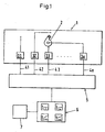
- Ein Blockschema einer Anlage zur Veranschaulichung eines Ausführungsbeispiels des erfindungsgemässen Verfahrens,
- Fig. 2
- ein Flussschema zur Veranschaulichung der Modellierungsphase eines Ausführungsbeispiels des erfindungsgemässen Verfahrens, und
- Fig. 3
- ein Flussschema zur Veranschaulichung eines Ausführungsbeispiels, bei dem eine Aktualisierung des Modells erfolgt.
- Fig. 1:
- A block diagram of a plant for illustrating an embodiment of the method according to the invention,
- Fig. 2
- a flow diagram for illustrating the modeling phase of an embodiment of the inventive method, and
- Fig. 3
- a flow diagram illustrating an embodiment in which an update of the model takes place.
Das erfindungsgemässe Verfahren wird im folgenden mit beispielshaftem Charakter unter Bezugnahme auf ein Wasserkraftwerk mit Turbinen erläutert. Dabei steht das Wasserkraftwerk als repräsentatives Beispiel für eine zu überwachende Anlage und die Turbinen dienen als Beispiel für die hydromechanischen Komponenten der Anlage. Es versteht sich, dass die Erfindung nicht auf solche Fälle beschränkt ist. Die Komponenten können auch andere Strömungsmaschinen wie beispielsweise Pumpen sein oder sonstige mechanische Systeme wie Dampfturbinen, Dampfkessel, Kompressoren, Generatoren, Motoren, Getriebe. Die Anlagen, in denen solche Komponenten integriert sind, können beispielsweise auch Heizanlagen, Lokomotiven, Webmaschinen oder Plasmaspritzanlagen sein.The inventive method will be explained below with exemplary character with reference to a hydroelectric power plant with turbines. The hydroelectric power station is a representative example of a system to be monitored and the turbines serve as an example for the hydromechanical components of the plant. It is understood that the invention is not limited to such cases. The components may also be other turbomachines such as pumps or other mechanical systems such as steam turbines, steam boilers, compressors, generators, motors, transmissions. The systems in which such components are integrated can also be, for example, heating systems, locomotives, weaving machines or plasma spraying systems.
Mit dem Begriff "Zustandsgrössen" sind solche unmittelbar oder mittelbar erfassbaren Grössen gemeint, die der Charakterisierung des Betriebszustands der Komponente bzw. der Anlage dienlich sind oder einen Einfluss auf den Betriebszustand haben. Für das konkrete Beispiel der Turbine bzw. des Wasserkraftwerks umfasst der Begriff Zustandsgrösse beispielsweise die folgenden Grössen: Leistung, Druck vor und hinter der Turbine, Durchflussmenge des Wassers, Temperatur des Wassers, Drehzahl der Turbine, Temperatur des Kühlmediums, Temperatur im Generator, Temperaturen in Wellenlagern oder -dichtungen, Schallemissionen, Vibrationen, Schaufelstellungen usw. Einige der Zustandsgrössen sind vom Bedienpersonal direkt beeinflussbar, wie beispielsweise die Durchflussmenge an Wasser durch die Turbine, andere Zustandsgrössen, wie beispielsweise die Temperatur im Wellenlager oder in der Wellendichtung, sind dagegen nicht direkt beeinflussbar. Es gibt eine Vielzahl von Zustandsgrössen, die jedoch nicht alle unabhängig voneinander sind, sondern in der Regel eine starke Korrelation aufweisen.By the term "state variables" is meant such directly or indirectly detectable quantities that are useful for characterizing the operating state of the component or the system or have an influence on the operating state. For example, for the concrete example of the turbine or hydropower plant, the term state variable includes the following quantities: power, pressure before and after the turbine, flow rate of the water, temperature of the water, speed of the turbine, temperature of the cooling medium, temperature in the generator, temperatures in Shaft bearings or seals, sound emissions, vibrations, blade positions, etc. Some of the state variables are by the operator directly influenced, such as the flow rate of water through the turbine, other state variables, such as the temperature in the shaft bearing or in the shaft seal, however, are not directly influenced. There are a large number of state variables, which however are not all independent of each other, but usually have a strong correlation.
Mit dem "Arbeitspunkt" oder "Betriebspunkt" ist derjenige Betriebszustand gemeint, bei dem die Komponente bzw. die Anlage momentan arbeitet. Jede mit der Komponente oder Anlage realisierbare Kombination von Zustandsgrössen entspricht einem Arbeitspunkt. Die Gesamtheit der möglichen Arbeitspunkte wird als Betriebsbereich bezeichnet. Üblicherweise ist der Arbeitspunkt der Komponente oder der Anlage vom Bedienpersonal vorgebbar, indem direkt beeinflussbare Zustandsgrössen auf den gewünschten Wert eingestellt werden. Läuft die Turbine beispielsweise im Teillastbetrieb, so arbeitet sie an einem anderen Arbeitspunkt als im Volllastbetrieb.By "operating point" or "operating point" is meant that operating state in which the component or the system is currently operating. Each combination of state variables that can be realized with the component or system corresponds to one operating point. The totality of possible operating points is referred to as operating range. Usually, the operating point of the component or the system can be specified by the operating personnel by setting directly influenceable state variables to the desired value. For example, if the turbine is operating in part-load mode, it operates at a different operating point than in full-load operation.
Fig. 1 zeigt eine schematische Blockdarstellung einer Anlage 1 zur Veranschaulichung eines Ausführungsbeispiels des erfindungsgemässen Verfahrens. Die zu überwachende Anlage 1 ist beispielsweise ein Wasserkraftwerk, das als hydromechanische Komponenten Turbinen 2 enthält. Da es für das Verständnis ausreicht, ist in Fig. 1 nur eine der Turbinen 2 symbolisch angedeutet. Natürlich sind üblicherweise mehr als eine Turbine 2 in der Anlage 1 vorgesehen. Ausserdem sind mehrere Sensoren 31,32,33,...,3n zur messtechnischen Erfassung von Zustandsgrössen x1,x2,x3,...,xn vorgesehen. Dabei müssen nicht alle Zustandsgrössen unmittelbar an der Komponente 2 gemessen werden, sondern es können auch Zustandsgrössen an anderen Teilen der Anlage gemessen werden, wie beispielsweis der Druck des Wassers in der Druckleitung. Die Wahl der Zustandsgrössen x1,x2,x3,...,xn, die messtechnisch erfasst werden, richtet sich nach der Art der zu überwachenden Anlage bzw. Komponente. Es obliegt der Erfahrung des Fachmanns, für den jeweiligen Anwendungsfall die geeigneten Zustandsgrössen zu wählen.1 shows a schematic block diagram of a system 1 for illustrating an embodiment of the method according to the invention. The plant 1 to be monitored is, for example, a hydroelectric power plant which contains
Die Sensoren 31-3n übermitteln die von ihnen gemessen Daten über Signalleitungen 41,42,43,..., 4n, beispielsweise fieberoptische Leitungen, an eine Auswerte- und Speichervorrichtung 5, wo die Daten, gegebenenfalls nach einer Aufbereitung oder Weiterverarbeitung, als Messwerte gespeichert werden.The sensors 31-3n transmit the data measured by them via
Die Zustandsgrössen x1,x2,x3,...,xn bilden einen Satz X=(x1,x2,x3,...,xn) von Zustandsgrössen. Während des Betriebs der Turbine 2 werden in vorgebbaren zeitlichen Abständen, beispielsweise jede Minute oder alle 10 Minuten, mittels der Sensoren 31-3n für den festgelegten Satz X von Zustandsgrössen jeweils Messwerte x1t,x2t,x3t,...,xnt erfasst und in der Auswerte- und Speichereinheit gespeichert. Der Messwert x1t bezeichnet den Wert, den die Zustandsgrösse x1 zum Zeitpunkt t hat, oder allgemein: der Messwert xit mit i=1,2,3,...,n bezeichnet den Wert, den die Zustandsgrösse xi zum Zeitpunkt t hat. Dabei ist der Index t gleichbedeutend mit einem Laufindex, der die zeitlich aufeinanderfolgenden Messwerte indiziert.The state variables x 1 , x 2 , x 3 ,..., X n form a set X = (x 1 , x 2 , x 3 ,..., X n ) of state variables. During operation of the
Mittels der Auswerte- und Speichereinheit 5 wird, wie weiter hinten erläutert, ein Modell A (Fig. 2) für das Betriebsverhalten der Komponente 2 erstellt und ausgewertet. Mit Hilfe des Modells A wird in vorgebbaren zeitlichen Abständen mindestens eine Überwachungsgrösse bestimmt, die unabhängig vom jeweils aktuellen Arbeitspunkt ist. Die Überwachungsgrösse, insbesondere ihr zeitlicher Verlauf wird mittels einer Ausgabeeinheit 6 graphisch dargestellt. Anhand des zeitlichen Verlaufs der Überwachungsgrösse lässt sich der Verschleiss beurteilen und es lassen sich Betriebsstörungen detektieren. Mit Verschleiss sind dabei betriebsbedingte, üblicherweise langsam fortschreitende Änderungen gemeint, beispielsweise im Wellenlager oder in der Wellendichtung der Turbine 2 sowie z. B.Ablagerungen in Leitungen oder Verschmutzungen von Filtern. Betriebsstörungen können beispielsweise Ausfälle oder Fehlfunktionen einer der Sensoren 31-3n oder der von ihnen überwachten Aktuatoren (z. B. Ventile, Steuerklappen) sein oder Störungen in der Anlage 1 bzw. der Komponente 2 wie beispielsweise Änderung von Vibrationen oder Überhitzung von Lagern oder Dichtungen.By means of the evaluation and
Ferner ist bei dem in Fig. 1 illustrierten Ausführungsbeispiel eine Warnvorrichtung 7 zum Auslösen eines Alarms vorgesehen. Diese Warnvorrichtung wird aktiviert, falls die Überwachungsgrösse einen vorgebbaren Normalbereich verlässt. Der Alarm kann beispielsweise optisch und/oder akustisch erfolgen.Furthermore, in the embodiment illustrated in FIG. 1, a warning device 7 is provided for triggering an alarm. This warning device is activated if the monitored variable leaves a predefinable normal range. The alarm can be done, for example, visually and / or acoustically.
Im folgenden wird nun anhand des Flussschemas in Fig. 2 die Erstellung des Modells A für das Betriebsverhalten näher erläutert. Das Modell A ist ein Modell, welches direkt aus experimentellen Daten, das heisst aus den mittels der Sensoren 31-3n erfassten Messwerten xit für die Zustandsgrössen xi gewonnen wird. Für die Erstellung des Modells A werden diejenigen Messwerte xit verwendet, die während einer Modellierungsphase erfasst werden. Dabei bezeichnet die Modellierungsphase eine zeitlich begrenzte Betriebsperiode der Komponente 2 bzw. der Anlage 1, während der die Anlage 1 im normalen, das heisst störungsfreien Betrieb arbeitet. Die Wahl der Modellierungsphase kann aufgrund von Erfahrung erfolgen.The preparation of the model A for the operating behavior will now be explained in more detail with reference to the flow chart in FIG. The model A is a model which is obtained directly from experimental data, that is to say from the measured values x it recorded by the sensors 31-3n for the state variables x i . For the creation of the model A, those measured values x it are used, which are acquired during a modeling phase. The modeling phase refers to a time-limited period of operation of the
Beispielsweise wird nach der Inbetriebnahme der Anlage abgewartet, bis typische Einlaufvorgänge abgeschlossen sind. Die Modellierungsphase wird zeitlich so lang gewählt, dass sie mehrere verschiedene Arbeitspunkte aus dem Betriebsbereich der Komponente 2 umfasst. Während der Modellierungsphase werden Messwerte xit für die Zustandsgrössen xi gesammelt. Diese Messwerte xit beziehen sich mithin auf mehrere verschiedenen Arbeitspunkte. Da der zeitliche Abstand der Messwerterfassung, also die Zeit zwischen der Messung t und der Messung t+1 relativ kurz sein kann, ist es gegebenenfalls vorteilhaft, mehrere zeitlich aufeinanderfolgende Messwerte für eine Zustandsgrösse xi zeitlich zu mitteln, oder sonstwie mit bekannten statistischen Methoden zusammenzufassen, beispielsweise durch Bildung von Korrelationsmatrizen. Um dies zu verdeutlichen, wird im folgenden anstelle des Index t der Index T verwendet, um anzudeuten, dass der entsprechende Wert auch die Zusammenfassung von mehreren Einzelwerten darstellen kann. So werden z. B. die Messwerte künftig mit xiT bezeichnet.For example, after commissioning the system, it is necessary to wait until typical run-in processes have been completed. The modeling phase is chosen to be so long that it comprises several different operating points from the operating range of
Aus dem Satz von Zustandsgrössen X wird mindestens eine der Zustandsgrössen xi ausgewählt, für die mittels des Modells A ein Modellwert yi bestimmt wird. Als Eingangsvariablen des Modells A wird zumindest ein Teil des Satzes X der Zustandsgrössen xi verwendet. Der Einfachheit halber wird im folgenden beispielhaft der Fall erläutert, dass genau eine der Zustandsgrössen xi die Ausgangsgrösse des Modells A ist und die übrigen n-1 Zustandsgrössen die Eingangsvariablen des Modells. Es versteht sich jedoch, dass das Modell A in sinngemäss gleicher Weise auch so gestaltet werden kann, dass seine Ausgangsgrössen Modellwerte für mehr als eine der Zustandsgrössen xi umfassen. Prinzipiell ist es egal, welche der Zustandsgrössen xi als Eingangsvariablen gewählt werden und für welche der Zustandsgrössen xi Modellwerte bestimmt werden. Unter praktischen Aspekten ist es jedoch vorteilhaft, wenn die Eingangsvariablen solche Zustandsgrössen xi sind, die direkt vom Bedienpersonal beeinflussbar sind, z. B. der Durchfluss in der Turbinenzuleitung, und die Ausgangsgrössen solche Zustandsgrössen xi, die nicht unmittelbar beeinflussbar sind, z. B. die Temperatur des Wellenlagers oder der Wellendichtung.From the set of state variables X, at least one of the state variables x i is selected for which a model value y i is determined by means of the model A. As input variables of the model A at least a part of the set X of the state variables x i is used. For the sake of simplicity, the following example illustrates the case where exactly one of the state variables x i is the output variable of the model A and the remaining n-1 state variables are the input variables of the model. It is understood, however, that the model A can be configured in a similar manner in such a way that its output variables comprise model values for more than one of the state variables x i . In principle, it does not matter which of the state variables x i are selected as input variables and for which of the state variables x i Model values are determined. From a practical point, however, it is advantageous if the input variables such state variables are x i that can be influenced directly by the operator, for. As the flow in the turbine supply line, and the output variables such state variables x i , which are not directly influenced, z. As the temperature of the shaft bearing or the shaft seal.
Ohne Beschränkung der Allgemeinheit ist in dem hier beschriebenen Ausführungsbeispiel die zu modellierende Zustandsgrösse diejenige mit dem Index n, das heisst die Ausgangsgrösse des Modells ist der Modellwert yn für die Zustandsgrösse xn. Die übrigen Zustandsgrössen xi mit i=1,2,...,n-1 sind die Eingangsvariablen des Modells A.Without limiting the generality, the state variable to be modeled in the exemplary embodiment described here is that with the index n, that is to say the output variable of the model is the model value y n for the state variable x n . The remaining state variables x i with i = 1,2,..., N-1 are the input variables of the model A.
Während der Modellierungsphase werden in der Auswerte-und Speichereinheit 5 insgesamt m Sätze XT (mit T=1,2,...,m) von Messwerten für den Satz von Zustandsgrössen X=(x1,x2,...,xn) abgespeichert, wobei der Index T die zeitlich aufeinanderfolgenden Messwertsätze XT indiziert. Insgesamt liegen also für m Zeiten bzw. Zeitintervalle Messwerte vor. Jeder Satz von Messwerten XT=(x1T,x2T, ... ,xnT) enthält also für jede Zustandsgrösse xi (mit i=1,2,...,n) jeweils den Messwert xiT, den die Zustandsgrösse xi zur Zeit T hatte. Mit X*T (siehe Fig. 2) werden die Messwertsätze XT bezeichnet, die den Messwert xnT für die Zustandsgrösse xn nicht mehr enthalten. Es ist also: X*T=(x1T,x2T,...,x(n-1)T) mit T=1,2,...,m).During the modeling phase, in the evaluation and storage unit 5 a total of m sets X T (with T = 1 , 2 ,..., M) of measured values for the set of state variables X = (x 1 , x 2 ,. x n ), wherein the index T indicates the temporally successive measured value sets X T. Overall, measured values are therefore available for m times or time intervals. Each set of measured values X T = (x 1T , x 2T ,..., X nT ) thus contains the measured value x iT for each state variable x i (with i = 1, 2,..., N) State variable x i at time T had. X * T (see FIG. 2) denotes the measured value sets X T which no longer contain the measured value x nT for the state variable x n . So it is: X * T = (x 1T , x 2T , ..., x (n-1) T ) with T = 1,2, ..., m).
Als Modellstruktur für das Modell A wird im einfachsten Fall eine lineare statische Modellstruktur gewählt, die beispielsweise die folgende Form hat: 
wobei die Grössen ai mit i=0,1,2,...,n-1 Modellparameter sind.As a model structure for the model A, a linear static model structure is chosen in the simplest case, for example, has the following form:
where the quantities a i with i = 0,1,2, ..., n-1 are model parameters.
Die m Sätze XT von Messwerten liefern m Bestimmungsgleichungen für die n Modellparameter ai. Da in der Regel die Anzahl m der Sätze von Messwerten grösser ist als die Anzahl n der Modellparameter ai, ist das System der Bestimmungsgleichungen überbestimmt. Es sind jedoch genügend mathematische Methoden bekannt, um mittels der Bestimmungsgleichungen möglichst gute Werte für die Modellparameter ai zu ermitteln. Beispielsweise geeignet sind Methoden der Ausgleichsrechnung, die Methode der kleinsten Quadrate, die Methode der Singularwertzerlegung (SVD) oder die Principal Component Analysis (PCA). Da solche Methoden hinlänglich bekannt sind, werden sie hier nicht näher erläutert.The m sets X T of measured values provide m determinative equations for the n model parameters a i . Since, as a rule, the number m of the sets of measured values is greater than the number n of the model parameters a i , the system of the determination equations is overdetermined. However, sufficient mathematical methods are known in order to determine the best possible values for the model parameters a i by means of the determination equations. Examples of suitable methods are the Equalization Calculation Method, the least squares method, the Singular Value Decomposition (SVD) method or the Principal Component Analysis (PCA). Since such methods are well known, they will not be explained in detail here.
Mittels des Modells A wird nun für jeden Satz von Messwerten X* T der zugehörige Modellwert ynT gemäss der Beziehung 
bestimmt. Die ynT bilden einen Satz von Modellwerten Y=(yn1,yn2,..ynm), wobei ynT der Modellwert für die Zustandsgrösse xn für die Zeit T ist. Im Schritt 101 (siehe Fig. 2) werden die Modellwerte ynT mit den ihn entsprechenden tatsächlichen Messwerten xnT für die Zustandsgrösse xn verglichen und daraus jeweils ein Residuum rT mit T=1,2,...,m bestimmt, das ein Mass für die Abweichung des Modellwerts ynT vom tatsächlichen Messwert xnT ist. Beispielsweise sind die Residuen rT=xnT-ynT mit T=1,2,...,m die Differenzen aus den tatsächlichem Messwerten xnT und den Modellwerten ynT. Aus der Gesamtheit R=(r1,r2,...,rm) der Residuen wird im Schritt 102 ein Modellfehler ε bestimmt, der ein Mass für die Güte des Modells ist. Der Modellfehler ε kann beispielsweise die normierte Summe der Quadrate der Residuen sein.By means of the model A, the associated model value y nT is calculated according to the relationship for each set of measured values X * T
certainly. The y nT form a set of model values Y = (y n1 , y n2 , .. y nm ), where y nT is the model value for the state variable x n for the time T. In step 101 (see FIG. 2), the model values y nT are compared with the actual measured values x nT corresponding to it for the state variable x n , and one residual r T with t = 1, 2, is a measure of the deviation of the model value y nT from the actual measured value x nT . For example, the residuals r T = x nT -y nT with T = 1, 2,..., M are the differences from the actual measured values x nT and the model values y nT . From the set R = (r 1 , r 2 ,..., R m ) of the residuals, a model error ε is determined in
Im folgenden wird, wie dies die Schritte 102,103 und 105 in Fig. 2 zeigen, durch Bestimmen der Modellparameter ai (Schritt 105) und jeweiliges erneutes Bestimmen des Modellfehlers ε (Schritt 102) das Modell A solange optimiert, bis der Modellfehler ε minimal ist oder eine vorgegebene Grenze unterschreitet. Ist dies erreicht, so ist das Modell A genügend gut für die Überwachung (Schritt 104).In the following, as shown by the
Je nach Art der verwendeten Modellstruktur und/oder der verwendeten Methode zur Bestimmung der Modellparameter ai kann die Erstellung und die Optimierung des Modells A in nur einem Schritt oder aber in mehreren Schritten erfolgen. So ist es beispielsweise möglich, insbesondere bei Modellstrukturen, die linear in den Modellparametern ai sind, die Modellparameter in einem Schritt so zu bestimmen, dass das Modell A bereits optimal ist. Mittels der Methode der kleinsten Quadrate oder der SVD-Methode kann beispielsweise das System der Bestimmungsgleichungen für die Modellparameter ai so gelöst werden, dass die resultiernden Werte für die Modellparameter ai bereits eine optimierte Lösung darstellen. Andererseits ist es auch möglich, dass die Erstellung des Modells A und seine Optimierung in mehreren sukzessiven Schritten erfolgen, also zunächst das Modell A erstellt wird, woraus sich Anfangswerte für die Modellparameter ergeben, und anschliessend in einem oder mehreren iterativen Schritten die Modellparameter solange optimiert werden, bis der Modellfehler minimal ist. Ein solches iteratives Vorgehen ist üblicherweise notwendig, wenn sich die Bestimmungsgleichungen für die Modellparameter nicht analytisch lösen lassen, z. B. wenn als Modellstruktur neuronale Netze verwendet werden.Depending on the type of model structure used and / or the method used to determine the model parameters a i , the creation and optimization of the model A can take place in only one step or in several steps. Thus, for example, it is possible, in particular for model structures which are linear in the model parameters a i , to determine the model parameters in one step such that the model A is already optimal. By means of the method of least squares or the SVD method, for example, the system of the determination equations for the model parameters a i can be solved so that the resulting values for the model parameters a i already represent an optimized solution. On the other hand, it is also possible that the creation of the model A and its optimization in several successive steps, ie the model A is first created, resulting in initial values for the model parameters, and then the model parameters are optimized in one or more iterative steps until the model error is minimal. Such an iterative procedure is usually necessary if the determinative equations for the model parameters do not exist solve analytically, z. For example, if neural networks are used as the model structure.
Nachdem das Modell A anhand der in der Modellierungsphase erfassten Messwerte erstellt und optimiert ist, ist es möglich, für jede derjenigen Kombinationen von Werten der Zustandsgrössen x1,x2,...,xn-1, die einem Arbeitspunkt aus dem Betriebsbereich der Komponente 2 bzw. der Anlage 1 entsprechen, einen Modellwert yn für die Zustandsgrösse xn zu bestimmen, der in sehr guter Näherung angibt, welchen Wert die Zustandsgrösse xn haben müsste, wenn die Komponente 2 bzw. die Anlage 1 im normalen also störungsfreien Betrieb arbeitet. Mit anderen Worten: Das Modell A berücksichtigt den momentanen Arbeitspunkt.After modeling and optimizing the model A based on the measured values acquired in the modeling phase, it is possible, for each of those combinations of values of the quantities x 1 , x 2 , ..., x n-1 , to be an operating point from the operating range of the
Zur Überwachung der Anlage wird beispielsweise wie folgt vorgegangen. In vorgebbaren zeitlichen Abständen, beispielsweise alle paar Minuten, wird von den Sensoren 31-3n ein Messwertsatz für die Zustandsgrössen xi mit i=1,2,...,n erfasst und an die Auswerte- und Speichereinheit 6 übermittelt. Hier wird entweder jeder Messwertsatz einzeln ausgewertet oder die Messwertsätze werden jeweils über eine Zeitdauer, z. B. einen Tag, gesammelt und dann gemittelt oder anders zusammengefasst. Beispielsweise können auch Korrelationen oder Kreuzkorrelationen bestimmt werden. Aus den Messwerten für die Zustandsgrössen x1,x2,...,xn-1 wird dann mittels des Modells A der Modellwert yn bestimmt. Dieser wird von dem zugehörigen tatsächlichen Messwert für die Zustandsgrösse xn subtrahiert und das sich daraus ergebende Residuum r, also die Differenz aus dem jeweils aktuellen Messwert und dem ihm entsprechenden Modellwert yn, wird als Überwachungsgrösse bestimmt. Weil das Modell A den jeweils aktuellen Arbeitspunkt berücksichtigt, ist die Überwachungsgrösse, nämlich das Residuum r, unabhängig vom jeweils aktuellen Arbeitspunkt.To monitor the system, for example, proceed as follows. At predetermined time intervals, for example every few minutes, a measured value set for the state variables x i with i = 1, 2,..., N is detected by the sensors 31 - 3n and transmitted to the evaluation and
Die Überwachungsgrösse wird an die Ausgabeeinheit 6 übermittelt, wo der zeitliche Verlauf der Überwachungsgrösse vorzugsweise graphisch, z. B. auf einem Monitor, dargestellt wird.The monitored variable is transmitted to the
Solange die Komponente 2 bzw. die Anlage 1 im normalen, also störungsfreien, Betrieb arbeitet und kein Verschleiss auftritt, so ist die Überwachungsgrösse, unabhängig vom jeweils aktuellen Arbeitspunkt, zeitlich im wesentlichen konstant. Tritt eine Betriebsstörung auf, beispielsweise ein Ausfall eines Sensors oder eine Überhitzung, so hat dies zur Folge, dass der Modellwert, der ja den normalen Betrieb beschreibt, stärker vom tatsächlichen Messwert abweicht. Folglich ändert sich die Überwachungsgrösse, was in ihrer graphischen Darstellung sehr einfach erkennbar ist. Üblicherweise führt das Auftreten von Betriebsstörungen zu einer zeitlich rasch verlaufenden Änderung der Überwachungsgrösse.As long as the
Treten in der Anlage 1 bzw. der Komponente 2 langsam fortschreitende Veränderungen auf, wie sie beispielsweise durch Verschleiss verursacht werden, so macht sich dies durch eine vergleichsweise langsamere und kontinuierliche Änderung im zeitlichen Verlauf der Überwachungsgrösse bemerkbar.If slowly progressive changes occur in Appendix 1 or
Auch ist es möglich, für die Überwachungsgrösse Schwellenwerte vorzugeben, die den Normalbereich der Überwachungsgrösse begrenzen. Bei Überschreitung der Schwellenwerte wird durch Aktivierung der Warnvorrichtung 7 ein Alarm, z. B. ein optisches und/oder akustisches Signal, ausgelöst oder eine Warnung gegeben. Da die Überwachungsgrösse unabhängig vom jeweils aktuellen Arbeitspunkt ist, sind solche Schwellenwerte für die Überwachungsgrösse gleichbedeutend mit flexiblen, an den jeweiligen Arbeitspunkt angepassten Schwellenwerten für die Zustandsgrössen.It is also possible to specify threshold values for the monitoring variable which limit the normal range of the monitored variable. If the threshold values are exceeded, activation of the warning device 7 causes an alarm, z. As an optical and / or acoustic signal, triggered or given a warning. Since the monitored variable is independent of the current operating point, such threshold values for the monitored variable are synonymous with flexible ones respective operating point adapted thresholds for the state variables.
Vorzugsweise wird der Schwellenwert für die Überwachungsgrösse anhand der Schwankungen der für die Modellierungsphase bestimmten Residuen R=(r1,r2,...,rm) festgelegt, weil diese Schwankungen ein typisches Mass dafür repräsentieren, wie stark die Abweichung zwischen dem Modellwert und dem ihm entsprechenden Messwert im normalen Betrieb sind. Beispielsweise kann der Schwellenwert für die Überwachungsgrösse gleich oder etwas grösser als das grösste der Residuen r1,r2,...rm der Modellierungsphase gewählt werden.Preferably, the threshold for the monitor size is determined from the variations in the residuals R = (r 1 , r 2 , ..., r m ) determined for the modeling phase, because these variations represent a typical measure of how strong the deviation between the model value and the corresponding measured value in normal operation. For example, the threshold value for the monitoring variable can be chosen to be equal to or slightly larger than the largest of the residuals r 1 , r 2 ,... R m of the modeling phase.
Die Modellstruktur für das Modell A kann selbstverständlich auch eine andere als die beschriebene lineare statische sein. Beispielsweise kann die Modellstruktur eine nichtlineare sein, bei der z. B. Produkte der Zustandsgrössen eingehen. Auch ist es möglich eine lineare dynamische Modellstruktur z. B. der folgenden Form zu verwenden: 
Bei dieser dynamischen Modellstruktur werden alle Zustandsgrössen xi als Eingangsvariablen verwendet, wobei in die Bestimmung des Modellwerts für die Zustandsgrösse xnT der Wert dieser Zustandsgrösse zu einem früheren Zeitpunkt,xnT-1, eingeht. Aus praktischen Gründen wird vorzugsweise eine Modellstruktur verwendet, die linear in den Modellparametern ai ist, denn dann sind die Modellparameter ai normalerweise analytisch bestimmbar.In this dynamic model structure, all state variables x i are used as input variables, the value of this state variable being taken into account in the determination of the model value for the state variable x nT at an earlier point in time, x nT-1 . For practical reasons, preferably a model structure is used which is linear in the model parameters a i , because then the model parameters a i can normally be determined analytically.
Es ist aber auch möglich, neuronale Netze als Modellstruktur zu verwenden.But it is also possible to use neural networks as a model structure.
Im folgenden wird anhand des Flussschemas in Fig. 3 noch ein Ausführungsbeispiel des erfindungsgemässen Verfahrens erläutert, bei dem eine Aktualisierung des Modells erfolgt. Auch hier wird der Einfachheit halber mit beispielhaftem Charakter auf den Fall Bezug genommen, dass nur für eine der Zustandsgrössen xi, nämlich die Zustandsgrösse xn, Modellwerte berechnet werden. Es versteht sich jedoch, dass auch bei diesem Ausführungsbeispiel in sinngemäss gleicher Weise mehrere Zustandsgrössen xi modelliert werden können.In the following, an embodiment of the inventive method will be explained with reference to the flowchart in Fig. 3, in which an update of the model takes place. Again, for the sake of simplicity, reference is made to the case with exemplary character that model values are calculated only for one of the state variables x i , namely the state variable x n . However, it is understood that a plurality of state variables x i can also be modeled in a similar manner in this exemplary embodiment.
Um Verwechslungen mit der Modellierungsphase zu vermeiden, wird im folgenden der Index "u" verwendet, um die zeitliche Folge der bestimmten oder erfassten Grössen (Messwerte, Modellwerte, Modelle, Residuen) zu kennzeichnen. So bezeichnet z. B. xiu den Messwert, der zu einer bestimmten, durch "u" bezeichneten Zeit für die Zustandsgrösse xi erfasst wird und xiu+1 den Messwert der für die gleiche Zustandsgrösse xi bei der nächsten Messung erfasst wird. Wie bereits vorne erwähnt, können die Messwerte, die beispielsweise alle paar Minuten erfasst werden, zunächst über eine vorgebbare zeitliche Periode, z. B. einen Tag, gesammelt und dann gemittelt und/oder anders, z. B. durch Bildung von Kreuzkorrelationen zusammengefasst werden, bevor die weiteren Verfahrensschritte erfolgen. Für solche Fälle bezeichnet xiu den über diese durch u bezeichnete Periode gemittelten oder zusammengefassten Messwert. Das heisst, es wird im folgenden nicht unterschieden, ob jeder erfasste Messwertsatz einzeln ausgewertet wird, oder ob eine zeitliche Mittelung über mehrere Messwertsätze erfolgt. Dieser Unterschied ist für das Verständnis unwesentlich.In order to avoid confusion with the modeling phase, the index "u" is used in the following to mark the chronological order of the determined or recorded quantities (measured values, model values, models, residuals). So z. B. x iu the measured value, which is detected at a certain, designated by "u" time for the state variable x i and x iu + 1 the measured value of the same state variable x i is detected in the next measurement. As already mentioned above, the measured values, which are recorded, for example, every few minutes, can first be measured over a predefinable time period, eg. As a day, collected and then averaged and / or different, z. B. are summarized by formation of cross-correlations before the further process steps take place. For such cases, x iu denotes the measurement averaged or summarized over this period denoted by u. This means that it is not differentiated in the following whether each recorded measured value set is evaluated individually, or whether a temporal averaging over several sets of measured values takes place. This difference is immaterial to understanding.
Bei dem in Fig. 3 illustrierten Ausführungsbeispiel wird, analog wie vorne erklärt, zunächst das Modell A anhand der in der Modellierungsphase erfassten Messwerte erstellt und optimiert. Die folgenden Erläuterungen beziehen sich deshalb nur auf den Betrieb der Anlage 1 nach der Modellierungsphase. Auch hier wird in vorgebbaren zeitlichen Abständen jeweils ein Satz von Messwerten x1u,x2u,...,xnu für den Satz von Zustandsgrössen x1,x2,...,xn erfasst (Schritt 201).In the exemplary embodiment illustrated in FIG. 3, analogously, as explained above, the model A is first of all based on created and optimized the measured values acquired in the modeling phase. The following explanations therefore only refer to the operation of Appendix 1 after the modeling phase. Here, too, a set of measured values x 1u , x 2u ,..., X nu for the set of state variables x 1 , x 2 ,..., X n is detected at predeterminable time intervals (step 201).
Während des Betriebs der Anlage 1 wird das Modell A in vorgebbaren zeitlichen Abständen mittels der Auswerte-und Speichervorrichtung 5 aktualisiert, das heisst es wird, wie weiter hinten noch erläutert, jeweils ein aktuelles Modell Mu bestimmt (Schritt 205). Mittels des jeweils aktuellen Modells Mu wird für mindestens einen fixierten Referenzarbeitspunkt jeweils ein Nominalwert snu für die Zustandsgrösse xn bestimmt (Schritt 206), der als Überwachungsgrösse dient und an die Ausgabeeinheit 6 übermittelt wird (Schritt 207). Das heisst, im Unterschied zu dem weiter vorne beschriebenen Ausführungsbeispiel wird zur Bestimmung der Überwachungsgrösse das jeweils aktuelle Modell Mu immer an dem gleichen Referenzarbeitspunkt ausgewertet, unabhängig davon, an welchem Arbeitspunkt die Anlage 1 bzw. die Komponente 2 momentan arbeitet. Dieser fixierte Referenzarbeitspunkt, der durch feste Werte für die Zustandsgrössen xi definiert ist, wird vorzugsweise so gewählt, dass er etwa mitten im Betriebsbereich der Anlage.1 bzw. der Komponente 2 liegt,z. B. am Bestpunkt, oder in der Nähe eines Arbeitspunkts, an dem die Anlage 1 bzw. die Komponente 2 häufig arbeitet bzw. betrieben wird.During operation of the system 1, the model A is updated at predeterminable time intervals by means of the evaluation and
Die Bestimmung und Optimierung des jeweils aktuellen Modells Mu kann beispielsweise in sinngemäss gleicher Weise erfolgen, wie dies vorne anhand der Erstellung des Modells A aus den Messwerten xiT der Modellierungsphase beschrieben ist (siehe Fig. 1). Das heisst die Aktualisierung ist eine neue Bestimmung des Modells anhand des Satzes von Messwerten x1u,x2u,...xnu. Mittels der Messwerte x1u, x2u,...,x(n-1)u wird mit Hilfe des letzten aktuellen Modells Mu-1 oder mit Hilfe des neu bestimmten Modells der Modellwert ynu für die Zustandsgrösse xn bestimmt. Dann wird das Residuum rnu=xnu-ynu gebildet, das die Differenz aus dem tatsächlichen Messwert xnu und dem Modellwert ynu ist. Im folgenden wird dieses Residuum rnu minimiert, bzw. falls mehrere Residuen bestimmt werden, wird ein aus den Residuen bestimmbarer Modellfehler, z. B. die normierte Summe der Quadrate der Residuen, minimiert. Auch hier kann, wie vorne beschrieben, die Erstellung und Optimierung des aktuellen Modells Mu gegebenenfalls in einem Schritt erfolgen. Bevor das letzte aktuelle Modell Nu-1 verändert wird bzw. das Modell neu berechnet wird, werden die zugehörigen Modellparameter des Modells Mu-1 sowie eine Kenngrösse, welche repräsentativ für die Güte dieses Modells Mu-1 ist, beispielsweise Korrelationsmatrizen und/oder geschätzte Varianzen des Messrauschens gespeichert.The determination and optimization of the respective current model M u can, for example, be carried out in a manner similar to that described above with reference to the generation of the model A from the measured values x iT of the modeling phase is described (see Fig. 1). That is, the update is a new determination of the model based on the set of measurements x 1u , x 2u , ... x nu . By means of the measured values x 1u , x 2u , ..., x (n-1) u , the model value y nu for the state variable x n is determined with the aid of the last current model M u-1 or with the help of the newly determined model. Then, the residual r nu = x nu -y nu is formed, which is the difference between the actual measured value x nu and the model value y nu . In the following, this residual r nu is minimized or, if several residuals are determined, a model error that can be determined from the residuals, eg. For example, the normalized sum of the squares of the residuals is minimized. Again, as described above , the creation and optimization of the current model M u may be done in one step. Before the last current model N is changed u-1 and the model is re-calculated, the associated model parameters of the model M u-1, and a characteristic quantity which is representative of the quality of this model M u-1, for example, correlation matrices and / or estimated variances of measurement noise.
Vorzugsweise werden bei der Aktualisierung zur Bestimmung des aktuellen Modells Mu die älteren Modelle, deren Modellparameter und Modellunsicherheiten bzw. Güten gespeichert sind, insbesondere in gewichteter Weise, berücksichtigt. Eine bevorzugte Realisierung dieses Einbeziehens älterer Modelle wird im folgenden anhand des Flussschemas in Fig. 3 erläutert.Preferably, in the update for determining the current model M u, the older models whose model parameters and model uncertainties or qualities are stored, in particular in a weighted manner, are taken into account. A preferred realization of this incorporation of older models is explained below with reference to the flow chart in FIG. 3.
Nachdem im Schritt 201 die Messwerte x1u,x2u,...,xnu bestimmt wurden und gegebenenfalls durch Mittelung und/oder Bildung von Kreuzkorrelationen zusammengefasst sind (Schritt 202), wird im Schritt 203 ein Modell Mu* erstellt und optimiert (z. B. analog wie vorne beschrieben), welches Modell Mu* nur auf denjenigen Messwerten x1u,x2u,...,xnu basiert, die seit der letzten Aktualisierung erfasst wurden. Das Symbol "*" soll also anzeigen, dass zur Erstellung dieses Modells Mu* nur die Messwerte x1u,x2u,...,xnu verwendet werden, die in der durch u indizierten Zeitspanne bestimmt wurden. Analog bezeichnet Mu-1* das Modell, zu dessen Erstellung die in der durch (u-1) indizierten Zeitspanne erfassten Messwerte x1(u-1),x2(u-1),...,xn(u-1) verwendet werden, usw.After the measured values x 1u , x 2u ,..., X nu have been determined in
Im Schritt 204 wird das Modell Mu* zusammen mit Kenngrössen, welche repräsentativ für seinme Güte sind, beispielsweise Korrelationsmatrizen und/oder geschätzte Varianzen des Messrauschens, in der Auswerte- und Speichervorrichtung 5 (Fig. 1) gespeichert.In
Im Schritt 205 wird dann das aktuelle Modell Mu bestimmt, welches die älteren Modelle Mu-1*, Mu-2*, ... berücksichtigt, bestimmt, beispielsweise als Summe der Form:. ![]()
wobei λ einen Gewichtsfaktor bzw. einen Vergessensfaktor bezeichnet. Der Gewichts- oder Vergessensfaktor λ kann beispielsweise aus den Kenngrössen, die jeweils zusammen mit den Modellen Mu-1*, Mu-2*,... gespeichert sind, bestimmt werden. Ein Vorteil dieser Bestimmung des aktuellen Modells Mu ist darin zu sehen, dass die Erinnerungstiefe des aktuellen Modells, also der Einfluss der Historie auf das jeweils aktuelle Modell Mu, über den Faktor λ beeinflussbar und variierbar ist. So kann beispielsweise auch im Nachhinein noch das zu jedem Zeitpunkt jeweils aktuelle Modell Mu, Mu-1, Mu-2,...variiert werden, was eine enorme Flexibilität bedeutet, die insbesondere bei der restrospektiven Analyse der zeitlichen Entwicklung von Betriebsstörungen besonders vorteilhaft ist.In ![]()
where λ denotes a weighting factor or a forgetting factor. The weighting or forgetting factor λ can be determined, for example, from the parameters which are stored together with the models M u-1 *, M u-2 *,... An advantage of this determination of the current model M u can be seen in the fact that the memory depth of the current model, ie the influence of the history on the respectively current model M u , can be influenced and varied by the factor λ. Thus, for example, even at a later date in each case current model M u , M u-1 , M u-2 , ... can be varied, which means an enormous flexibility, especially in the retrospective Analysis of the temporal evolution of breakdowns is particularly advantageous.
Nachdem das aktuelle Modell Mu bestimmt und optimiert ist, wird es an dem Referenzarbeitspunkt ausgewertet (Schritt 206) und somit der Nominalwert snu als Überwachungsgrösse bestimmt und an die Ausgabeeinheit 6(Fig.1) übermittelt.After the current model M u has been determined and optimized, it is evaluated at the reference working point (step 206) and thus the nominal value s nu is determined as the monitoring variable and transmitted to the output unit 6 (FIG. 1).
Alternativ ist es auch möglich, das jeweils aktuelle Modell Mu in der folgenden Form zu bestimmen: 
Auch bei dieser Form berücksichtigt das jeweils aktuelle Modell Mu die älteren Modelle - also die Historie -, denn in die Bestimmung des Modells Mu-1 gingen dann die Modelle Nu-1* und Mu-2 ein, wobei in Mu-2 die Modelle Mu-2* und Mu-3 eingingen, usw. Diese Variante hat den Vorteil besonders wenig Speicherplatz zu benötigen, weil die gesamte Historie (zeitliche Entwicklung) immer nur durch ein Modell beschrieben wird.Even in this form, the respective current model M takes into account and the older models - that is, the history - because in the determination of the model M u-1 walked the models N U 1 * and M U-2, where u in M -2 models M u-2 * and M u-3 , etc. This variant has the advantage of requiring very little storage space, because the entire history (temporal evolution) is always described by a single model.
Es versteht sich, dass zur Berücksichtigung der Historie auch andere Varianten als das hier beschriebene exponentielle Vergessen geeignet sind.Die Aktualisierung zur Bestimmung des jeweils aktuellen Modells Mu erfolgt regelmässig in vorgebbaren zeitlichen Abständen, beispielsweise einmal am Tag. Natürlich ist es auch möglich die Aktualisierung quasi-kontinuierlich durchzuführen, das heisst nach jeder einzelnen Bestimmung des Satzes von Messwerten für die Zustandsgrössen xi.It goes without saying that other variants than the exponential forgetting described here are also suitable for considering the history. The updating for determining the respective current model M u takes place regularly at predefinable time intervals, for example once a day. Of course, it is also possible to carry out the updating quasi-continuously, that is, after each individual determination of the set of measured values for the state variables x i .
Bei diesem Ausführungsbeispiel ist die Überwachungsgrösse nicht eine Differenz aus Messwert und Modellwert, sondern der Nominalwert snu. Dieser ist der Modellwert, der sich für den fixierten Refernzarbeitspunkt aus dem jeweils aktuellen Modell Mu ergibt. Folglich ist auch bei dieser Verfahrensführung die Überwachungsgrösse snu unabhängig vom momentanen Arbeitspunkt. Sie bezieht sich stets auf den fixierten Referenzarbeitspunkt. Anders ausgedrückt gibt die Überwachungsgrösse snu an, welchen Wert die Zustandsgrösse xn haben würde, wenn die Anlage 1 bzw. die Komponente 2 an dem Referenzarbeitspunkt arbeiten würde. Es ist offensichtlich, dass die Überwachungsgrösse snu zeitlich im wesentlichen konstant ist, solange die Anlage 1 bzw. die Komponente 2 im normalen Betrieb arbeitet.In this embodiment, the monitoring quantity is not a difference between measured value and model value, but the nominal value s nu . This is the model value that is for the fixed reference working point from the respective current model M u . Consequently, even with this procedure, the monitoring variable s nu is independent of the current operating point. It always refers to the fixed reference working point. In other words, the monitoring quantity s nu indicates what value the state variable x n would have if the system 1 or the
Die Aktualisierung des Modells erfolgt unabhängig davon, ob eine Betriebsstörung aufgetreten ist oder nicht. Tritt eine Änderung (Störung, Sensorausfall, Verschleiss) in der zu überwachenden Anlage 1. bzw. Komponente 2 auf, so wird diese Änderung bei der Aktualisierung in das aktuelle Modell Mu eingearbeitet. Folglich repräsentiert das aktuelle Modell Mu dann auch nicht mehr den normalen Betrieb, sondern den durch Störung und/oder Verschleiss geänderten Betrieb. Wird das aktueulle Modell nun an dem Refernzarbeitspunkt ausgewertet, so ergibt sich ein Nominalwert snu, der von dem des normalen Betriebs abweicht. Mithin zeigt sich in der graphischen Darstellung der Überwachungsgrösse als Funktion der Zeit eine Abweichung von dem konstanten Verhalten. Auch hier haben Betriebsstörungen in der Regel eine zeitlich relativ rasch verlaufenden Änderung der Überwachungsgrösse zur Folge, während langsam fortschreitende Änderungen, wie sie beispielsweise durch Verschleiss verursacht werden, eine vergleichsweise langsamere und kontinuierliche Änderung im zeitlichen Verlauf der Überwachungsgrösse snu bewirken.The model is updated regardless of whether a malfunction has occurred or not. If a change (fault, sensor failure, wear) occurs in the system 1 or
Ein besonderer Vorteil dieser Art der Überwachung, die auf einen fixierten Referenzarbeitspunkt bezogen ist, liegt darin, dass es auch möglich ist, Trends für den weiteren Betrieb der Komponenten 2 bzw. der Anlage 1 zu erkennen bzw. zu bestimmen. Dies wird am Beispiel des Verschleissens einer Dichtung erläutert. Wenn die Dichtung kontinuierlich verschleisst, so führt dies beispielsweise zu einem kontinuierlichen Anwachsen im zeitlichen Verlauf der Überwachungsgrösse. Da sich die Überwachungsgrösse stets auf denselben Referenzarbeitspunkt bezieht, lässt sich somit voraussagen, wielange die Dichtung noch funktionstüchtig ist. Dadurch lassen sich Wartungsarbeiten wesentlich besser und effizienter planen und es kommt deutlich seltener zu überraschenden unwirtschaftlichen Betriebsausfällen. Auch deshalb lassen sich durch das erfindungsgemässe Verfahren die Instandhaltungs- und Betriebskosten von Anlagen für industrielle Anwendungen erheblich senken.A particular advantage of this kind of monitoring, which is related to a fixed reference work point, lies in the fact that it is also possible to identify or determine trends for the further operation of the
Natürlich können für den fixierten Referenzarbeitspunkt jeweils mehrere Nominalwerte für unterschiedliche Zustandsgrössen bestimmt werden. Auch ist es möglich, mehrere Referenzarbeitspunkte zu fixieren, an denen jeweils das aktuelle Modell Mu ausgewertet wird.Of course, several nominal values for different state variables can be determined in each case for the fixed reference working point. It is also possible to fix several reference work points at which the current model M u is evaluated.
Bei einer bevorzugten Weiterbildung des erfindungsgemässen Verfahrens wird ausser der Detektion von Abweichungen vom normalen Betriebsverhalten auch eine Fehlerisolierung durchgeführt, das heisst der aufgetretenen Fehler wird möglichst gut lokalisiert. Ziel dieser Fehlerisolierung ist es, diejenige Zustandsgrösse bzw. denjenigen Sensor 31-3n möglichst genau zu lokalisieren, der dafür verantwortlich ist, dass die Abweichung vom normalen Betriebsverhalten aufgetreten ist. Dient beispielsweise eine Lagertemperatur als Überwachungsgrösse, so kann eine Abnormalität z. B. einerseits durch eine Fehlfunktion des zugehörigen Sensors verursacht werden, andererseits aber auch durch eine Betriebsstörung in einem anderen Bereich der Komponente bzw. der Anlage, z. B. durch eine unzulässige Erhöhung der Durchflussmenge oder durch eine Fehlfunktion des Sensors, der die Durchflussmenge erfasst.In a preferred development of the method according to the invention, apart from the detection of deviations from the normal operating behavior, an error isolation is also carried out, that is to say the error which has occurred is localized as well as possible. The aim of this fault isolation is to locate as precisely as possible that state variable or sensor 31-3n, which is responsible for ensuring that the deviation from normal operating behavior has occurred. If, for example, a storage temperature serves as the monitoring variable, then an abnormality z. B. on the one hand by a malfunction of the associated Sensors are caused on the other hand, but also by a malfunction in another area of the component or the system, eg. For example, by an inadmissible increase in the flow rate or by a malfunction of the sensor that detects the flow rate.
Die Fehlerisolierung wird vorzugsweise wie folgt durchgeführt:The fault isolation is preferably carried out as follows:
Anhand der erfassten Messwerte für die Zustandsgrössen und/oder eines Gesamtmodells werden mehrere Teilmodelle erstellt, die jeweils eine kleinere Modelldimension als n-1 aufweisen, wobei n die Anzahl der erfassten Zustandsgrössen xi ist. Mittels der Teilmodelle werden rekonstruierte Werte für zumindest einen Teil der Zustandsgrössen ermittelt und durch jeweiliges Vergleichen der rekonstruierten Werte mit den ihnen entsprechenden Messwerten für die Zustandsgrössen wird für jedes Teilmodell ein Rekonstruktionsfehler ermittelt. Durch Vergleichen der Rekonstruktionsfehler mit vorgebbaren Schwellenwerten wird mindestens eine fehlerbehaftete Zustandsgrösse isoliert.On the basis of the measured values for the state parameters and / or of an overall model of a plurality of partial models are created, each having a smaller model dimension than n-1, where x n is the number of the detected state variables i. By means of the submodels, reconstructed values are determined for at least part of the state variables, and by respectively comparing the reconstructed values with the corresponding measured values for the state variables, a reconstruction error is determined for each submodel. By comparing the reconstruction errors with predefinable threshold values, at least one faulty state variable is isolated.
Diese Isolierung soll im folgenden anhand eines sehr einfachen Beispiels verdeutlicht werden. Bei diesem Beispiel werden n=4 Zustandsgrössen x1,x2,x3,x4 messtechnisch erfasst und wie vorne beschrieben das Modell.A für das Betriebsverhalten bzw. das aktuelle Modell Mu bestimmt. Es wird eine lineare Modellstruktur gewählt, beispielsweise ![]()
![]()
Mathematisch ausgedrückt beschreibt diese Gleichung eine dreidimensionale Hyperfläche in einem vierdimensionalen Raum. Da es für das folgende nicht mehr notwendig ist zwischen den Eingangsvariablen und den Ausgangsgrössen des Modells zu unterscheiden kann diese Gleichung auch in der Form ![]()
![]()
Wird nun anhand der Überwachungsgrösse festgestellt, dass eine Betriebsstörung auftritt, so wird diese anhand von Teilmodellen lokalisiert. Ein solches Teilmodell zeichnet sich dadurch aus, dass seine Modelldimension um mindestens eins niedriger ist als die Modelldimension des Modells A bzw des aktuellen Modells Mu. In dem hier erläuterten Beispiel werden zweidimensionale Teilmodelle verwendet, das heisst die Modelldimension der Teilmodelle ist zwei. Es lassen sich die folgenden Teilmodelle bestimmen:
m1(x1,x2,x3); m2(x1,x2,x4); m3(x1,x3,x4); m4(x2,x3,x4)If it is now determined on the basis of the monitoring quantity that a malfunction occurs, this is localized on the basis of partial models. Such a sub-model is characterized by the fact that its model dimension is at least one lower than the model dimension of the model A or the current model M u . In the example explained here, two-dimensional partial models are used, ie the model dimension of the partial models is two. The following submodels can be determined:
m1 (x 1, x 2, x 3); m2 (x 1, x 2, x 4); m3 (x 1, x 3, x 4); m4 (x 2 , x 3 , x 4 )
Das Teilmodell m1 hat beispielsweise die Form: 
wobei b0,b1 und b2 Modellparameter bezeichnen. Die Zustandsgrösse x4 geht in das Teilmodell m1 nicht mehr ein. In analoger Weise geht die Zustandsgrösse x3 in das Teilmodell m2 nicht mehr ein, die Zustandsgrösse x2 geht in das Teilmodell m3 nicht mehr ein, und die Zustandsgrösse x1 geht in das Teilmodell m4 nicht mehr ein.The submodel m1 has the form, for example:
where b 0 , b 1 and b 2 designate model parameters. The state variable x 4 is no longer included in the submodel m1. In an analogous manner, the state variable x 3 no longer enters the submodel m2, the state variable x 2 no longer enters into the submodel m3, and the State variable x 1 is no longer included in submodel m4.
Wie bereits erwähnt, ist es für die Teilmodelle m1-m4 unerheblich, welche der Zustandsgrössen xi als Eingangsvariablen dienen und welche als Ausgangsgrössen. So ist es beispielsweise mit dem Teilmodell m1 möglich, die Zustandsgrösse x1 aus den Zustandsgrössen x2 und x3 zu berechnen, oder die Zustandsgrösse x2 aus den Zustandsgrössen x1 und x3 zu berechnen, oder die Zustandsgrösse x3 aus den Zustandsgrössen x1 und x2 zu berechnen. Analoges gilt für die Teilmodelle m2,m3 und m4.As already mentioned, it is irrelevant for the submodels m1-m4 which of the state variables x i serve as input variables and which as output variables. For example, with the partial model m1 it is possible to calculate the state variable x 1 from the state variables x 2 and x 3 , or to calculate the state variable x 2 from the state variables x 1 and x 3 , or the state variable x 3 from the state variables x 1 and x 2 to calculate. The same applies to the partial models m2, m3 and m4.
Mittels der Teilmodelle m1-m4 werden nun für die Zustandsgrössen x1,x2,x3,x4 Werte bestimmt, die als rekonstruierte Werte bezeichnet werden. Durch jeweiliges Vergleichen der rekonstruierten Werte mit den ihnen entsprechenden Messwerten xiT bzw. xiu für die Zustandsgrössen xi wird für jedes der Teilmodelle m1-m4 ein Rekonstruktionsfehler bestimmt, der repräsentativ dafür ist, wie gut die mittels des zugehörigen Teilmodells bestimmten rekonstruierten Werte mit den Messwerten übereinstimmen. Ist der Rekonstruktionsfehler grösser als ein vorgebbarer Schwellenwert, so wird das zugehörige Teilmodell als fehlerhaft beurteilt, anderenfalls als nicht fehlerhaft. Die Schwellenwerte für die Rekonstruktionsfehler lassen sich beispielsweise anhand der Residuen, die z. B. in der Modellierungsphase bestimmt wurden, festlegen.By means of the submodels m1-m4, values are now determined for the state variables x 1 , x 2 , x 3 , x 4 , which are referred to as reconstructed values. By respectively comparing the reconstructed values with their corresponding measured values x iT and x iu for the state variables x i , a reconstruction error is determined for each of the submodels m 1-m 4, which is representative of how well the reconstructed values determined by the associated submodel match match the measured values. If the reconstruction error is greater than a predefinable threshold value, the associated submodel is assessed as faulty, otherwise it is not faulty. The thresholds for the reconstruction errors can be, for example, based on the residuals, the z. As determined in the modeling phase set.
Somit werden die Teilmodelle in zwei Klassen eingeteilt: in fehlerhafte und in nicht fehlerhafte. Anhand der Kombinationen von Zustandsgrössen xi die zu fehlerhaften Teilmodellen führen, und der Kombinationen von Zustandsgrössen xi, die zu nicht fehlerhaften Teilmodellen führen, lässt sich dann die fehlerbehaftete Zustandsgrösse isolieren.Thus, the submodels are divided into two classes: erroneous and non-defective. Based on the combinations of state variables x i that lead to defective submodels, and the combinations of state variables x i that are not faulty Submodels lead, then can isolate the faulty state variable.
Dies sei am erwähnten einfachen Beispiel mit vier Zustandsgrössen erläutert. Ist z. B. die Zustandsgrösse x1 fehlerbehaftet, weil beispielsweise der Sensor 31 nicht korrekt arbeitet, so führt dies im allgemeinen dazu, dass alle die Teilmodelle, in denen x1 vorkommt, also die Teilmodelle m1,m2 und m3, als fehlerhaft beurteilt werden, weil ihr Rekonstruktionsfehler zu gross ist. Dagegen wird das Teilmodell m4 den kleinsten Rekonstruktionsfehler aufweisen und als nicht fehlerbehaftet beurteilt, weil die Zustandsgrösse x1 in dieses Teilmodell m4 nicht eingeht.This is explained in the above-mentioned simple example with four state variables. Is z. If, for example, the state variable x 1 is faulty because, for example, the
Analog führt eine Fehlerbehaftung der Zustandsgrösse x2 bzw. des Sensors 32 dazu, dass nur das Teilmodell, in welches x2 nicht eingeht, nämlich m3, als nicht fehlerhaft beurteilt wird.Analogously, a fault liability of the state variable x 2 or of the
Eine Fehlerbehaftung der Zustandsgrösse x3 bzw. des Sensors 33 führt dazu, dass nur das Teilmodell m2 als nicht fehlerbehaftet beurteilt wird, und eine Fehlerbehaftung der Zustandsgrösse x4 bzw. des Sensors 34 führt dazu, dass nur das Teilmodell m1 nicht fehlerhaft ist.An error of the state variable x 3 or the
Auf diese Weise lässt sich anhand der Teilmodelle m1-m4 der Fehler lokalisieren, genauer gesagt, die fehlerhafte Zustandsgrösse bzw. der fehlerhafte Sensor kann isoliert werden.In this way, the error can be localized on the basis of the partial models m1-m4, more precisely, the faulty state variable or the faulty sensor can be isolated.
Das hier beschriebenen Vorgehen zur Fehlerisolierung lässt sich in einfacher Weise auf allgemein n Zustandsgrössen xi mit i=1,2,...,n ausdehnen. Bei n Zustandsgrössen xi ist die maximale Modelldimension des Modells für das Betriebsverhalten n-1, das heisst das Modell für das Betriebsverhalten bestimmt in dem n-dimensionalen Raum der n Zustandsgrössen eine n-1-dimensionale Hyperfläche. Die für die Fehlerisolierung benötigten Teilmodelle haben jeweils eine Modelldimension d, die kleiner ist als die Modelldimension n-1 des Modells für das Betriebsverhalten, das heisst d < n-1. Folglich repräsentiert jedes Teilmodell eine d-dimensionale Hyperfläche in einen (d+1)-dimensionalen Raum. Da die n Zustandsgrössen xi im allgemeinen stark korreliert, also nicht unabhängig voneinander sind, ist das Modell A bzw. Mu für das Betriebsverhalten analytisch redundant. Aufgrund dieser analytischen Redundanz lassen sich durch die Teilmodelle die Fehler isolieren.The procedure for error isolation described here can be extended in a simple manner to generally n state variables x i with i = 1, 2,..., N. For n state variables x i , the maximum model dimension of the Model for the operating behavior n-1, that is, the model for the operating behavior determines an n-1-dimensional hypersurface in the n-dimensional space of the n state variables. The partial models required for fault isolation each have a model dimension d that is smaller than the model dimension n-1 of the model for the operating behavior, that is d <n-1. Thus, each sub-model represents a d-dimensional hypersurface into a (d + 1) -dimensional space. Since the n state variables x i are generally highly correlated, ie not independent of one another, the model A or M u is analytically redundant for the operating behavior. Due to this analytical redundancy, the errors can be isolated by the submodels.
Die Anzahl der fehlerhaften Zustandsgrössen bzw. der fehlerhaft arbeitenden Sensoren, die sich mittels der Teilmodelle isolieren lassen, ist gleich der Differenz aus der Modelldimension des Modells für das Betriebsverhalten und der Modelldimension der einzelnen Teilmodelle. Für praktische Anwendungeen ist es häufig ausreichend, wenn diese Differenz eins beträgt.The number of faulty state variables or faulty sensors that can be isolated by means of the submodels equals the difference between the model dimension of the model for the operating behavior and the model dimension of the individual submodels. For practical purposes, it is often sufficient if this difference is one.
Es versteht sich, dass für die Teilmodelle auch anderer Modellstrukturen als die hier beispielhaft erwähnte lineare Modellstruktur verwendet werden können. Die vornestehenden Erläuterungen bezüglich der Modellstruktur des Modells für das Betriebsverhalten gelten sinngemäss auch für die Teilmodelle.It goes without saying that it is also possible to use model structures other than the linear model structure mentioned here by way of example for the submodels. The above explanations regarding the model structure of the model for the operating behavior apply mutatis mutandis to the submodels.
Die Erstellung der einzelnen Teilmodelle kann beispielsweise in sinngemäss gleicher Weise erfolgen wie die Erstellung des Modells für das Betriebsverhalten, also direkt aus den Messwerten für die Zustandsgrössen. Alternativ ist aber auch das folgende Vorgehen möglich. Zunächst wird, beispielsweise mittels der SVD-Methode, ein Gesamtmodell erstellt, dessen Modelldimension gleich der Modelldimension d der zu bestimmenden Teilmodelle ist, wobei jedoch alle Zustandsgrössen xi mit i=1,2,...,n in dieses Gesamtmodell eingehen. Dieses Gesamtmodell ist folglich analytisch redundant. Anschliessend werden durch jeweiliges Eliminieren mindestens einer der Zustandsgrössen xi aus dem Gesamtmodell die einzelnen Teilmodelle bestimmt, das heisst, das Gesamtmodell wird jeweils auf einen Raum niedrigerer Dimension projiziert. Die hierfür benötigten mathematischen Methoden zur Projektion sind an sich bekannt und werden hier nicht näher erläutert.The creation of the individual submodels can, for example, be done in the same way as the creation of the model for the operating behavior, ie directly from the measured values for the state variables. Alternatively, however, the following procedure is possible. First, for example, using the SVD method, creates an overall model whose model dimension is equal to the model dimension d of the submodels to be determined, although all state variables x i with i = 1, 2,..., n enter into this overall model. This overall model is therefore analytically redundant. Then, by respectively eliminating at least one of the state variables x i from the overall model, the individual submodels are determined, that is, the overall model is projected onto a space of a lower dimension in each case. The mathematical methods required for projection are known per se and will not be explained in detail here.
Die Bestimmung einer geeigneten Modelldimension d für die Teilmodelle bzw. für das Gesamtmodell kann beispielsweise mittels der SVD-Methode erfolgen.The determination of a suitable model dimension d for the submodels or for the overall model can be done, for example, by means of the SVD method.
Die Bestimmung, Speicherung und Auswertung der Teilmodelle erfolgt vorzugsweise in der Auswerte- und Speichervorrichtung 5.The determination, storage and evaluation of the partial models preferably takes place in the evaluation and
Claims (11)
- A method for monitoring plants with mechanical, in particular hydromechanical, components which can be operated at variable working points, including the following steps:a) during the operation of the components (2) measured values (xiT; xiu) are determined in each case at predeterminable time intervals for a fixed set of state parameters (xi),b) the measured values (xiT), which are determined for various working points during a modelling phase which is carried out beforehand and in which the plant works in problem-free operation, are used for the generation of a model (A) for the operating behaviour of the components (2), whereini) the input variables of the model (A) are at least some of the set of the state parameters (xi) and the output values include a model value (ynT) for at least one of the state parameters (xn),ii) a residue (rT) is determined in each case by comparison of the respective model value (ynT) with the corresponding actual measured value (xnT) of the modelling phase,iii) the model (A) is optimised by determination of model parameters in such a manner that a modelling error (ε) which is derivable from the residues (rT) is a minimum,c) with the help of the model (A) for the operating behaviour at least one monitored parameter (r; snu) is derived at predeterminable time intervals which is independent of the respective current working point,d) the temporal behaviour of the monitored parameter (r; snu) is used for estimating the wear in the components (2) and/or for the detection of operating disturbances.
- A method in accordance with claim 1, wherein the determined measured values (xiT; xiu) are stored in an evaluation and storage apparatus (5), with the generation and evaluation of the model (A) taking place in the evaluation and storage apparatus (5), and wherein a warning apparatus (7) is activated for the triggering of an alarm in the event that the monitored parameter (r; snu) departs from a predeterminable normal range.
- A method in accordance with any one of the preceding claims, with the monitored parameter (r) being the difference between the respective current measured value (xn) and the model value (yn) corresponding to it.
- A method in accordance with any one of the preceding claims, wherein an updating takes place at predeterminable time intervals by means of the evaluation and storage apparatus (5) for the determination of a current model (Mu) in which the measured values (xiu) which were determined since the last updating of the model are taken into consideration.
- A method in accordance with claim 4, wherein certain models (Mu, Mu-1, Mu-2) determined at different times are stored in the evaluation and storage apparatus (5) in each case together with characteristic parameters which are representative of the quality of the respective model.
- A method in accordance with claim 5, wherein the older models (Mu, Mu-1*, Mu-2*) are taken into consideration, in particular in a weighted manner, in the updating for the determination of the current model (Mu).
- A method in accordance with any one of the claims 4 to 6, wherein the respective current model (Mu) is optimised by means of the evaluation and storage apparatus (5) in thata) for each of the measured values (xiu) which were determined since the last updating of the model, a respective residue is calculated for the associated state parameter (xi) by comparison with the model values corresponding to them,b) the model parameters are determined in such a manner that the modelling error which can be determined from the residues is a minimum.
- A method in accordance with any one of the claims 4 to 7, whereina) at least one reference working point is fixed,b) after each updating of the model, the associated model value is determined for the fixed reference working point by means of the respective current model (Mu) of the associated model value as a nominal value (snu) for the corresponding state parameter (xn) by the evaluation and storage apparatus (5),c) the temporal behaviour of the nominal value (snu) is used for the estimation of the wear in the components (2) and/or for the detection of disturbances in the operation.
- A method in accordance with claim 8, wherein a plurality of nominal values for different state parameters (xi) is determined for the fixed reference working point in each case.
- A method in accordance with any one of the preceding claims, wherein a fault isolation is carried out in the event of a deviation from normal operating behaviour in thata) a plurality of partial models (m1, m2, m3, m4) are generated on the basis of the measured values determined for the state parameters and/or of an overall model, each of the part models having a model dimension (d) smaller than n-1, with n being the number of the state parameters (xi) determined;b) reconstructed values for at least some of the state parameters (xi) are determined by means of the partial models (m1, m2, m3, m4);c) a reconstruction error is determined by respective comparison of the reconstructed values with measured values for the state parameters (xi) corresponding to them for each partial model (m1, m2, m3, m4);d) at least one faulty state parameter is isolated by comparison of the reconstruction error with predeterminable threshold values.
- A method in accordance with claim 10, wherein the partial models (m1, m2, m3, m4), the reconstruction errors of which are greater than the predeterminable threshold value are rated as faulty; and wherein the faulty state parameter or the faulty state parameters are isolated on the basis of the combinations of state parameters (xi) which lead to faulty partial models and the combinations of state parameters (xi) which lead to non-faulty partial models.
Priority Applications (7)
| Application Number | Priority Date | Filing Date | Title |
|---|---|---|---|
| DE59712546T DE59712546D1 (en) | 1997-07-31 | 1997-07-31 | Method for monitoring systems with mechanical components |
| AT97810550T ATE315815T1 (en) | 1997-07-31 | 1997-07-31 | METHOD FOR MONITORING SYSTEMS WITH MECHANICAL COMPONENTS |
| EP97810550A EP0895197B1 (en) | 1997-07-31 | 1997-07-31 | Method for monitoring installations with mechanical components |
| US09/006,925 US6208953B1 (en) | 1997-07-31 | 1998-01-14 | Method for monitoring plants with mechanical components |
| EG89398A EG22325A (en) | 1997-07-31 | 1998-07-29 | Method for monitoring plants with mechanical components |
| DZ980185A DZ2575A1 (en) | 1997-07-31 | 1998-07-29 | Method for monitoring installations with mechanical components. |
| NO19983514A NO322764B1 (en) | 1997-07-31 | 1998-07-30 | Procedure for monitoring systems with mechanical components |
Applications Claiming Priority (1)
| Application Number | Priority Date | Filing Date | Title |
|---|---|---|---|
| EP97810550A EP0895197B1 (en) | 1997-07-31 | 1997-07-31 | Method for monitoring installations with mechanical components |
Publications (2)
| Publication Number | Publication Date |
|---|---|
| EP0895197A1 EP0895197A1 (en) | 1999-02-03 |
| EP0895197B1 true EP0895197B1 (en) | 2006-01-11 |
Family
ID=8230334
Family Applications (1)
| Application Number | Title | Priority Date | Filing Date |
|---|---|---|---|
| EP97810550A Expired - Lifetime EP0895197B1 (en) | 1997-07-31 | 1997-07-31 | Method for monitoring installations with mechanical components |
Country Status (7)
| Country | Link |
|---|---|
| US (1) | US6208953B1 (en) |
| EP (1) | EP0895197B1 (en) |
| AT (1) | ATE315815T1 (en) |
| DE (1) | DE59712546D1 (en) |
| DZ (1) | DZ2575A1 (en) |
| EG (1) | EG22325A (en) |
| NO (1) | NO322764B1 (en) |
Cited By (1)
| Publication number | Priority date | Publication date | Assignee | Title |
|---|---|---|---|---|
| WO2012055699A1 (en) | 2010-10-28 | 2012-05-03 | Eads Deutschland Gmbh | Maintenance information apparatus, state sensor for use therein, and method which can be performed thereby for making a decision for or against maintenance |
Families Citing this family (53)
| Publication number | Priority date | Publication date | Assignee | Title |
|---|---|---|---|---|
| GB9822992D0 (en) | 1998-10-22 | 1998-12-16 | British Aerospace | Fatigue monitoring systems and methods |
| US6944583B1 (en) * | 2000-02-02 | 2005-09-13 | Centric Software, Inc. | Multi-threaded frame safe synchronization of a simulation |
| US6539343B2 (en) * | 2000-02-03 | 2003-03-25 | Xerox Corporation | Methods for condition monitoring and system-level diagnosis of electro-mechanical systems with multiple actuating components operating in multiple regimes |
| FI20000454A0 (en) * | 2000-02-28 | 2000-02-28 | Neles Paper Automation Oy | Monitoring system and its use |
| DE60105421T2 (en) * | 2000-04-05 | 2005-09-22 | Liqum Oy | METHOD AND SYSTEM FOR MONITORING AND ANALYZING A PAPER MANUFACTURING PROCESS |
| WO2002015131A1 (en) * | 2000-08-17 | 2002-02-21 | Siemens Aktiengesellschaft | Diagnosis method for detecting ageing symptoms in a steam turbine |
| JP3855651B2 (en) * | 2000-08-29 | 2006-12-13 | 日本精工株式会社 | Rolling bearing life prediction method, life prediction device, rolling bearing selection device using the life prediction device, and storage medium |
| EP1189126B1 (en) * | 2000-09-14 | 2006-06-28 | Sulzer Markets and Technology AG | Method for monitoring an installation |
| US6587737B2 (en) | 2000-09-14 | 2003-07-01 | Sulzer Makert And Technology Ag | Method for the monitoring of a plant |
| FI20002296A (en) * | 2000-10-17 | 2002-04-18 | Lumeo Software Oy | Simulation of a system with a mechanical subsystem and a hydraulic subsystem |
| US6477485B1 (en) * | 2000-10-27 | 2002-11-05 | Otis Elevator Company | Monitoring system behavior using empirical distributions and cumulative distribution norms |
| US7299162B2 (en) * | 2000-12-14 | 2007-11-20 | Siemens Corporate Research, Inc. | Method and apparatus for providing a polynomial based virtual age estimation for remaining lifetime prediction of a system |
| US6795798B2 (en) * | 2001-03-01 | 2004-09-21 | Fisher-Rosemount Systems, Inc. | Remote analysis of process control plant data |
| JP4138267B2 (en) * | 2001-03-23 | 2008-08-27 | 株式会社東芝 | Semiconductor manufacturing apparatus, vacuum pump life prediction method, and vacuum pump repair timing determination method |
| US6532433B2 (en) | 2001-04-17 | 2003-03-11 | General Electric Company | Method and apparatus for continuous prediction, monitoring and control of compressor health via detection of precursors to rotating stall and surge |
| GB0109643D0 (en) * | 2001-04-19 | 2001-06-13 | Isis Innovation | System and method for monitoring and control |
| DE10121728A1 (en) | 2001-05-04 | 2002-11-07 | Infineon Technologies Ag | Process for hybrid automated monitoring of production machines |
| CA2450177C (en) * | 2001-06-08 | 2012-09-11 | Netuitive, Inc. | Automated analyzers for estimation systems |
| US20030046382A1 (en) * | 2001-08-21 | 2003-03-06 | Sascha Nick | System and method for scalable multi-level remote diagnosis and predictive maintenance |
| JP4184638B2 (en) * | 2001-08-31 | 2008-11-19 | 株式会社東芝 | Life diagnosis method for semiconductor manufacturing equipment |
| JP2003077907A (en) * | 2001-08-31 | 2003-03-14 | Toshiba Corp | Method and system for avoiding abnormal stop of manufacturing apparatus |
| JP4149691B2 (en) * | 2001-08-31 | 2008-09-10 | 株式会社東芝 | Method for predicting life of rotating machine for semiconductor manufacturing apparatus and semiconductor manufacturing apparatus |
| US20030069743A1 (en) * | 2001-09-21 | 2003-04-10 | Nordrum Susann B. | System and method for energy and green-house gas inventory management |
| US7280988B2 (en) * | 2001-12-19 | 2007-10-09 | Netuitive, Inc. | Method and system for analyzing and predicting the performance of computer network using time series measurements |
| FI114170B (en) * | 2002-03-14 | 2004-08-31 | Metso Automation Oy | Condition monitoring system for machines with rotary machine elements with machine control system |
| US7097351B2 (en) * | 2002-09-30 | 2006-08-29 | Flowserve Management Company | System of monitoring operating conditions of rotating equipment |
| WO2005045678A2 (en) | 2003-10-27 | 2005-05-19 | Netuitive, Inc. | Computer performance estimation system configured to take expected events into consideration |
| US20050096759A1 (en) * | 2003-10-31 | 2005-05-05 | General Electric Company | Distributed power generation plant automated event assessment and mitigation plan determination process |
| DE50306976D1 (en) | 2003-11-19 | 2007-05-16 | Siemens Ag | Method for monitoring a technical device |
| US7062370B2 (en) * | 2004-03-30 | 2006-06-13 | Honeywell International Inc. | Model-based detection, diagnosis of turbine engine faults |
| US7369965B2 (en) * | 2004-06-28 | 2008-05-06 | Honeywell International, Inc. | System and method for turbine engine anomaly detection |
| WO2006007621A2 (en) * | 2004-07-22 | 2006-01-26 | Avl List Gmbh | Method for analyzing the behavior of complex systems, especially internal combustion engines |
| US7457674B2 (en) * | 2004-08-27 | 2008-11-25 | Siemens Corporate Research, Inc. | System, device, and methods for updating system-monitoring models |
| CN101048714B (en) * | 2004-08-27 | 2010-05-12 | 西门子共同研究公司 | System, device, and methods for updating system-monitoring models |
| WO2006107295A1 (en) * | 2005-04-01 | 2006-10-12 | Honeywell International Inc. | Model-based detection, diagnosis of turbine engine faults |
| US7536371B2 (en) * | 2005-12-05 | 2009-05-19 | Insyst Ltd. | Apparatus and method for the analysis of a process having parameter-based faults |
| DE102007019201B4 (en) | 2007-04-20 | 2009-06-04 | Phoenix Contact Gmbh & Co. Kg | Matching data of a control and / or data transmission system and a system model representing this |
| DE102007028891A1 (en) * | 2007-06-20 | 2009-01-15 | Evonik Energy Services Gmbh | Method for monitoring the stress of a pipeline section |
| DE102008016025A1 (en) * | 2008-03-28 | 2009-10-01 | Mtu Aero Engines Gmbh | Method and measuring system for characterizing a deviation of an actual dimension of a component from a nominal dimension of the component |
| US8306778B2 (en) * | 2008-12-23 | 2012-11-06 | Embraer S.A. | Prognostics and health monitoring for electro-mechanical systems and components |
| US8955365B2 (en) * | 2008-12-23 | 2015-02-17 | Embraer S.A. | Performance monitoring and prognostics for aircraft pneumatic control valves |
| EP2287685B1 (en) * | 2009-07-23 | 2015-07-15 | Siemens Aktiengesellschaft | Method for monitoring operation behaviour of a component of an industrial plant |
| DE102011081346A1 (en) * | 2011-08-22 | 2013-02-28 | Robert Bosch Gmbh | Method of creating a function for a controller |
| US9529348B2 (en) | 2012-01-24 | 2016-12-27 | Emerson Process Management Power & Water Solutions, Inc. | Method and apparatus for deploying industrial plant simulators using cloud computing technologies |
| US9957843B2 (en) | 2013-12-31 | 2018-05-01 | General Electric Company | Methods and systems for enhancing control of power plant generating units |
| US20150184549A1 (en) | 2013-12-31 | 2015-07-02 | General Electric Company | Methods and systems for enhancing control of power plant generating units |
| DE102017219543A1 (en) * | 2017-11-03 | 2019-05-09 | Robert Bosch Gmbh | Method and device for monitoring the operation of a plant |
| DE102017131087A1 (en) * | 2017-12-22 | 2019-06-27 | Endress + Hauser Process Solutions Ag | Method for monitoring a measuring point in a process automation system |
| WO2019222152A1 (en) * | 2018-05-18 | 2019-11-21 | Siemens Aktiengesellschaft | Online fault localization in industrial processes without utilizing a dynamic system model |
| JP7267109B2 (en) * | 2019-05-31 | 2023-05-01 | 三菱重工業株式会社 | Steam turbine seal clearance adjustment method |
| DE102021116562A1 (en) | 2021-06-25 | 2022-12-29 | Schenck Process Europe Gmbh | MONITORING THE OPERATION OF A MACHINE |
| DE102021003960A1 (en) | 2021-07-28 | 2023-02-02 | Stöber Antriebstechnik GmbH & Co. KG | Method for detecting impending failures of machine components, in particular drive units |
| DE102021208443A1 (en) | 2021-08-04 | 2023-02-09 | BSH Hausgeräte GmbH | Detection of an anomaly on a household appliance |
Family Cites Families (16)
| Publication number | Priority date | Publication date | Assignee | Title |
|---|---|---|---|---|
| US4184205A (en) * | 1977-11-25 | 1980-01-15 | Ird Mechanalysis, Inc. | Data acquisition system |
| DD146359B3 (en) * | 1979-09-26 | 1992-07-30 | Veag Vereinigte Energiewerke Ag | PROCESS FOR COMPONENT MONITORING AND PROCESS CONTROL IN STEAM GENERATOR PLANTS |
| DE3133222A1 (en) * | 1981-08-21 | 1983-03-03 | Kraftwerk Union AG, 4330 Mülheim | Method for determining the instantaneous state and the future state of a technical process with the aid of nonlinear process models |
| FR2539874B1 (en) * | 1983-01-20 | 1985-07-05 | Alsthom Atlantique | MONITORING SYSTEM FOR TORSIONAL DAMAGE OF A SHAFT LINE COMPOSED OF A DRIVING MACHINE AND A DRIVEN MACHINE |
| US4719587A (en) * | 1985-04-16 | 1988-01-12 | Combustion Engineering, Inc. | Future behavior equipment predictive system |
| SE463338B (en) * | 1989-06-14 | 1990-11-05 | Ludwik Liszka | SETTING TO MONITOR AND / OR DIAGNOSTIC CURRENT OPERATING CONDITIONS WITH COMPLIED MACHINES |
| US5210704A (en) * | 1990-10-02 | 1993-05-11 | Technology International Incorporated | System for prognosis and diagnostics of failure and wearout monitoring and for prediction of life expectancy of helicopter gearboxes and other rotating equipment |
| EP0496570B1 (en) * | 1991-01-22 | 1998-06-03 | Honeywell Inc. | Two-level system identifier apparatus with optimization |
| FR2676556B1 (en) * | 1991-05-15 | 1993-07-23 | Europ Gas Turbines Sa | PREDICTIVE PROCESS MONITORING SYSTEM. |
| FR2677152B1 (en) * | 1991-05-28 | 1993-08-06 | Europ Gas Turbines Sa | METHOD AND DEVICE FOR MONITORING AN APPARATUS OPERATING UNDER VARIABLE CONDITIONS. |
| US5633800A (en) * | 1992-10-21 | 1997-05-27 | General Electric Company | Integrated model-based reasoning/expert system diagnosis for rotating machinery |
| DE4243882C1 (en) * | 1992-12-23 | 1994-01-05 | Baleanu Michael Alin | Method and device for monitoring a technical process |
| US5465321A (en) * | 1993-04-07 | 1995-11-07 | The United States Of America As Represented By The Administrator Of The National Aeronautics And Space Administration | Hidden markov models for fault detection in dynamic systems |
| JP3169036B2 (en) * | 1993-06-04 | 2001-05-21 | 株式会社日立製作所 | Plant monitoring and diagnosis system, plant monitoring and diagnosis method, and nondestructive inspection and diagnosis method |
| JPH07132440A (en) * | 1993-11-02 | 1995-05-23 | Fanuc Ltd | Machining load monitoring system |
| US5796920A (en) * | 1994-08-19 | 1998-08-18 | Harris Corporation | Multiprocessor system and method for identification and adaptive control of dynamic systems |
-
1997
- 1997-07-31 EP EP97810550A patent/EP0895197B1/en not_active Expired - Lifetime
- 1997-07-31 DE DE59712546T patent/DE59712546D1/en not_active Expired - Lifetime
- 1997-07-31 AT AT97810550T patent/ATE315815T1/en not_active IP Right Cessation
-
1998
- 1998-01-14 US US09/006,925 patent/US6208953B1/en not_active Expired - Fee Related
- 1998-07-29 EG EG89398A patent/EG22325A/en active
- 1998-07-29 DZ DZ980185A patent/DZ2575A1/en active
- 1998-07-30 NO NO19983514A patent/NO322764B1/en not_active IP Right Cessation
Cited By (3)
| Publication number | Priority date | Publication date | Assignee | Title |
|---|---|---|---|---|
| WO2012055699A1 (en) | 2010-10-28 | 2012-05-03 | Eads Deutschland Gmbh | Maintenance information apparatus, state sensor for use therein, and method which can be performed thereby for making a decision for or against maintenance |
| DE102010049909A1 (en) | 2010-10-28 | 2012-05-03 | Eads Deutschland Gmbh | Maintenance information device, condition sensor for use therein, and method of decision making for or against maintenance that can be performed thereby |
| US9477222B2 (en) | 2010-10-28 | 2016-10-25 | Eads Deutschland Gmbh | Maintenance information device, condition sensor for use therein and method which can be carried out therewith for arriving at a decision whether or not to perform servicing or maintenance |
Also Published As
| Publication number | Publication date |
|---|---|
| EG22325A (en) | 2002-12-31 |
| DZ2575A1 (en) | 2003-02-22 |
| EP0895197A1 (en) | 1999-02-03 |
| NO322764B1 (en) | 2006-12-04 |
| DE59712546D1 (en) | 2006-04-06 |
| US6208953B1 (en) | 2001-03-27 |
| ATE315815T1 (en) | 2006-02-15 |
| NO983514L (en) | 1999-02-01 |
| NO983514D0 (en) | 1998-07-30 |
Similar Documents
| Publication | Publication Date | Title |
|---|---|---|
| EP0895197B1 (en) | Method for monitoring installations with mechanical components | |
| EP1543394B1 (en) | Method and device for monitoring a technical installation comprising several systems, in particular an electric power station | |
| DE69910800T2 (en) | Method and device for monitoring the operating state of a single machine | |
| DE3421522A1 (en) | METHOD AND DEVICE FOR DIAGNOSIS OF A THERMAL POWER PLANT | |
| DE2622120A1 (en) | PROCEDURE AND DEVICE FOR AUTOMATIC MONITORING OF SYSTEMS | |
| EP2706422B1 (en) | Method for computer-implemented monitoring of the operation of a technical system, in particular an electrical energy production assembly | |
| EP1892597A1 (en) | State monitoring for machines and technical equipment | |
| DE112018001684T5 (en) | Indicator detection system and indicator detection method | |
| EP3282399B1 (en) | Method for the improved detection of process anomalies of a technical installation and corresponding diagnostic system | |
| EP3876060B1 (en) | Method and computing unit for analyzing the reason for an anomalous state of a machine | |
| WO2020216530A1 (en) | Method for determining remaining useful life cycles, remaining useful life cycle determination circuit, and remaining useful life cycle determination apparatus | |
| DE102008037532A1 (en) | Automatic detection and reporting of wear of internal turbine components | |
| DE102020202865B3 (en) | Method and computing unit for monitoring the condition of a machine | |
| EP1189126B1 (en) | Method for monitoring an installation | |
| DE69728942T2 (en) | System for evaluating the state of a vacuum pump | |
| DE102019101910B4 (en) | Thermal offset correction device | |
| DE102020200051A1 (en) | Method for determining remaining usage cycles, remaining usage cycle determining circuit, remaining usage cycle determining device | |
| DE102017205712B4 (en) | Computer-implemented method for operating a shaft grounding system, shaft grounding system of a rotary apparatus | |
| EP2388602B1 (en) | Method for diagnosing contacts of a photovoltaic assembly and device | |
| EP2206024B1 (en) | Method for monitoring the quality of a control system in a power plant | |
| EP1055162A1 (en) | Process and installation diagnostic method | |
| EP3819727B1 (en) | Control system for a technical installation with a trend curve diagram | |
| EP4226494A1 (en) | Method for monitoring one or more electric drives of an electromechanical system | |
| EP3959571A1 (en) | Method for determining remaining useful life cycles, remaining useful life cycle determination circuit, and remaining useful life cycle determination apparatus | |
| EP4127848A1 (en) | Method and system for diagnosing messages |
Legal Events
| Date | Code | Title | Description |
|---|---|---|---|
| PUAI | Public reference made under article 153(3) epc to a published international application that has entered the european phase |
Free format text: ORIGINAL CODE: 0009012 |
|
| AK | Designated contracting states |
Kind code of ref document: A1 Designated state(s): AT CH DE FR GB IT LI NL |
|
| AX | Request for extension of the european patent |
Free format text: AL;LT;LV;RO;SI |
|
| 17P | Request for examination filed |
Effective date: 19990706 |
|
| AKX | Designation fees paid |
Free format text: AT CH DE FR GB IT LI NL |
|
| 17Q | First examination report despatched |
Effective date: 20021112 |
|
| RAP1 | Party data changed (applicant data changed or rights of an application transferred) |
Owner name: SULZER MARKETS AND TECHNOLOGY AG |
|
| GRAP | Despatch of communication of intention to grant a patent |
Free format text: ORIGINAL CODE: EPIDOSNIGR1 |
|
| GRAS | Grant fee paid |
Free format text: ORIGINAL CODE: EPIDOSNIGR3 |
|
| GRAA | (expected) grant |
Free format text: ORIGINAL CODE: 0009210 |
|
| AK | Designated contracting states |
Kind code of ref document: B1 Designated state(s): AT CH DE FR GB IT LI NL |
|
| REG | Reference to a national code |
Ref country code: CH Ref legal event code: NV Representative=s name: SULZER MANAGEMENT AG PATENTABTEILUNG/0067 Ref country code: CH Ref legal event code: EP |
|
| GBT | Gb: translation of ep patent filed (gb section 77(6)(a)/1977) |
Effective date: 20060111 |
|
| REF | Corresponds to: |
Ref document number: 59712546 Country of ref document: DE Date of ref document: 20060406 Kind code of ref document: P |
|
| ET | Fr: translation filed | ||
| PLBE | No opposition filed within time limit |
Free format text: ORIGINAL CODE: 0009261 |
|
| STAA | Information on the status of an ep patent application or granted ep patent |
Free format text: STATUS: NO OPPOSITION FILED WITHIN TIME LIMIT |
|
| 26N | No opposition filed |
Effective date: 20061012 |
|
| PGFP | Annual fee paid to national office [announced via postgrant information from national office to epo] |
Ref country code: NL Payment date: 20100714 Year of fee payment: 14 Ref country code: CH Payment date: 20100726 Year of fee payment: 14 |
|
| PGFP | Annual fee paid to national office [announced via postgrant information from national office to epo] |
Ref country code: IT Payment date: 20100726 Year of fee payment: 14 Ref country code: FR Payment date: 20100805 Year of fee payment: 14 Ref country code: DE Payment date: 20100723 Year of fee payment: 14 Ref country code: AT Payment date: 20100714 Year of fee payment: 14 |
|
| PGFP | Annual fee paid to national office [announced via postgrant information from national office to epo] |
Ref country code: GB Payment date: 20100722 Year of fee payment: 14 |
|
| REG | Reference to a national code |
Ref country code: NL Ref legal event code: V1 Effective date: 20120201 |
|
| REG | Reference to a national code |
Ref country code: CH Ref legal event code: PL |
|
| GBPC | Gb: european patent ceased through non-payment of renewal fee |
Effective date: 20110731 |
|
| REG | Reference to a national code |
Ref country code: AT Ref legal event code: MM01 Ref document number: 315815 Country of ref document: AT Kind code of ref document: T Effective date: 20110731 |
|
| REG | Reference to a national code |
Ref country code: FR Ref legal event code: ST Effective date: 20120330 |
|
| PG25 | Lapsed in a contracting state [announced via postgrant information from national office to epo] |
Ref country code: CH Free format text: LAPSE BECAUSE OF NON-PAYMENT OF DUE FEES Effective date: 20110731 Ref country code: FR Free format text: LAPSE BECAUSE OF NON-PAYMENT OF DUE FEES Effective date: 20110801 Ref country code: LI Free format text: LAPSE BECAUSE OF NON-PAYMENT OF DUE FEES Effective date: 20110731 Ref country code: DE Free format text: LAPSE BECAUSE OF NON-PAYMENT OF DUE FEES Effective date: 20120201 |
|
| REG | Reference to a national code |
Ref country code: DE Ref legal event code: R119 Ref document number: 59712546 Country of ref document: DE Effective date: 20120201 |
|
| PG25 | Lapsed in a contracting state [announced via postgrant information from national office to epo] |
Ref country code: IT Free format text: LAPSE BECAUSE OF NON-PAYMENT OF DUE FEES Effective date: 20110731 Ref country code: NL Free format text: LAPSE BECAUSE OF NON-PAYMENT OF DUE FEES Effective date: 20120201 |
|
| PG25 | Lapsed in a contracting state [announced via postgrant information from national office to epo] |
Ref country code: GB Free format text: LAPSE BECAUSE OF NON-PAYMENT OF DUE FEES Effective date: 20110731 |
|
| PG25 | Lapsed in a contracting state [announced via postgrant information from national office to epo] |
Ref country code: AT Free format text: LAPSE BECAUSE OF NON-PAYMENT OF DUE FEES Effective date: 20110731 |