EP0895387A1 - Detection of the transmission mode of a DVB signal - Google Patents
Detection of the transmission mode of a DVB signal Download PDFInfo
- Publication number
- EP0895387A1 EP0895387A1 EP97112929A EP97112929A EP0895387A1 EP 0895387 A1 EP0895387 A1 EP 0895387A1 EP 97112929 A EP97112929 A EP 97112929A EP 97112929 A EP97112929 A EP 97112929A EP 0895387 A1 EP0895387 A1 EP 0895387A1
- Authority
- EP
- European Patent Office
- Prior art keywords
- correlation
- afc
- fft
- rough
- synchronization
- Prior art date
- Legal status (The legal status is an assumption and is not a legal conclusion. Google has not performed a legal analysis and makes no representation as to the accuracy of the status listed.)
- Withdrawn
Links
Images
Classifications
-
- H—ELECTRICITY
- H04—ELECTRIC COMMUNICATION TECHNIQUE
- H04N—PICTORIAL COMMUNICATION, e.g. TELEVISION
- H04N21/00—Selective content distribution, e.g. interactive television or video on demand [VOD]
- H04N21/40—Client devices specifically adapted for the reception of or interaction with content, e.g. set-top-box [STB]; Operations thereof
- H04N21/43—Processing of content or additional data, e.g. demultiplexing additional data from a digital video stream; Elementary client operations, e.g. monitoring of home network or synchronising decoder's clock; Client middleware
- H04N21/438—Interfacing the downstream path of the transmission network originating from a server, e.g. retrieving MPEG packets from an IP network
- H04N21/4382—Demodulation or channel decoding, e.g. QPSK demodulation
-
- H—ELECTRICITY
- H04—ELECTRIC COMMUNICATION TECHNIQUE
- H04L—TRANSMISSION OF DIGITAL INFORMATION, e.g. TELEGRAPHIC COMMUNICATION
- H04L27/00—Modulated-carrier systems
- H04L27/26—Systems using multi-frequency codes
- H04L27/2601—Multicarrier modulation systems
- H04L27/2647—Arrangements specific to the receiver only
- H04L27/2655—Synchronisation arrangements
- H04L27/2657—Carrier synchronisation
-
- H—ELECTRICITY
- H04—ELECTRIC COMMUNICATION TECHNIQUE
- H04L—TRANSMISSION OF DIGITAL INFORMATION, e.g. TELEGRAPHIC COMMUNICATION
- H04L27/00—Modulated-carrier systems
- H04L27/26—Systems using multi-frequency codes
- H04L27/2601—Multicarrier modulation systems
- H04L27/2647—Arrangements specific to the receiver only
- H04L27/2655—Synchronisation arrangements
- H04L27/2662—Symbol synchronisation
- H04L27/2665—Fine synchronisation, e.g. by positioning the FFT window
-
- H—ELECTRICITY
- H04—ELECTRIC COMMUNICATION TECHNIQUE
- H04N—PICTORIAL COMMUNICATION, e.g. TELEVISION
- H04N21/00—Selective content distribution, e.g. interactive television or video on demand [VOD]
- H04N21/20—Servers specifically adapted for the distribution of content, e.g. VOD servers; Operations thereof
- H04N21/23—Processing of content or additional data; Elementary server operations; Server middleware
- H04N21/238—Interfacing the downstream path of the transmission network, e.g. adapting the transmission rate of a video stream to network bandwidth; Processing of multiplex streams
- H04N21/2383—Channel coding or modulation of digital bit-stream, e.g. QPSK modulation
-
- H—ELECTRICITY
- H04—ELECTRIC COMMUNICATION TECHNIQUE
- H04H—BROADCAST COMMUNICATION
- H04H20/00—Arrangements for broadcast or for distribution combined with broadcast
- H04H20/65—Arrangements characterised by transmission systems for broadcast
- H04H20/71—Wireless systems
- H04H20/72—Wireless systems of terrestrial networks
Definitions
- the invention relates to a method and a receiver for the reception of multicarrier digital signals.
- Modulation types such as OFDM, QPSK and QAM can be used for the terrestrial transmission of digital television and radio signals (hereinafter generally referred to as radio signals).
- broadcast signals are DVB (digital video broadcast), HDTV-T (hierarchical digital television transmission) and DAB (digital audio broadcast).
- the basic principles of the DVB system are specified in ETS 300 744.
- the data of the digital radio signals are arranged in two-dimensional (time and frequency, hereinafter referred to as 'temporal spectral') frames or frames, which have a time length of T F and in the case of ETS 300 744 consist of 68 OFDM symbols. Four frames form a super frame.
- 'temporal spectral' time and frequency
- the symbols of duration T s are formed from 1705 carriers (2K mode) or from 6817 carriers (8K mode) with different frequencies.
- the 2K mode is particularly suitable for single transmitters and small SFN networks (single frequency network) with limited transmitter spacing.
- the 8K mode can be used for individual transmitters and for small and large SFN networks.
- the symbols have a time length of T s with a useful part of length T u and a guard interval of length ⁇ .
- the guard interval is formed by a cyclical continuation of the useful part and is arranged in time before it. All symbols contain data and reference information. Each symbol can be viewed as a group of cells, with one cell corresponding to each carrier.
- the frames contain scattered pilots, continuous pilot signals and TPS carriers or pilots (transmission parameter signaling). These are, for example, in ETS 300 744, March 1997, in chapters 4.4. to 4.6.
- the pilot cells or carriers contain reference information, the transmitted value of which is known to the recipient.
- the continuous pilot signals can coincide with every fourth symbol with a scattered pilot cell.
- the value or content of the scattered and continuous pilot signals is derived, for example, from a pseudo-random binary sequence w k for each of the transmitted carriers k.
- the sequence w k can also determine the start phase of the TPS carrier information.
- the pilot cells or carriers can be used on the receiver side for frame synchronization, frequency synchronization, time synchronization, channel estimation and transmission mode identification. Whether and how these options are used by the recipient is up to the recipient manufacturer. A corresponding system for use with DAB is described in EP-A-0 786 889.
- the invention has for its object an improved Method of tuning when receiving multicarrier digital signals or to check system conformity to specify such received digital signals. This task is solved by the method specified in claim 1.
- the invention is based on the further object of a receiver to indicate the application of the method according to the invention. This object is achieved by the specified in claim 13 Receiver solved.
- a rough time synchronization is first combined with a mode detection and possibly additionally a rough AFC (automatic frequency correction) both when searching for and identifying received signals and during their constant monitoring.
- the time signal is correlated with the time signal shifted by a useful symbol length T u .
- This correlation can be carried out several times, for example five times per data frame.
- signal samples with different lengths T u are used in accordance with the respective mode, and the resultant correlation result maxima is then used to infer the current mode (for example 2K or 8K mode). If there is no usable correlation result maximum, the correlation steps can be repeated.
- the guard interval used is determined from the distance and / or the amplitude of the maxima, taking into account the mode, and a scanning window is subsequently positioned. This can be done by setting a counter that is synchronous with the symbol sequence (T u + ⁇ ) and that outputs a time window with duration T u . This time window is also referred to below as the sampling window or FFT window. A base oscillator used and thus the position of the window are readjusted in later steps via a fine-time synchronization.
- the Invention in general a Fourier transform or another transformation that is a frequency spectral Allows display from the time domain to the frequency domain, are used. From the signal thus converted become pilot cells according to the intended arrangement scheme taken and with the values provided according to the specification correlated. According to the specification, e.g. in 2K mode 45 Positions and with 8K mode 177 positions of the spectrum continuous pilot signals. Become a correlation e.g. in 2K mode ⁇ 16 such sets (over ⁇ 16 carrier spacing) and in 8K mode ⁇ 64 such sets (over ⁇ 64 carrier spacing) used.
- the Frequency shift of the baseband signal can be determined. This The result is used to roughly correct the frequency, e.g. by means of a multiplier M arranged in front of the FFT part used so that the frequency deviation in further steps is less than ⁇ 1/2 beam spacing.
- next frequency evaluation can take place after a larger distance, e.g. can be used for the purpose of synchronization control A total of 3 to 6 such evaluations were carried out per frame to the computational effort in a reasonable order of magnitude to keep.
- the intermediate value or more precise value of the deviation determined in this way is already taken into account in the frequency correction described above.
- the coarse frequency setting with better accuracy than ⁇ 1/2 carrier spacing (-F s / 2 ⁇ f ⁇ F s / 2) is the prerequisite for the subsequent takeover of the AFG function by the so-called fine control.
- the achieved accuracy can be determined after a rough adjustment by checking the frequency again. In this case, the result should be -F s / 3 ⁇ f ⁇ F s / 3rd be.
- a ratio is (in each case) formed from the determined value of the maximum (or center value in the case of the time correlation) and the average value that does not correspond to the maximum or to the center area associated other partial correlation results.
- a range of length T u can be selected from the results of the time correlation, the maximum not necessarily having to be in the middle.
- An area with a length of ⁇ 1/2 guard interval length should be left out in the average value calculation.
- the center of the center area can be determined, for example, by determining the points at -6dB and calculating a central position.
- the entire range of ⁇ 16 individual steps (in 2K mode) or ⁇ 64 individual steps (in 8K mode) is used, for example, to evaluate the correlation partial results determined over frequency.
- the main maximum can lie outside the center and there can be secondary maxima with a greater distance. Secondary lines may also exist in the area of ⁇ F s around the main maximum, but these are to be counted as the main maximum and due to a deviation of the signal position from the grid F s in the size of -F s / 2 ⁇ ⁇ f ⁇ F s / 2nd arise.
- the average value C av is calculated, for example, as the root mean square of all partial correlation results that do not belong to the main maximum or central area: the range l 1 +1 to l 2 -1 relates to the recessed part.
- the sum of the squares of the real and imaginary parts can also be formed instead of the amount. From a practical point of view, further simplifications are possible, for example, when changing the formula and changing the minimum values accordingly, instead of dividing and calculating the square root, multiplications can be carried out, ie squaring the maximum values and multiplying by the divisor used in the formula. Under favorable signal conditions and lower demands on the quality of the statement, it may be sufficient to calculate only the simple mean.
- a reception signal is generated during the Looking for or trying to receive a certain signal or during ongoing reception as "system-compliant” or “available” or “not system-compliant” or “not available” featured.
- the tests carried out result in a high degree of certainty, or the probability of a false statement is extremely low. This means that the next steps can be targeted. If the result is negative (ie no system conformity), it is no longer necessary, for example, to initiate decoding of the signal in order to check the conformity again. This can save a lot of time in signal search processes and thus avoid unnecessary waiting times for the user of the receiver.
- the further decoding of the signal is either initiated during the search process or during a reception test or the search process is continued or the information “not available” is output during the reception test.
- Fine AFC can now be continued respectively. For this, e.g. ongoing the phase changes of the continuous pilot signals between two successive ones Symbols determined individually, the results averaged, a frequency deviation from the end result determined in this way calculated and with this a frequency correction of the signal before the FFT. Symbolically one after the other determined final results or frequency deviations can advantageously be summarized over several symbols and be filtered.
- a frame synchronization and a time-fine synchronization can then be carried out or sampling clock adjustment. This happens e.g. through a temporal evaluation (pulse response) of the 'scattered pilots' and corresponding readjustment of the sampling clock reference oscillator, where (again) expediently a plurality of values which follow one another in time be summarized and filtered.
- a control or warning signal is output to the other parts of the receiver, so that under certain Conditions - eg failure of some symbols - appropriate measures can be initiated, such as "freezing" the last acceptable picture and / or muting the audio channel.
- An advantage of the invention is that security is significantly increased in signal identification and identification at the earliest possible point within the Signal decoding at the receiving end and thus also at the earliest possible stage Time occurs so that no unnecessary playback interruptions must be initiated. On the other hand but there is an absolutely necessary interruption fast. Unacceptable faults such as of the Failure or incorrect decoding of some or even all pixel blocks of an image or loud or abrupt Noise in the sound can be largely avoided.
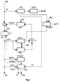
- a rough synchronization is first carried out for the digital input signal INP in coarse time synchronization means CTS.
- the time signal is correlated with the time signal shifted by a useful symbol length T u , for example twice to five times per data frame.
- samples with different lengths T u are used in accordance with the respective mode, and on the basis of the resulting, filtered or averaged correlation result maxima, MDET is then used in mode detector means to determine the currently available mode MO (for example 2K or 8K). Mode) closed, eg by comparing the maxima with a stored threshold. MDET outputs a corresponding mode information MO. If there is no usable correlation result maximum, the correlation steps can be repeated in CTS.
- the guard interval used is determined in CTS from the distance between the correlation maxima, taking into account the mode, and a scanning window is subsequently positioned, for example by once setting a counter in CTS that is synchronous with the symbol sequence (T u + ⁇ ), which outputs a time window with duration T u , for example by means of a start signal ST, which is fed to time-fine synchronization means FTS.
- the position of the sampling window FFTWIN and the sampling clock are readjusted in FTS by means of a base oscillator VCX0 used here.
- the input signal INP consisting of an I and Q component is multiplied in a multiplier M by a frequency correction signal FCORR originating from an oscillator NCO.
- the M output signal selected with FFTWIN is converted into the frequency domain in Fast Fourier transform means FFT and ultimately forms the output signal OU consisting of an I and Q component.
- FFT Fast Fourier transform
- OU consisting of an I and Q component.
- a rough AFC can be carried out by rough AFC means CAFC.
- the intended continuous pilot signals CPIL of the current symbol of a data frame are taken from the output signal of FFT and correlated in CAFC with a fixed scheme (45 positions in 2K mode, 177 positions in 8K mode), namely over ⁇ 16 shifts in 2K Mode or ⁇ 64 shifts in 8K mode.
- the type of correlation is chosen according to MO.
- QREV also receives the MO mode information.
- the QREV output signal RC then controls corresponding parts of the receiver. After positioning the scanning window and / or reaching ⁇ f ⁇ D max , the above-mentioned conditions are checked at certain time intervals for the purpose of checking the synchronization. If, for example, the result is 2 to 10 times negative, the system is restarted with the rough time synchronization in CTS.
- the received signal is identified in the receiver as "system-compliant” or “available” or “non-system-compliant” or “not available”.
- the further decoding of the signal is initiated during the search process or during a reception test or the search process is continued or the information “not available” is output during the reception test.
- a fine AFC can now be carried out.
- the phase change of the continuous pilot signals CPIL from symbol to symbol is determined and averaged over all pilot signals CPIL (45 in 2K mode, 177 in 8K mode).
- a frame synchronization and a Fine time synchronization or sampling clock adjustment This is done by evaluating the output signal from FFT TPS pilot cells taken from TPSPIL, in a TPS decoder TPSDEC can be decoded. Its output signal is also the time-fine synchronization means FTS supplied and causes a corresponding readjustment of the basic oscillator VCX0 for obtaining the sampling clock CL and a Correction of the position of the FFTWIN scanning window.
- the beginning of the frame (FTS output signal FTSO) and the position of the 'scattered pilots' is generated using the sync sequence of the TPS pilot cells determined by correlation.
- the sampling clock CL is supplied to all circuit parts shown in Fig. 1.
- the 'scattered pilots' can be interpolated in time in FTS so that every third carrier can be regarded as a 'scattered pilot'.
- the impulse response is determined on the basis of the 'scattered pilots' interpolated over time with the aid of a division by the specified 'scattered pilots' setpoints and an inverse FFT. Then the deviation of the center of the impulse response from a desired position desired for optimal reception is determined. This process is advantageously repeated 3 to 7 times per frame. The result is advantageously filtered in blocks and then further used.
- the sampling clock reference oscillator VCX0 is adjusted in FTS from the size and direction of the deviation determined in this way. This readjustment can also be carried out by means of the oscillator NCO and multiplier M.
- NCO can contain a digital PLL.
- the invention can be used in DVB receivers or in receivers for comparable digital signals are used, e.g. also in DAB receivers.
- the specified numerical values are then changed accordingly and the individual synchronization or Review steps will be updated to those in the frame transferred reference or synchronization data adapted.
- the DAB receiver will then replace the one described here Coarse AFC correlation method (basis is continuous Pilot signals) that described in EP-A-0 786 889 Procedure (based on CAZAC symbols).
- the qualitative Evaluation of the correlation results achieved is essentially identical.
- the evaluations according to the invention are particularly advantageous in combined receivers (DAB and DVB-T or digital and analog).
Abstract
Description
Die Erfindung betrifft ein Verfahren und einen Empfänger für den Empfang von Multicarrier-Digitalsignalen.The invention relates to a method and a receiver for the reception of multicarrier digital signals.
Für die terrestrische Übertragung von digitalen Fernseh- und
Rundfunksignalen (im folgenden allgemein Rundfunksignale genannt)
können Modulation-Typen wie OFDM, QPSK und QAM verwendet
werden. Beispiele für solche Rundfunksignale sind DVB
(digital video broadcast), HDTV-T (hierarchical digital television
transmission) und DAB (digital audio broadcast).
Das DVB-System ist in seinen Grundlagen in ETS 300 744 spezifiziert.
Die Daten der digitalen Rundfunksignale sind in zweidimensionalen
(Zeit und Frequenz, im Folgenden als 'temporalspektral'
bezeichnet) Rahmen oder Frames angeordnet, die eine
zeitliche Länge von TF haben und im Fall von ETS 300 744
aus 68 OFDM-Symbolen bestehen. Vier Rahmen bilden einen Super-Rahmen.
Bei den obengenannten Übertragungs-Systemen für
digitale Audio- oder Videosignale sind verschiedene Übertragungs-Modi
möglich. Im Fall von ETS 300 744 werden die Symbole
der Dauer Ts gebildet aus jeweils 1705 Trägern (2K-Mode)
oder aus jeweils 6817 Trägern (8K-Mode) mit unterschiedlichen
Frequenzen.
Der 2K-Mode ist insbesondere für einzelne Sender und kleine
SFN-Netzwerke (single frequency network) mit begrenzten Sender-Abständen
geeignet.
Der 8K-Mode kann für einzelne Sender und für kleine und große
SFN-Netzwerke verwendet werden.
Die Symbole haben eine zeitliche Länge von Ts mit einem
Nutzteil der Länge Tu und einem Guard-Intervall der Länge Δ.
Das Guard-Intervall wird durch eine zyklische Fortsetzung
des Nutzteils gebildet und ist zeitlich vor diesem angeordnet.
Alle Symbole enthalten Daten und Referenz-Information.
Jedes Symbol kann als eine Gruppe von Zellen angesehen werden,
wobei jedem Träger eine Zelle entspricht.
Die Rahmen enthalten außer den eigentlichen Bild-, Ton-,
oder sonstigen Daten verstreute Pilotzellen (scattered pilots),
kontinuierliche Pilotsignalen und TPS-Träger oder
-Pilots (transmission parameter signalling) . Diese sind z.B.
in ETS 300 744, März 1997, in den Kapiteln 4.4. bis 4.6 beschrieben.
Die Pilotzellen bzw. -Träger enthalten Referenz-Information,
deren übertragener Wert dem Empfänger bekannt ist. Die kontinuierlichen
Pilotsignalen können beispielsweise bei jedem
vierten Symbol mit einer verstreuten Pilotzelle in Koinzidenz
sein. Der Wert bzw. Inhalt der verstreuten und kontinuierlichen
Pilotsignalen ist z.B. von einer Pseudo-Zufalls-Binärsequenz
wk für jeden der übertragenen Träger k abgeleitet.
Die Sequenz wk kann auch die Startphase der TPS-Trägerinformation
bestimmen. Die Pilotzellen bzw. -Träger können
empfängerseitig zur Rahmen-Synchronisation, Frequenz-Synchronisation,
Zeit-Synchronisation, Kanalschätzung und Übertragungs-Mode-Identifizierung
verwendet werden. Ob und wie
diese Möglichkeiten empfängerseitig genutzt werden, bleibt
dem Empfänger-Hersteller überlassen.
In EP-A-0 786 889 ist ein entsprechendes System für die Ahwendung
bei DAB beschrieben.Modulation types such as OFDM, QPSK and QAM can be used for the terrestrial transmission of digital television and radio signals (hereinafter generally referred to as radio signals). Examples of such broadcast signals are DVB (digital video broadcast), HDTV-T (hierarchical digital television transmission) and DAB (digital audio broadcast). The basic principles of the DVB system are specified in ETS 300 744.
The data of the digital radio signals are arranged in two-dimensional (time and frequency, hereinafter referred to as 'temporal spectral') frames or frames, which have a time length of T F and in the case of ETS 300 744 consist of 68 OFDM symbols. Four frames form a super frame. Various transmission modes are possible in the transmission systems for digital audio or video signals mentioned above. In the case of ETS 300 744, the symbols of duration T s are formed from 1705 carriers (2K mode) or from 6817 carriers (8K mode) with different frequencies.
The 2K mode is particularly suitable for single transmitters and small SFN networks (single frequency network) with limited transmitter spacing.
The 8K mode can be used for individual transmitters and for small and large SFN networks.
The symbols have a time length of T s with a useful part of length T u and a guard interval of length Δ. The guard interval is formed by a cyclical continuation of the useful part and is arranged in time before it. All symbols contain data and reference information. Each symbol can be viewed as a group of cells, with one cell corresponding to each carrier.
In addition to the actual image, sound or other data, the frames contain scattered pilots, continuous pilot signals and TPS carriers or pilots (transmission parameter signaling). These are, for example, in ETS 300 744, March 1997, in chapters 4.4. to 4.6.
The pilot cells or carriers contain reference information, the transmitted value of which is known to the recipient. For example, the continuous pilot signals can coincide with every fourth symbol with a scattered pilot cell. The value or content of the scattered and continuous pilot signals is derived, for example, from a pseudo-random binary sequence w k for each of the transmitted carriers k. The sequence w k can also determine the start phase of the TPS carrier information. The pilot cells or carriers can be used on the receiver side for frame synchronization, frequency synchronization, time synchronization, channel estimation and transmission mode identification. Whether and how these options are used by the recipient is up to the recipient manufacturer.
A corresponding system for use with DAB is described in EP-A-0 786 889.
Ein wichtige Überlegung im Zusammenhang mit solchen Systemen ist es, ein systemkonformes Signal in dem Fall zu finden, wo ein Empfänger eingeschaltet oder auf einen anderen Kanal abgestimmt wird. Dazu muß der Empfänger verschiedenen Dienste voneinander unterscheiden können, z.B. digitale Signale von analogen Signalen oder digitale DVB-Signale von digitalen DAB-Signalen. In bestimmten Frequenzbereichen können sowohl Digitalsignale als auch Analogsignale (z.B. PAL-Fernsehsignale) vorkommen, wobei die Zentrums-Frequenzen von den vorgegebenen Kanal-Mittenfrequenzen abweichen können.An important consideration in connection with such systems is to find a system compliant signal in the case where a receiver switched on or tuned to another channel becomes. To do this, the recipient must perform various services can distinguish from each other, e.g. digital signals from analog signals or digital DVB signals from digital DAB signals. In certain frequency ranges, both Digital signals as well as analog signals (e.g. PAL television signals) occur, the center frequencies of the given Channel center frequencies can deviate.
Der Erfindung liegt die Aufgabe zugrunde, ein verbessertes Verfahren zur Abstimmung beim Empfang von Multicarrier-Digitalsignalen oder zur Überprüfung der Systemkonformität solcher empfangenen Digitalsignale anzugeben. Diese Aufgabe wird durch das in Anspruch 1 angegebene Verfahren gelöst.The invention has for its object an improved Method of tuning when receiving multicarrier digital signals or to check system conformity to specify such received digital signals. This task is solved by the method specified in claim 1.
Der Erfindung liegt die weitere Aufgabe zugrunde, einen Empfänger zur Anwendung des erfindungsgemäßen Verfahrens anzugeben. Diese Aufgabe wird durch den in Anspruch 13 angegebenen Empfänger gelöst.The invention is based on the further object of a receiver to indicate the application of the method according to the invention. This object is achieved by the specified in claim 13 Receiver solved.
Empfängerseitig wird zunächst eine grobe Zeit-Synchronisation
verbunden mit einer Mode-Detektion und eventuell zusätzlich
eine grobe AFC (automatic frequency correction) sowohl
beim Suchen und Identifizieren von Empfangssignalen als
auch bei deren ständiger Überwachung durchgeführt.
Bei der groben Zeit-Synchronisation wird das Zeitsignal mit
dem um eine Nutzsymbollänge Tu verschobenen Zeitsignal korreliert.
Diese Korrelation kann mehrfach, z.B. fünfmal pro
Daten-Frame durchgeführt werden. Bei dieser Korrelation werden
Signalproben mit verschiedener Länge Tu entsprechend dem
jeweiligen Mode verwendet und anhand der sich ergebenden
Korrelations-Ergebnis-Maxima wird dann auf den aktuell vorliegenden
Mode (z.B. 2K- oder 8K-Mode) geschlossen. Falls
sich kein brauchbares Korrelations-Ergebnis-Maximum ergibt,
können die Korrelationsschritte wiederholt werden.
Aus dem Abstand und/oder der Amplitude der Maxima wird unter
Berücksichtigung des Modes das verwendete Guardintervall ermittelt
und nachfolgend ein Abtastfenster positioniert.
Dies kann durch einmaliges Setzen eines zur Symbolfolge
(Tu+Δ) synchronen Zählers erfolgen, der ein Zeitfenster mit
Dauer Tu ausgibt. Dieses Zeitfenster wird im folgenden auch
mit Abtastfenster oder FFT-Fenster bezeichnet. Ein dabei benutzter
Basisoszillator und damit auch die Position des Fensters
werden in späteren Schritten über eine Zeit-Feinsynchronisation
nachgeregelt.At the receiver end, a rough time synchronization is first combined with a mode detection and possibly additionally a rough AFC (automatic frequency correction) both when searching for and identifying received signals and during their constant monitoring.
In the coarse time synchronization, the time signal is correlated with the time signal shifted by a useful symbol length T u . This correlation can be carried out several times, for example five times per data frame. In this correlation, signal samples with different lengths T u are used in accordance with the respective mode, and the resultant correlation result maxima is then used to infer the current mode (for example 2K or 8K mode). If there is no usable correlation result maximum, the correlation steps can be repeated.
The guard interval used is determined from the distance and / or the amplitude of the maxima, taking into account the mode, and a scanning window is subsequently positioned.
This can be done by setting a counter that is synchronous with the symbol sequence (T u + Δ) and that outputs a time window with duration T u . This time window is also referred to below as the sampling window or FFT window. A base oscillator used and thus the position of the window are readjusted in later steps via a fine-time synchronization.
Falls der Mode richtig erkannt und das Abtastfenster annähernd korrekt positioniert wurde, kann eine FFT mit dem Mode entsprechender Länge erfolgen. Statt einer FFT kann bei der Erfindung ganz allgemein eine Fourier-Transformation oder eine sonstige Transformation, die eine frequenz-spektrale Darstellung vom Zeitbereich in den Frequenzbereich ermöglicht, zum Einsatz kommen. Aus dem so umgewandelten Signal werden Pilotzellen nach dem vorgesehenen Anordnungsschema entnommen und mit dem gemäß Spezifikation vorgesehenen Werten korreliert. Nach Spezifikation sind z.B. beim 2K-Mode 45 Positionen und beim 8K-Mode 177 Positionen des Spektrums mit kontinuierlichen Pilotsignalen belegt. Zur Korrelation werden z.B. beim 2K-Mode ±16 solcher Sätze (über ±16 Trägerabstände) und beim 8K- Mode ±64 solcher Sätze (über ±64 Trägerabstände) benutzt. Über die durchgeführten Korrelationsschritte ergibt sich ein Korrelationsmaximum und möglicherweise in direkter Nachbarschaft einige Nebenmaxima mit geringerer Amplitude. Aus der Position des Maximums kann die Frequenzablage des Basisband-Signals ermittelt werden. Dieses Ergebnis wird zur groben Korrektur der Frequenz, z.B. mittels eines vor dem FFT-Teil angeordneten Multiplizieres M benutzt, so daß bei weiteren Schritten die Frequenz-Abweichung kleiner ist als ±1/2 Trägerabstand.If the mode is correctly recognized and the scanning window is approximately FFT can be positioned correctly with the mode appropriate length. Instead of an FFT, the Invention in general a Fourier transform or another transformation that is a frequency spectral Allows display from the time domain to the frequency domain, are used. From the signal thus converted become pilot cells according to the intended arrangement scheme taken and with the values provided according to the specification correlated. According to the specification, e.g. in 2K mode 45 Positions and with 8K mode 177 positions of the spectrum continuous pilot signals. Become a correlation e.g. in 2K mode ± 16 such sets (over ± 16 carrier spacing) and in 8K mode ± 64 such sets (over ± 64 carrier spacing) used. About the correlation steps performed there is a correlation maximum and possibly some secondary maxima with lower ones in the immediate vicinity Amplitude. From the position of the maximum, the Frequency shift of the baseband signal can be determined. This The result is used to roughly correct the frequency, e.g. by means of a multiplier M arranged in front of the FFT part used so that the frequency deviation in further steps is less than ± 1/2 beam spacing.
Voraussetzung ist jedoch, daß die Position des Maximums vorher
mit genügender Sicherheit bzw. einer Genauigkeit von
besser als ±1/2 Trägerabstand erkannt wurde. Zur genaueren
Abschätzung der Position lreal,s des Maximums kann folgende
Berechnung durchgeführt werden:

Diese Berechnungen können dadurch vereinfacht werden, daß
die beiden Werte - das Maximum und das nächstkleinere Maximum
- in der Reihenfolge der l-Werte benutzt werden. Die
möglichen Positionen werden dann als l1,s (die erste Position)
und l2,s bezeichnet, wobei das Maximum entweder bei l1,s
oder bei l2,s liegen kann. Die Vorzeichen-Funktion verschwindet
dann:
![]()
![]()
Zur Verbesserung der AFC können mehrere, vorzugsweise drei, solcher (zeitlich nacheinander gewonnener) Ergebnisse kombiniert oder gefiltert bzw. gemeinsam verarbeitet werden. Die nächste Frequenz-Auswertung kann nach größerem Abstand erfolgen, z.B. können zum Zweck der Synchronisations-Kontrolle insgesamt 3 bis 6 solcher Auswertungen pro Frame durchgeführt werden, um den Rechenaufwand in vernünftigen Größenordnungen zu halten.To improve the AFC, several, preferably three, such (successively obtained) results combined or filtered or processed together. The next frequency evaluation can take place after a larger distance, e.g. can be used for the purpose of synchronization control A total of 3 to 6 such evaluations were carried out per frame to the computational effort in a reasonable order of magnitude to keep.
Der auf diese Weise ermittelte Zwischenwert bzw. genauere
Wert der Abweichung wird bereits bei der oben beschriebenen
Frequenzkorrektur berücksichtigt. Die Frequenz-Grobeinstellung
mit einer besseren Genauigkeit als ± 1/2 Trägerabstand
Die erreichte Genauigkeit kann nach durchgeführter Grobeinstellung
durch nochmaliges Überprüfen der Frequenz ermittelt
werden. In diesem Fall sollte das Ergebnis
The achieved accuracy can be determined after a rough adjustment by checking the frequency again. In this case, the result should be
Nach der groben Zeit-Synchronisation und/oder der groben AFC
erfolgen bestimmte Auswertungen. Sowohl mit den Werten aus
der zeitlichen Korrelation als auch mit denjenigen der Korrelation
über der Frequenz wird (jeweils) ein Verhältnis gebildet
aus dem ermittelten Wert des Maximums (bzw. Zentrumswert
bei der zeitlichen Korrelation) und dem Durchschnittswert
der nicht zum Maximum bzw. zum Zentrumsbereich gehörenden
übrigen Korrelations-Teilergebnisse.
Aus den Ergebnissen der zeitlichen Korrelation kann z.B. ein
Bereich der Länge Tu herausgegriffen werden, wobei das Maximum
nicht unbedingt in der Mitte liegen muß. Ein Bereich mit
einer Länge von ±1/2 Guardintervall-Länge ist bei der Durchschnittswert-Berechnung
auszusparen. Das Zentrum des Zentrumsbereiches
kann z.B. dadurch ermittelt werden, daß die
Punkte bei -6dB ermittelt werden und eine Mittelposition berechnet
wird. Dies reduziert vorteilhaft den Einfluß von
Rauschen und von Multipath-Effekten.
Für die Auswertung der über der Frequenz ermittelten Korrelations-Teilergebnisse
wird z.B. der gesamte Bereich von ±16
Einzelschritten (beim 2K-Mode) bzw. ±64 Einzelschritten
(beim 8K-Mode) benutzt. Auch hierbei kann das Hauptmaximum
außerhalb der Mitte liegen und es können Nebenmaxima mit
größerer Distanz vorhanden sein. Im Gebiet von ±Fs um das
Hauptmaximum können ebenfalls Nebenlinien bestehen, die jedoch
zum Hauptmaximum zu rechnen sind und durch eine Abweichung
der Signallage vom Raster Fs in der Größe von
Der Durchschnittswert Cav wird z.B. als quadratischer Mittelwert
aller nicht zum Hauptmaximum bzw. Zentrumsbereich
gehörenden Korrelations-Teilergebnisse berechnet:

Anschließend wird geprüft, ob das aus der zeitlichen Korrelation
abgeleitete (erste) Verhältnis einen vorher festgelegten
ersten Mindestwert überschreitet und das aus der über
der Frequenz durchgeführten Korrelation abgeleitete (zweite)
Verhältnis einen vorher festgelegten zweiten Mindestwert
überschreitet. Überschreitet zumindest das erste Verhältnis
den Mindestwert, oder optional, überschreiten beide Verhältnisse
die für sie festgelegten Mindestwerte, so wird das
empfangene Signal als systemkonform angesehen. Ist zumindest
eine der Bedingungen nicht erfüllt, so wird das Signal als
nicht-systemkonform angesehen.After the rough time synchronization and / or the rough AFC, certain evaluations take place. Both with the values from the temporal correlation and with those from the correlation over the frequency, a ratio is (in each case) formed from the determined value of the maximum (or center value in the case of the time correlation) and the average value that does not correspond to the maximum or to the center area associated other partial correlation results.
For example, a range of length T u can be selected from the results of the time correlation, the maximum not necessarily having to be in the middle. An area with a length of ± 1/2 guard interval length should be left out in the average value calculation. The center of the center area can be determined, for example, by determining the points at -6dB and calculating a central position. This advantageously reduces the influence of noise and multipath effects.
The entire range of ± 16 individual steps (in 2K mode) or ± 64 individual steps (in 8K mode) is used, for example, to evaluate the correlation partial results determined over frequency. Here, too, the main maximum can lie outside the center and there can be secondary maxima with a greater distance. Secondary lines may also exist in the area of ± F s around the main maximum, but these are to be counted as the main maximum and due to a deviation of the signal position from the grid F s in the size of
The average value C av is calculated, for example, as the root mean square of all partial correlation results that do not belong to the main maximum or central area:
It is then checked whether the (first) ratio derived from the temporal correlation exceeds a predetermined first minimum value and whether the (second) ratio derived from the frequency correlation exceeds a predetermined second minimum value. If at least the first ratio exceeds the minimum value, or optionally, if both ratios exceed the minimum values defined for them, the received signal is considered to be system-compliant. If at least one of the conditions is not met, the signal is considered to be non-system compliant.
Abhängig vom Ergebnis wird ein Empfangssignal während des Suchens bzw. beim Versuch ein bestimmtes Signal zu empfangen oder beim laufenden Empfang als "systemkonform" bzw. "vorhanden" oder "nicht-systemkonform" bzw. "nicht vorhanden" gekennzeichnet.Depending on the result, a reception signal is generated during the Looking for or trying to receive a certain signal or during ongoing reception as "system-compliant" or "available" or "not system-compliant" or "not available" featured.
Die durchgeführten Prüfungen ergeben eine hohe Aussage-Sicherheit,
bzw. die Wahrscheinlichkeit einer Falsch-Aussage
ist extrem gering. Dies bedeutet, daß die nächsten Schritte
gezielt erfolgen können. Bei negativem Ergebnis (d.h. keine
System-Konformität) ist es z.B. nicht mehr notwendig, eine
Decodierung des Signals einzuleiten, um die Konformität erneut
zu überprüfen. Bei Signal-Suchvorgängen kann hierdurch
viel Zeit eingespart und somit eine unnötige Wartezeit für
den Benutzer des Empfängers vermieden werden.
Je nach aktuellem Kennzeichnungs-Zustand wird also beim
Suchvorgang oder bei einer Empfangsprobe entweder die weitere
Decodierung des Signals eingeleitet oder der Suchvorgang
fortgesetzt oder bei der Empfangsprobe die Information
"nicht vorhanden" ausgegeben.The tests carried out result in a high degree of certainty, or the probability of a false statement is extremely low. This means that the next steps can be targeted. If the result is negative (ie no system conformity), it is no longer necessary, for example, to initiate decoding of the signal in order to check the conformity again. This can save a lot of time in signal search processes and thus avoid unnecessary waiting times for the user of the receiver.
Depending on the current status of the identification, the further decoding of the signal is either initiated during the search process or during a reception test or the search process is continued or the information “not available” is output during the reception test.
Falls der Abstimmvorgang aufgrund der oben beschriebenen Ergebnisse weitergeführt werden soll, kann nun die Fein-AFC erfolgen. Dazu werden z.B. laufend die Phasenänderungen der kontinuierlichen Pilotsignale zwischen jeweils zwei aufeinanderfolgenden Symbolen einzeln bestimmt, die Ergebnisse gemittelt, aus den so ermittelten Endergebnis eine Frequenz-Abweichung berechnet und mit dieser eine Frequenzkorrektur des Signals vor der FFT durchgeführt. Die symbolweise nacheinander ermittelten Endergebnisse bzw. Frequenzabweichungen können vorteilhaft noch über mehrere Symbole zusammengefaßt und gefiltert werden.If the voting process is based on the results described above Fine AFC can now be continued respectively. For this, e.g. ongoing the phase changes of the continuous pilot signals between two successive ones Symbols determined individually, the results averaged, a frequency deviation from the end result determined in this way calculated and with this a frequency correction of the signal before the FFT. Symbolically one after the other determined final results or frequency deviations can advantageously be summarized over several symbols and be filtered.
Anschließend kann eine Rahmen-Synchronisation und eine Zeit-Fein-Synchronisation bzw. Abtast-Takt-Justierung erfolgen. Dies geschieht z.B. durch eine zeitliche Auswertung (pulse response) der 'scattered Pilots' und entsprechende Nachregelung des Abtast-Takt-Referenzoszillators, wobei (wiederum) zweckmäßigerweise mehrere zeitlich aufeinanderfolgende Werte zusammengefaßt und gefiltert werden.A frame synchronization and a time-fine synchronization can then be carried out or sampling clock adjustment. This happens e.g. through a temporal evaluation (pulse response) of the 'scattered pilots' and corresponding readjustment of the sampling clock reference oscillator, where (again) expediently a plurality of values which follow one another in time be summarized and filtered.
Auch während des normalen Empfangs ist es zweckmäßig, die
Überprüfung der groben Zeit - und Frequenz-Synchronisation
(wie oben beschrieben) in gewissen Abständen vorzunehmen.
Damit ist es möglich, einen Signalausfall oder ein Verschlechtern
der Empfangsbedingungen oder einen Synchronisationsverlust
des Empfängers schnell zu detektieren. Die Bedingungen
dafür sind, daß Δt und Δf die Grenzwerte überschreiten
oder die berechneten Verhältnisse die Mindestwerte
unterschreiten. Der Ausdruck Δt bezeichnet dabei die Abweichung
des Zentrums der Impuls-Antwort (pulse response) von
der Soll-Position.
Notwendige Gegen-Maßnahmen können schnell eingeleitet werden.
Würde man das Erkennen eines solchen Zustands aus den
Decodierprozessen ableiten (z.B. durch starken Anstieg der
Fehlerrate), so wäre unter Umständen schon sehr viel Zeit
verloren.
Bei der Synchronisations-Kontrolle bzw. der laufenden Überwachung
des Signals oder des Empfangs wird in dem Fall, wenn
der Kennzeichnungs-Zustand auf "nicht-systemkonform" übergeht,
ein Kontroll- oder Warnsignal an die übrigen Teile des
Empfängers ausgegeben, so daß unter bestimmten Bedingungen -
z.B. Ausfall einiger Symbole - entsprechende Maßnahmen eingeleitet
werden können wie z.B. ein "Einfrieren" des letzten
akzeptablen Bildes und/oder ein Muting des Tonkanals. Even during normal reception, it is advisable to check the rough time and frequency synchronization (as described above) at certain intervals. This makes it possible to quickly detect a signal dropout or a deterioration in the reception conditions or a loss of synchronization of the receiver. The conditions for this are that Δt and Δf exceed the limit values or the calculated ratios fall below the minimum values. The expression Δt denotes the deviation of the center of the pulse response from the target position.
Necessary countermeasures can be initiated quickly. If the detection of such a state were to be derived from the decoding processes (eg due to a sharp increase in the error rate), a great deal of time would be lost under certain circumstances.
In the synchronization control or the ongoing monitoring of the signal or the reception, in the case when the labeling state changes to "not conforming to the system", a control or warning signal is output to the other parts of the receiver, so that under certain Conditions - eg failure of some symbols - appropriate measures can be initiated, such as "freezing" the last acceptable picture and / or muting the audio channel.
Vorteilhaft können zum Erkennen bzw. zur Kennzeichnung des Signalzustandes während des laufenden Betriebs noch weitere Zustandsmeldungen, wie z.B. ständig gesetztes Fehler-Flag des Viterbi-Decoders, mitausgewertet werden.Can advantageously be used to identify or identify the Signal status during operation still more Status messages, such as constantly set error flag of the Viterbi decoder can also be evaluated.
Ein Vorteil der Erfindung liegt darin, daß die Sicherheit bei der Signal-Identifizierung wesentlich erhöht wird und die Identifizierung an frühestmöglicher Stelle innerhalb der empfangsseitigen Signaldecodierung und damit auch zum frühestmöglichen Zeitpunkt erfolgt, so daß keine unnötigen Wiedergabe-Unterbrechungen eingeleitet werden müssen. Andererseits erfolgt aber eine unbedingt notwendige Unterbrechung schnell. Damit können unvertretbare Störungen wie z.B. der Ausfall oder die falsche Decodierung von einigen oder sogar allen Bildpunkt-Blöcken eines Bildes bzw. laute oder abrupte Störgeräusche beim Ton weitestgehend vermieden werden.An advantage of the invention is that security is significantly increased in signal identification and identification at the earliest possible point within the Signal decoding at the receiving end and thus also at the earliest possible stage Time occurs so that no unnecessary playback interruptions must be initiated. On the other hand but there is an absolutely necessary interruption fast. Unacceptable faults such as of the Failure or incorrect decoding of some or even all pixel blocks of an image or loud or abrupt Noise in the sound can be largely avoided.
Im Prinzip besteht das erfindungsgemäße Verfahren darin, daß für den Empfang von Multicarrier-Digitalsignalen, die in temporal-spektralen Rahmen angeordnet sind und Daten-Symbole mit einem Guardintervall und einer Nutzsymbollänge Tu und Referenzinformationen enthalten, und die in verschiedenartigen Modi übertragen werden können, folgende Schritte zur Abstimmung beim Empfang oder zur Überprüfung der Systemkonformität der empfangenen Signale durchgeführt werden:
- grobe Zeitsynchronisation, bei der das Digitalsignal in zeitlicher Richtung korreliert wird mit dem um verschiedene, den möglichen Modi entsprechende Werte von Tu zeitlich verschobenen Digitalsignal, wobei der aktuelle Modus aus der Lage und den Beträgen von Maxima der Korrelationswerte ermittelt wird und das aktuelle Guardintervall aus Abständen von Maxima der Korrelationswerte ermittelt wird und danach ein daraus sich ergebendes Abtastfenster mit einer Tu entsprechenden Länge für Transformationsmittel und eine sich anschließende Signalauswertung gesetzt wird;
- grobe AFC-Korrektur mit Hilfe von vor den Transformationsmitteln angeordneten Multipliziermitteln und mit Hilfe von nach den Transformationsmitteln angeordneten Grob-AFC-Mitteln, wobei dem Anordnungs-Schema der Referenzinformationen entsprechende Informationen des aktuellen Symbols dem Ausgangssignal der Transformationsmittel entnommen und in den Grob-AFC-Mitteln mit einem festgelegten Daten-Schema korreliert werden, wobei die Art dieser Korrelation entsprechend dem aktuellen Modus gewählt wird;
- qualitative Auswertung der Ergebnisse der groben Zeitsynchronisation und der zur groben AFC-Korrektur gehörenden Korrelations-Ergebnisse, um die System-Konformität und Empfangsqualität der Digitalsignale zu bestimmen.
- Rough time synchronization, in which the digital signal is correlated in time with the digital signal shifted in time by different values of T u corresponding to the possible modes, the current mode being determined from the position and the amounts of maxima of the correlation values and the current guard interval Distances from maxima of the correlation values are determined and then a resulting scanning window with a length corresponding to T u for transformation means and a subsequent signal evaluation is set;
- Coarse AFC correction with the aid of multiplying means arranged in front of the transformation means and with the help of rough AFC means arranged after the transformation means, information from the current symbol corresponding to the arrangement scheme of the reference information being taken from the output signal of the transformation means and in the rough AFC Means are correlated with a fixed data scheme, the type of this correlation being selected in accordance with the current mode;
- qualitative evaluation of the results of the rough time synchronization and the correlation results belonging to the rough AFC correction in order to determine the system conformity and reception quality of the digital signals.
Vorteilhafte Weiterbildungen des erfindungsgemäßen Verfahrens ergeben sich aus den zugehörigen abhängigen Ansprüchen.Advantageous further developments of the method according to the invention result from the associated dependent claims.
Im Prinzip ist der erfindungsgemäße Empfänger für Multicarrier-Digitalsignale, die in temporal-spektralen Rahmen angeordnet sind und Daten-Symbole mit einem Guardintervall und einer Nutzsymbollänge Tu und Referenzinformationen enthalten, und die in verschiedenartigen Modi übertragen werden können, versehen mit:
- Multipliziermitteln und Transformationsmitteln für das Digitalsignal;
- groben Zeit-Synchronisationsmitteln, in denen zur Abstimmung beim Empfang oder zur Überprüfung der Systemkonformität der empfangenen Signale das Digitalsignal in zeitlicher Richtung korreliert wird mit dem um verschiedene, den möglichen Modi entsprechende Werte von Tu zeitlich verschobenen Digitalsignal, wobei der aktuelle Modus aus der Lage und den Beträgen von Maxima der Korrelationswerte ermittelt wird und das aktuelle Guardintervall aus Abständen von Maxima der Korrelationswerte ermittelt wird und danach ein daraus sich ergebendes Abtastfenster mit einer Tu entsprechenden Länge für Transformationsmittel und die nachfolgende Signalauswertung gesetzt wird;
- Grob-AFC-Mitteln für vor den Transformationsmitteln angeordnete Multipliziermittel, in denen eine grobe AFC-Korrektur mit Hilfe von dem Anordnungs-Schema der Referenzinformationen entsprechenden Informationen des aktuellen Symbols durchgeführt wird, die dem Ausgangssignal der Transformationsmittel entnommen und in den Grob-AFC-Mitteln mit einem festgelegten Daten-Schema korreliert werden, wobei die Art dieser Korrelation entsprechend dem aktuellen Modus gewählt wird;
- Auswerte-Mitteln zur qualitativen Auswertung der Ergebnisse der groben Zeit-Synchronisationsmittel und der in den Grob-AFC-Mitteln ermittelten Korrelations-Ergebnisse, die die System-Konformität und Empfangsqualität der Digitalsignale bestimmen.
- Multiplying and transforming means for the digital signal;
- Coarse time synchronization means in which the digital signal is correlated in time in order to coordinate reception or to check the system conformity of the received signals with the digital signal shifted in time by various values of T u corresponding to the possible modes, the current mode being able to and the amounts of maxima of the correlation values are determined and the current guard interval is determined from intervals of maxima of the correlation values and then a resulting scanning window with a length corresponding to T u is set for transformation means and the subsequent signal evaluation;
- Coarse AFC means for multiplying means arranged in front of the transformation means, in which a rough AFC correction is carried out with the aid of information of the current symbol corresponding to the arrangement scheme of the reference information, which is taken from the output signal of the transformation means and in the coarse AFC means be correlated with a fixed data scheme, the type of this correlation being chosen according to the current mode;
- Evaluation means for the qualitative evaluation of the results of the rough time synchronization means and the correlation results determined in the rough AFC means, which determine the system conformity and reception quality of the digital signals.
Vorteilhafte Weiterbildungen des erfindungsgemäßen Empfängers ergeben sich aus den zugehörigen abhängigen Ansprüchen.Advantageous further developments of the receiver according to the invention result from the associated dependent claims.
Anhand der Zeichnung ist ein Ausführungs-Beispiel der Erfindung
beschrieben.
In dem Empfänger gemäß Fig. 1 wird zunächst für das digitale
Eingangssignal INP in Grob-Zeitsynchronisations-Mitteln CTS
eine grobe Synchronisation durchgeführt. Dabei wird das
Zeitsignal mit dem um eine Nutzsymbollänge Tu verschobenen
Zeitsignal, z.B. zweimal bis fünfmal pro Daten-Frame, korreliert.
Bei dieser Korrelation werden Proben mit verschiedener
Länge Tu entsprechend dem jeweiligen Mode verwendet und
anhand der sich ergebenden, gefilterten bzw. gemittelten
Korrelations-Ergebnis-Maxima wird dann in Mode-Detektormitteln
MDET auf den aktuell vorliegenden Mode MO (z.B. 2K-oder
8K-Mode) geschlossen, z.B. durch Vergleich der Maxima
mit einem gespeicherten Schwellwert. MDET gibt eine entsprechende
Mode-Information MO ab.
Falls sich kein brauchbares Korrelations-Ergebnis-Maximum
ergibt, können die Korrelationsschritte in CTS wiederholt
werden. Aus dem Abstand der Korrelations-Maxima wird in CTS
unter Berücksichtigung des Modes das verwendete Guardintervall
ermittelt und nachfolgend ein Abtastfenster positioniert,
z.B. durch einmaliges Setzen eines zur Symbolfolge
(Tu+Δ) synchronen Zählers in CTS, der ein Zeitfenster mit
Dauer Tu ausgibt, z.B. mittels eines Startsignals ST, welches
Zeit-Feinsynchronisations-Mitteln FTS zugeführt wird.
Mittels eines dabei benutzten Basis-Oszillators VCX0 werden
in FTS die Position des Abtast-Fensters FFTWIN und der Abtast-Takt
nachgeregelt.
Das aus einem I- und Q-Anteil bestehende Eingangssignal INP
wird in einem Multiplizierer M mit einem aus einem Oszillator
NCO stammenden Frequenz-Korrektursignal FCORR multipliziert.
Das mit FFTWIN selektierte Ausgangssignal von M wird
in Fast-Fourier-Transformationsmitteln FFT in den Frequenzbereich
umgesetzt und bildet letztlich das aus einem I- und
Q-Anteil bestehende Ausgangssignal OU.
Falls der Mode richtig erkannt und das Abtastfenster annähernd
korrekt positioniert wurde, kann eine grobe AFC durch
Grob-AFC-Mittel CAFC erfolgen. Dazu werden die vorgesehenen
kontinuierlichen Pilotsignalen CPIL des aktuellen Symbols
eines Datenrahmens dem Ausgangssignal von FFT entnommen und
in CAFC mit einem festgelegten Schema korreliert (45 Positionen
beim 2K-Mode, 177 Positionen beim 8K-Mode), und zwar
über ±16 Shifts beim 2K-Mode bzw. ±64 Shifts beim 8K-Mode.
Die Art der Korrelation wird entsprechend MO gewählt. In the receiver according to FIG. 1, a rough synchronization is first carried out for the digital input signal INP in coarse time synchronization means CTS. The time signal is correlated with the time signal shifted by a useful symbol length T u , for example twice to five times per data frame. With this correlation, samples with different lengths T u are used in accordance with the respective mode, and on the basis of the resulting, filtered or averaged correlation result maxima, MDET is then used in mode detector means to determine the currently available mode MO (for example 2K or 8K). Mode) closed, eg by comparing the maxima with a stored threshold. MDET outputs a corresponding mode information MO.
If there is no usable correlation result maximum, the correlation steps can be repeated in CTS. The guard interval used is determined in CTS from the distance between the correlation maxima, taking into account the mode, and a scanning window is subsequently positioned, for example by once setting a counter in CTS that is synchronous with the symbol sequence (T u + Δ), which outputs a time window with duration T u , for example by means of a start signal ST, which is fed to time-fine synchronization means FTS. The position of the sampling window FFTWIN and the sampling clock are readjusted in FTS by means of a base oscillator VCX0 used here.
The input signal INP consisting of an I and Q component is multiplied in a multiplier M by a frequency correction signal FCORR originating from an oscillator NCO. The M output signal selected with FFTWIN is converted into the frequency domain in Fast Fourier transform means FFT and ultimately forms the output signal OU consisting of an I and Q component.
If the mode is recognized correctly and the scanning window has been positioned approximately correctly, a rough AFC can be carried out by rough AFC means CAFC. For this purpose, the intended continuous pilot signals CPIL of the current symbol of a data frame are taken from the output signal of FFT and correlated in CAFC with a fixed scheme (45 positions in 2K mode, 177 positions in 8K mode), namely over ± 16 shifts in 2K Mode or ± 64 shifts in 8K mode. The type of correlation is chosen according to MO.
Zur Verbesserung der Grob-AFC können mehrere solcher Ergebnisse
über eine bestimmte Anzahl, z.B. 3 bis 10, von Symbolen
kombiniert oder gemeinsam verarbeitet werden, z.B. durch
Mittelung, Majoritätsbildung oder Tiefpaß-Filterung. Das Maximum
des Korrelationsvorgangs bzw. die aus mehreren solcher
Maxima entsprechend abgeleitete Größe ergibt die grobe Frequenzabweichung
In einer Auswerte-Schaltung QREV werden die Korrelationsergebnisse
aus CTS und CAFC qualitativ ausgewertet. Dazu erhält
QREV ebenfalls die Mode-Information MO. Das Ausgangssignal
RC von QREV steuert dann entsprechende Teile des Empfängers.
Nach Positionieren des Abtastfensters und/oder Erreichen von
Δf < Dmax werden die obengenannten Bedingungen in bestimmten
zeitlichen Abständen zum Zweck der Synchronisations-Kontrolle
überprüft. Bei z.B. 2 bis 10-maligem negativem Ergebnis
erfolgt ein Neustart mit der groben Zeit-Synchronisation in
CTS.The correlation results from CTS and CAFC are qualitatively evaluated in an evaluation circuit QREV. For this purpose, QREV also receives the MO mode information. The QREV output signal RC then controls corresponding parts of the receiver.
After positioning the scanning window and / or reaching Δf <D max , the above-mentioned conditions are checked at certain time intervals for the purpose of checking the synchronization. If, for example, the result is 2 to 10 times negative, the system is restarted with the rough time synchronization in CTS.
Abhängig vom bisherigen Abstimmungs-Ergebnis wird das empfangene
Signal im Empfänger als "systemkonform" bzw. "vorhanden"
oder "nicht-systemkonform" bzw. "nicht vorhanden"
gekennzeichnet. Je nach diesem aktuellen Kennzeichnungs-Zustand
wird beim Suchvorgang oder bei einer Empfangsprobe
entweder die weitere Decodierung des Signals eingeleitet
oder der Suchvorgang fortgesetzt oder bei der Empfangsprobe
die Information "nicht vorhanden" ausgegeben.
Falls der Abstimmvorgang weitergeführt werden soll, kann nun
eine Fein-AFC erfolgen. Dazu wird die Phasenänderung der
kontinuierlichen Pilotsignalen CPIL von Symbol zu Symbol bestimmt
und über sämtliche Pilotsignalen CPIL (45 beim 2K-Mode,
177 beim 8K-Mode) gemittelt. Diese Mittelwerte können
tiefpaß-gefiltert werden und können, da sie proportional zu
Δf sind, ebenfalls dem Oszillator NCO zugeführt werden, z.B.
mittels Kombination in A, jedoch mit verminderter Steilheit.Depending on the voting result to date, the received signal is identified in the receiver as "system-compliant" or "available" or "non-system-compliant" or "not available". Depending on this current identification state, either the further decoding of the signal is initiated during the search process or during a reception test or the search process is continued or the information “not available” is output during the reception test.
If the tuning process is to be continued, a fine AFC can now be carried out. For this purpose, the phase change of the continuous pilot signals CPIL from symbol to symbol is determined and averaged over all pilot signals CPIL (45 in 2K mode, 177 in 8K mode). These mean values can be filtered in a low-pass filter and, since they are proportional to Δf, can also be fed to the oscillator NCO, for example by means of a combination in A, but with reduced slope.
Anschließend erfolgt eine Rahmen-Synchronisation und eine Zeit-Feinsynchronisation bzw. Abtast-Takt-Justierung. Dieses geschieht durch Auswertung der dem Ausgangssignal von FFT entnommenen TPS-Pilotzellen TPSPIL, die in einem TPS-Decoder TPSDEC decodiert werden. Dessen Ausgangssignal wird ebenfalls den Zeit-Feinsynchronisations-Mitteln FTS zugeführt und bewirkt eine entsprechende Nachregelung des Basis-Oszillators VCX0 zur Gewinnung des Abtast-Taktes CL sowie eine Korrektur der Position des Abtastfensters FFTWIN. Der Rahmenanfang (FTS-Ausgangssignal FTSO) und die Position der 'scattered Pilots' wird mit Hilfe der Sync-Sequenz der TPS-Pilotzellen durch Korrelation bestimmt. Der Abtast-Takt CL wird allen in Fig. 1 dargestellten Schaltungsteilen zugeführt.Then a frame synchronization and a Fine time synchronization or sampling clock adjustment. This is done by evaluating the output signal from FFT TPS pilot cells taken from TPSPIL, in a TPS decoder TPSDEC can be decoded. Its output signal is also the time-fine synchronization means FTS supplied and causes a corresponding readjustment of the basic oscillator VCX0 for obtaining the sampling clock CL and a Correction of the position of the FFTWIN scanning window. The beginning of the frame (FTS output signal FTSO) and the position of the 'scattered pilots' is generated using the sync sequence of the TPS pilot cells determined by correlation. The sampling clock CL is supplied to all circuit parts shown in Fig. 1.
Die 'scattered Pilots' können in FTS zeitlich so interpoliert
werden, daß jeder dritte Träger als 'scattered Pilot'
angesehen werden kann. Die Impuls-Antwort wird auf Basis der
über die Zeit interpolierten 'scattered Pilots' mit Hilfe
einer Division durch die spezifizierten 'scattered Pilots'Sollwerte
und einer inversen FFT ermittelt.
Anschließend wird die Abweichung des Zentrums der ImpulsAntwort
von einer für optimalen Empfang gewünschten Sollposition
festgestellt. Dieser Vorgang wird vorteilhaft 3 bis 7
mal pro Rahmen wiederholt. Das Ergebnis wird vorteilhaft
blockweise gefiltert und dann weiterverwertet. Aus der Größe
und Richtung der so ermittelten Abweichung wird der Abtast-Takt-Referenzoszillator
VCX0 in FTS nachgeregelt. Diese
Nachregelung kann auch mittels Oszillator NCO und Multiplizierer
M erfolgen. NCO kann eine digitale PLL enthalten.The 'scattered pilots' can be interpolated in time in FTS so that every third carrier can be regarded as a 'scattered pilot'. The impulse response is determined on the basis of the 'scattered pilots' interpolated over time with the aid of a division by the specified 'scattered pilots' setpoints and an inverse FFT.
Then the deviation of the center of the impulse response from a desired position desired for optimal reception is determined. This process is advantageously repeated 3 to 7 times per frame. The result is advantageously filtered in blocks and then further used. The sampling clock reference oscillator VCX0 is adjusted in FTS from the size and direction of the deviation determined in this way. This readjustment can also be carried out by means of the oscillator NCO and multiplier M. NCO can contain a digital PLL.
Die Erfindung kann in DVB-Empfängern oder in Empfängern für vergleichbare digitale Signale zum Einsatz kommen, z.B. auch in DAB-Empfängern. Die angegebenen Zahlenwerte werden dann entsprechend geändert und die einzelnen Synchronisationsoder Überprüfungs-Schritte werden an die in den Rahmen aktuell übertragenen Referenz- oder Synchronisations-Daten angepaßt. Beim DAB-Empfänger wird dann anstelle des hier beschriebenen Grob-AFC-Korrelationsverfahrens (Basis sind kontinuierliche Pilotsignale) das in EP-A-0 786 889 beschriebene Verfahren (Basis sind CAZAC-Symbole) verwendet. Die qualitative Auswertung der erzielten Korrelationsergebnisse ist im Wesentlichen identisch. Die erfindungsgemäßen Auswertungen sind besonders vorteilhaft in kombinierten Empfängern (DAB und DVB-T oder digital und analog).The invention can be used in DVB receivers or in receivers for comparable digital signals are used, e.g. also in DAB receivers. The specified numerical values are then changed accordingly and the individual synchronization or Review steps will be updated to those in the frame transferred reference or synchronization data adapted. The DAB receiver will then replace the one described here Coarse AFC correlation method (basis is continuous Pilot signals) that described in EP-A-0 786 889 Procedure (based on CAZAC symbols). The qualitative Evaluation of the correlation results achieved is essentially identical. The evaluations according to the invention are particularly advantageous in combined receivers (DAB and DVB-T or digital and analog).
Claims (15)
Priority Applications (6)
| Application Number | Priority Date | Filing Date | Title |
|---|---|---|---|
| EP97112929A EP0895387A1 (en) | 1997-07-28 | 1997-07-28 | Detection of the transmission mode of a DVB signal |
| US09/110,085 US6330293B1 (en) | 1997-07-28 | 1998-07-02 | Method for receiving multicarrier digital signals |
| CN98115461A CN1133280C (en) | 1997-07-28 | 1998-07-08 | Method for receiving multiple carrier digital signal |
| DE69826387T DE69826387T2 (en) | 1997-07-28 | 1998-07-15 | Symbol clock synchronization and mode detection for multicarrier signals |
| EP98113172A EP0895388B1 (en) | 1997-07-28 | 1998-07-15 | Symbol synchronisation and mode detection for multicarrier signals |
| JP20376698A JP4143174B2 (en) | 1997-07-28 | 1998-07-17 | Method and receiver for receiving a multi-carrier digital signal |
Applications Claiming Priority (1)
| Application Number | Priority Date | Filing Date | Title |
|---|---|---|---|
| EP97112929A EP0895387A1 (en) | 1997-07-28 | 1997-07-28 | Detection of the transmission mode of a DVB signal |
Publications (1)
| Publication Number | Publication Date |
|---|---|
| EP0895387A1 true EP0895387A1 (en) | 1999-02-03 |
Family
ID=8227127
Family Applications (1)
| Application Number | Title | Priority Date | Filing Date |
|---|---|---|---|
| EP97112929A Withdrawn EP0895387A1 (en) | 1997-07-28 | 1997-07-28 | Detection of the transmission mode of a DVB signal |
Country Status (5)
| Country | Link |
|---|---|
| US (1) | US6330293B1 (en) |
| EP (1) | EP0895387A1 (en) |
| JP (1) | JP4143174B2 (en) |
| CN (1) | CN1133280C (en) |
| DE (1) | DE69826387T2 (en) |
Cited By (19)
| Publication number | Priority date | Publication date | Assignee | Title |
|---|---|---|---|---|
| GB2340000A (en) * | 1998-07-02 | 2000-02-09 | Lsi Logic Corp | Storing digital video braodcast signals |
| WO2001003397A1 (en) * | 1999-07-01 | 2001-01-11 | Telefonaktiebolaget Lm Ericsson (Publ) | Synchronization and detection of modulation type |
| WO2004038989A2 (en) | 2002-10-25 | 2004-05-06 | Qualcomm Incorporated | Data detection and demodulation for wireless communication systems |
| EP1919151A1 (en) * | 2006-11-02 | 2008-05-07 | MediaTek Inc. | System, apparatus, and method for processing a received orthogonal frequency division multiplexing signal |
| US7986742B2 (en) | 2002-10-25 | 2011-07-26 | Qualcomm Incorporated | Pilots for MIMO communication system |
| US8134976B2 (en) | 2002-10-25 | 2012-03-13 | Qualcomm Incorporated | Channel calibration for a time division duplexed communication system |
| US8145179B2 (en) | 2002-10-25 | 2012-03-27 | Qualcomm Incorporated | Data detection and demodulation for wireless communication systems |
| US8169944B2 (en) | 2002-10-25 | 2012-05-01 | Qualcomm Incorporated | Random access for wireless multiple-access communication systems |
| US8194770B2 (en) | 2002-08-27 | 2012-06-05 | Qualcomm Incorporated | Coded MIMO systems with selective channel inversion applied per eigenmode |
| US8203978B2 (en) | 2002-10-25 | 2012-06-19 | Qualcomm Incorporated | Multi-mode terminal in a wireless MIMO system |
| US8208364B2 (en) | 2002-10-25 | 2012-06-26 | Qualcomm Incorporated | MIMO system with multiple spatial multiplexing modes |
| US8218609B2 (en) | 2002-10-25 | 2012-07-10 | Qualcomm Incorporated | Closed-loop rate control for a multi-channel communication system |
| US8320301B2 (en) | 2002-10-25 | 2012-11-27 | Qualcomm Incorporated | MIMO WLAN system |
| US8358714B2 (en) | 2005-06-16 | 2013-01-22 | Qualcomm Incorporated | Coding and modulation for multiple data streams in a communication system |
| US8570988B2 (en) | 2002-10-25 | 2013-10-29 | Qualcomm Incorporated | Channel calibration for a time division duplexed communication system |
| US8855226B2 (en) | 2005-05-12 | 2014-10-07 | Qualcomm Incorporated | Rate selection with margin sharing |
| US8873365B2 (en) | 2002-10-25 | 2014-10-28 | Qualcomm Incorporated | Transmit diversity processing for a multi-antenna communication system |
| US9154274B2 (en) | 2002-10-25 | 2015-10-06 | Qualcomm Incorporated | OFDM communication system with multiple OFDM symbol sizes |
| US9876609B2 (en) | 2003-12-01 | 2018-01-23 | Qualcomm Incorporated | Method and apparatus for providing an efficient control channel structure in a wireless communication system |
Families Citing this family (39)
| Publication number | Priority date | Publication date | Assignee | Title |
|---|---|---|---|---|
| EP2254301B1 (en) | 1998-01-06 | 2013-06-19 | Mosaid Technologies Incorporated | Multicarrier modulation system with variable symbol rates |
| FR2790344B1 (en) * | 1999-02-26 | 2001-05-18 | St Microelectronics Sa | COFDM DEMODULATOR WITH FFT ANALYSIS WINDOW MOVEMENT COMPENSATION |
| BR0008873B1 (en) * | 1999-03-10 | 2014-01-28 | DIGITAL RADIO RECEIVING APPLIANCE | |
| US7952511B1 (en) | 1999-04-07 | 2011-05-31 | Geer James L | Method and apparatus for the detection of objects using electromagnetic wave attenuation patterns |
| US6871180B1 (en) * | 1999-05-25 | 2005-03-22 | Arbitron Inc. | Decoding of information in audio signals |
| EP1119122A3 (en) * | 2000-01-20 | 2005-01-19 | Matsushita Electric Industrial Co., Ltd. | Digital broadcast transmission method, broadcast transmitter for transmitting digital broadcast signals and broadcast receiver for receiving said digital broadcast signals |
| DE10005287A1 (en) * | 2000-02-07 | 2001-08-09 | Rohde & Schwarz | Method for determining the residual carrier power in a multi-carrier signal QAM-modulated in 8K mode according to the DVB-T standard |
| FR2835136A1 (en) * | 2002-01-22 | 2003-07-25 | St Microelectronics Sa | COFDM DEMODULATOR WITH OPTIMAL FFT ANALYSIS WINDOW POSITIONING |
| CN1717901A (en) * | 2002-10-25 | 2006-01-04 | 高通股份有限公司 | Random access for wireless multiple-access communication systems |
| US7319659B2 (en) * | 2003-04-24 | 2008-01-15 | Silicon Integrated System Corp. | OFDM receiver, mode detector therefor, and method for processing OFDM signals |
| US20040223449A1 (en) * | 2003-05-08 | 2004-11-11 | Yih-Ming Tsuie | Mode detection for OFDM signals |
| KR100555722B1 (en) * | 2003-05-20 | 2006-03-03 | 삼성전자주식회사 | Integer frequency offset estimator of multi carrier receiver and a method integer frequency offset estimating thereof |
| JP4359176B2 (en) * | 2003-07-30 | 2009-11-04 | パナソニック株式会社 | Frame synchronization detection circuit, frame synchronization detection method, control information detection circuit, control information decoding method, and receiving apparatus |
| US7450669B2 (en) * | 2003-12-08 | 2008-11-11 | Panasonic Corporation | Demodulation apparatus and method, and integrated circuit of demodulation apparatus |
| US7336732B1 (en) * | 2004-07-28 | 2008-02-26 | L-3 Communications Titan Corporation | Carrier frequency detection for signal acquisition |
| CN100452862C (en) * | 2006-04-24 | 2009-01-14 | 上海交通大学 | Transmission mode judging method suitable to digital TV ground broadcasting transmission |
| US7684313B2 (en) * | 2007-03-30 | 2010-03-23 | Zoran Corporation | System and method for FFT window timing synchronization for an orthogonal frequency-division multiplexed data stream |
| US7903750B2 (en) * | 2007-09-11 | 2011-03-08 | Zoran Corporation | System and method for determining transmission parameters in an orthogonal frequency-division multiplexed data stream |
| US8280901B2 (en) * | 2008-01-03 | 2012-10-02 | Masterfile Corporation | Method and system for displaying search results |
| US8081690B2 (en) * | 2008-01-11 | 2011-12-20 | Qualcomm Incorporated | OFDM channel estimation |
| US20090316053A1 (en) * | 2008-06-18 | 2009-12-24 | Advanced Micro Devices, Inc. | Mobile digital television demodulation circuit and method |
| WO2010131138A1 (en) * | 2009-05-14 | 2010-11-18 | Koninklijke Philips Electronics, N.V. | Robust sensing of dvb-t/h transmissions |
| KR101656844B1 (en) * | 2009-05-14 | 2016-09-12 | 코닌클리케 필립스 엔.브이. | Robust sensing of dvb-t/h transmissions in the presence of frequency offsets |
| CN101895312B (en) * | 2010-06-17 | 2013-09-04 | 华亚微电子(上海)有限公司 | Pseudo random code sequence phase capturing method and capturing device |
| US9111580B2 (en) | 2011-09-23 | 2015-08-18 | Harman International Industries, Incorporated | Time alignment of recorded audio signals |
| EP2587797A1 (en) * | 2011-10-24 | 2013-05-01 | Mediatek Inc. | Channel scan apparatus and channel scan method for co-scanning different television signals in selected radio frequency channel |
| US20140270024A1 (en) * | 2013-03-14 | 2014-09-18 | Nokia Corporation | Apparatus and method for detection of time tracking failure |
| US9277519B1 (en) * | 2015-03-13 | 2016-03-01 | Intel IP Corporation | Method for performing mobile communications and mobile terminal device |
| US9819456B1 (en) * | 2016-10-17 | 2017-11-14 | Seagate Technology Llc | Preamble detection and frequency offset determination |
| US10164760B1 (en) | 2016-10-18 | 2018-12-25 | Seagate Technology Llc | Timing excursion recovery |
| US10152457B1 (en) | 2016-10-25 | 2018-12-11 | Seagate Technology Llc | Target parameter adaptation |
| US10277718B1 (en) | 2016-11-22 | 2019-04-30 | Seagate Technology Llc | Preamble defect detection and mitigation |
| US10084553B1 (en) | 2016-12-22 | 2018-09-25 | Seagate Technology Llc | Iterative recovery from baseline or timing disturbances |
| US9979573B1 (en) | 2016-12-23 | 2018-05-22 | Seagate Technology Llc | Position error signal burst demodulation |
| US9954537B1 (en) | 2016-12-23 | 2018-04-24 | Seagate Technology Llc | Wide frequency range clock generation with phase interpolation |
| US9998136B1 (en) | 2017-02-17 | 2018-06-12 | Seagate Technology Llc | Loop consistency using multiple channel estimates |
| US10382166B1 (en) | 2017-02-22 | 2019-08-13 | Seagate Technology Llc | Constrained receiver parameter optimization |
| US9928854B1 (en) | 2017-05-03 | 2018-03-27 | Seagate Technology Llc | MISO equalization with ADC averaging |
| KR102110538B1 (en) * | 2018-02-28 | 2020-05-13 | 엘지전자 주식회사 | Signal processing device and image display apparatus including the same |
Citations (6)
| Publication number | Priority date | Publication date | Assignee | Title |
|---|---|---|---|---|
| EP0562422A1 (en) * | 1992-03-24 | 1993-09-29 | General Instrument Corporation Of Delaware | QAM receiver with means for detecting constellation size |
| DE4403408C1 (en) * | 1994-02-04 | 1995-02-23 | Grundig Emv | Method for identifying a transmission mode |
| EP0653858A2 (en) * | 1993-11-16 | 1995-05-17 | Kabushiki Kaisha Toshiba | OFDM Synchronization demodulation circuit |
| WO1997007620A1 (en) * | 1995-08-16 | 1997-02-27 | Philips Electronics N.V. | Transmission system with improved symbol processing |
| WO1997026742A1 (en) * | 1996-01-18 | 1997-07-24 | France Telecom | Multi-carrier symbol synchronisation |
| EP0786889A1 (en) * | 1996-02-02 | 1997-07-30 | Deutsche Thomson-Brandt Gmbh | Method for the reception of multicarrier signals and related apparatus |
Family Cites Families (6)
| Publication number | Priority date | Publication date | Assignee | Title |
|---|---|---|---|---|
| SG44771A1 (en) * | 1991-02-28 | 1997-12-19 | Philips Electronics Nv | System for broadcasting and receiving digital data receiver and transmitter for use in such system |
| JP2731722B2 (en) * | 1994-05-26 | 1998-03-25 | 日本電気株式会社 | Clock frequency automatic control system and transmitter and receiver used therefor |
| US5627863A (en) * | 1994-07-15 | 1997-05-06 | Amati Communications Corporation | Frame synchronization in multicarrier transmission systems |
| US6137847A (en) * | 1997-05-02 | 2000-10-24 | Lsi Logic Corporation | Demodulating digital video broadcast signals |
| US6058101A (en) * | 1997-06-11 | 2000-05-02 | Industrial Technology Research Institute | Synchronization method and system for a digital receiver |
| US6134284A (en) * | 1998-04-20 | 2000-10-17 | International Business Machines Corporation | Circuit and method for receiving system clock signals |
-
1997
- 1997-07-28 EP EP97112929A patent/EP0895387A1/en not_active Withdrawn
-
1998
- 1998-07-02 US US09/110,085 patent/US6330293B1/en not_active Expired - Lifetime
- 1998-07-08 CN CN98115461A patent/CN1133280C/en not_active Expired - Fee Related
- 1998-07-15 DE DE69826387T patent/DE69826387T2/en not_active Expired - Lifetime
- 1998-07-17 JP JP20376698A patent/JP4143174B2/en not_active Expired - Fee Related
Patent Citations (6)
| Publication number | Priority date | Publication date | Assignee | Title |
|---|---|---|---|---|
| EP0562422A1 (en) * | 1992-03-24 | 1993-09-29 | General Instrument Corporation Of Delaware | QAM receiver with means for detecting constellation size |
| EP0653858A2 (en) * | 1993-11-16 | 1995-05-17 | Kabushiki Kaisha Toshiba | OFDM Synchronization demodulation circuit |
| DE4403408C1 (en) * | 1994-02-04 | 1995-02-23 | Grundig Emv | Method for identifying a transmission mode |
| WO1997007620A1 (en) * | 1995-08-16 | 1997-02-27 | Philips Electronics N.V. | Transmission system with improved symbol processing |
| WO1997026742A1 (en) * | 1996-01-18 | 1997-07-24 | France Telecom | Multi-carrier symbol synchronisation |
| EP0786889A1 (en) * | 1996-02-02 | 1997-07-30 | Deutsche Thomson-Brandt Gmbh | Method for the reception of multicarrier signals and related apparatus |
Cited By (39)
| Publication number | Priority date | Publication date | Assignee | Title |
|---|---|---|---|---|
| GB2340000B (en) * | 1998-07-02 | 2003-06-18 | Lsi Logic Corp | Storing digital video braodcast signals |
| GB2340000A (en) * | 1998-07-02 | 2000-02-09 | Lsi Logic Corp | Storing digital video braodcast signals |
| WO2001003397A1 (en) * | 1999-07-01 | 2001-01-11 | Telefonaktiebolaget Lm Ericsson (Publ) | Synchronization and detection of modulation type |
| US6463107B1 (en) | 1999-07-01 | 2002-10-08 | Telefonaktiebolaget Lm Ericsson (Publ) | Methods and apparatuses for synchronization and modulation type detection |
| US8194770B2 (en) | 2002-08-27 | 2012-06-05 | Qualcomm Incorporated | Coded MIMO systems with selective channel inversion applied per eigenmode |
| US8355313B2 (en) | 2002-10-25 | 2013-01-15 | Qualcomm Incorporated | MIMO system with multiple spatial multiplexing modes |
| US8570988B2 (en) | 2002-10-25 | 2013-10-29 | Qualcomm Incorporated | Channel calibration for a time division duplexed communication system |
| AU2003285112B2 (en) * | 2002-10-25 | 2009-04-02 | Qualcomm Incorporated | Data detection and demodulation for wireless communication systems |
| US7986742B2 (en) | 2002-10-25 | 2011-07-26 | Qualcomm Incorporated | Pilots for MIMO communication system |
| US8134976B2 (en) | 2002-10-25 | 2012-03-13 | Qualcomm Incorporated | Channel calibration for a time division duplexed communication system |
| US8145179B2 (en) | 2002-10-25 | 2012-03-27 | Qualcomm Incorporated | Data detection and demodulation for wireless communication systems |
| US8169944B2 (en) | 2002-10-25 | 2012-05-01 | Qualcomm Incorporated | Random access for wireless multiple-access communication systems |
| US8170513B2 (en) | 2002-10-25 | 2012-05-01 | Qualcomm Incorporated | Data detection and demodulation for wireless communication systems |
| WO2004038989A3 (en) * | 2002-10-25 | 2004-07-08 | Qualcomm Inc | Data detection and demodulation for wireless communication systems |
| US8203978B2 (en) | 2002-10-25 | 2012-06-19 | Qualcomm Incorporated | Multi-mode terminal in a wireless MIMO system |
| US8208364B2 (en) | 2002-10-25 | 2012-06-26 | Qualcomm Incorporated | MIMO system with multiple spatial multiplexing modes |
| US8218609B2 (en) | 2002-10-25 | 2012-07-10 | Qualcomm Incorporated | Closed-loop rate control for a multi-channel communication system |
| US8320301B2 (en) | 2002-10-25 | 2012-11-27 | Qualcomm Incorporated | MIMO WLAN system |
| WO2004038989A2 (en) | 2002-10-25 | 2004-05-06 | Qualcomm Incorporated | Data detection and demodulation for wireless communication systems |
| US10382106B2 (en) | 2002-10-25 | 2019-08-13 | Qualcomm Incorporated | Pilots for MIMO communication systems |
| US8462643B2 (en) | 2002-10-25 | 2013-06-11 | Qualcomm Incorporated | MIMO WLAN system |
| US8483188B2 (en) | 2002-10-25 | 2013-07-09 | Qualcomm Incorporated | MIMO system with multiple spatial multiplexing modes |
| US9967005B2 (en) | 2002-10-25 | 2018-05-08 | Qualcomm Incorporated | Pilots for MIMO communication systems |
| US8711763B2 (en) | 2002-10-25 | 2014-04-29 | Qualcomm Incorporated | Random access for wireless multiple-access communication systems |
| US8750151B2 (en) | 2002-10-25 | 2014-06-10 | Qualcomm Incorporated | Channel calibration for a time division duplexed communication system |
| US9312935B2 (en) | 2002-10-25 | 2016-04-12 | Qualcomm Incorporated | Pilots for MIMO communication systems |
| US8873365B2 (en) | 2002-10-25 | 2014-10-28 | Qualcomm Incorporated | Transmit diversity processing for a multi-antenna communication system |
| US8913529B2 (en) | 2002-10-25 | 2014-12-16 | Qualcomm Incorporated | MIMO WLAN system |
| US8934329B2 (en) | 2002-10-25 | 2015-01-13 | Qualcomm Incorporated | Transmit diversity processing for a multi-antenna communication system |
| US9013974B2 (en) | 2002-10-25 | 2015-04-21 | Qualcomm Incorporated | MIMO WLAN system |
| US9031097B2 (en) | 2002-10-25 | 2015-05-12 | Qualcomm Incorporated | MIMO system with multiple spatial multiplexing modes |
| US9048892B2 (en) | 2002-10-25 | 2015-06-02 | Qualcomm Incorporated | MIMO system with multiple spatial multiplexing modes |
| US9154274B2 (en) | 2002-10-25 | 2015-10-06 | Qualcomm Incorporated | OFDM communication system with multiple OFDM symbol sizes |
| US9240871B2 (en) | 2002-10-25 | 2016-01-19 | Qualcomm Incorporated | MIMO WLAN system |
| US9876609B2 (en) | 2003-12-01 | 2018-01-23 | Qualcomm Incorporated | Method and apparatus for providing an efficient control channel structure in a wireless communication system |
| US10742358B2 (en) | 2003-12-01 | 2020-08-11 | Qualcomm Incorporated | Method and apparatus for providing an efficient control channel structure in a wireless communication system |
| US8855226B2 (en) | 2005-05-12 | 2014-10-07 | Qualcomm Incorporated | Rate selection with margin sharing |
| US8358714B2 (en) | 2005-06-16 | 2013-01-22 | Qualcomm Incorporated | Coding and modulation for multiple data streams in a communication system |
| EP1919151A1 (en) * | 2006-11-02 | 2008-05-07 | MediaTek Inc. | System, apparatus, and method for processing a received orthogonal frequency division multiplexing signal |
Also Published As
| Publication number | Publication date |
|---|---|
| DE69826387T2 (en) | 2005-03-24 |
| DE69826387D1 (en) | 2004-10-28 |
| CN1206966A (en) | 1999-02-03 |
| US6330293B1 (en) | 2001-12-11 |
| JPH1174863A (en) | 1999-03-16 |
| JP4143174B2 (en) | 2008-09-03 |
| CN1133280C (en) | 2003-12-31 |
Similar Documents
| Publication | Publication Date | Title |
|---|---|---|
| EP0895387A1 (en) | Detection of the transmission mode of a DVB signal | |
| DE69728383T2 (en) | Method and apparatus for time synchronization in a receiver for a multicarrier signal | |
| DE69730283T2 (en) | METHOD AND DEVICE FOR THE COMMON ESTIMATION OF FREQUENCY SHIFTING AND SYNCHRONIZATION IN A MULTI-FEED MODULATION SYSTEM | |
| DE69727792T2 (en) | Synchronization of frame, symbol clock and carrier in multi-carrier receivers | |
| DE69924804T2 (en) | OFDM (ORTHOGONAL FREQUENCY MULTIPLEXING) RECEIVER | |
| DE60216400T2 (en) | Method and apparatus for noise pulse detection, demodulator operation method, demodulator and radio receiver | |
| DE69632812T2 (en) | TRANSMISSION SYSTEM WITH IMPROVED SYMBOL PROCESSING | |
| DE69928985T2 (en) | Receiver for digital sound broadcasting and voting procedures for it | |
| DE69835254T2 (en) | Receiving devices and receiving methods | |
| DE69833354T2 (en) | Synchronization of the carrier in a multi-carrier receiver | |
| DE60015644T2 (en) | Multi-carrier receiver with noise detection and frequency control | |
| EP1125377B1 (en) | Method for processing ofdm signals simultaneously received via a multiple antenna system | |
| DE69634107T2 (en) | Demodulation of a multicarrier signal with reduction of white frequency noise | |
| DE19721864A1 (en) | Digital broadcast receiver | |
| EP0546614A1 (en) | Mobile radio receiver of which the initial synchronisation with a fixed station is improved by frequency estimation impulse recognition | |
| EP2037593A2 (en) | Antenna diversity array for relatively broadband radio reception in automobiles | |
| DE3121088A1 (en) | VHF RECEIVER | |
| DE10112773A1 (en) | Frequency and time synchronization method for OFDM signal receiver employs 2-stage process using frequency-time search mode or synchronization sequence evaluation and evaluation of pilot tone | |
| WO2017148705A1 (en) | Method for frequency error correction of an oscillator of a sensor node of a wireless sensor network | |
| EP1929675B1 (en) | Transmission of a data stream using ofdm symbols at two carrier frequencies with overlapping controlling data transmission frames of a commensurable duration | |
| DE69937016T2 (en) | Radio receiver for digital audio broadcasting, having a system for short-term frame synchronization in the presence of noise | |
| DE19925925B4 (en) | Method for transmitting radio signals and receiver for receiving radio signals | |
| DE3220073C1 (en) | Method for detecting, detecting and distinguishing radio transmissions independently of each other within a certain frequency range | |
| DE60219474T2 (en) | FREQUENCY CORRECTION FOR A MULTI CARRIER SYSTEM | |
| DE60201162T2 (en) | Method and Apparatus for OFDM (Orthogonal Frequency Division Multiplexing) Demodulation |
Legal Events
| Date | Code | Title | Description |
|---|---|---|---|
| PUAI | Public reference made under article 153(3) epc to a published international application that has entered the european phase |
Free format text: ORIGINAL CODE: 0009012 |
|
| AK | Designated contracting states |
Kind code of ref document: A1 Designated state(s): AT BE CH DE DK ES FI FR GB GR IE IT LI LU MC NL PT SE |
|
| AKX | Designation fees paid | ||
| STAA | Information on the status of an ep patent application or granted ep patent |
Free format text: STATUS: THE APPLICATION IS DEEMED TO BE WITHDRAWN |
|
| 18D | Application deemed to be withdrawn |
Effective date: 20010201 |
|
| REG | Reference to a national code |
Ref country code: DE Ref legal event code: 8566 |