EP0902299A2 - MR device for Overhauser imaging methods - Google Patents
MR device for Overhauser imaging methods Download PDFInfo
- Publication number
- EP0902299A2 EP0902299A2 EP98202989A EP98202989A EP0902299A2 EP 0902299 A2 EP0902299 A2 EP 0902299A2 EP 98202989 A EP98202989 A EP 98202989A EP 98202989 A EP98202989 A EP 98202989A EP 0902299 A2 EP0902299 A2 EP 0902299A2
- Authority
- EP
- European Patent Office
- Prior art keywords
- coil arrangement
- esr
- frequency
- conductor
- coil
- Prior art date
- Legal status (The legal status is an assumption and is not a legal conclusion. Google has not performed a legal analysis and makes no representation as to the accuracy of the status listed.)
- Withdrawn
Links
Images


Classifications
-
- G—PHYSICS
- G01—MEASURING; TESTING
- G01R—MEASURING ELECTRIC VARIABLES; MEASURING MAGNETIC VARIABLES
- G01R33/00—Arrangements or instruments for measuring magnetic variables
- G01R33/20—Arrangements or instruments for measuring magnetic variables involving magnetic resonance
- G01R33/62—Arrangements or instruments for measuring magnetic variables involving magnetic resonance using double resonance
-
- G—PHYSICS
- G01—MEASURING; TESTING
- G01R—MEASURING ELECTRIC VARIABLES; MEASURING MAGNETIC VARIABLES
- G01R33/00—Arrangements or instruments for measuring magnetic variables
- G01R33/20—Arrangements or instruments for measuring magnetic variables involving magnetic resonance
- G01R33/28—Details of apparatus provided for in groups G01R33/44 - G01R33/64
- G01R33/32—Excitation or detection systems, e.g. using radio frequency signals
- G01R33/34—Constructional details, e.g. resonators, specially adapted to MR
- G01R33/34046—Volume type coils, e.g. bird-cage coils; Quadrature bird-cage coils; Circularly polarised coils
Definitions
- the invention relates to an MR device, wherein a stationary magnetic field on a Examination area acts, with an ESR coil arrangement for generating a High frequency magnetic field at a first frequency and one at a second Frequency working MR coil arrangement.
- the invention also relates to a coil arrangement suitable for such an MR device.
- the first frequency (the ESR) is - with the same stationary magnetic field - around one Factor 660 greater than the second frequency (the MR). It is very difficult to find one single coil to create the optimal properties at these two frequencies Has. On the other hand, if two separate coil arrangements are used for ESR and MR, the interaction between the coils must be taken into account.
- an MR coil inside an ESR coil for example, that will be High-frequency magnetic field of the ESR coil shielded by the MR coil. Due to the stray capacitance between the coil turns in the MR coil multiple resonances. - However, if you arrange the ESR coil inside the MR coil, then the interaction between the coils can be small, if the diameter of the MR coil is several times that of the ESR coil - as in the case in J. Magn. Reson. 76, 366-370, (1988) MR device. The However, the MR coil has such a large distance from the examination area in the Inside the ESR coil that so - at least for medical imaging Diagnostics - no usable signal / noise ratio can be achieved.
- the object of the present invention is therefore an MR device of the beginning to improve the type mentioned so that there are only minor interactions between the ESR coil arrangement and the MR coil arrangement.
- the ESR coil arrangement comprises at least two identically shaped conductor loops that are used in the production of the high-frequency magnetic field from corresponding currents with the same Flow direction and that the (or) the head of the MR coil arrangement in the high-frequency magnetic field of the ESR coil arrangement substantially free space is (are) arranged between the conductor loops.
- a suitable coil arrangement is specified in claim 7.
- the invention is based on the following consideration: With an ESR coil arrangement from several similarly shaped conductor loops, which correspond to each other Flows with the same sense of circulation flow through the center an area in which the high-frequency magnetic fields of the conductor loops of the Practically compensate ESR coils. Conversely, those with those in this Magnetic fields linked to the area of the conductors of the MR coil arrangement the ESR coil arrangement has no influence. The ESR coil arrangement therefore "sees" the MR coil arrangement is not.
- the conductor loops of the ESR coil arrangement act to the MR coil assembly like a shield, however is relatively open, so that the quality of the MR coil arrangement is only relative is slightly reduced. If there are a large number of identical conductor loops are intended, the effect of a Faraday cage results.
- the embodiment specified in claim 2 with (at least) four conductor loops has the advantage over an arrangement with only two conductor loops that the Area in which the MR coil arrangement, the ESR coil arrangement only slightly influenced is larger.
- the embodiment according to claim 3 ensures the proper functioning of the ESR coil arrangement also ensured when the length of the ESR coil is on Quarter of the wavelength of the ESR oscillation - or more. requirement is that the length of the through the connecting capacitors galvanically from each other separate conductor sections is small compared to a quarter of the wavelength the ESR vibration.
- the bridging elements provided according to claim 4 ensure on the one hand that the currents in all conductor loops of the ESR coil arrangement are in phase stay. On the other hand, eddy currents from the MR coil assembly or the gradient coils required for imaging subdued.
- the conductors of the MR coil arrangement are each between at least two there are similarly shaped conductor loops of the ESR coil arrangement suggests that both coil assemblies are of the same type.
- the MR coil arrangement can also contain one or more saddle coils, while the ESR coil arrangement is of the so-called birdcage type, in which two circular conductor sections over straight conductor sections with each other are connected.
- the straight conductor sections of the ESR coil close the conductors between them two (or more) MR coils.
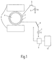
- the MR device shown purely schematically in FIG. 1 for MR examinations utilizing the Overhauser effect contains a magnet 3 for generating a homogeneous, stationary magnetic field in an examination area in which an object 4 to be examined, for example the skull of a patient, can be located. Due to the exploitation of the Overhauser effect, the field strength of the stationary magnetic field can be significantly lower than is usual with MR devices, eg 15 mT.
- the MR coil arrangement 1 can be operated with a spectrometer 9 via the switch 8 be connected to the received MR signals for a reconstruction unit 10 prepared, which reconstructs an MR image of the examination area.
- the ESR coil arrangement 2 is used first Electron spin resonance saturated by free electrons that are in an object 4 injected solution are included. Then the nuclear magnetization in the Inspection area excited by the MR coil assembly 1, after which the Switch 8 is switched and received by the MR coil assembly MR signals are processed by the spectrometer 9.
- FIG. 2 and 3 show a first embodiment of the combination of Coil arrangements 1, 2, FIG. 3 a view of the line in FIG. 2 A-A 'defined cross section.
- the MR coil arrangement 1 consists of a coil whose turns 101 in a first plane from the outside in a spiral are wound inwards and their windings 102 (in Fig. 2 with thin lines shown) in a second level from the inside to the outside on a winding body 103 are wound.
- the input connections of this MR coil are 104 designated.
- the MR coil can be made from a suitable copper braid to to achieve the required goodness.
- the ESR coil 2 concentrically has two in a plane above the MR coil Axis of symmetry 11 arranged circular conductor loops 210 and 220 on and in a second level below the MR coil 1 (the two levels can be defined by the surface of two carrier bodies, not shown his) two concentrically arranged conductor loops 230 and 240.
- the four Conductor loops 210 ... 240 thus form a rectangle in cross section, in the practically field-free center is the MR coil. That is why the MR coil 1 on the ESR coil 2 practically no influence.
- the conductor loops 210 ... 240 are interrupted at regular intervals along the circumference, so that galvanically separated conductor sections are formed which are short in comparison to a quarter of the wavelength at the frequency f 1 . These conductor sections are connected to one another via capacitors 203, the capacitance of which is measured such that each of the conductor loops is in resonance at the frequency f 1 .
- the bridging elements 230 are indicated by a bold line in FIG. 2, but, as can be seen from FIG. 3, they can contain a capacitor 231 in addition to a conductor 232. Its capacitance is such that the bridging elements represent a short circuit for the frequency f 1 and a relatively high impedance for the frequency f 2 , which the eddy currents caused by the MR coil - or the gradient coils required for imaging - in the ESR coil dampens. It is not necessary for each bridging element to contain a capacitor 231, as shown in FIG. 3. However, there must be at least one capacitor in each loop consisting of two conductors and the bridging members 230 connecting them; otherwise the eddy currents generated by the MR coil arrangement 1 in these meshes would significantly reduce the quality of the MR coil.
- FIG. 2 Several of the ones shown in FIG. 2 can also be used for the examination Coil arrangements are used, the received MR signals being separated processed and combined into a single MR image.
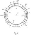
- FIGS. Another embodiment of the invention is shown in FIGS. While in the first embodiment, the conductors of the MR or ESR coil in one or two levels are arranged, this is the second Embodiment around a (cylindrical) volume coil arrangement, the one three-dimensional examination area can include.
- Fig. 4 represents one Front view (seen in the direction of the cylinder axis 11), while FIG. excerpts - representation of a plan view (perpendicular to the cylinder axis 11). 6 shows sections of the coil arrangement in an axis of symmetry 11 vertical cross section, which is defined by the arrows B - B 'in Fig. 5.
- the MR coil arrangement comprises two saddle coils offset by 90 ° from one another 130,140, which can be operated as quadrature coils and of which the Saddle coil 140 on the outer surface of an insulating support body 110, e.g. out Plastic, is attached while the saddle coil 130 with the inner surface of the Carrier body is connected.
- an insulating support body 110 e.g. out Plastic
- the saddle coils have an arcuate shape enclosing the cylinder axis 11 Part and a part running parallel to the cylinder axis.
- Fig. 5 shows furthermore, that each saddle coil 130, 140 has several turns (FIG. 5 shows only two turns), which coincides with the turns of the other coils or overlap less.
- a cylindrical support body 206 belongs to the ESR coil arrangement the carrier body 110 is enclosed and a carrier body 207 which the Encloses carrier body 110.
- the four ring-shaped conductor loops close the arc-shaped ones Sections of the saddle coils.
- the arches will be at the other end of the saddle spool in the same way from conductor loops (not shown) of the ESR coil locked in.
- the conductor loops 210 ... 240 are in the same way as those in FIGS. 2 and 3 illustrated embodiment by not shown Connection capacitors interrupted, so that there are conductor loop sections result that are shorter than 1/4 of the wavelength of the ESR frequency.
- the circular coils shown in the drawing can also differently shaped coils - e.g. rectangular or elliptical - can be used.
- 1 acts as a transmitting and as the MR coil Receiving coil.
- it can also be a separate MR coil as a transmission coil are used, which the coil arrangement shown in the drawings encloses, e.g. a saddle coil.
- the signal / noise ratio can be improved.
Abstract
Description
Die Erfindung betrifft ein MR-Gerät, wobei ein stationäres Magnetfeld auf einen Untersuchungsbereich einwirkt, mit einer ESR-Spulenanordnung zum Erzeugen eines Hochfrequenz-Magnetfeldes bei einer ersten Frequenz und einer bei einer zweiten Frequenz arbeitenden MR-Spulenanordnung. Außerdem bezieht sich die Erfindung auf eine für ein solches MR-Gerät geeignete Spulenanordnung.The invention relates to an MR device, wherein a stationary magnetic field on a Examination area acts, with an ESR coil arrangement for generating a High frequency magnetic field at a first frequency and one at a second Frequency working MR coil arrangement. The invention also relates to a coil arrangement suitable for such an MR device.
Wenn die Elektronenspinresonanz (ESR) von in Lösungen enthaltenen freien Elektronen gesättigt und erst danach darin die Kernmagnetisierung angeregt wird, ergibt sich eine erhebliche Anhebung der Amplitude des durch die Anregung der Kernmagnetisierung erzeugten MR-Signals (MR=Magnetresonanz). Auf diese Weise ist es möglich, Bilder mit hoher Qualität auch bei niedrigen Feldstärken des stationäre Magnetfeldes zu erhalten. Dieser Effekt wird allgemein als Overhauser-Effekt bezeichnet.When the electron spin resonance (ESR) of free contained in solutions Electrons saturated and only afterwards the nuclear magnetization is excited, there is a significant increase in the amplitude of the excitation of the Nuclear magnetization generated MR signal (MR = magnetic resonance). In this way it is possible to get high quality images even at low field strengths to obtain a stationary magnetic field. This effect is commonly called the Overhauser effect designated.
Die erste Frequenz (der ESR) ist - bei gleichem stationären Magnetfeld - um einen Faktor 660 größer als die zweite Frequenz (der MR). Es ist sehr schwierig, eine einzelne Spule zu schaffen, die bei diesen beiden Frequenzen optimale Eigenschaften hat. Benutzt man hingegen für ESR und MR zwei getrennte Spulenanordnungen, muß die Wechselwirkung zwischen den Spulen in Betracht gezogen werden.The first frequency (the ESR) is - with the same stationary magnetic field - around one Factor 660 greater than the second frequency (the MR). It is very difficult to find one single coil to create the optimal properties at these two frequencies Has. On the other hand, if two separate coil arrangements are used for ESR and MR, the interaction between the coils must be taken into account.
Ordnet man etwa eine MR-Spule im Innern einer ESR-Spule an, dann wird das Hochfrequenz-Magnetfeld der ESR-Spule durch die MR-Spule abgeschirmt. Aufgrund der Streukapazität zwischen den Spulenwindungen ergeben sich in der MR-Spule Mehrfachresonanzen. - Ordnet man hingegen die ESR-Spule im Innern der MR-Spule an, dann kann die Wechselwirkung zwischen den Spulen gering sein, wenn der Durchmesser der MR-Spule mehrfach so groß ist wie der der ESR-Spule - wie bei dem in J. Magn. Reson. 76, 366-370, (1988) beschriebenen MR-Gerät. Die MR-Spule hat dabei jedoch einen so großen Abstand vom Untersuchungsbereich im Innern der ESR-Spule, daß damit - zumindest für die medizinische bildgebende Diagnostik - kein brauchbares Signal/Rauschverhältnis erreicht werden kann.If you arrange an MR coil inside an ESR coil, for example, that will be High-frequency magnetic field of the ESR coil shielded by the MR coil. Due to the stray capacitance between the coil turns in the MR coil multiple resonances. - However, if you arrange the ESR coil inside the MR coil, then the interaction between the coils can be small, if the diameter of the MR coil is several times that of the ESR coil - as in the case in J. Magn. Reson. 76, 366-370, (1988) MR device. The However, the MR coil has such a large distance from the examination area in the Inside the ESR coil that so - at least for medical imaging Diagnostics - no usable signal / noise ratio can be achieved.
Aufgabe der vorliegenden Erfindung ist es daher, ein MR-Gerät der eingangs genannten Art so zu verbessern, daß sich nur noch geringe Wechselwirkungen zwischen der ESR-Spulenanordnung und der MR-Spulenanordnung ergeben.The object of the present invention is therefore an MR device of the beginning to improve the type mentioned so that there are only minor interactions between the ESR coil arrangement and the MR coil arrangement.
Diese Aufgabe wird erfindungsgemäß dadurch gelöst, daß die ESR-Spulenanordnung
zumindest zwei gleichartig geformte Leiterschleifen umfaßt, die bei der Erzeugung
des Hochfrequenz-Magnetfeldes von einander entsprechenden Strömen mit gleichem
Umlaufsinn durchflossen werden, und daß der (bzw. die) Leiter der MR-Spulenanordnung
in dem vom Hochfrequenz-Magnetfeld der ESR-Spulenanordnung
im wesentlichen freien Raum zwischen den Leiterschleifen angeordnet ist (sind).
Eine dafür geeignete Spulenanordnung ist in Anspruch 7 angegeben.This object is achieved in that the ESR coil arrangement
comprises at least two identically shaped conductor loops that are used in the production
of the high-frequency magnetic field from corresponding currents with the same
Flow direction and that the (or) the head of the MR coil arrangement
in the high-frequency magnetic field of the ESR coil arrangement
substantially free space is (are) arranged between the conductor loops.
A suitable coil arrangement is specified in
Die Erfindung basiert auf folgender Überlegung: Bei einer ESR-Spulenanordnung aus mehreren gleichartig geformten Leiterschleifen, die von einander entsprechenden Strömen mit gleichem Umlaufsinn durchflossen werden, gibt es in deren Zentrum einen Bereich, in dem sich die Hochfrequenz-Magnetfelder der Leiterschleifen der ESR-Spulen praktisch kompensieren. Umgekehrt haben die mit den in diesem Bereich befindlichen Leitern der MR-Spulenanordnung verknüpften Magnetfelder auf die ESR-Spulenanordnung keinen Einfluß. Die ESR-Spulenanordnung "sieht" also die MR-Spulenanordnung nicht. Andererseits wirken die Leiterschleifen der ESR-Spulenanordnung auf die MR-Spulenanordnung wie eine Abschirmung, die jedoch relativ offen ist, so daß die Güte der MR-Spulenanordnung dadurch nur relativ geringfügig reduziert wird. Wenn sehr viele gleichartig geformte Leiterschleifen vorgesehen sind, ergibt sich die Wirkung eines Faraday-Käfigs. The invention is based on the following consideration: With an ESR coil arrangement from several similarly shaped conductor loops, which correspond to each other Flows with the same sense of circulation flow through the center an area in which the high-frequency magnetic fields of the conductor loops of the Practically compensate ESR coils. Conversely, those with those in this Magnetic fields linked to the area of the conductors of the MR coil arrangement the ESR coil arrangement has no influence. The ESR coil arrangement therefore "sees" the MR coil arrangement is not. On the other hand, the conductor loops of the ESR coil arrangement act to the MR coil assembly like a shield, however is relatively open, so that the quality of the MR coil arrangement is only relative is slightly reduced. If there are a large number of identical conductor loops are intended, the effect of a Faraday cage results.
Die in Anspruch 2 angegebene Ausgestaltung mit (zumindest) vier Leiterschleifen
hat gegenüber einer Anordnung mit nur zwei Leiterschleifen den Vorteil, daß der
Bereich in dem die MR-Spulenanordnung die ESR-Spulenanordnung nur geringfügig
beeinflußt größer ist.The embodiment specified in
Durch die Ausgestaltung nach Anspruch 3 wird ein einwandfreies Funktionieren der
ESR-Spulenanordnung auch dann sichergestellt, wenn die Länge der ESR-Spule ein
Viertel der Wellenlänge der ESR-Schwingung - oder mehr - beträgt. Voraussetzung
ist, daß die Länge der durch die Verbindungskondensatoren galvanisch voneinander
getrennten Leiterabschnitte klein ist im Vergleich zu einem Viertel der Wellenlänge
der ESR-Schwingung.The embodiment according to
Die gemäß Anspruch 4 vorgesehene Überbrückungsglieder stellen einerseits sicher
daß die Ströme in allen Leiterschleifen der ESR-Spulenanordnung gleichphasig
bleiben. Andererseits werden Wirbelströme, die von der MR-Spulenanordnung oder
den zur Bildgebung erforderlichen Gradientenspulen hervorgerufen werden
gedämpft.The bridging elements provided according to
Wenn die Leiter der MR-Spulenanordnung jeweils zwischen mindestens zwei gleichartig geformten Leiterschleifen der ESR-Spulenanordnung liegen, liegt es nahe, daß beide Spulenanordnungen vom gleichen Typ sind. Gemäß Anspruch 5 kann die MR-Spulenanordnung aber auch eine oder mehrere Sattelspulen enthalten, während die ESR-Spulenanordnung vom sogenannten Birdcage-Typ ist, bei dem zwei kreisförmige Leiterabschnitte über gerade Leiterabschnitte miteinander verbunden sind. Bei der dabei möglichen weiteren Ausgestaltung nach Anspruch 6 schließen die geraden Leiterabschnitte der ESR-Spule zwischen sich die Leiter zweier (oder mehrerer) MR-Spulen ein.If the conductors of the MR coil arrangement are each between at least two there are similarly shaped conductor loops of the ESR coil arrangement suggests that both coil assemblies are of the same type. According to claim 5 the MR coil arrangement can also contain one or more saddle coils, while the ESR coil arrangement is of the so-called birdcage type, in which two circular conductor sections over straight conductor sections with each other are connected. In the possible further embodiment according to claim 6 the straight conductor sections of the ESR coil close the conductors between them two (or more) MR coils.
Die Erfindung wird nachstehend anhand der Zeichnungen näher erläutert. Es zeigen:
Das in Fig. 1 rein schematisch dargestellte MR-Gerät für MR-Untersuchungen unter
Ausnutzung des Overhauser Effektes enthält einen Magneten 3 zur Erzeugung eines
homogenen, stationären Magnetfeldes in einem Untersuchungsbereich in dem sich
ein zu untersuchendes Objekt 4 z.B. der Schädel eines Patienten befinden kann.
Wegen der Ausnutzung des Overhauser Effektes kann die Feldstärke des stationären
Magntfeldes wesentlich geringer sein, als sonst bei MR-Geräten üblich, z.B. 15 mT.
Auf den Untersuchungsbereich wirkt außerdem eine in Fig. 1 nur schematisch
dargestellte Kombination aus einer MR-Spulenanordnung 1 (gestrichelt angedeutet)
und einer ESR-Spulenanordnung 2 ein. Eine erste Hochfrequenz-Stromquelle 6
liefert über einen Schalter 5 an die ESR-Spulenanordnung 2 einen
Hochfrequenzstrom mit einer ersten Frequenz
f1 = 226 Mhz, während eine zweite Hochfrequenz-Stromquelle 7 der MR-Spulenanordnung
1 über einen Umschalter 8 einen Hochfrequenzstrom mit einer
zweite Frequenz f2 = 600 kHz liefert.The MR device shown purely schematically in FIG. 1 for MR examinations utilizing the Overhauser effect contains a
Über den Umschalter 8 kann die MR-Spulenanordnung 1 mit einem Spektrometer 9
verbunden werden, das die empfangenen MR-Signale für eine Rekonstruktionseinheit
10 aufbereitet, die daraus ein MR-Bild des Untersuchungsbereiches rekonstruiert.The
Bei einer Untersuchung wird zunächst mittels der ESR-Spulenanordnung 2 die
Elektronenspinresonanz von freien Elektronen gesättigt, die in einer in das Objekt 4
injizierten Lösung enthalten sind. Danach wird die Kernmagnetisierung im
Untersuchungsbereich durch die MR-Spulenanordnung 1 angeregt, wonach der
Umschalter 8 umgeschaltet wird und die von der MR-Spulenanordnung empfangenen
MR-Signale von dem Spektrometer 9 verarbeitet werden.In an investigation, the
Die Figuren 2 und 3 zeigen eine erste Ausführungsform der Kombination der
Spulenanordnungen 1,2, wobei Fig. 3 eine Ansicht des in Fig. 2 durch die Linien
A-A' definierten Querschnitts darstellt. Die MR-Spulenanordnung 1 besteht aus
einer Spule, deren Windungen 101 in einer ersten Ebene von spiralförmig von außen
nach innen gewickelt sind und dessen Windungen 102 (in Fig. 2 mit dünnen Linien
dargestellt) in einer zweiten Ebene von innen nach außen auf einen Wickelkörper
103 gewickelt sind. Die Eingangsanschlüsse dieser MR-Spule sind mit 104
bezeichnet. Die MR-Spule kann aus einer geeigneten Kupferlitze hergestellt sein, um
die erforderliche Güte zu erreichen.Figures 2 and 3 show a first embodiment of the combination of
Die ESR-Spule 2 weist in einer Ebene oberhalb der MR-Spule zwei konzentrisch zur
Symmetrieachse 11 angeordnete kreisförmige Leiterschleifen 210 und 220 auf und in
einer zweiten, unterhalb der MR-Spule 1 befindlichen Ebene (die beiden Ebenen
können durch die Oberfläche von zwei nicht dargestellten Trägerkörpern definiert
sein) zwei konzentrisch angeordnete Leiterschleifen 230 und 240. Die vier
Leiterschleifen 210...240 bilden somit im Querschnitt ein Rechteck, in dessen
praktisch feldfreien Zentrum sich die MR-Spule befindet. Deshalb hat die MR-Spule
1 auf die ESR-Spule 2 praktisch keinen Einfluß.The
Die Leiterschleifen 210...240 sind längs des Umfangs in regelmäßigen Abständen
unterbrochen, so daß voneinander galvanisch getrennte Leiterabschnitte entstehen,
die kurz sind im Vergleich zu einem Viertel der Wellenlänge bei der Frequenz f1.
Diese Leiterabschnitte sind über Kondensatoren 203 miteinander verbunden, deren
Kapazität so gemessen ist, daß jede der Leiterschleifen bei der Frequenz f1 in
Resonanz ist. The
Um die Wechselwirkung zwischen der ESR-Spule und der MR-Spule klein zu
halten, müssen die Ströme in den vier Leiterschleifen entlang des Umfangs jeweils
die gleiche Phasenlage aufweisen. Um dies sicherzustellen, sind die verschiedenen
Leiterschleifen 210...240 in regelmäßigen Abständen - z.B. vor und hinter den
Unterbrechungen, sowie in der Mitte dazwischen - durch Überbrückungsglieder 230
überbrückt. Die vier durch die Überbrückungsglieder parallel geschaltenen
Leiterschleifen bilden eine ESR-Spule mit einer einzigen Windung, deren
Eingangsanschlüsse mit 204 bezeichnet sind.To make the interaction between the ESR coil and the MR coil small
hold the currents in the four conductor loops along the circumference each
have the same phase position. To ensure this, there are
Die Überbrückungsglieder 230 sind in Fig. 2 durch eine fette Linie angedeutet,
jedoch können sie, wie aus Fig. 3 ersichtlich, neben einem Leiter 232 einen
Kondensator 231 enthalten. Dessen Kapazität ist so bemessen, daß die
Überbrückungsglieder für die Frequenz f1 einen Kurzschluß darstellen und für die
Frequenz f2 eine relativ hohe Impedanz, die die von der MR-Spule - oder den zur
Bildgebung erforderlichen Gradientenspulen - hervorgerufenen Wirbelströme in der
ESR-Spule dämpft. Dabei muß nicht jedes Überbrückungsglied einen Kondensator
231 enthalten, wie in Fig. 3 dargestellt. Jedoch muß in jeder aus zwei Leitern und
den sie verbindenden Überbrückungsgliedern 230 bestehenden Schleife mindestens
ein Kondensator vorhanden sein; anderenfalls würden die von der MR-Spulenanordnung
1 erzeugten Wirbelströme in diesen Maschen die Güte der MR-Spule
deutlich reduzieren.The
Es können zur Untersuchung auch mehrere der in Fig. 2 dargestellten Spulenanordnungen verwendet werden, wobei die empfangenen MR-Signale getrennt verarbeitet und zu einem einzigen MR-Bild kombiniert werden können.Several of the ones shown in FIG. 2 can also be used for the examination Coil arrangements are used, the received MR signals being separated processed and combined into a single MR image.
In den Figuren 4 bis 6 ist eine andere Ausführungsform der Erfindung dargestellt.
Während bei der ersten Ausführungsform die Leiter der MR- bzw. der ESR-Spule in
einer bzw. zwei Ebenen angeordnet sind, handelt es sich bei dieser zweiten
Ausführungsform um eine (zylinderförmige) Volumenspulenanordnung, die einen
dreidimensionalen Untersuchungsbereich einschließen kann. Fig. 4 stellt dabei eine
Stirnansicht (in Richtung der Zylinderachse 11 gesehen) dar, während Fig. 5 eine -
ausschnittsweise - Darstellung einer Draufsicht (senkrecht zur Zylinderachse 11) ist.
Fig. 6 stellt die Spulenanordnung ausschnittsweise in einem zur Symmetrieachse 11
senkrechten Querschnitt dar, der durch die Pfeile B - B' in Fig. 5 definiert ist.Another embodiment of the invention is shown in FIGS.
While in the first embodiment, the conductors of the MR or ESR coil in
one or two levels are arranged, this is the second
Embodiment around a (cylindrical) volume coil arrangement, the one
three-dimensional examination area can include. Fig. 4 represents one
Front view (seen in the direction of the cylinder axis 11), while FIG.
excerpts - representation of a plan view (perpendicular to the cylinder axis 11).
6 shows sections of the coil arrangement in an axis of
Die MR-Spulenanordnung umfaßt zwei um 90° gegeneinander versetzte Sattelspulen
130,140, die als Quadraturspulen betrieben werden können und von denen die
Sattelspule 140 auf der Außenfläche eines isolierenden Trägerkörpers 110, z.B. aus
Kunststoff, angebracht ist, während die Sattelspule 130 mit der Innenfläche des
Trägerkörpers verbunden ist.The MR coil arrangement comprises two saddle coils offset by 90 ° from one another
130,140, which can be operated as quadrature coils and of which the
Die Sattelspulen haben einen die Zylinderachse 11 umschließenden bogenförmigen
Teil und einen zur Zylinderachse parallel verlaufenden Teil. Fig. 5 zeigt
darüberhinaus, daß jede Sattelspule 130, 140 mehrere Windungen (Fig. 5 zeigt nur
zwei Windungen) aufweist, die sich mit den Windungen der anderen Spulen mehr
oder weniger überlappen.The saddle coils have an arcuate shape enclosing the
Zur ESR-Spulenanordnung gehört ein zylinderförmiger Trägerkörper 206, der von
dem Trägerkörper 110 umschlossen wird und ein Trägerkörper 207, der den
Trägerkörper 110 umschließt. Auf dem vorderen Teil der Trägerkörper 206, 207
befinden sich - in axialer Richtung gegeneinander versetzt - zwei Leiterschleifen 210
und 230 (letztere nicht dargestellt), und ebenso befinden sich auf dem Trägerkörper
207 zwei in axialer Richtung gegeneinander versetzte Leiterschleifen 220 und 240
(vgl. Fig. 5). Die vier ringförmigen Leiterschleifen schließen die bogenförmigen
Abschnitte der Sattelspulen ein. Die Bögen am anderen Ende der Sattelspule werden
auf gleiche Weise von nicht näher dargestellten Leiterschleifen der ESR-Spule
eingeschlossen. A
Die Leiterschleifen 210...240 sind in gleicher Weise wie bei den in Fig. 2 und 3
dargestellten Ausführungsbeispiel durch nicht näher dargestellte
Verbindungskondensatoren unterbrochen, so daß sich Leiterschleifenabschnitte
ergeben, die kürzer sind als 1/4 der Wellenlänge der ESR-Frequenz.The
Beiderseits der vier auf dem Umfang gegeneinander versetzten Bereiche, in denen
sich die Sattelspulen 130, 140 überlappen, sind Überbrückungsglieder 230
vorgesehen (Fig.4). Auch die sich geradlinig erstreckenden Abschnitte der
Sattelspulen werden von zwei geradlinigen Leiterschleifen 250, 260 auf den äußeren
Trägerkörper 207 und 270, 280 auf dem inneren Trägerkörper 206 eingeschlossen,
wie sich aus Fig. 5 und insbesondere Fig. 6 ergibt. Somit sind alle Teile der beiden
Sattelspulen von je vier Leiterschleifen der ESR-Spulenanordnung eingeschlossen.On both sides of the four circumferentially offset areas in which
the saddle coils 130, 140 overlap are bridging
Durch die ringförmigen Leiterschleifen der ESR-Spulenanordnung an den Stirnseiten
und durch die sie verbindenden geradlinigen Leiterschleifen 250...280 ergibt sich
eine ESR-Spule vom sogenannten Birdcage-Typ, wobei jedoch alle Leiter vierfach
vorhanden sind. Allerdings hätte eine solche Birdcage-Spule nur vier auf dem
Umfang um 90° gegeneinander versetzte stabförmige Leiterschleifen. Um eine
verbesserte Empfindlichkeit der ESR-Spule zu erreichen, können vier weitere
derartiger stabförmiger Leiterschleifen (nicht dargestellt) vorgesehen sein, die
gegenüber den Überlappungsbereichen um jeweils 45° versetzt sind und die die dort
vorgesehenen zusätzlichen Überbrückungsglieder 235 an deren Enden senkrecht zur
Zeichenebene der Fig. 4 fortsetzen.Due to the ring-shaped conductor loops of the ESR coil arrangement on the front sides
and the straight-
Anstelle der in der Zeichnung dargestellten kreisförmigen Spulen können auch anders geformte Spulen - z.B rechteckig oder elliptische - benutzt werden. Bei dem Ausführungsbeispiel nach Fig. 1 fungiert die MR-Spule als Sende- und als Empfangsspule. Es kann aber auch eine gesonderte MR-Spule als Sende-Spule benutzt werden, welche die in den Zeichnungen dargestellte Spulenanordnung umschließt, z.B. eine Sattelspule. Mit einer Kühlung zumindest der MR-Empfangsspule - z.B mit flüssigem Stickstoff - kann das Signal/Rauschverhältnis verbessert werden.Instead of the circular coils shown in the drawing can also differently shaped coils - e.g. rectangular or elliptical - can be used. In which 1 acts as a transmitting and as the MR coil Receiving coil. But it can also be a separate MR coil as a transmission coil are used, which the coil arrangement shown in the drawings encloses, e.g. a saddle coil. With cooling of at least the MR receiving coil - e.g. with liquid nitrogen - the signal / noise ratio can be improved.
Claims (7)
dadurch gekennzeichnet, daß die ESR-Spulenanordnung (2) zumindest zwei gleichartig geformte Leiterschleifen (210, 220) umfaßt, die bei der Erzeugung des Hochfrequenz-Magnetfeldes von einander entsprechenden Strömen mit gleichem Umlaufsinn durchflossen werden, und daß der (bzw die) Leiter der MR-Spulenanordnung (101,102) in dem vom Hochfrequenz-Magnetfeld der ESR-Spulenanordnung (2) im wesentlichen freien Raum zwischen den Leiterschleifen angeordnet ist (sind).MR device, a stationary magnetic field acting on an examination area, with an ESR coil arrangement (2) for generating a high-frequency magnetic field at a first frequency and an MR coil arrangement (1) operating at a second frequency,
characterized in that the ESR coil arrangement (2) comprises at least two identically shaped conductor loops (210, 220) which are flowed through by corresponding currents with the same sense of rotation during the generation of the high-frequency magnetic field, and in that the conductor (s) MR coil arrangement (101, 102) in which there is (are) essentially free space between the conductor loops from the high-frequency magnetic field of the ESR coil arrangement (2).
dadurch gekennzeichnet, daß die ESR-Spulenanordnung (2) zumindest vier Leiterschleifen (210.....240) umfaßt.MR device according to claim 1,
characterized in that the ESR coil arrangement (2) comprises at least four conductor loops (210 ..... 240).
dadurch gekennzeichnet, daß die Leiterschleifen (210, 220) der ESR-Spulenanordnung aus Leiterabschnitten bestehen, die über Verbindungs-Kondensatoren (203) elektrisch miteinander verbunden sind.MR device according to claim 1,
characterized in that the conductor loops (210, 220) of the ESR coil arrangement consist of conductor sections which are electrically connected to one another via connecting capacitors (203).
dadurch gekennzeichnet, daß einander benachbarte Leiterschleifen (210, 220) der ESR-Spulenanordnung durch Überbrückungsglieder überbrückt sind, die ein Leiterstück (231) und/oder einen Überbrückungs-Kondensator (232) enthalten, daß die durch Teile zweier Leiterschleifen (210, 220) und durch zwei Überbrückungsglieder (230) gebildeten Maschen mindestens einen Überbrückungskondensator (232) umfassen, und daß die Kapazität der Überbrückungskondensatoren so bemessen ist, daß sie eine niedrige Impedanz für die erste Frequenz und eine zur Dämpfung von Wirbelströmen der zweiten Frequenz hinreichend große Impedanz aufweisen.MR device according to claim 1,
characterized in that mutually adjacent conductor loops (210, 220) of the ESR coil arrangement are bridged by bridging elements which contain a conductor piece (231) and / or a bridging capacitor (232), that by parts of two conductor loops (210, 220) and comprising at least one bridging capacitor (232) formed by two bridging elements (230), and that the capacitance of the bridging capacitors is dimensioned such that they have a low impedance for the first frequency and a sufficiently high impedance to damp eddy currents of the second frequency.
dadurch gekennzeichnet, daß die MR-Spulenanordnung (1) mindestens eine Sattelspule (130, 140) aufweist mit eine Achse (11) bogenförmig umgebenden Segmenten, die über zur Achse parallele Segmente miteinander verbunden sind und daß die ESR-Spulenanordnung (2) vom Birdcage-Typ ist, deren kreisförmige Leiterabschnitte (210.....24) die bogenförmigen Segmente und deren gerade Leiterabschnitte (250....280) die parallelen Segmente der MR-Spulenanordnung einschließen.MR device according to claim 1,
characterized in that the MR coil arrangement (1) has at least one saddle coil (130, 140) with segments surrounding an axis (11) in an arcuate manner, which are connected to one another via segments parallel to the axis, and in that the ESR coil arrangement (2) from birdcage -Type is, whose circular conductor sections (210 ..... 24) enclose the arcuate segments and whose straight conductor sections (250 .... 280) enclose the parallel segments of the MR coil arrangement.
dadurch gekennzeichnet, daß die MR-Spulenanordnung mehrere gegeinander versetzte und den gleichen Abschnitt (11) der Achse umschließende Sattelspulen (130) umfaßt und daß die geraden Leiterabschnitte (250....280) der ESR-Spulenanordnung je ein zur Achse paralleles Segment von wenigstens zwei Sattelspulen (130, 140) einschließen.MR device according to claim 5,
characterized in that the MR coil arrangement comprises a plurality of saddle coils (130) which are offset with respect to one another and surround the same section (11) of the axis, and in that the straight conductor sections (250 .... 280) of the ESR coil arrangement each have a segment parallel to the axis of include at least two saddle coils (130, 140).
dadurch gekennzeichnet, daß die ESR-Spulenanordnung (2) zumindest zwei gleichartig geformte Leiterschleifen (210, 220) umfaßt, die bei der Erzeugung des Hochfrequenz-Magnetfeldes von einander entsprechenden Strömen mit gleichem Umlaufsinn durchflossen werden, und daß der (bzw die) Leiter der MR-Spulenanordnung (101,102) in dem vom Hochfrequenz-Magnetfeld der ESR-Spulenanordnung (2) im wesentlichen freien Raum zwischen den Leiterschleifen angeordnet ist (sind).Coil arrangement with an ESR coil arrangement (2) for generating a high-frequency magnetic field at a first frequency and an MR coil arrangement (1) operating at a second frequency,
characterized in that the ESR coil arrangement (2) comprises at least two identically shaped conductor loops (210, 220) which are flowed through by corresponding currents with the same sense of rotation during the generation of the high-frequency magnetic field, and in that the conductor (s) MR coil arrangement (101, 102) in which there is (are) essentially free space between the conductor loops from the high-frequency magnetic field of the ESR coil arrangement (2).
Applications Claiming Priority (2)
| Application Number | Priority Date | Filing Date | Title |
|---|---|---|---|
| DE19740375 | 1997-09-13 | ||
| DE1997140375 DE19740375A1 (en) | 1997-09-13 | 1997-09-13 | MR device for Overhauser imaging processes |
Publications (2)
| Publication Number | Publication Date |
|---|---|
| EP0902299A2 true EP0902299A2 (en) | 1999-03-17 |
| EP0902299A3 EP0902299A3 (en) | 2000-03-15 |
Family
ID=7842299
Family Applications (1)
| Application Number | Title | Priority Date | Filing Date |
|---|---|---|---|
| EP98202989A Withdrawn EP0902299A3 (en) | 1997-09-13 | 1998-09-07 | MR device for Overhauser imaging methods |
Country Status (3)
| Country | Link |
|---|---|
| EP (1) | EP0902299A3 (en) |
| JP (1) | JPH11142495A (en) |
| DE (1) | DE19740375A1 (en) |
Cited By (2)
| Publication number | Priority date | Publication date | Assignee | Title |
|---|---|---|---|---|
| CN103027679A (en) * | 2011-10-04 | 2013-04-10 | 西门子公司 | Method for the control of a magnetic resonance system |
| WO2016161278A1 (en) * | 2015-04-01 | 2016-10-06 | The General Hospital Corporation | System and method for imaging nanodiamonds as dynamic nuclear polarization agent |
Families Citing this family (3)
| Publication number | Priority date | Publication date | Assignee | Title |
|---|---|---|---|---|
| JP4419954B2 (en) * | 2003-02-10 | 2010-02-24 | 日立金属株式会社 | Magnetic field generator |
| JP5973397B2 (en) * | 2013-08-30 | 2016-08-23 | 日本電信電話株式会社 | Electron spin resonance device |
| CN110618464A (en) * | 2019-06-28 | 2019-12-27 | 中国地质大学(武汉) | System and method for improving Larmor precession signal-to-noise ratio of Overhauser magnetic sensor |
Citations (2)
| Publication number | Priority date | Publication date | Assignee | Title |
|---|---|---|---|---|
| EP0365065A1 (en) * | 1985-09-20 | 1990-04-25 | Btg International Limited | Magnetic field screens |
| US5621322A (en) * | 1994-03-09 | 1997-04-15 | Picker Nordstar Inc. | VHF/RF volume antenna for magnetic resonance imaging including VHF applicator and RF coil arranged to provide perpendicular fields |
-
1997
- 1997-09-13 DE DE1997140375 patent/DE19740375A1/en not_active Withdrawn
-
1998
- 1998-09-07 EP EP98202989A patent/EP0902299A3/en not_active Withdrawn
- 1998-09-10 JP JP10256858A patent/JPH11142495A/en active Pending
Patent Citations (2)
| Publication number | Priority date | Publication date | Assignee | Title |
|---|---|---|---|---|
| EP0365065A1 (en) * | 1985-09-20 | 1990-04-25 | Btg International Limited | Magnetic field screens |
| US5621322A (en) * | 1994-03-09 | 1997-04-15 | Picker Nordstar Inc. | VHF/RF volume antenna for magnetic resonance imaging including VHF applicator and RF coil arranged to provide perpendicular fields |
Cited By (4)
| Publication number | Priority date | Publication date | Assignee | Title |
|---|---|---|---|---|
| CN103027679A (en) * | 2011-10-04 | 2013-04-10 | 西门子公司 | Method for the control of a magnetic resonance system |
| CN103027679B (en) * | 2011-10-04 | 2016-02-17 | 西门子公司 | For controlling the method for magnetic resonance system |
| US9547064B2 (en) | 2011-10-04 | 2017-01-17 | Siemens Aktiengesellschaft | Method for the control of a magnetic resonance system |
| WO2016161278A1 (en) * | 2015-04-01 | 2016-10-06 | The General Hospital Corporation | System and method for imaging nanodiamonds as dynamic nuclear polarization agent |
Also Published As
| Publication number | Publication date |
|---|---|
| EP0902299A3 (en) | 2000-03-15 |
| DE19740375A1 (en) | 1999-03-18 |
| JPH11142495A (en) | 1999-05-28 |
Similar Documents
| Publication | Publication Date | Title |
|---|---|---|
| EP0803736B1 (en) | MR apparatus with cylindrical coil means and with surface coil means | |
| EP0073402B1 (en) | Gradient coil system for a nuclear magnetic-resonance technique device | |
| DE4422782C2 (en) | Actively shielded transverse gradient coil for magnetic resonance imaging devices | |
| DE60026795T2 (en) | Device magnetic resonance | |
| EP0200078B1 (en) | Apparatus for nuclear tomography | |
| DE19702256A1 (en) | MR device with an MR coil arrangement | |
| DE3133432A1 (en) | HIGH-FREQUENCY FIELD DEVICE IN A NUCLEAR RESONANCE APPARATUS | |
| DE4029477A1 (en) | Tesseral gradient coil for nuclear spin tomography device | |
| EP0142077B1 (en) | High-frequency device in a nuclear-spin resonance apparatus with a surface coil | |
| EP0197589A2 (en) | Coil arrangement for nuclear-spin inspections | |
| EP0141149A1 (en) | Magnet device for a nuclear spin resonance tomography system with a shielding arrangement | |
| DE10134171A1 (en) | High-frequency coil arrangement for an MR device | |
| EP0361190A1 (en) | Surface coil arrangement for examinations with the aid of nuclear magnetic resonance | |
| DE4024582A1 (en) | MRI | |
| DE102005033989A1 (en) | Nuclear magnetic resonance apparatus with Gradientenabschirmanordnung with reduced coupling to the resonator system | |
| DE10255261A1 (en) | RF coil arrangement for magnetic resonance imaging device | |
| EP0486086B1 (en) | Quadrature coils system | |
| EP0401917B1 (en) | High-frequency quadrature coil system | |
| EP0142079B1 (en) | High-frequency device in a nuclear-spin resonance apparatus | |
| EP0303095B1 (en) | Antenna for nmr spectrometer | |
| EP0281787A1 (en) | Surface resonator for a nuclear spin resonance apparatus | |
| EP0797103A1 (en) | MPI magnet assembly with two separated imaging volumes | |
| EP0902299A2 (en) | MR device for Overhauser imaging methods | |
| EP0177869B1 (en) | Magnet arrangement with a screen device for a nuclear spin tomography installation | |
| DE19535257A1 (en) | MR arrangement for determining the nuclear magnetization distribution with a surface coil arrangement |
Legal Events
| Date | Code | Title | Description |
|---|---|---|---|
| PUAI | Public reference made under article 153(3) epc to a published international application that has entered the european phase |
Free format text: ORIGINAL CODE: 0009012 |
|
| AK | Designated contracting states |
Kind code of ref document: A2 Designated state(s): AT BE CH CY DE DK ES FI FR GB GR IE IT LI LU MC NL PT SE |
|
| AX | Request for extension of the european patent |
Free format text: AL;LT;LV;MK;RO;SI |
|
| RAP3 | Party data changed (applicant data changed or rights of an application transferred) |
Owner name: KONINKLIJKE PHILIPS ELECTRONICS N.V. Owner name: PHILIPS CORPORATE INTELLECTUAL PROPERTY GMBH |
|
| PUAL | Search report despatched |
Free format text: ORIGINAL CODE: 0009013 |
|
| AK | Designated contracting states |
Kind code of ref document: A3 Designated state(s): AT BE CH CY DE DK ES FI FR GB GR IE IT LI LU MC NL PT SE |
|
| AX | Request for extension of the european patent |
Free format text: AL;LT;LV;MK;RO;SI |
|
| RIC1 | Information provided on ipc code assigned before grant |
Free format text: 7G 01R 33/62 A, 7G 01R 33/34 B |
|
| AKX | Designation fees paid | ||
| REG | Reference to a national code |
Ref country code: DE Ref legal event code: 8566 |
|
| STAA | Information on the status of an ep patent application or granted ep patent |
Free format text: STATUS: THE APPLICATION IS DEEMED TO BE WITHDRAWN |
|
| 18D | Application deemed to be withdrawn |
Effective date: 20000916 |