EP0904790A2 - Adjustabel injection length pen needle - Google Patents
Adjustabel injection length pen needle Download PDFInfo
- Publication number
- EP0904790A2 EP0904790A2 EP98307469A EP98307469A EP0904790A2 EP 0904790 A2 EP0904790 A2 EP 0904790A2 EP 98307469 A EP98307469 A EP 98307469A EP 98307469 A EP98307469 A EP 98307469A EP 0904790 A2 EP0904790 A2 EP 0904790A2
- Authority
- EP
- European Patent Office
- Prior art keywords
- extender
- pen needle
- hub
- needle assembly
- shield
- Prior art date
- Legal status (The legal status is an assumption and is not a legal conclusion. Google has not performed a legal analysis and makes no representation as to the accuracy of the status listed.)
- Granted
Links
Images


Classifications
-
- A—HUMAN NECESSITIES
- A61—MEDICAL OR VETERINARY SCIENCE; HYGIENE
- A61M—DEVICES FOR INTRODUCING MEDIA INTO, OR ONTO, THE BODY; DEVICES FOR TRANSDUCING BODY MEDIA OR FOR TAKING MEDIA FROM THE BODY; DEVICES FOR PRODUCING OR ENDING SLEEP OR STUPOR
- A61M5/00—Devices for bringing media into the body in a subcutaneous, intra-vascular or intramuscular way; Accessories therefor, e.g. filling or cleaning devices, arm-rests
- A61M5/46—Devices for bringing media into the body in a subcutaneous, intra-vascular or intramuscular way; Accessories therefor, e.g. filling or cleaning devices, arm-rests having means for controlling depth of insertion
-
- A—HUMAN NECESSITIES
- A61—MEDICAL OR VETERINARY SCIENCE; HYGIENE
- A61M—DEVICES FOR INTRODUCING MEDIA INTO, OR ONTO, THE BODY; DEVICES FOR TRANSDUCING BODY MEDIA OR FOR TAKING MEDIA FROM THE BODY; DEVICES FOR PRODUCING OR ENDING SLEEP OR STUPOR
- A61M5/00—Devices for bringing media into the body in a subcutaneous, intra-vascular or intramuscular way; Accessories therefor, e.g. filling or cleaning devices, arm-rests
- A61M5/178—Syringes
- A61M5/31—Details
- A61M5/32—Needles; Details of needles pertaining to their connection with syringe or hub; Accessories for bringing the needle into, or holding the needle on, the body; Devices for protection of needles
- A61M5/3205—Apparatus for removing or disposing of used needles or syringes, e.g. containers; Means for protection against accidental injuries from used needles
- A61M5/321—Means for protection against accidental injuries by used needles
- A61M5/3243—Means for protection against accidental injuries by used needles being axially-extensible, e.g. protective sleeves coaxially slidable on the syringe barrel
- A61M5/3271—Means for protection against accidental injuries by used needles being axially-extensible, e.g. protective sleeves coaxially slidable on the syringe barrel with guiding tracks for controlled sliding of needle protective sleeve from needle exposing to needle covering position
- A61M5/3272—Means for protection against accidental injuries by used needles being axially-extensible, e.g. protective sleeves coaxially slidable on the syringe barrel with guiding tracks for controlled sliding of needle protective sleeve from needle exposing to needle covering position having projections following labyrinth paths
Definitions
- the subject invention relates to an adjustable injection length pen needle for use on a medication delivery pen having a cartridge assembly and a pen body assembly.
- Hypodermic syringes are used to deliver selected doses of medication to patients.
- the prior art hypodermic syringe includes a syringe barrel having opposed proximal and distal ends.
- a cylindrical chamber wall extends between the ends and defines a fluid receiving chamber.
- the proximal end of the prior art syringe barrel is substantially open and receives a plunger in sliding fluid tight engagement.
- the distal end of the prior art syringe barrel includes a passage communicating with the chamber.
- a needle cannula is mounted to the distal end of the prior art syringe barrel, such that the lumen of the needle cannula communicates with the passage and the chamber of the syringe barrel.
- Movement of the plunger in a proximal direction draws fluid through the lumen of the needle cannula and into the chamber. Movement of the plunger in a proximal-to-distal direction urges fluid from the chamber and through the lumen of the needle cannula.
- Medication to be injected with the prior art hypodermic syringe often is stored in a vial having a pierceable elastomeric seal. Medication in the prior art vial is accessed by piercing the elastomeric seal with the needle cannula. A selected dose of the medication is drawn into the chamber of the syringe barrel by moving the plunger a selected distance in a proximal direction. The needle cannula is withdrawn from the vial, and the medication is injected into a patient by moving the plunger in a distal direction.
- Some medication such as insulin is self-administered.
- the typical diabetes patient will require injections of insulin several times during the course of the day.
- the required dose of insulin will vary from patient to patient, and for each patient may vary during the course of the day and from day to day.
- Each diabetes patient will establish a regimen that is appropriate for his or her own medical condition and for his or her lifestyle.
- the regimen typically includes some combination of a slow or medium acting insulin and a faster acting insulin.
- Each of these regimens may require the diabetes patient to periodically self-administer insulin in public locations, such as places of employment or restaurants.
- the required manipulation of the standard prior art hypodermic syringe and vial can be inconvenient and embarrassing in these public environments.
- Medication delivery pens have been developed to facilitate the self-administration of medication.
- One prior art medication delivery pen includes a cartridge holder into which a cartridge of insulin or other medication may be received.
- the cartridge holder is an elongate generally tubular structure with proximal and distal ends.
- the distal end of the prior art cartridge holder includes mounting means for engaging a double-ended needle cannula.
- the proximal end also includes mounting means for engaging a driver and dose setting apparatus as explained further below.
- a disposable cartridge for use with the prior art cartridge holder includes a distal end having a pierceable elastomeric seal that can be pierced by one end of the double-ended needle cannula.
- the proximal end of this prior art cartridge includes a plunger slideably disposed in fluid tight engagement with the cylindrical wall of the cartridge.
- This prior art medication delivery pen is used by inserting the cartridge of medication into the cartridge holder.
- a prior art pen body then is connected to the proximal end of the cartridge holder.
- the pen body includes a dose setting apparatus for designating a dose of medication to be delivered by the pen and a driving apparatus for urging the plunger of the cartridge distally for a distance corresponding to the selected dose.
- the user of the pen mounts the double-ended needle cannula to the distal end of the cartridge holder such that the proximal point of the needle cannula pierces the elastomeric seal on the cartridge.
- the patient selects a dose and operates the pen to urge the plunger distally to deliver the selected dose.
- the dose selecting apparatus then returns to zero upon injection of the selected dose.
- the patient removes and discards the needle cannula, and keeps the prior art medication delivery pen in a convenient location for the next required medication administration.
- the medication in the cartridge will become exhausted after several such administrations of medication.
- the patient then separates the cartridge holder from the pen body. The empty cartridge may then be removed and discarded. A new cartridge can be inserted into the cartridge holder, and the cartridge holder and pen body can be reassembled and used as explained above.
- the above described medication delivery pen is effective and much more convenient for self-administration of medication than the typical hypodermic syringe and separate medication vial.
- double-ended pen needles currently available are limited to specific injection lengths, i.e., 8mm and 12.5mm, that may not be the preferred lengths for all injections.
- many insulin pen users change their injection site from day to day or from site to site on their body on a regular basis. Therefore, there is the need for a pen needle that allows the insulin pen user to select the injection length according to the injection site on their body.
- such a pen needle would also be useful for families that have more than one insulin pen user with each pen user having a different body size and/or injection technique.
- the subject invention relates to a pen needle for a medication delivery pen that overcomes the problems associated with current double-ended pen needles by providing a pen needle having an adjustable injection length.
- the pen needle of the present invention includes an extender that is rotatably attached to a hub on the pen needle to set the pen needle to the desired injection length.
- the extender is rotated into multiple predefined positions using a separate shield that is removably mounted on the pen needle.
- Each predefined position for the extender corresponds to a predetermined injection length for the pen needle such that the extender covers a section of the pen needle not being used for the injection.
- FIG. 1 shows an exploded perspective view of pen needle assembly 1 and its major components including an outer cover 10, a shield 20, an extender 30, and a pen needle hub 40 having a double-ended cannula 50.
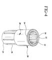
- Figs. 2-4 shows perspective views of pen needle hub 40, extender 30, and shield 20, respectively, in more detail.
- Outer cover 10 includes a closed distal end 11 and an open proximal end 12 that removably mounts to pen needle hub 40 to cover cannula 50, shield 20 and extender 30 for shipping prior to use.
- Pen needle hub 40 includes an open proximal end 41 formed by a skirt 54 having dimensions and means for attaching pen needle hub 40 on the distal end of a conventional medication delivery pen like the one described above.
- pen needle hub 40 includes a distal surface 45 having a centrally-located shaft 53 and a retention ring 43 extending therefrom. The inner surface of retention ring 43 is designed to mate with a flange 25 on proximal end 22 of shield 20, discussed further below.
- Retention ring 43 is shown in two sections that are separated at each end by a pair of openings 56 that are used to identify a long length injection setting and a short length injection setting, discussed further below.
- the long length injection setting and short length injection setting are also respectively identified by indicia 55, i.e., "L” and "S".
- shaft 53 includes a pair of ribs 49 set 180 degrees apart on the outer surface of shaft 53 and a pair of helical shaped grooves 44 extending from distal surface 45 to the distal end 42 of shaft 53. Grooves 44 from a helix profile of rib 49 to prevent extender 30 assembled on shaft 53 from disengaging from shaft 53 during the adjustment of the injection length by the user, as described below. Each groove 44 includes a slot 46 near distal end 42 of shaft 53 adjacent to one of the ribs 49 on the outer surface of shaft 53. Shaft 53 also includes a bore 47 through distal end 42 that receives double-ended cannula 50. Double-ended cannula 50 is epoxied or other wise permanently mounted therein so that distal point 51 extends from distal end 42 and a proximal point (not shown) extends into and is surrounded by skirt 54.
- Extender 30 is generally cylindrical in shape with an open distal end 31 and an open proximal end 32.
- a pair of protrusions 34 are formed on an inner surface 36 of extender 30 and a plurality of splines 33 are formed on an outer surface 37 of extender 30.
- Each protrusion 34 extends from distal end 31 towards proximal end 32 and includes a boss 35 at its proximal end.
- boss 35 are aligned with grooves 44 on shaft 53 and ride in grooves 44 to the top of each groove 44.
- Each boss 35 then snaps into slot 46 at the end of groove 44 to prevent extender 30 from moving forward and disengaging off shaft 53 during the adjustment of the injection length and removal of shield 20, discussed further below.
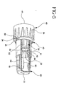
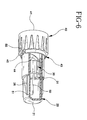
- extender 30 is rotatably mounted on shaft 53 such that each boss 35 travels within one of said grooves 44 from a retracted position, shown in Fig. 5, where a long injection length is set, to an extended position, shown in Fig. 6, where a short injection length is set.
- each boss 35 When extender 30 is in the retracted position, shown in Fig. 5, each boss 35 is located at a proximal end 48 of groove 44 such that open distal end 31 is flush with distal end 42 of shaft 53. When extender 30 is in the retracted position, the full length of cannula 50 from where cannula 50 is attached to distal end 42 of shaft 53 to distal point 51 is available for the injection. However, when extender 30 is in the extended position, shown in Fig. 6, each boss 35 is received and held in slot 46 at the distal end of each groove 44 such that open distal end 31 of extender 30 extends beyond distal end 42 of shaft 53.
- cannula 50 When extender 30 is in the extended position, the usable length of cannula 50 is reduced to the length extending from distal end 31 of extender 30 to distal point 51 of cannula 50.
- multiple slots 46 could be positioned along each groove 44 to provide for two or more predefined injection lengths, for example, a pen needle having a long length of 12.7mm, an intermediate length of 8mm and a short length of 5mm. Such an embodiment is also intended to be within the scope of the present invention.
- shield 20 The last major component of pen needle assembly 1 is shield 20. Shields are normally only used to protect the user from accidental needle sticks, however, shield 20 according to the present invention is designed for a second purpose. In the present invention, shield 20 is used to transfer radial torque to extender 30 and rotate extender 30 from and to different predefined- injection lengths. Shield 20 includes a closed distal end 21 and an open proximal end 22 and is divided into two sections: a smaller diameter distal section 26 closed by distal end 21 and a larger diameter proximal section 28 connected to distal section 26 by a shelf 27.
- Open proximal end 22 leads to proximal section 28 and is surrounded by a flange 25 having a notch 24 that is selectively aligned with one of the openings 56 to identify whether extender 30 is in the extended position (designated by "S") or in the retracted position (designated by “L”).
- Flange 25 is also used to attach shield 20 to needle hub 40 by mating with the inside surface of retention ring 43 discussed above. When flange 25 on shield 20 bottoms out on distal surface 45 of needle hub 40, flange 25 snaps into retention ring 43 to hold shield 20 in place during the process of setting the injection length and is removed prior to injection.
- Proximal section 28 also includes a plurality of splines 23 on an inner surface 29 that mate with splines 33 on extender 30 to cause extender 30 to rotate on shaft 53 and move extender 30 from its retracted position to its extended position or from its extended position back to its retracted position.
- pen needle assembly 1 of the present invention To use pen needle assembly 1 of the present invention, the user would first remove a sterility barrier (not shown) from pen needle assembly 1 and use outer cover 10 as a tool to transfer radial torque to pen needle hub 40 to assemble pen needle assembly 1 onto a conventional medication delivery pen. After which outer cover 10 is removed from pen needle hub 40. The user then chooses the length of the needle they require for their injection, for example, long or short. In the present embodiment, injection length of pen needle assembly 1 is preset to the long injection length ("L"), shown in Fig. 5. Therefore, if the user wants a long length injection, there would be no need to change the length. It would only be necessary to remove shield 20 and perform the injection.
- L long injection length
- the injection lengths could have the following combinations: Long Injection Length (mm) Short Injection Length (mm) 12.7 8 8 5 12.7 5
Abstract
Description
| Long Injection Length (mm) | Short Injection Length (mm) |
| 12.7 | 8 |
| 8 | 5 |
| 12.7 | 5 |
Claims (10)
- A pen needle assembly comprising:a hub having a double-ended cannula having a distal point;an extender movably mounted on said hub between a plurality of positions, wherein at each position said extender covers a predetermined portion of said cannula; andmeans for moving said extender on said hub between said plurality of positions.
- A pen needle assembly according to Claim 1, wherein:said hub includes an outer surface having a groove; andsaid extender includes an inner surface having a protrusion that travels in said groove as said extender moves between said plurality of positions.
- A pen needle assembly according to Claim 2, wherein said groove includes a slot for receiving said protrusion on said extender when said extender is at one of said plurality of positions.
- A pen needle assembly according to Claim 2, wherein:said protrusion on said extender includes a boss extending from said protrusion into said extender; andsaid groove includes a slot for receiving said boss when said extender is at one of said plurality of positions.
- A pen needle assembly according to Claim 2, wherein said groove has a helical shape that causes said extender to rotate around said hub as said extender moves between said plurality of positions.
- A pen needle assembly according to Claim 5, wherein said extender further includes a spline on an outer surface that is used by said moving means to rotate said extender and move said extender between said plurality of positions.
- A pen needle assembly according to Claim 6, wherein said means for moving said extender on said hub includes a shield having an internal spline that mates with said spline on said extender to rotate said extender and move said extender between said plurality of positions.
- A pen needle assembly according to Claim 7, wherein said hub further includes a retaining ring for rotatably mounting said shield on said hub to shield said distal point of said cannula and permit said shield to be rotated on said hub and rotate said extender between said plurality of positions.
- A pen needle assembly according to Claim 8, further comprising an outer cover that receives said hub to cover said cannula, said extender and said shield prior to using said pen needle assembly.
- A pen needle assembly according to Claim 1, wherein said means for moving said extender on said hub includes a shield that mates with said extender to move said extender between said plurality of positions.
Applications Claiming Priority (2)
| Application Number | Priority Date | Filing Date | Title |
|---|---|---|---|
| US08/938,271 US5944700A (en) | 1997-09-26 | 1997-09-26 | Adjustable injection length pen needle |
| US938271 | 1997-09-26 |
Publications (3)
| Publication Number | Publication Date |
|---|---|
| EP0904790A2 true EP0904790A2 (en) | 1999-03-31 |
| EP0904790A3 EP0904790A3 (en) | 1999-08-04 |
| EP0904790B1 EP0904790B1 (en) | 2003-03-12 |
Family
ID=25471193
Family Applications (1)
| Application Number | Title | Priority Date | Filing Date |
|---|---|---|---|
| EP98307469A Expired - Lifetime EP0904790B1 (en) | 1997-09-26 | 1998-09-15 | Adjustabel injection length pen needle |
Country Status (6)
| Country | Link |
|---|---|
| US (1) | US5944700A (en) |
| EP (1) | EP0904790B1 (en) |
| JP (1) | JP4249297B2 (en) |
| CA (1) | CA2245227C (en) |
| DE (1) | DE69812019T2 (en) |
| ES (1) | ES2195281T3 (en) |
Cited By (16)
| Publication number | Priority date | Publication date | Assignee | Title |
|---|---|---|---|---|
| EP1092444A1 (en) * | 1999-10-14 | 2001-04-18 | Becton Dickinson and Company | Intradermal delivery device including a needle assembly |
| EP1142534A1 (en) * | 2000-04-06 | 2001-10-10 | Pz Htl S.A. | Blood sampling device with adjustable puncture depth |
| US6569143B2 (en) | 1999-10-14 | 2003-05-27 | Becton, Dickinson And Company | Method of intradermally injecting substances |
| US6569123B2 (en) | 1999-10-14 | 2003-05-27 | Becton, Dickinson And Company | Prefillable intradermal injector |
| US6689118B2 (en) | 1999-10-14 | 2004-02-10 | Becton Dickinson And Company | Method of intradermally injecting substances |
| EP1393693A1 (en) * | 2002-08-28 | 2004-03-03 | ELM-Plastic GmbH | Drug dispensing instrument |
| US6843781B2 (en) | 1999-10-14 | 2005-01-18 | Becton, Dickinson And Company | Intradermal needle |
| US7083599B2 (en) | 1999-10-14 | 2006-08-01 | Becton, Dickinson And Company | Prefillable intradermal delivery device |
| US7241275B2 (en) | 1999-10-14 | 2007-07-10 | Becton, Dickinson And Company | Intradermal needle |
| EP2477676A1 (en) * | 2009-09-15 | 2012-07-25 | Becton, Dickinson and Company | Self-injection device |
| US8267890B2 (en) | 2003-01-30 | 2012-09-18 | Becton, Dickinson And Company | Intradermal delivery device with contoured skin engaging surface geometry |
| US8557251B2 (en) | 2001-02-23 | 2013-10-15 | Glaxosmithkline Biologicals, Sa | Non-live trivalent influenza vaccine for one-dose intradermal delivery |
| US9440031B2 (en) | 2008-12-23 | 2016-09-13 | Sanofi-Aventis Deutschland Gmbh | Drug delivery device |
| WO2016180924A1 (en) * | 2015-05-13 | 2016-11-17 | Hahn-Schickard-Gesellschaft für angewandte Forschung e.V. | Attachment for or on a device for injecting a fluid into or under the skin |
| EP3407941A4 (en) * | 2015-01-30 | 2019-12-04 | Becton, Dickinson And Company | Pen needle assembly |
| WO2023191770A1 (en) * | 2022-03-29 | 2023-10-05 | Embecta Corp. | Pen needle assembly and retractable needle shield |
Families Citing this family (99)
| Publication number | Priority date | Publication date | Assignee | Title |
|---|---|---|---|---|
| IL114960A0 (en) | 1995-03-20 | 1995-12-08 | Medimop Medical Projects Ltd | Flow control device |
| BR9612260A (en) * | 1995-12-22 | 1999-07-13 | Novo Nordisk As | Injection needle |
| US6482176B1 (en) * | 1997-11-27 | 2002-11-19 | Disetronic Licensing Ag | Method and device for controlling the introduction depth of an injection needle |
| US6560975B1 (en) | 1999-11-22 | 2003-05-13 | Leonard Weldon | Method and means for pain-free dental injections |
| JP2003523804A (en) * | 2000-01-27 | 2003-08-12 | アフラ デザイン ピーティーワイ.リミティッド | Single use syringe |
| US6547764B2 (en) * | 2000-05-31 | 2003-04-15 | Novo Nordisk A/S | Double pointed injection needle |
| JP5058425B2 (en) | 2000-08-02 | 2012-10-24 | ベクトン・ディキンソン・アンド・カンパニー | Pen needle and safety shield system |
| US6986760B2 (en) * | 2000-08-02 | 2006-01-17 | Becton, Dickinson And Company | Pen needle and safety shield system |
| US6387078B1 (en) * | 2000-12-21 | 2002-05-14 | Gillespie, Iii Richard D. | Automatic mixing and injecting apparatus |
| US20060018877A1 (en) * | 2001-06-29 | 2006-01-26 | Mikszta John A | Intradermal delivery of vacccines and therapeutic agents |
| BR0210628A (en) * | 2001-06-29 | 2004-08-10 | Becton Dickinson Co | Intradermal release of vaccines and genetic therapeutic agents via microcannula |
| EP1557191B2 (en) * | 2001-11-30 | 2016-09-07 | Novo Nordisk A/S | A safety needle assembly |
| US8932264B2 (en) * | 2003-08-11 | 2015-01-13 | Becton, Dickinson And Company | Medication delivery pen assembly with needle locking safety shield |
| DE20317377U1 (en) * | 2003-11-03 | 2005-03-17 | B D Medico S A R L | injection device |
| US20050159768A1 (en) * | 2004-01-15 | 2005-07-21 | Home Diagnostics, Inc. | Lancing device |
| IL161660A0 (en) | 2004-04-29 | 2004-09-27 | Medimop Medical Projects Ltd | Liquid drug delivery device |
| US7556149B2 (en) * | 2004-06-07 | 2009-07-07 | Ultimed, Inc. | Sharps container for safe transportation and dispensing of unused pen needle assemblies and for safe storage of used pen needle assemblies |
| US7665605B2 (en) * | 2004-08-14 | 2010-02-23 | Ultimed, Inc. | Sharps container for (I) safe disposal and storage of a single used medical pen needle and/or (II) safe storage and dispensing of a single unused medical pen needle |
| AU2005313993A1 (en) * | 2004-12-09 | 2006-06-15 | West Pharmaceutical Services, Inc. | Breech loaded fixed needle syringe and automatic injection device having the same |
| CN1824339B (en) * | 2005-02-21 | 2011-05-11 | 住友电木株式会社 | Medical implement |
| WO2007011888A2 (en) * | 2005-07-18 | 2007-01-25 | Pharma-Pen Holdings, Inc. | Auto-injection syringe having vent device |
| DK1919432T3 (en) | 2005-08-11 | 2012-01-30 | Medimop Medical Projects Ltd | Liquid Medication Transfer Devices for Safe Safe Resting Connection on Medical Vials |
| WO2007047403A1 (en) * | 2005-10-13 | 2007-04-26 | Becton, Dickinson And Company | Disposable needle and hub assembly |
| US7988675B2 (en) * | 2005-12-08 | 2011-08-02 | West Pharmaceutical Services Of Delaware, Inc. | Automatic injection and retraction devices for use with pre-filled syringe cartridges |
| JP4195900B2 (en) * | 2005-12-14 | 2008-12-17 | 株式会社スズケン | Needle cartridge and syringe |
| US7914547B2 (en) * | 2006-06-15 | 2011-03-29 | Abbott Diabetes Care Inc. | Adjustable lancing devices and methods |
| IL182605A0 (en) | 2007-04-17 | 2007-07-24 | Medimop Medical Projects Ltd | Fluid control device with manually depressed actuator |
| CN101918074B (en) | 2007-09-18 | 2013-02-27 | 麦迪麦珀医疗工程有限公司 | Medicament mixing and injection apparatus |
| IL186290A0 (en) | 2007-09-25 | 2008-01-20 | Medimop Medical Projects Ltd | Liquid drug delivery devices for use with syringe having widened distal tip |
| EP3153198A1 (en) * | 2008-01-15 | 2017-04-12 | Becton, Dickinson and Company | Medical injector with pen needle assembly |
| US8029526B2 (en) * | 2008-08-14 | 2011-10-04 | Abbott Diabetes Care Inc. | Cocking mechanism for lancing device |
| WO2010077278A1 (en) | 2008-12-09 | 2010-07-08 | Becton, Dickinson And Company | Dual-chambered drug delivery device for high pressure injections |
| WO2010077280A1 (en) | 2008-12-09 | 2010-07-08 | Becton, Dickinson And Company | Open and closed valve medication delivery system for high pressure injections |
| JP5600115B2 (en) | 2008-12-09 | 2014-10-01 | ベクトン・ディキンソン・アンド・カンパニー | Drug delivery system to increase lever and gear force for high pressure injection system |
| JP5739346B2 (en) | 2008-12-09 | 2015-06-24 | ベクトン・ディキンソン・アンド・カンパニーBecton, Dickinson And Company | Multi-stroke delivery pumping mechanism for high-pressure injectable drug delivery devices |
| EP2201976A1 (en) * | 2008-12-23 | 2010-06-30 | Sanofi-Aventis Deutschland GmbH | Apparatus for holding a cover of a needle unit and method |
| KR101106495B1 (en) * | 2009-01-14 | 2012-01-20 | 방시열 | Lancing depth adjustable pipe assembly for injector |
| WO2010090734A1 (en) * | 2009-02-06 | 2010-08-12 | Becton, Dickinson And Company | Pen needle assembly having biodegradable components |
| EP3488885B1 (en) * | 2009-03-03 | 2021-04-28 | Becton, Dickinson and Company | Combination of needle hub and shell for use with pen injector |
| USD641080S1 (en) | 2009-03-31 | 2011-07-05 | Medimop Medical Projects Ltd. | Medical device having syringe port with locking mechanism |
| US8500688B2 (en) * | 2009-04-16 | 2013-08-06 | Medtronic, Inc. | Retrograde coronary sinus perfusion cannula and methods of using same |
| CA3016519C (en) * | 2009-09-18 | 2020-05-26 | Becton, Dickinson And Company | Separable hub post of pen needle |
| IL201323A0 (en) | 2009-10-01 | 2010-05-31 | Medimop Medical Projects Ltd | Fluid transfer device for assembling a vial with pre-attached female connector |
| IL202069A0 (en) | 2009-11-12 | 2010-06-16 | Medimop Medical Projects Ltd | Fluid transfer device with sealing arrangement |
| IL202070A0 (en) | 2009-11-12 | 2010-06-16 | Medimop Medical Projects Ltd | Inline liquid drug medical device |
| CN102711712B (en) | 2010-02-24 | 2014-08-13 | 麦迪麦珀医疗工程有限公司 | Fluid transfer assembly with venting arrangement |
| JP5709905B2 (en) | 2010-02-24 | 2015-04-30 | メディモップ・メディカル・プロジェクツ・リミテッド | Liquid transfer device including vial adapter with vent |
| WO2012023938A1 (en) | 2010-08-19 | 2012-02-23 | West Pharmaceutical Services, Inc. | Rigid needle shield |
| US9993599B2 (en) * | 2010-08-23 | 2018-06-12 | Becton, Dickinson And Company | Skin engagement member for use with needle assembly or medical injector |
| USD669980S1 (en) | 2010-10-15 | 2012-10-30 | Medimop Medical Projects Ltd. | Vented vial adapter |
| IL209290A0 (en) | 2010-11-14 | 2011-01-31 | Medimop Medical Projects Ltd | Inline liquid drug medical device having rotary flow control member |
| IL212420A0 (en) | 2011-04-17 | 2011-06-30 | Medimop Medical Projects Ltd | Liquid drug transfer assembly |
| EP2517746A1 (en) * | 2011-04-29 | 2012-10-31 | Sanofi-Aventis Deutschland GmbH | Needle assembly storage system |
| IL215699A0 (en) | 2011-10-11 | 2011-12-29 | Medimop Medical Projects Ltd | Liquid drug reconstitution assemblage for use with iv bag and drug vial |
| US8506476B1 (en) | 2011-10-25 | 2013-08-13 | James Wright O'Mara, Jr. | Injection device for endoscopy |
| USD674088S1 (en) | 2012-02-13 | 2013-01-08 | Medimop Medical Projects Ltd. | Vial adapter |
| USD737436S1 (en) | 2012-02-13 | 2015-08-25 | Medimop Medical Projects Ltd. | Liquid drug reconstitution assembly |
| USD720451S1 (en) | 2012-02-13 | 2014-12-30 | Medimop Medical Projects Ltd. | Liquid drug transfer assembly |
| WO2013122941A1 (en) * | 2012-02-13 | 2013-08-22 | Becton, Dickinson And Company | Medical cannula package |
| IL219065A0 (en) | 2012-04-05 | 2012-07-31 | Medimop Medical Projects Ltd | Fluid transfer device with manual operated cartridge release arrangement |
| IL221635A0 (en) | 2012-08-26 | 2012-12-31 | Medimop Medical Projects Ltd | Drug vial mixing and transfer device for use with iv bag and drug vial |
| IL221634A0 (en) | 2012-08-26 | 2012-12-31 | Medimop Medical Projects Ltd | Universal drug vial adapter |
| BR112015005157B1 (en) | 2012-09-13 | 2020-12-08 | Medimop Medical Projects Ltd | telescopic female drug bottle adapter |
| USD734868S1 (en) | 2012-11-27 | 2015-07-21 | Medimop Medical Projects Ltd. | Drug vial adapter with downwardly depending stopper |
| IL225734A0 (en) | 2013-04-14 | 2013-09-30 | Medimop Medical Projects Ltd | Ready-to-use drug vial assemblages including drug vial and drug vial closure having fluid transfer member, and drug vial closure therefor |
| DK2983745T3 (en) | 2013-05-10 | 2018-10-22 | West Pharma Services Il Ltd | Medical devices comprising ampoule adapter with interconnected module for dry drug |
| USD765837S1 (en) | 2013-08-07 | 2016-09-06 | Medimop Medical Projects Ltd. | Liquid transfer device with integral vial adapter |
| US10688295B2 (en) | 2013-08-07 | 2020-06-23 | West Pharma. Services IL, Ltd. | Liquid transfer devices for use with infusion liquid containers |
| USD767124S1 (en) | 2013-08-07 | 2016-09-20 | Medimop Medical Projects Ltd. | Liquid transfer device with integral vial adapter |
| PL234202B1 (en) | 2013-09-30 | 2020-01-31 | Htl Strefa Spolka Akcyjna | Safety needle device |
| US10004845B2 (en) | 2014-04-18 | 2018-06-26 | Becton, Dickinson And Company | Split piston metering pump |
| WO2015165717A1 (en) * | 2014-04-29 | 2015-11-05 | Carebay Europe Ltd | Device for adjusting needle insertion depth |
| KR101462372B1 (en) * | 2014-05-28 | 2014-11-20 | 이승욱 | One touch type pen needle |
| USD768851S1 (en) | 2014-06-30 | 2016-10-11 | Htl-Strefa Spolka Akcyjna | Safety needle device |
| USD768852S1 (en) | 2014-06-30 | 2016-10-11 | Htl-Strefa Spolka Akcyjna | Safety needle device |
| US9416775B2 (en) | 2014-07-02 | 2016-08-16 | Becton, Dickinson And Company | Internal cam metering pump |
| USD757933S1 (en) | 2014-09-11 | 2016-05-31 | Medimop Medical Projects Ltd. | Dual vial adapter assemblage |
| CN104528082B (en) * | 2014-12-24 | 2016-11-30 | 苏州捷碧医疗科技有限公司 | The pen-type injector syringe needle of a kind of simple packaging and using method thereof |
| US10285907B2 (en) | 2015-01-05 | 2019-05-14 | West Pharma. Services IL, Ltd. | Dual vial adapter assemblages with quick release drug vial adapter for ensuring correct usage |
| US10357429B2 (en) | 2015-07-16 | 2019-07-23 | West Pharma. Services IL, Ltd. | Liquid drug transfer devices for secure telescopic snap fit on injection vials |
| DE102015111835A1 (en) * | 2015-07-21 | 2017-01-26 | Gerresheimer Regensburg Gmbh | Safety device for a syringe |
| USD801522S1 (en) | 2015-11-09 | 2017-10-31 | Medimop Medical Projects Ltd. | Fluid transfer assembly |
| US10940086B2 (en) * | 2015-11-12 | 2021-03-09 | Scalpal Llc | Bottle support and protective collar |
| WO2017090042A1 (en) | 2015-11-25 | 2017-06-01 | Medimop Medical Projects Ltd | Dual vial adapter assemblage including drug vial adapter with self-sealing access valve |
| IL245803A0 (en) | 2016-05-24 | 2016-08-31 | West Pharma Services Il Ltd | Dual vial adapter assemblages including vented drug vial adapter and vented liquid vial adapter |
| IL245800A0 (en) | 2016-05-24 | 2016-08-31 | West Pharma Services Il Ltd | Dual vial adapter assemblages including identical twin vial adapters |
| IL246073A0 (en) | 2016-06-06 | 2016-08-31 | West Pharma Services Il Ltd | Fluid transfer devices for use with drug pump cartridge having slidable driving plunger |
| IL247376A0 (en) | 2016-08-21 | 2016-12-29 | Medimop Medical Projects Ltd | Syringe assembly |
| USD832430S1 (en) | 2016-11-15 | 2018-10-30 | West Pharma. Services IL, Ltd. | Dual vial adapter assemblage |
| IL249408A0 (en) | 2016-12-06 | 2017-03-30 | Medimop Medical Projects Ltd | Liquid transfer device for use with infusion liquid container and pincers-like hand tool for use therewith for releasing intact drug vial therefrom |
| IL251458A0 (en) | 2017-03-29 | 2017-06-29 | Medimop Medical Projects Ltd | User actuated liquid drug transfer devices for use in ready-to-use (rtu) liquid drug transfer assemblages |
| IL254802A0 (en) | 2017-09-29 | 2017-12-31 | Medimop Medical Projects Ltd | Dual vial adapter assemblages with twin vented female vial adapters |
| JP1630477S (en) | 2018-07-06 | 2019-05-07 | ||
| USD923812S1 (en) | 2019-01-16 | 2021-06-29 | West Pharma. Services IL, Ltd. | Medication mixing apparatus |
| JP1648075S (en) | 2019-01-17 | 2019-12-16 | ||
| EP3917486B1 (en) | 2019-01-31 | 2023-03-08 | West Pharma. Services IL, Ltd | Liquid transfer device |
| CN109718429B (en) * | 2019-02-15 | 2024-01-16 | 贝普医疗科技股份有限公司 | Safety insulin needle |
| US11484470B2 (en) | 2019-04-30 | 2022-11-01 | West Pharma. Services IL, Ltd. | Liquid transfer device with dual lumen IV spike |
| USD956958S1 (en) | 2020-07-13 | 2022-07-05 | West Pharma. Services IL, Ltd. | Liquid transfer device |
Citations (4)
| Publication number | Priority date | Publication date | Assignee | Title |
|---|---|---|---|---|
| US3605744A (en) * | 1969-04-22 | 1971-09-20 | Edward M Dwyer | Injection apparatus and method of injecting |
| US4693708A (en) * | 1986-10-16 | 1987-09-15 | Wanderer Alan A | Combination needle shield/needle guard device for a hypodermic syringe with a permanently attached needle |
| US4747837A (en) * | 1987-05-01 | 1988-05-31 | Hauck Martin W | Syringe needle recapping protective device |
| US4801295A (en) * | 1986-05-22 | 1989-01-31 | Spencer Treesa A | Disposable hypodermic syringe and needle combination having retractable, accident preventing sheath |
Family Cites Families (3)
| Publication number | Priority date | Publication date | Assignee | Title |
|---|---|---|---|---|
| US4897083A (en) * | 1988-05-09 | 1990-01-30 | Martell Michael D | Syringe needle guard |
| US5190521A (en) * | 1990-08-22 | 1993-03-02 | Tecnol Medical Products, Inc. | Apparatus and method for raising a skin wheal and anesthetizing skin |
| US5336199A (en) * | 1993-11-12 | 1994-08-09 | Castillo Leo S | Medical needle and needle sheath assembly |
-
1997
- 1997-09-26 US US08/938,271 patent/US5944700A/en not_active Expired - Lifetime
-
1998
- 1998-08-14 CA CA002245227A patent/CA2245227C/en not_active Expired - Lifetime
- 1998-09-15 ES ES98307469T patent/ES2195281T3/en not_active Expired - Lifetime
- 1998-09-15 EP EP98307469A patent/EP0904790B1/en not_active Expired - Lifetime
- 1998-09-15 DE DE69812019T patent/DE69812019T2/en not_active Expired - Lifetime
- 1998-09-28 JP JP27397798A patent/JP4249297B2/en not_active Expired - Lifetime
Patent Citations (4)
| Publication number | Priority date | Publication date | Assignee | Title |
|---|---|---|---|---|
| US3605744A (en) * | 1969-04-22 | 1971-09-20 | Edward M Dwyer | Injection apparatus and method of injecting |
| US4801295A (en) * | 1986-05-22 | 1989-01-31 | Spencer Treesa A | Disposable hypodermic syringe and needle combination having retractable, accident preventing sheath |
| US4693708A (en) * | 1986-10-16 | 1987-09-15 | Wanderer Alan A | Combination needle shield/needle guard device for a hypodermic syringe with a permanently attached needle |
| US4747837A (en) * | 1987-05-01 | 1988-05-31 | Hauck Martin W | Syringe needle recapping protective device |
Cited By (20)
| Publication number | Priority date | Publication date | Assignee | Title |
|---|---|---|---|---|
| US7241275B2 (en) | 1999-10-14 | 2007-07-10 | Becton, Dickinson And Company | Intradermal needle |
| US6494865B1 (en) | 1999-10-14 | 2002-12-17 | Becton Dickinson And Company | Intradermal delivery device including a needle assembly |
| US6569143B2 (en) | 1999-10-14 | 2003-05-27 | Becton, Dickinson And Company | Method of intradermally injecting substances |
| US6569123B2 (en) | 1999-10-14 | 2003-05-27 | Becton, Dickinson And Company | Prefillable intradermal injector |
| US6689118B2 (en) | 1999-10-14 | 2004-02-10 | Becton Dickinson And Company | Method of intradermally injecting substances |
| US6843781B2 (en) | 1999-10-14 | 2005-01-18 | Becton, Dickinson And Company | Intradermal needle |
| US7083599B2 (en) | 1999-10-14 | 2006-08-01 | Becton, Dickinson And Company | Prefillable intradermal delivery device |
| EP1092444A1 (en) * | 1999-10-14 | 2001-04-18 | Becton Dickinson and Company | Intradermal delivery device including a needle assembly |
| US9750897B2 (en) | 1999-10-14 | 2017-09-05 | Becton, Dickinson And Company | Intradermal delivery device including a needle assembly |
| EP1142534A1 (en) * | 2000-04-06 | 2001-10-10 | Pz Htl S.A. | Blood sampling device with adjustable puncture depth |
| US8557251B2 (en) | 2001-02-23 | 2013-10-15 | Glaxosmithkline Biologicals, Sa | Non-live trivalent influenza vaccine for one-dose intradermal delivery |
| EP1393693A1 (en) * | 2002-08-28 | 2004-03-03 | ELM-Plastic GmbH | Drug dispensing instrument |
| US8267890B2 (en) | 2003-01-30 | 2012-09-18 | Becton, Dickinson And Company | Intradermal delivery device with contoured skin engaging surface geometry |
| US9440031B2 (en) | 2008-12-23 | 2016-09-13 | Sanofi-Aventis Deutschland Gmbh | Drug delivery device |
| US9408984B2 (en) | 2009-09-15 | 2016-08-09 | Becton, Dickinson And Company | Self-injection device |
| EP2477676A4 (en) * | 2009-09-15 | 2014-08-27 | Becton Dickinson Co | Self-injection device |
| EP2477676A1 (en) * | 2009-09-15 | 2012-07-25 | Becton, Dickinson and Company | Self-injection device |
| EP3407941A4 (en) * | 2015-01-30 | 2019-12-04 | Becton, Dickinson And Company | Pen needle assembly |
| WO2016180924A1 (en) * | 2015-05-13 | 2016-11-17 | Hahn-Schickard-Gesellschaft für angewandte Forschung e.V. | Attachment for or on a device for injecting a fluid into or under the skin |
| WO2023191770A1 (en) * | 2022-03-29 | 2023-10-05 | Embecta Corp. | Pen needle assembly and retractable needle shield |
Also Published As
| Publication number | Publication date |
|---|---|
| JP4249297B2 (en) | 2009-04-02 |
| JPH11169461A (en) | 1999-06-29 |
| EP0904790B1 (en) | 2003-03-12 |
| US5944700A (en) | 1999-08-31 |
| ES2195281T3 (en) | 2003-12-01 |
| EP0904790A3 (en) | 1999-08-04 |
| CA2245227C (en) | 2002-11-12 |
| CA2245227A1 (en) | 1999-03-26 |
| DE69812019D1 (en) | 2003-04-17 |
| DE69812019T2 (en) | 2003-11-27 |
Similar Documents
| Publication | Publication Date | Title |
|---|---|---|
| US5944700A (en) | Adjustable injection length pen needle | |
| US5688251A (en) | Cartridge loading and priming mechanism for a pen injector | |
| US7169132B2 (en) | Medication delivery pen | |
| US5725508A (en) | Quick connect medication delivery pen | |
| EP0861101B1 (en) | Medication delivery pen with cap actuated dose delivery clutch | |
| US5827232A (en) | Quick connect medication delivery pen | |
| EP0702970B1 (en) | Medication delivery pen with variable increment dose scale | |
| US5941857A (en) | Disposable pen needle | |
| US6090082A (en) | Vial retainer interface to a medication delivery pen | |
| US5931817A (en) | Pen needle assembly | |
| EP0897728B1 (en) | Medication delivery pen | |
| EP0937472B1 (en) | Repeat-dose medication delivery pen | |
| CA2261479C (en) | Threaded medication cartridge | |
| US5569214A (en) | Dose setting knob adapter for medication delivery pen |
Legal Events
| Date | Code | Title | Description |
|---|---|---|---|
| PUAI | Public reference made under article 153(3) epc to a published international application that has entered the european phase |
Free format text: ORIGINAL CODE: 0009012 |
|
| AK | Designated contracting states |
Kind code of ref document: A2 Designated state(s): DE ES FR GB IT |
|
| AX | Request for extension of the european patent |
Free format text: AL;LT;LV;MK;RO;SI |
|
| PUAL | Search report despatched |
Free format text: ORIGINAL CODE: 0009013 |
|
| AK | Designated contracting states |
Kind code of ref document: A3 Designated state(s): AT BE CH CY DE DK ES FI FR GB GR IE IT LI LU MC NL PT SE |
|
| AX | Request for extension of the european patent |
Free format text: AL;LT;LV;MK;RO;SI |
|
| RIC1 | Information provided on ipc code assigned before grant |
Free format text: 6A 61M 5/46 A, 6A 61M 5/32 B |
|
| 17P | Request for examination filed |
Effective date: 20000202 |
|
| AKX | Designation fees paid |
Free format text: AT BE CH CY DE LI |
|
| RBV | Designated contracting states (corrected) |
Designated state(s): DE ES FR GB IT |
|
| 17Q | First examination report despatched |
Effective date: 20010417 |
|
| GRAH | Despatch of communication of intention to grant a patent |
Free format text: ORIGINAL CODE: EPIDOS IGRA |
|
| GRAH | Despatch of communication of intention to grant a patent |
Free format text: ORIGINAL CODE: EPIDOS IGRA |
|
| GRAA | (expected) grant |
Free format text: ORIGINAL CODE: 0009210 |
|
| RIN1 | Information on inventor provided before grant (corrected) |
Inventor name: DIBIASI, MICHAEL A. Inventor name: NGUYEN, TUAN V. |
|
| AK | Designated contracting states |
Designated state(s): DE ES FR GB IT |
|
| REG | Reference to a national code |
Ref country code: GB Ref legal event code: FG4D |
|
| REF | Corresponds to: |
Ref document number: 69812019 Country of ref document: DE Date of ref document: 20030417 Kind code of ref document: P |
|
| ET | Fr: translation filed | ||
| PLBE | No opposition filed within time limit |
Free format text: ORIGINAL CODE: 0009261 |
|
| STAA | Information on the status of an ep patent application or granted ep patent |
Free format text: STATUS: NO OPPOSITION FILED WITHIN TIME LIMIT |
|
| 26N | No opposition filed |
Effective date: 20031215 |
|
| REG | Reference to a national code |
Ref country code: FR Ref legal event code: PLFP Year of fee payment: 19 |
|
| REG | Reference to a national code |
Ref country code: FR Ref legal event code: PLFP Year of fee payment: 20 |
|
| PGFP | Annual fee paid to national office [announced via postgrant information from national office to epo] |
Ref country code: IT Payment date: 20170828 Year of fee payment: 20 Ref country code: GB Payment date: 20170821 Year of fee payment: 20 Ref country code: DE Payment date: 20170821 Year of fee payment: 20 Ref country code: FR Payment date: 20170822 Year of fee payment: 20 |
|
| PGFP | Annual fee paid to national office [announced via postgrant information from national office to epo] |
Ref country code: ES Payment date: 20171003 Year of fee payment: 20 |
|
| REG | Reference to a national code |
Ref country code: DE Ref legal event code: R071 Ref document number: 69812019 Country of ref document: DE |
|
| REG | Reference to a national code |
Ref country code: GB Ref legal event code: PE20 Expiry date: 20180914 |
|
| PG25 | Lapsed in a contracting state [announced via postgrant information from national office to epo] |
Ref country code: GB Free format text: LAPSE BECAUSE OF EXPIRATION OF PROTECTION Effective date: 20180914 |
|
| REG | Reference to a national code |
Ref country code: ES Ref legal event code: FD2A Effective date: 20200904 |
|
| PG25 | Lapsed in a contracting state [announced via postgrant information from national office to epo] |
Ref country code: ES Free format text: LAPSE BECAUSE OF EXPIRATION OF PROTECTION Effective date: 20180916 |